WO2010055889A1 - 陰イオン交換膜及びその製造方法 - Google Patents
陰イオン交換膜及びその製造方法 Download PDFInfo
- Publication number
- WO2010055889A1 WO2010055889A1 PCT/JP2009/069290 JP2009069290W WO2010055889A1 WO 2010055889 A1 WO2010055889 A1 WO 2010055889A1 JP 2009069290 W JP2009069290 W JP 2009069290W WO 2010055889 A1 WO2010055889 A1 WO 2010055889A1
- Authority
- WO
- WIPO (PCT)
- Prior art keywords
- anion exchange
- raw material
- exchange membrane
- microporous film
- introduction
- Prior art date
- Legal status (The legal status is an assumption and is not a legal conclusion. Google has not performed a legal analysis and makes no representation as to the accuracy of the status listed.)
- Ceased
Links
Images

Classifications
-
- C—CHEMISTRY; METALLURGY
- C08—ORGANIC MACROMOLECULAR COMPOUNDS; THEIR PREPARATION OR CHEMICAL WORKING-UP; COMPOSITIONS BASED THEREON
- C08J—WORKING-UP; GENERAL PROCESSES OF COMPOUNDING; AFTER-TREATMENT NOT COVERED BY SUBCLASSES C08B, C08C, C08F, C08G or C08H
- C08J5/00—Manufacture of articles or shaped materials containing macromolecular substances
- C08J5/20—Manufacture of shaped structures of ion-exchange resins
- C08J5/22—Films, membranes or diaphragms
- C08J5/2206—Films, membranes or diaphragms based on organic and/or inorganic macromolecular compounds
- C08J5/2275—Heterogeneous membranes
-
- C—CHEMISTRY; METALLURGY
- C08—ORGANIC MACROMOLECULAR COMPOUNDS; THEIR PREPARATION OR CHEMICAL WORKING-UP; COMPOSITIONS BASED THEREON
- C08J—WORKING-UP; GENERAL PROCESSES OF COMPOUNDING; AFTER-TREATMENT NOT COVERED BY SUBCLASSES C08B, C08C, C08F, C08G or C08H
- C08J5/00—Manufacture of articles or shaped materials containing macromolecular substances
- C08J5/20—Manufacture of shaped structures of ion-exchange resins
- C08J5/22—Films, membranes or diaphragms
-
- B—PERFORMING OPERATIONS; TRANSPORTING
- B01—PHYSICAL OR CHEMICAL PROCESSES OR APPARATUS IN GENERAL
- B01J—CHEMICAL OR PHYSICAL PROCESSES, e.g. CATALYSIS OR COLLOID CHEMISTRY; THEIR RELEVANT APPARATUS
- B01J41/00—Anion exchange; Use of material as anion exchangers; Treatment of material for improving the anion exchange properties
- B01J41/08—Use of material as anion exchangers; Treatment of material for improving the anion exchange properties
- B01J41/12—Macromolecular compounds
- B01J41/14—Macromolecular compounds obtained by reactions only involving unsaturated carbon-to-carbon bonds
-
- C—CHEMISTRY; METALLURGY
- C08—ORGANIC MACROMOLECULAR COMPOUNDS; THEIR PREPARATION OR CHEMICAL WORKING-UP; COMPOSITIONS BASED THEREON
- C08F—MACROMOLECULAR COMPOUNDS OBTAINED BY REACTIONS ONLY INVOLVING CARBON-TO-CARBON UNSATURATED BONDS
- C08F226/00—Copolymers of compounds having one or more unsaturated aliphatic radicals, each having only one carbon-to-carbon double bond, and at least one being terminated by a single or double bond to nitrogen or by a heterocyclic ring containing nitrogen
- C08F226/02—Copolymers of compounds having one or more unsaturated aliphatic radicals, each having only one carbon-to-carbon double bond, and at least one being terminated by a single or double bond to nitrogen or by a heterocyclic ring containing nitrogen by a single or double bond to nitrogen
- C08F226/04—Diallylamine
-
- C—CHEMISTRY; METALLURGY
- C08—ORGANIC MACROMOLECULAR COMPOUNDS; THEIR PREPARATION OR CHEMICAL WORKING-UP; COMPOSITIONS BASED THEREON
- C08F—MACROMOLECULAR COMPOUNDS OBTAINED BY REACTIONS ONLY INVOLVING CARBON-TO-CARBON UNSATURATED BONDS
- C08F26/00—Homopolymers and copolymers of compounds having one or more unsaturated aliphatic radicals, each having only one carbon-to-carbon double bond, and at least one being terminated by a single or double bond to nitrogen or by a heterocyclic ring containing nitrogen
- C08F26/02—Homopolymers and copolymers of compounds having one or more unsaturated aliphatic radicals, each having only one carbon-to-carbon double bond, and at least one being terminated by a single or double bond to nitrogen or by a heterocyclic ring containing nitrogen by a single or double bond to nitrogen
-
- H—ELECTRICITY
- H01—ELECTRIC ELEMENTS
- H01B—CABLES; CONDUCTORS; INSULATORS; SELECTION OF MATERIALS FOR THEIR CONDUCTIVE, INSULATING OR DIELECTRIC PROPERTIES
- H01B1/00—Conductors or conductive bodies characterised by the conductive materials; Selection of materials as conductors
- H01B1/06—Conductors or conductive bodies characterised by the conductive materials; Selection of materials as conductors mainly consisting of other non-metallic substances
- H01B1/12—Conductors or conductive bodies characterised by the conductive materials; Selection of materials as conductors mainly consisting of other non-metallic substances organic substances
- H01B1/122—Ionic conductors
-
- H—ELECTRICITY
- H01—ELECTRIC ELEMENTS
- H01M—PROCESSES OR MEANS, e.g. BATTERIES, FOR THE DIRECT CONVERSION OF CHEMICAL ENERGY INTO ELECTRICAL ENERGY
- H01M8/00—Fuel cells; Manufacture thereof
- H01M8/02—Details
-
- H—ELECTRICITY
- H01—ELECTRIC ELEMENTS
- H01M—PROCESSES OR MEANS, e.g. BATTERIES, FOR THE DIRECT CONVERSION OF CHEMICAL ENERGY INTO ELECTRICAL ENERGY
- H01M8/00—Fuel cells; Manufacture thereof
- H01M8/10—Fuel cells with solid electrolytes
- H01M8/1016—Fuel cells with solid electrolytes characterised by the electrolyte material
- H01M8/1018—Polymeric electrolyte materials
- H01M8/102—Polymeric electrolyte materials characterised by the chemical structure of the main chain of the ion-conducting polymer
- H01M8/1023—Polymeric electrolyte materials characterised by the chemical structure of the main chain of the ion-conducting polymer having only carbon, e.g. polyarylenes, polystyrenes or polybutadiene-styrenes
-
- H—ELECTRICITY
- H01—ELECTRIC ELEMENTS
- H01M—PROCESSES OR MEANS, e.g. BATTERIES, FOR THE DIRECT CONVERSION OF CHEMICAL ENERGY INTO ELECTRICAL ENERGY
- H01M8/00—Fuel cells; Manufacture thereof
- H01M8/10—Fuel cells with solid electrolytes
- H01M8/1016—Fuel cells with solid electrolytes characterised by the electrolyte material
- H01M8/1018—Polymeric electrolyte materials
- H01M8/102—Polymeric electrolyte materials characterised by the chemical structure of the main chain of the ion-conducting polymer
- H01M8/103—Polymeric electrolyte materials characterised by the chemical structure of the main chain of the ion-conducting polymer having nitrogen, e.g. sulfonated polybenzimidazoles [S-PBI], polybenzimidazoles with phosphoric acid, sulfonated polyamides [S-PA] or sulfonated polyphosphazenes [S-PPh]
-
- H—ELECTRICITY
- H01—ELECTRIC ELEMENTS
- H01M—PROCESSES OR MEANS, e.g. BATTERIES, FOR THE DIRECT CONVERSION OF CHEMICAL ENERGY INTO ELECTRICAL ENERGY
- H01M8/00—Fuel cells; Manufacture thereof
- H01M8/10—Fuel cells with solid electrolytes
- H01M8/1016—Fuel cells with solid electrolytes characterised by the electrolyte material
- H01M8/1018—Polymeric electrolyte materials
- H01M8/1039—Polymeric electrolyte materials halogenated, e.g. sulfonated polyvinylidene fluorides
-
- H—ELECTRICITY
- H01—ELECTRIC ELEMENTS
- H01M—PROCESSES OR MEANS, e.g. BATTERIES, FOR THE DIRECT CONVERSION OF CHEMICAL ENERGY INTO ELECTRICAL ENERGY
- H01M8/00—Fuel cells; Manufacture thereof
- H01M8/10—Fuel cells with solid electrolytes
- H01M8/1016—Fuel cells with solid electrolytes characterised by the electrolyte material
- H01M8/1018—Polymeric electrolyte materials
- H01M8/1041—Polymer electrolyte composites, mixtures or blends
- H01M8/1044—Mixtures of polymers, of which at least one is ionically conductive
-
- H—ELECTRICITY
- H01—ELECTRIC ELEMENTS
- H01M—PROCESSES OR MEANS, e.g. BATTERIES, FOR THE DIRECT CONVERSION OF CHEMICAL ENERGY INTO ELECTRICAL ENERGY
- H01M8/00—Fuel cells; Manufacture thereof
- H01M8/10—Fuel cells with solid electrolytes
- H01M8/1016—Fuel cells with solid electrolytes characterised by the electrolyte material
- H01M8/1018—Polymeric electrolyte materials
- H01M8/1058—Polymeric electrolyte materials characterised by a porous support having no ion-conducting properties
-
- H—ELECTRICITY
- H01—ELECTRIC ELEMENTS
- H01M—PROCESSES OR MEANS, e.g. BATTERIES, FOR THE DIRECT CONVERSION OF CHEMICAL ENERGY INTO ELECTRICAL ENERGY
- H01M8/00—Fuel cells; Manufacture thereof
- H01M8/10—Fuel cells with solid electrolytes
- H01M8/1016—Fuel cells with solid electrolytes characterised by the electrolyte material
- H01M8/1018—Polymeric electrolyte materials
- H01M8/1069—Polymeric electrolyte materials characterised by the manufacturing processes
- H01M8/1072—Polymeric electrolyte materials characterised by the manufacturing processes by chemical reactions, e.g. in situ polymerisation or in situ crosslinking
-
- C—CHEMISTRY; METALLURGY
- C08—ORGANIC MACROMOLECULAR COMPOUNDS; THEIR PREPARATION OR CHEMICAL WORKING-UP; COMPOSITIONS BASED THEREON
- C08J—WORKING-UP; GENERAL PROCESSES OF COMPOUNDING; AFTER-TREATMENT NOT COVERED BY SUBCLASSES C08B, C08C, C08F, C08G or C08H
- C08J2379/00—Characterised by the use of macromolecular compounds obtained by reactions forming in the main chain of the macromolecule a linkage containing nitrogen with or without oxygen, or carbon only, not provided for in groups C08J2361/00 - C08J2377/00
- C08J2379/04—Polycondensates having nitrogen-containing heterocyclic rings in the main chain; Polyhydrazides; Polyamide acids or similar polyimide precursors
-
- Y—GENERAL TAGGING OF NEW TECHNOLOGICAL DEVELOPMENTS; GENERAL TAGGING OF CROSS-SECTIONAL TECHNOLOGIES SPANNING OVER SEVERAL SECTIONS OF THE IPC; TECHNICAL SUBJECTS COVERED BY FORMER USPC CROSS-REFERENCE ART COLLECTIONS [XRACs] AND DIGESTS
- Y02—TECHNOLOGIES OR APPLICATIONS FOR MITIGATION OR ADAPTATION AGAINST CLIMATE CHANGE
- Y02E—REDUCTION OF GREENHOUSE GAS [GHG] EMISSIONS, RELATED TO ENERGY GENERATION, TRANSMISSION OR DISTRIBUTION
- Y02E60/00—Enabling technologies; Technologies with a potential or indirect contribution to GHG emissions mitigation
- Y02E60/30—Hydrogen technology
- Y02E60/50—Fuel cells
-
- Y—GENERAL TAGGING OF NEW TECHNOLOGICAL DEVELOPMENTS; GENERAL TAGGING OF CROSS-SECTIONAL TECHNOLOGIES SPANNING OVER SEVERAL SECTIONS OF THE IPC; TECHNICAL SUBJECTS COVERED BY FORMER USPC CROSS-REFERENCE ART COLLECTIONS [XRACs] AND DIGESTS
- Y02—TECHNOLOGIES OR APPLICATIONS FOR MITIGATION OR ADAPTATION AGAINST CLIMATE CHANGE
- Y02P—CLIMATE CHANGE MITIGATION TECHNOLOGIES IN THE PRODUCTION OR PROCESSING OF GOODS
- Y02P70/00—Climate change mitigation technologies in the production process for final industrial or consumer products
- Y02P70/50—Manufacturing or production processes characterised by the final manufactured product
Definitions
- the present invention relates to an anion exchange membrane and a method for producing the same. More specifically, the present invention relates to an anion exchange membrane that can be suitably used as a fuel cell membrane and a method for producing the same.
- the solid polymer fuel cell is a fuel cell using a solid polymer such as an ion exchange resin as an electrolyte, and has a characteristic that the operating temperature is relatively low.
- the solid polymer fuel cell includes a solid polymer electrolyte membrane 6 in a space in the battery partition wall 1 having a fuel gas flow hole 2 and an oxidant gas flow hole 3 communicating with the outside.
- the fuel chamber 7 and the oxidant gas flow hole 3 are connected to the outside through the fuel gas flow hole 2 and partitioned by a joined body in which the fuel chamber side gas diffusion electrode 4 and the oxidant chamber side gas diffusion electrode 5 are joined to both surfaces of It has a basic structure in which an oxidant chamber 8 communicating with the outside is formed.
- a fuel made of hydrogen gas or methanol is supplied to the fuel chamber 7 through the fuel circulation hole 2 and the oxidant gas circulation hole 3 is supplied to the oxidant chamber 8.
- Electric energy is generated by supplying an oxygen-containing gas such as oxygen or air as an oxidant and connecting an external load circuit between the two gas diffusion electrodes.
- protons (hydrogen ions) generated by contact of the catalyst and fuel contained in the electrode in the fuel chamber side gas diffusion electrode 4 are solid. It conducts through the polymer electrolyte membrane 6 and moves to the oxidant chamber 8, and reacts with oxygen in the oxidant gas at the oxidant chamber side gas diffusion electrode 5 to generate water.
- the electrons generated simultaneously with the protons in the fuel chamber side gas diffusion electrode 4 move to the oxidant chamber side gas diffusion electrode 5 through the external load circuit, so that the energy of the reaction can be used as electric energy.
- a perfluorocarbon sulfonic acid resin membrane is most commonly used as the cation exchange type electrolyte membrane.
- the reaction field is strongly acidic, only a noble metal catalyst can be used, and the perfluorocarbon sulfonic acid resin membrane is also expensive, so there is a limit to cost reduction.
- the water retention capacity is not sufficient, it is necessary to supply water.
- the physical strength is low, it is difficult to reduce electrical resistance by thinning.
- Patent Documents 1 to 3 When an anion exchange membrane is used, since the ion species moving in the solid polymer electrolyte membrane 6 are hydroxide ions, the reaction field becomes basic, and a transition metal can be used as a catalyst. . Therefore, the above problem (i) can be solved.
- the material of the base material of the hydrocarbon-based anion exchange membrane is a hydrocarbon-based resin such as polyolefin that can be easily surface-modified and processed as compared with the perfluorocarbon resin, the above (ii) and (iii) This problem can also be improved.
- the generation mechanism of electric energy in a fuel cell using an anion exchange membrane is as follows, unlike the case of using a cation exchange membrane. That is, by supplying hydrogen or methanol to the fuel chamber side and oxygen and water to the oxidant chamber side, the catalyst contained in the electrode and the oxygen and water in the oxidant chamber side gas diffusion electrode 5 In contact, hydroxide ions are produced. The hydroxide ions are transferred to the fuel chamber 7 through the solid polymer electrolyte membrane 6 made of the hydrocarbon-based anion exchange membrane, and react with the fuel at the fuel chamber side gas diffusion electrode 4 to give water. Along with this, electrons generated by the fuel chamber side gas diffusion electrode 4 are moved to the oxidant chamber side gas diffusion electrode 5 through an external load circuit and used as electric energy.
- Examples of the anion exchange group used in the hydrocarbon-based anion exchange membrane having such advantages include its excellent ion conductivity and the availability of raw materials for producing the anion exchange membrane. Therefore, quaternary ammonium groups are generally used (Patent Documents 1 to 3 above).
- Such a hydrocarbon-based anion exchange membrane having a quaternary ammonium group as an anion exchange group (hereinafter also referred to as “quaternary ammonium-type hydrocarbon anion exchange membrane”) is usually made of chloromethylstyrene or the like.
- a polymerizable composition comprising a polymerizable monomer having a halogenoalkyl group and a crosslinkable polymerizable monomer is brought into contact with the microporous film, and the polymerizable composition is filled in the voids of the microporous film. And then cured and polymerized to a crosslinked hydrocarbon-based resin having a halogenoalkyl group, and then the halogenoalkyl group is converted to a quaternary ammonium group, and then the counter ion of the quaternary ammonium group is converted into a hydroxide ion.
- This method has the feature that chloromethylstyrene used as a monomer easily penetrates into the voids of the hydrocarbon-based porous film, and is the most widely used method for producing hydrocarbon-based anion exchange membranes. It is.
- an alkali such as potassium hydroxide is often added to the fuel in order to further improve the reaction activity.
- a conventional chloromethylstyrene diaphragm is used in such a usage pattern, there is no problem in practical use in power generation at relatively low temperature conditions, but when it is used at high temperature conditions to obtain high output. It was found that its performance suddenly declined. Therefore, an object of the present invention is to provide an anion exchange membrane having high alkali resistance.
- the present inventors considered that the cause of deterioration of a conventional anion exchange membrane when it comes into contact with alkali at high temperature is as follows. That is, in the conventional chloromethylstyrene diaphragm, the quaternary ammonium base, which is an anion exchange group, is directly bonded to the benzylic carbon of the aromatic ring, so that hydroxide ions generated from counter ions or alkali added to the fuel It was presumed that this was caused by the detachment of the quaternary ammonium base due to the nucleophilic substitution reaction by, for example.
- the present inventors use a quaternary ammonium base directly bonded to an aliphatic hydrocarbon skeleton as an anion exchange resin to be combined with a hydrocarbon-based microporous film.
- an anion exchange resin in which a quaternary ammonium base is directly bonded to an aliphatic hydrocarbon skeleton is known (see Japanese Patent Application Laid-Open Nos. 2001-302729 and 2009-143975).
- an ion exchange resin is combined with a resin microporous film to form an anion exchange membrane.
- the above-mentioned Japanese Patent Application Laid-Open No. 2001-302729 discloses two methods for producing the anion exchange resin, specifically, (1) a method of crosslinking a polymer comprising a polydiallylamine derivative using a crosslinking agent such as epichlorohydrin.
- the crosslinked density of the polymer crosslinked body is high, it becomes difficult to show thermoplasticity, and it is difficult to form a film by heat treatment such as hot pressing. Therefore, in order to form a film by heat treatment, it is necessary to have a certain degree of thermoplasticity, and it seems that the crosslinking density is naturally limited. In addition, it is extremely difficult to form a film having a thin polymer cross-linked body (for example, a thickness of 50 ⁇ m) and high film thickness uniformity by heat treatment. When considering the use as a diaphragm for a fuel cell, a thick film means that the film resistance becomes high, which is not preferable. Also, low thickness uniformity leads to unstable performance, which is not preferable. Furthermore, even if the membrane obtained in this way has a certain degree of strength in a normal state, it does not use a base material, so when used as a diaphragm for a fuel cell, water or The liquid may swell and reduce strength.
- the present inventors use the monomer composition used in the method (2) above and fill the voids of the base material composed of a hydrocarbon-based microporous film before polymerization to achieve the desired physical properties.
- an anion exchange membrane having the above could be obtained, and attempted to prepare it.
- the monomer composition has very poor wettability with respect to many resin microporous films including hydrocarbon-based microporous films, and it has been extremely difficult to introduce the monomer composition into the voids.
- the present inventors further examined a method for efficiently filling the voids of the porous film with the diallylamine derivative monomer. As a result, it is possible to sufficiently introduce monomers into the porous film by using a specific introduction accelerator, and an anion exchange membrane comprising a composite membrane prepared using such a method has high alkali resistance. As a result, the present invention was completed.
- An anion exchange membrane comprising a porous film made of a resin insoluble in water and an anion exchange resin that fills the voids of the porous film, wherein the anion exchange resin is represented by the following formula ( An anion exchange membrane comprising a crosslinked polymer having an anion exchange group represented by 1).
- R 1 , R 2 , R 3 and R 4 each independently represents a hydrogen atom, a halogen atom or an alkyl group having 1 to 10 carbon atoms, and R 3 and R 4 are linked to each other to form a ring.
- X ⁇ is a halide ion, a hydroxide ion or an anion of an organic acid or an inorganic acid.
- R 1, R 2 and X -, R 1, R 2 and X in each of the formulas (1) - is synonymous, R 5 and R 6 are each independently a hydrogen atom, a halogen atom, an alkyl group having 1 to 10 carbon atoms, or a hydroxyl group, Z is a group represented by the following formula.
- a method for producing the anion exchange membrane according to 1 or 2 (1) introducing a monomer composition containing a diallyl ammonium salt and a monomer composition containing a crosslinking agent into the voids of a microporous film made of a resin insoluble in water; (2) polymerizing and crosslinking the monomer composition introduced into the voids of the microporous film;
- a method for producing an anion exchange membrane comprising:
- Introducing the monomer composition into the voids of the microporous film in the step (1) is (1a) introducing an organic solvent that is permeable to the microporous film and miscible with water. It consists of a solution obtained by dissolving the monomer component and the crosslinking agent in a mixed solvent of an accelerator, or a polar organic solvent or water other than the introduction accelerator, and the introduction accelerator, and is permeable to the microporous film. 4.
- an introduction method comprising a step of preparing a first raw material solution having a contact between the microporous film and the first raw material solution.
- the introduction method comprises (1b) a mixed solution of the introduction promoter and the monomer component and the crosslinking agent, and the concentration of the introduction promoter in the mixed solution is the introduction promotion in the first raw material solution.
- a second raw material solution having a concentration lower than the concentration of the agent and a concentration of the monomer component higher than the monomer concentration in the first raw material solution was prepared and contacted with the first raw material solution in step (1a). 5.
- the introduction method is (1b ′) a plurality of raw material solutions composed of a mixed solution of the introduction accelerator and the monomer component and the crosslinking agent, and the concentration of the introduction accelerator in these raw material solutions is any A plurality of raw materials in which the concentration of the monomer component in the first raw material solution is sequentially lower than the concentration of the monomer component in the first raw material solution. Preparing a solution, and sequentially contacting the microporous film and the respective raw material solutions brought into contact with the first raw material solution in step (1a) in descending order of the concentration of the introduction accelerator in the raw material solution. 5.
- the introduction accelerator may be appropriately selected from water-soluble organic solvents having permeability to the microporous film according to the type of microporous film to be used. From the viewpoint of solubility in water, a water-soluble organic solvent having a dielectric constant of 15 or more is preferable, and in particular, acetone, methanol, ethanol, propanol, and butanol are preferably used.
- the amount of the introduction accelerator in the first raw material solution depends on the kind of the microporous film and the kind of the introduction accelerator, but is 1 to 200 with respect to 100 parts by mass in total of the monomer component and the crosslinking agent. It is preferable that it is a mass part.
- a membrane for a polymer electrolyte fuel cell comprising the anion exchange membrane according to 1 or 2 above.
- MEA ion exchange membrane / gas diffusion electrode assembly
- a polymer electrolyte fuel cell comprising the polymer electrolyte fuel cell ion exchange membrane / gas diffusion electrode assembly (MEA) described in 10 above.
- the anion exchange membranes 1 and 2 of the present invention are excellent in alkali resistance, particularly at high temperatures.
- the anion exchange membrane according to the second aspect of the present invention has a quaternary ammonium salt that functions as an anion exchange group at the cross-linking site, so that a high ion exchange capacity can be realized and a high hydroxide ion conductivity can be achieved. can do.
- the anion exchange membrane of the present invention having the excellent characteristics as described above can be produced efficiently.
- the fuel cell according to 9 using the anion exchange membrane according to 1 and / or 2 of the present invention can be operated for a long time at a high temperature at which catalytic activity is higher (in other words, high output is obtained). Performance is not easily lowered and has high durability. In the fuel cell, the above problems (i) to (iii), which are problems in the fuel cell using a cation exchange membrane, can be avoided.
- Anion exchange membrane of the present invention (microporous film made of resin insoluble in water)
- the ion exchange membrane of the present invention comprises a microporous film made of a resin that is insoluble in water and a specific anion exchange resin that fills the voids of the microporous film.
- the above-mentioned microporous film serves as a base material for an anion exchange membrane, has a function of holding an anion exchange resin, defines the basic shape of the membrane, and further has mechanical strength and flexibility in the anion exchange membrane. Gives flexibility.
- the microporous film is made of a resin that is insoluble in water from the viewpoint of durability in the use environment.
- a resin can be used as long as it is a resin that does not dissolve in water.
- a thermoplastic resin such as a fluorine resin, a polyamide resin, or a polyimide resin is preferably used.
- resins that can be suitably used in the present invention include the following.
- Polyolefin resin single weight of ⁇ -olefin such as ethylene, propylene, 1-butene, 1-pentene, 1-hexene, 3-methyl-1-butene, 4-methyl-1-pentene, 5-methyl-1-heptene Coalescence or copolymer, etc .
- Vinyl chloride resin polyvinyl chloride, vinyl chloride-vinyl acetate copolymer, vinyl chloride-vinylidene chloride copolymer, vinyl chloride-olefin copolymer, etc .
- Fluorine resin Polytetrafluoroethylene, polychlorotrifluoroethylene, polyvinylidene fluoride, tetrafluoroethylene-hexafluoropropylene copolymer, tetrafluoroethylene-perfluoroalkyl vinyl ether copolymer, tetrafluoroethylene-ethylene copolymer Polymers, etc .
- Polyamide resin nylon 6, nylon 66, etc.
- a polyolefin resin particularly polyethylene or polypropylene resin
- a polyethylene resin is used.
- the pores of the microporous film are necessary for holding the anion exchange resin, and the microporous film has a plurality of holes penetrating from the front surface to the back surface.
- the form of the microporous film is not particularly limited, and in addition to a woven fabric and a non-woven fabric, a film in which a soluble polymer is dispersed is formed, and the soluble polymer is selectively dissolved and removed or filled with inorganic or organic micro fillers.
- stretching a film after forming the formed film and removing a filler as needed can be used.
- the average pore diameter (also simply referred to as pore diameter) of the pores of the microporous film is preferably from 0.01 to 2 ⁇ m, particularly preferably from 0.015 to 0.4 ⁇ m.
- the pore diameter is less than 0.01 ⁇ m, the filling amount of the resin filled inside decreases, and as a result, the electric resistance of the obtained diaphragm tends to increase.
- the pore diameter exceeds 2 ⁇ m, the strength of the obtained diaphragm tends to decrease.
- the porosity (also referred to as porosity) defined as a ratio of the total volume of the voids caused by the pores in the total film volume (apparent volume) in the microporous film is preferably 20 to 95%, 30 to 90% is more preferable.
- the air permeability according to JIS P-8117 is preferably 1500 seconds or less, and more preferably 1000 seconds or less. By setting the air permeability within this range, the electrical resistance when used as a diaphragm for a fuel cell is lowered, and a high physical strength is maintained.
- the thickness of the microporous film is generally 5 to 150 ⁇ m, but is preferably 10 to 120 ⁇ m from the viewpoint of the balance between electric resistance and strength when used as a fuel cell diaphragm, and is 10 to 70 ⁇ m. Is particularly preferable, and most preferably 15 to 50 ⁇ m.
- microporous film examples include a microporous film obtained by the method described in JP-A-9-216964 or JP-A-2002-338721, “Hypore” manufactured by Asahi Kasei Chemicals Corporation, Ube, “Eupor” manufactured by Kosan Co., Ltd., “Setera” manufactured by Tonen Tapils Co., Ltd., “Exepor” manufactured by Nitto Denko Co., Ltd., “Hilet” manufactured by Mitsui Chemicals, Inc., and the like.
- the voids of the microporous film are filled with an anion exchange resin made of a polymer crosslinked body having an anion exchange group represented by the following formula (1).
- the void is formed by the pores of the microporous film, and filling means filling so as to close the holes penetrating the front and back of the membrane.
- the presence form of the anion exchange resin is not particularly limited as long as the hole is blocked.
- the whole or a part of the membrane may be in a state where a part of the hole is filled, or may exist so as to overflow from the hole and cover the front and back of the membrane.
- R 1 , R 2 , R 3 and R 4 each independently represent a hydrogen atom, a halogen atom or an alkyl group having 1 to 10 carbon atoms. Since the number of anion exchange groups per unit weight of the whole anion exchange resin increases and the anion exchange capacity increases as the molecular weight per structure represented by the formula (1) decreases, R 1 and R 2 Is preferably smaller. That is, R 1 and R 2 are preferably each independently a hydrogen atom, a halogen atom, a methyl group or an ethyl group, and most preferably both are hydrogen atoms.
- R 3 and R 4 are preferably alkyl groups having 1 to 6 carbon atoms from the viewpoint of the balance between chemical stability in an alkaline atmosphere and anion exchange capacity, and alkyl groups having 1 to 3 carbon atoms. It is particularly preferred that R 3 and R 4 may be connected to each other to have a cyclic structure.
- the 3,3,5,5-tetramethylpiperidinium skeleton has a ⁇ -hydrogen-free structure, and therefore has a quaternary hydroxyl group. It is more preferable because the Hoffman elimination reaction of the ammonium salt can be suppressed.
- X ⁇ in the formula (1) means a halide ion, a hydroxide ion, an anion of an organic acid or an inorganic acid.
- the anion is generally ion-exchanged as necessary before the anion exchange membrane is used, which prevents the ion exchange.
- halide ions, hydroxide ions, and anions of organic acids are preferable from the viewpoint of ease of ion exchange.
- halide ions include fluoride ions, chloride ions, bromide ions, and iodide ions, but chloride ions and bromide ions are preferred because of their high ion exchange properties.
- organic acid anions examples include carbonate ions, bicarbonate ions, oxalate ions, acetate ions, succinate ions, and phthalate ions.
- Anion with a lower molecular weight is generally easier to exchange ions.
- Carbonate ion, bicarbonate ion, oxalate ion and acetate ion are preferable.
- the anion exchange resin can be obtained by polymerizing and crosslinking a monomer composition containing a monomer component containing a diallylammonium salt and a crosslinking agent.
- the anion exchange group having a 5-membered ring structure (pyrrolidine structure) represented by the formula (1) is formed when a monomer component containing a diallylammonium salt is polymerized.
- an anion exchange group having a 6-membered ring structure (piperidine structure) as shown in the following formula may be formed in addition to the anion exchange group represented by the formula (1).
- Such an anion exchange group is considered to be equivalent to the anion exchange group represented by the formula (1) with respect to alkali resistance and heat resistance. Therefore, the anion exchange resin may contain such an anion exchange group.
- the structure of the crosslinked polymer constituting the anion exchange resin is not particularly limited as long as it has the anion exchange group and a crosslinked structure.
- any structure can be selected as long as the methylene main chains of the polymer having an anion exchange group represented by the above formula (1) can be crosslinked by a covalent bond. be able to.
- it contains two diallylamino groups in the same molecule as shown in the above-mentioned JP-A-2001-302729, including a crosslinked structure derived from divinylbenzene.
- a bicyclic cross-linked structure obtained when an ammonium salt is used as a cross-linking agent is preferable.
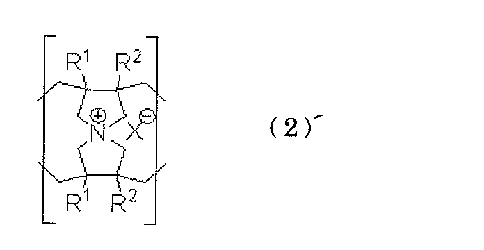
- an anion exchange group can also be provided at the cross-linked site as shown in the following formula (2) ′. .
- the crosslinked structure is most preferably a structure represented by the following formula (2).
- R 1 in ', R 2 and X -, R 1, R 2 and X in each of the formulas (1) - is synonymous, R 5 and R 6, Independently of each other, they are a hydrogen atom, a halogen atom, an alkyl group, or a hydroxyl group.
- R 1 , R 2 , R 5 and R 6 in the above formula (2) are all sterically hindered from the viewpoint of ease of polymerization reaction when synthesizing an anion exchange resin (polymer crosslinked product). Most preferably, it is a hydrogen atom that hardly causes a delay in polymerization rate.
- Z in the formula (2) is represented by the following formula (where n1 is an integer of 0 to 10, and n2, n3, n4, n5 and n6 are each independently an integer of 1 to 10). Means the group indicated.
- Z is not particularly limited as long as it is selected from the structures described above, but — (CH 2 ) n1 — or — (CH 2 ) n2 —O— (CH 2 ) n3 — is used from the viewpoint of durability in an alkaline atmosphere. And is most preferably — (CH 2 ) n1 —.
- n1 representing the ethylene chain length represents an integer of 0 to 10
- n2 to n6 each independently represents an integer of 1 to 10.
- Z is — (CH 2 ) n1 —
- n1 is particularly preferably an integer of 1 to 6 from the viewpoint of ionic conductivity of the film.
- the combination of the crosslinked structure and the anion exchange group is as follows: The combinations shown below are most preferred.
- the following structure is represented as a repeating unit of a polymer crosslinked body, this structure is an example of a particularly preferable repeating unit.
- the amount of anion exchange groups contained in one unit in other words, a crosslinking
- the molar ratio of the bis (N-methyl-pyrrolidinium) butane skeleton structural unit as the site and the N, N-dimethyl-pyrrolidinium skeleton structural unit as the anion exchange group is not limited to 2.
- the molar ratio is preferably 1:99 to 70:30, particularly 2:98 to 40:60.
- the content of the anion exchange resin in the anion exchange membrane of the present invention varies depending on the type of the microporous film used and cannot be generally defined, but is usually 10 per 100 parts by mass of the microporous film. It is in the range of ⁇ 90 parts by mass, preferably in the range of 20 to 70 parts by mass.
- the anion exchange membrane of the present invention depends on the material of the microporous film as the substrate, the pore diameter and the porosity, and the type and content of the anion exchange resin, etc. It is possible to control physical properties such as capacity, fuel liquid permeability, membrane electrical resistance, and moisture content.
- the anion exchange capacity a high value of usually 0.1 to 3 mmol / g, particularly 0.3 to 2.5 mmol / g can also be realized by measurement by a conventional method.
- the water content can be usually 5 to 90%, more preferably 10 to 80%, and the electrical resistance due to drying, that is, the ionic conductivity can hardly be reduced.
- membrane resistance can be expressed by the value measured by the method shown in Examples below, 0.40 ⁇ ⁇ cm 2 or less, also further reduced and very 0.25 ohms ⁇ cm 2 or less.
- the anion exchange membrane of the present invention uses the above-described special anion exchange resin, a conventional anion exchange resin in which a quaternary ammonium base is directly bonded to the benzylic carbon of the aromatic ring is used. Higher alkali resistance than an anion exchange membrane.
- the anion exchange capacity retention rate after being held in an aqueous solution having an ethanol content of 12 mass% and a potassium hydroxide concentration of 10 mass% at a high temperature of 80 ° C. for 500 hours is 90% or more, preferably 95% or more.
- the anion exchange membrane of the present invention exhibits high alkali resistance as described above, when a direct liquid fuel type fuel cell is produced using the anion exchange membrane of the present invention, the fuel cell further exhibits a reaction activity.
- anion exchange membrane of the present invention can be suitably produced by a method comprising the following steps (1) and (2).
- the anion exchange resin used in the anion exchange membrane of the present invention can be obtained by polymerizing and crosslinking a monomer composition containing a monomer component containing a diallylammonium salt and a crosslinking agent.
- the monomer composition is introduced into the voids of a microporous film made of a resin that is insoluble in water, and then polymerized and crosslinked, whereby the microporous film and the anion exchange resin are And an anion exchange membrane of the present invention.
- various materials and polymerization methods used in the method of the present invention will be described in detail.
- the monomer component used in the process of the present invention comprises a diallylammonium salt.
- the diallylammonium salt means a quaternary ammonium salt having two allylic double bonds as a polymerizable group in the molecule.
- the diallylammonium salt functions as a polymerizable monomer (monomer), but in the present invention, the diallylammonium salt is represented by the following formula (3) from the viewpoint of polymerizability and availability. It is preferable to use ammonium salts.
- R 1, R 2, R 3, R 4 and X - is each R 1, R 2, R 3 in the formula (1), R 4 and X - is synonymous.
- ammonium salt represented by the above formula (3) that can be suitably used in the present invention include diallyldimethylammonium chloride, diallyldiethylammonium chloride, diallylethylmethylammonium chloride, and counter anions of these quaternary ammonium salts. Can be substituted for iodine ion or bromine ion. Further, diallyl pyrrolidinium salt, diallyl piperidinium salt, etc. in which R 3 and R 4 are linked to form a ring can be suitably used, and in particular, 1,1-diallyl-3, which has a structure without ⁇ -hydrogen.
- 3,4,4-tetramethylpyrrolidinium salt, 1,1-diallyl-3,3,5,5-tetramethylpiperidinium salt, etc. are particularly preferred in terms of inhibiting Hoffman elimination of hydroxide salts. It can be suitably used. These can be used singly or as a mixture of a plurality of different types.
- the monomer component used in the present invention may be composed only of diallylammonium salt, but for the purpose of modifying the flexibility of the anion exchange membrane or imparting hydrophobicity, other polymerization is performed. May contain a functional monomer.
- examples of other polymerizable monomers include styrene, acrylonitrile, methylstyrene, acrolein, methyl vinyl ketone, and vinyl biphenyl.
- the proportion of diallylammonium salt in the monomer component is preferably 60% by mass or more, particularly preferably 95% by mass or more.
- the cross-linking agent used in the method of the present invention is not particularly limited as long as it is a compound having a function of cross-linking the monomer component or a polymer thereof. From the viewpoint of solubility in a solvent that dissolves the monomer component, diallylamino is used. It is preferable to use a compound having two groups in the same molecule or a compound in which two amino groups of the compound are quaternary ammonium chloride. The latter compound is particularly preferably used from the viewpoint of high anion exchange capacity. A tetraallyl ammonium salt having four allyl groups in the molecule may produce a bicyclic compound during polymerization and lower the degree of crosslinking, but is useful as a crosslinking agent having the lowest molecular weight.
- the compound having two diallylamino groups in the same molecule include a compound represented by the formula (5) in JP-A No. 2001-302729.
- a compound represented by the following formula (4) is used as a compound in which two amino groups of a compound having two diallylamino groups in the same molecule are converted to quaternary ammonium chloride. Is particularly preferred.
- R 1 , R 2 , R 5 , R 6 , Z and X ⁇ are the same as those in the formula (2).
- Z is preferably — (CH 2 ) n1 — or — (CH 2 ) n2 —O— (CH 2 ) n3 — from the viewpoint of durability of the obtained anion exchange resin in an alkaline atmosphere.
- — (CH 2 ) n1 — is particularly preferable.
- n1 is preferably an integer of 1 to 10, particularly 1 to 6, from the viewpoints of solubility in a solvent and salt stability.
- Specific examples of the compound represented by the formula (4) that can be suitably used in the present invention include N, N, N ′, N′-tetraallyl-N, N′-dimethylpropanediammonium dichloride, N, N, N ', N'-tetraallyl-N, N'-dimethylbutanediammonium dichloride, N, N, N', N'-tetraallyl-N, N'-dimethylhexanediammonium dichloride N, N, N ′, N′-tetraallyl-N, N′-dimethylheptanediammonium dichloride, N, N, N ′, N′-tetraallyl-N, N′-dimethyloctanediammonium Dichloride, bis (N, N-tetraallyl-N-methylammoniumethyl) ether dichloride, bis (N, N-tetraallyl-N-methylammoniumpropyl) ether dichloride, bis
- the compound represented by the formula (4) is prepared by mixing and heating diallylmethylamine and dihaloalkane in an organic solvent such as toluene at a substance ratio in which diallylmethylamine is at least twice the number of moles of dihaloalkane.
- the reaction can be followed by washing and solvent evaporation.
- the monomer composition used in the present invention contains the monomer component and a crosslinking agent.
- the amount ratio between the monomer component and the crosslinking agent in the monomer composition is such that the obtained anion exchange resin has a sufficient crosslinking density so as not to elute in the use environment and has high ionic conductivity.
- the cross-linking agent: monomer component (molar ratio) is preferably selected from the range of 1:99 to 70:30, and more preferably selected from the range of 2:98 to 40:60.
- the monomer composition preferably contains a polymerization initiator.
- the polymerization initiator may be appropriately determined from known polymerization initiators such as organic peroxides and azo compounds depending on the composition of the monomer component and the type of the crosslinking agent. From the viewpoint of solubility, ammonium persulfate, persulfates such as potassium persulfate, and water-soluble azo compounds are preferably used.
- the amount of the polymerization initiator is not particularly limited as long as it is a sufficient amount for the polymerization reaction of the monomer composition to proceed. Generally, the amount of the polymerization initiator is 1 to 50 masses per 100 mass parts of the total amount of the monomer components and the crosslinking agent. 2 to 30 parts by mass is preferable.
- the monomer composition is preferably used as a solution from the viewpoint that the respective constituent components are uniformly mixed.
- the solvent is not particularly limited as long as it is inactive with respect to the monomer component, the crosslinking agent and the polymerization initiator added as necessary, and can dissolve all of them.
- the solvent preferably used include toluene, dimethylformamide, dimethyl sulfoxide, methanol, ethanol, propanol, butanol, water, ethyl acetate, tetrahydrofuran, acetonitrile, chloroform, acetone and the like.
- the introduction accelerator may be appropriately selected from water-soluble organic solvents having permeability to the microporous film according to the type of the microporous film to be used.
- having permeability to a microporous film means that the microporous film is easily wetted, for example, when both are brought into contact with each other, the solvent easily penetrates into the void without being repelled (in other words, the pores are formed). Through to the other side).
- a polyolefin resin when used for the microporous film, it tends to get wet easily with an organic solvent having a low dielectric constant.
- an organic solvent having a low dielectric constant has a low affinity with the mixed solution.
- the introduction accelerator is preferably a water-soluble organic solvent having a dielectric constant of 15 or more, and acetone, methanol, ethanol, propanol and butanol are preferably used.
- alcohols are preferably used for the reason that the viscosity of the solution can be easily adjusted to a viscosity that is easy to handle, is present in the reaction field even during the polymerization, and can impart an appropriate water retention to the polymer.
- the solvent of the monomer composition may have an action as an introduction accelerator.
- an introduction accelerator it depends on the material of the microporous film, acetone, methanol, ethanol, propanol, and butanol function as a solvent and an introduction accelerator.
- acetone, methanol, ethanol, propanol, and butanol function as a solvent and an introduction accelerator.
- the use amount of the introduction accelerator described later means the total amount of the solvent having an action as the introduction accelerator and other introduction accelerators added as necessary.
- the amount of the solvent used is not particularly limited as long as it is an amount capable of dissolving the monomer component and the crosslinking agent.
- the total mass of the monomer component and the crosslinking agent is 100 parts by mass.
- it is usually 10 to 1000 parts by mass, but is preferably in the range of 20 to 200 parts by mass since the exchange capacity of the obtained anion exchange membrane can be increased.
- the viscosity of the monomer composition solution is set to a steady viscosity value of 0.5 by a B-type rotational viscometer at 25 ° C. from the viewpoint of easy introduction when the monomer composition is introduced into the voids of the microporous film.
- the range is preferably 001 to 1 Pa ⁇ s, and more preferably 0.001 to 0.1 Pa ⁇ s.
- the above-described monomer composition is introduced into the voids of the microporous film.
- the monomer composition is preferably introduced into the voids of the microporous film as a uniform mixture, and for that purpose, it is preferably introduced in the form of a uniform solution.
- the main component of the monomer composition is a salt. Therefore, an aqueous solution is most preferable in order to obtain a uniform solution.
- a resin insoluble in water is difficult to wet with water, it is difficult to introduce an aqueous solution into the voids of such a microporous film made of resin.
- a method for forcibly introducing a monomer composition composed of an aqueous solution into the voids of the porous film there is a method in which the pores of the porous film are brought into a vacuum or a state close thereto by vacuum degassing and then contacted with the aqueous solution.
- this method is because the operation by the vacuum degassing is complicated, the filling takes a long time, and special equipment such as a vacuum chamber is necessary, so that continuous processing is difficult. It is not a practical method.
- the operation is simple and the monomer composition can be efficiently introduced into the voids of the microporous film, the inside of the voids of the microporous film in the step (1).
- a first raw material solution comprising a solution in which the monomer component and the crosslinking agent are dissolved in a mixed solvent of an organic solvent and the introduction accelerator and having permeability to the microporous film is prepared, and the microporous film is prepared.
- the amount of the introduction accelerator used in the first raw material solution is 1 to 200 parts by mass with respect to a total of 100 parts by mass of the monomer component and the crosslinking agent, although it depends on the type of the microporous film. Preferably there is.
- the amount is less than 1 part by mass, the mixed solution is difficult to get wet with the microporous film, and when the amount is more than 200 parts by weight, the ratio of the monomer component and the crosslinking agent in the mixed solution is low. Membrane exchange capacity tends to be low.
- the suitable usage-amount of the introduction promoter contained in said 1st raw material solution changes with kinds of introduction promoter.
- the introduction accelerator is methanol
- it is usually 60 to 200 parts by weight, preferably 80 to 120 parts by weight, and ethanol, with respect to 100 parts by weight in total of the monomer component and the crosslinking agent.
- it is 40 to 100 parts by mass, preferably 50 to 90 parts by mass on the same basis, and in the case of butanol, it is usually 1 to 50 parts by mass, preferably 2 to 20 parts by mass on the same basis.
- the introduction method further includes the following step (1b) or the following step (1b ′) because the high-concentration monomer composition can be more efficiently introduced into the voids. More preferably it comprises.
- the concentration of the solute can be increased as the proportion of water in the solvent increases.
- the permeability to the porous film is higher as the proportion of water in the solvent is smaller and the proportion of the introduction accelerator is higher. Therefore, when only the first raw material solution having high permeability is used, it is difficult to increase the amount of the solute component introduced into the void portion.
- the step (1b) or (1b ′) When a method including a process is adopted, it is possible to introduce more solute components into the voids by gradually replacing the solution once introduced into the voids with a raw material solution having a higher solute concentration. It becomes.
- each raw material solution to be contacted with the microporous film is referred to as “nth (n is a natural number) raw material solution” according to the order of contact.
- the amount of the introduced promoter contained in the raw material solution of the first n (expressed in parts by weight per 100 total parts by weight of the monomer components and the crosslinking agent.
- Q n the fine immediately before The amount of the introduction accelerator contained in the “(n-1) raw material solution” brought into contact with the porous film (expressed in parts by mass with respect to 100 parts by mass in total of the monomer component and the crosslinking agent.
- Q n-1 In terms of the ratio (Q n / Q n-1 ), it is preferably 0.9 to 0.2, particularly preferably 0.8 to 0.4.
- the number of raw material solutions to be prepared is preferably 2 to 5, particularly 2 or 3, and the last used raw material solution is the above-mentioned introduction solution.
- the monomer composition introduced into the voids of the porous film in the step (1) is polymerized and crosslinked.
- the polymerization / crosslinking method is not particularly limited, and a known method such as radical polymerization or ionic polymerization may be appropriately selected depending on the composition of the monomer components used, the type of crosslinking agent, and the type of polymerization initiator. Good. In general, radical polymerization is preferably used because of easy control.
- a polymerization method by heating is generally employed.
- the polymerization temperature is not particularly limited, but is generally 30 to 120 ° C, preferably 40 to 100 ° C.
- the polymerization time is preferably 10 minutes to 10 hours.
- an anion exchange membrane having a uniform and thin thickness meaning that it is not too thick with the same thickness as that of the microporous film as a base material
- the thickness of the anion exchange membrane is preferably thinner from the viewpoint that the membrane resistance when used as an ion exchange membrane for a polymer electrolyte fuel cell can be reduced.
- the thickness of the microporous film used as a substrate The thickness is preferably 0.5 to 20 ⁇ m, more preferably 1 to 10 ⁇ m thicker. From the viewpoint of the balance between electric resistance and strength when used as a fuel cell membrane, it is preferably 10.5 to 140 ⁇ m, particularly preferably 11 to 80 ⁇ m, and most preferably 16 to 60 ⁇ m.
- the thickness uniformity can be determined by using a film thickness meter (for example, a Digimatic indicator manufactured by Mitutoyo Corporation) for an anion exchange membrane in a dry state or a wet state, and film thickness at any 10 points in the region excluding the peripheral portion. It is preferable that the value when the thickness is measured is within a range of ⁇ 5 ⁇ m, particularly within a range of ⁇ 2 ⁇ m, based on the average thickness of 10 points.
- the anion exchange membrane produced in this way is washed, further changed the type of anion X ⁇ , and cut as necessary.
- the counter anion of the anion exchange membrane obtained by the above method is usually a halide ion.
- the anion exchange membrane of the present invention is used as a hydroxide ion conductive membrane for fuel cells, it is preferable to exchange counter ions with hydroxide ions from the viewpoint of increasing the output of the fuel cell.
- the counter ion of the anion exchange membrane obtained as described above is added to the hydroxide ion and ion-exchanged to carbonate ion and / or bicarbonate ion, or a mixture thereof. This is preferable in that it is easy to obtain a high output of the battery.
- the anion exchange membrane is usually subjected to hydroxylation such as sodium hydroxide aqueous solution or potassium hydroxide aqueous solution.
- hydroxylation such as sodium hydroxide aqueous solution or potassium hydroxide aqueous solution.
- a method of immersing in an aqueous alkali solution or an aqueous carbonate solution such as sodium carbonate, potassium carbonate, sodium bicarbonate, potassium bicarbonate is employed.
- the concentration of the alkali hydroxide aqueous solution or the carbonate aqueous solution is not particularly limited, and is about 0.1 to 2 mol ⁇ L ⁇ 1
- the immersion temperature is 5 to 60 ° C.
- the immersion time is 0.5 to About 24 hours.
- Ion exchange membrane for solid polymer fuel cells-Gas diffusion electrode assembly When the anion exchange membrane of the present invention is used for a fuel cell, the anion exchange membrane of the present invention is usually used as a fuel cell diaphragm, and the fuel chamber side gas diffusion electrode and the oxidant chamber side are respectively provided on both sides thereof.
- An electrolyte membrane-electrode assembly in which a gas diffusion electrode is bonded may be used.
- Such an electrolyte membrane-electrode assembly is prepared by adding a binder or a dispersion medium to the electrode catalyst as necessary to obtain a paste-like composition, which is roll-molded as it is or a support layer material such as carbon paper.
- Add ion conductivity-imparting agent and, if necessary, binder or dispersion medium to make a paste-like composition, which is applied on a support layer material such as carbon paper, or applied to a blank for a fuel cell It can be suitably produced by a method of transferring onto a diaphragm or directly applying onto a diaphragm for a fuel cell and then drying, followed by thermocompression bonding with a solid polymer electrolyte membrane.
- a molding comprising a composition containing two or more organic compounds that can be cross-linked by being brought into contact with each other to form an ion exchange resin, and an electrode catalyst.
- the two or more organic compounds contained in the molded body may be cross-linked to form a gas diffusion electrode, which may be bonded to both surfaces of the fuel cell membrane of the present invention.
- ion conductivity-imparting agent examples include hydrocarbon polymer elastomers having an anion exchange group in the molecule and hardly soluble in water and methanol, as disclosed in JP-A-2002-367626.
- an ion conductivity-imparting agent for a gas diffusion electrode of a polymer fuel cell characterized by comprising a solution or a suspension thereof, is preferably used.
- Electrode catalyst platinum, gold, silver, palladium, iridium, rhodium, ruthenium, tin, iron, cobalt that promotes oxidation reaction of oxygen and reduction reaction of oxygen, which are used as electrode catalysts in conventional gas diffusion electrodes
- metal particles such as nickel, molybdenum, tungsten, vanadium, or alloys thereof can be used without limitation, it is preferable to use a transition metal catalyst from the viewpoint of cost.
- These catalysts may be used after being supported on a conductive agent in advance.
- the conductive agent is not particularly limited as long as it is an electronic conductive material.
- carbon black such as furnace black and acetylene black, activated carbon, graphite and the like are generally used alone or in combination. is there.
- the MEA of the present invention when fuel and water are supplied to the fuel chamber of the fuel cell, and the water supplied to the fuel chamber is supplied to the oxidant chamber through the electrolyte membrane-electrode assembly.
- Active against fuel as an electrode catalyst contained in an electrode (fuel chamber side electrode) coupled to one surface of a fuel cell diaphragm to prevent a decrease in output caused by fuel permeating with water
- an electrode catalyst contained in an electrode (oxidant chamber side electrode) coupled to the other surface an electrode catalyst whose activity against the fuel is lower than that of the electrode catalyst contained in the fuel chamber side electrode is used. It is preferable to do.
- the activity of the electrode catalyst contained in the oxidant chamber side electrode with respect to the fuel is preferably 1/10 or less, particularly preferably 1/100 or less, of the activity of the electrode catalyst contained in the fuel chamber side electrode with respect to the fuel. / 1000 or less is most preferable.
- Such a catalyst can be easily selected by performing a simple activity test for each type of fuel used.
- the fuel cell having the anion exchange membrane of the present invention as a fuel cell membrane has the basic structure shown in FIG. 1, that is, a fuel chamber and an oxidant chamber partitioned by MEA.
- the fuel chamber and the oxidant chamber each have one electrode of the MEA, and the fuel and the hydroxide are supplied to the fuel chamber by supplying the fuel to the fuel chamber.
- a polymer electrolyte fuel cell is generally used which reacts with ions, supplies water and an oxidant to the oxidant chamber, and reacts them with an electrode present on the oxidant chamber side.
- the use of the anion exchange membrane of the present invention is not limited to such a type of fuel cell, and can naturally be applied to fuel cells having other known structures.
- methanol is the most common, but ethanol, ethylene glycol, dimethyl ether, hydrazine and the like exhibit the same excellent effect.
- These fuels may be supplied to the fuel chamber as they are, but are preferably supplied in an aqueous solution from the viewpoint of ease of handling and safety.
- the polymer electrolyte fuel cell of the present invention uses the anion exchange membrane of the present invention having high alkali resistance as a fuel cell membrane, high output is obtained by adding alkali such as potassium hydroxide to the fuel. Therefore, even when used under high temperature conditions, its performance is unlikely to deteriorate, and it can be used stably for a long period of time.
- anion exchange membranes obtained in Examples and Comparative Examples and the evaluation items and evaluation methods for fuel cells using the anion exchange membrane as a fuel cell membrane are shown below.
- An anion exchange membrane prepared by the method described in Examples or Comparative Examples was allowed to stand for 24 hours or more in the air in a dry state, and was cut after being moistened with 40 ° C. ion exchange water.
- a strip-shaped anion exchange membrane having a length of 6 cm and a length of 2.0 cm was prepared.
- an insulating substrate in which five platinum wires having a line width of 0.3 mm are arranged in a straight line parallel to the lateral direction (the same direction as the lateral direction of the anion exchange membrane) is prepared.
- a measurement sample was prepared by pressing a platinum wire against the anion exchange membrane.
- a measurement sample was prepared by pressing against a platinum wire. At this time, the anion exchange membrane used for the measurement was obtained in the following Examples and Comparative Examples and then left in the air in a dry state for 24 hours or more.
- samples for measurement a plurality of samples in which the distance between platinum wires was changed to 0.5 to 2.0 cm was prepared.
- an oxidant chamber side gas diffusion electrode was prepared in the same manner as the fuel chamber side diffusion electrode using carbon black carrying 50% by mass of platinum.
- the fuel chamber side diffusion electrode and the oxidant chamber side gas diffusion electrode are set on both surfaces of the anion exchange membrane (fuel cell diaphragm) to be measured, respectively, and hot pressed for 100 seconds at 100 ° C. under a pressure of 5 MPa. And left at room temperature for 2 minutes.
- the obtained anion exchange membrane-electrode assembly was allowed to stand in the atmosphere for 24 hours, and was then incorporated into the fuel cell having the structure shown in FIG. 1, set to a fuel cell temperature of 50 ° C., and the KOH on the fuel electrode side.
- A Microporous film made of polyethylene (film thickness 25 ⁇ m, average pore diameter 0.03 ⁇ m, porosity 40%)
- DADM diallyldimethylammonium chloride
- DADE diallyldiethylammonium chloride
- DAME diallylethylmethylammonium chloride
- C3 N, N, N ′, N'-tetraallyl-N, N'-dimethylpropanediammonium dichloride
- C4 N, N, N ', N'-tetraallyl-N, N'-dimethylbutanediammonium dichloride
- C6 N, N , N ′, N′-Tetraallyl-N, N′-dimethylhexanediammonium dichloride
- C0 Tetraallylammonium bromide APS
- Example 1 According to the composition table shown in Table 1, various monomers, a cross-linking agent, a polymerization initiator, and a solvent (water) were mixed and stirred to obtain a monomer composition aqueous solution MS 0 not containing methanol as an introduction accelerator. Separately, 100 parts by mass and 50 parts by mass of methanol, which is an introduction accelerator, were mixed and stirred in an aqueous monomer composition solution (without methanol) prepared in the same manner, and the monomer composition diluted MS 100 and MS were stirred. 50 was prepared.
- the microporous film A of 20 cm ⁇ 20 cm was taken out after being immersed in the monomer composition dilution MS 100 in a vat for 5 minutes at room temperature, and then taken out in the same manner, and the monomer composition dilution liquid MS 50 and the monomer composition aqueous solution were similarly removed.
- the monomer composition was introduced into the voids of the microporous film by sequentially immersing in MS 0 . Thereafter, both surfaces of the microporous film taken out from the bat were covered with a release material made of a polyester film having a thickness of 100 ⁇ m, and then introduced into the void by heating at 50 ° C. for 5 hours under a nitrogen pressure of 0.3 MPa.
- the monomer component was polymerized and crosslinked.
- the anion exchange membrane of the present invention obtained after polymerization was immersed in methanol for 1 hour, washed, and then immersed in a large excess of 0.5 mol ⁇ L ⁇ 1 -NaOH aqueous solution to convert the counter ion from bromide ion to hydroxylation. Ion exchange to product ions was followed by washing with ion exchange water.
- Various evaluations were performed on the anion exchange resin of the present invention thus obtained. The evaluation results are shown in Table 2.
- Example 2 Example 1 with the monomer composition solution MS 0 in the same manner, with the preparation of a monomer composition diluted MS 100 and MS 50, except that the amount of methanol added to 20 parts by mass in the same manner as in the preparation of the monomer composition diluted MS 100
- the monomer composition dilution MS 20 was prepared.
- the 20 cm ⁇ 20 cm microporous film A was taken out after being immersed in the monomer composition dilution MS 100 in a vat at room temperature for 10 minutes, and then taken out in the same manner, and the monomer composition dilution liquid MS 50 and the monomer composition dilution liquid MS 20 were further removed.
- Example 3 In the same manner as monomer composition solution MS 0, while preparing a monomer composition diluted MS 100 and MS 50, added amount of methanol to others are of monomer composition diluted MS 100 to 70 parts by weight and 20 parts by weight Monomer composition dilution MS 70 and monomer composition dilution MS 20 were prepared in the same manner as the preparation.
- Example 4 An anion exchange membrane was prepared, treated and evaluated in the same manner as in Example 1 except that the monomer composition was prepared according to the composition table shown in Table 1. The results are also shown in Table 2.
- Example 9 3 parts by mass of 1-butanol was added as an introduction accelerator to the monomer composition aqueous solution MS 0 to obtain a uniform solution. Next, a 20 cm ⁇ 20 cm microporous film A was taken out after being immersed in a monomer solution at room temperature, and the anion exchange membrane was prepared in the same manner as in Example 2 except that the monomer composition was introduced into the voids of the microporous film. Processing and evaluation were performed. The results are also shown in Table 2.
- Example 10 The monomer composition was introduced into the voids of the microporous film A in the same manner as in Example 1 except that the monomer composition was only taken out after being immersed in the monomer composition diluted MS 100 in a vat for 5 minutes at room temperature.
- the anion exchange membrane was prepared, processed and evaluated. The results are also shown in Table 2.
- the obtained film was immersed in an aqueous solution containing 6% by weight trimethylamine and 25% by weight acetone at room temperature for 16 hours, and then immersed in a large excess of 0.5 mol ⁇ L ⁇ 1 -NaOH aqueous solution. Ions were ion-exchanged from chloride ions to hydroxide ions and then washed with ion-exchanged water to obtain an anion exchange membrane.
- the obtained anion exchange membrane was evaluated in the same manner as in Example 1. The results are also shown in Table 2.
- Example 11 83 parts by mass of 1,1-diallyl-3,3,5,5-tetramethylpiperidinium bromide, 17 parts by mass of tetraallylammonium bromide, and 13 parts by mass of APS were dissolved in 42 parts by mass of ion-exchanged water as an introduction accelerator. 8 parts by mass of 1-butanol was added to obtain a uniform solution. Next, a 20 cm ⁇ 20 cm microporous film A was immersed in the monomer solution at room temperature and then taken out, and the monomer composition was introduced into the voids of the microporous film.
- both surfaces of the microporous film into which the monomer has been introduced are coated with a release material made of a polyester film having a thickness of 100 ⁇ m, and then heated under nitrogen pressure of 0.4 MPa for 2 hours at 60 ° C. and 24 hours at 70 ° C.
- the monomer component introduced into the void was polymerized and crosslinked.
- the anion exchange membrane of the present invention obtained after polymerization was immersed in methanol for 1 hour, washed, and then immersed in a large excess of 0.5 mol ⁇ L ⁇ 1 -NaOH aqueous solution to convert the counter ion from bromide ion to hydroxylation. Ion exchange to product ions was followed by washing with ion exchange water.
- the obtained membrane had an ion exchange capacity of 0.9 mmol / g-dry membrane, and the ion exchange capacity retention after the deterioration test was 95%.
- FIG. 1 is a conceptual diagram showing a basic structure of a polymer electrolyte fuel cell.
Landscapes
- Chemical & Material Sciences (AREA)
- Engineering & Computer Science (AREA)
- Manufacturing & Machinery (AREA)
- Chemical Kinetics & Catalysis (AREA)
- General Chemical & Material Sciences (AREA)
- Sustainable Development (AREA)
- Electrochemistry (AREA)
- Sustainable Energy (AREA)
- Life Sciences & Earth Sciences (AREA)
- Organic Chemistry (AREA)
- Health & Medical Sciences (AREA)
- Polymers & Plastics (AREA)
- Medicinal Chemistry (AREA)
- Crystallography & Structural Chemistry (AREA)
- Materials Engineering (AREA)
- Composite Materials (AREA)
- Inorganic Chemistry (AREA)
- Physics & Mathematics (AREA)
- Spectroscopy & Molecular Physics (AREA)
- Manufacture Of Macromolecular Shaped Articles (AREA)
- Addition Polymer Or Copolymer, Post-Treatments, Or Chemical Modifications (AREA)
- Conductive Materials (AREA)
Abstract
Description
(i) 反応場が強酸性のため、貴金属触媒しか使用できず、また、パーフルオロカーボンスルホン酸樹脂膜も高価であり、コストダウンに限界がある。
(ii) 保水力が充分でないため水の補給が必要となる。
(iii) 物理的な強度が低いため薄膜化による電気抵抗の低減が困難である。
高分子架橋体の架橋密度が高い場合には熱可塑性を示し難くなるため、ホットプレスなどの熱処理により成膜することは困難である。そのため熱処理により成膜するためには、ある程度の熱可塑性を有する必要があり、架橋密度についても自ずと制限があると思われる。また、熱処理によって、高分子架橋体を薄く(たとえば50μmといった厚さで)、且つ、膜厚の均一性が高い膜を成膜することは極めて困難である。燃料電池用の隔膜としての使用を考えた場合、膜厚が厚いことは膜抵抗が高くなることを意味し、好ましくない。また、厚さの均一性が低いことは性能の不安定さにつながり、好ましくない。さらに、このようにして得られた膜は、通常の状態である程度の強度を有していたとしても、基材を用いていないために、燃料電池用の隔膜として使用した場合には、水や液体燃料などによって膨潤して強度が低下する可能性がある。
1. 水に対して不溶な樹脂からなる多孔質フィルムと、該多孔質フィルムの空隙を充塞する陰イオン交換樹脂とを含んでなる陰イオン交換膜であって、前記陰イオン交換樹脂は、下記式(1)で表される陰イオン交換基を有する高分子架橋体を含む陰イオン交換膜。

2. 前記高分子架橋体が下記式(2)又は(2)´で示される架橋部位を有する前記1に記載の陰イオン交換膜。

R5及びR6は、相互に独立して水素原子、ハロゲン原子、炭素数1~10のアルキル基、または水酸基であり、
Zは下記式で示される基である。

3. 前記1又は2に記載の陰イオン交換膜を製造する方法であって、
(1) ジアリルアンモニウム塩を含むモノマー成分及び架橋剤を含んでなるモノマー組成物を水に対して不溶な樹脂からなる微多孔フィルムの空隙内に導入する工程と、
(2) 前記微多孔フィルムの空隙部に導入された前記モノマー組成物を重合及び架橋させる工程と、
を含む陰イオン交換膜の製造方法。
前記3~6の方法によれば、上記したような優れた特徴を有する本発明の陰イオン交換膜を効率良く製造することができる。
前記1及び/又は2の本発明の陰イオン交換膜を用いた前記9の燃料電池は、触媒活性がより高くなる(別言すれば高出力が得られる)高温において、長期間運転しても性能が低下し難く、高い耐久性を有する。そして、上記燃料電池では、陽イオン交換膜を用いた燃料電池で問題であった前記(i)~(iii)の問題も回避可能である。
(水に対して不溶な樹脂からなる微多孔フィルム)
本発明のイオン交換膜は水に対して不溶な樹脂からなる微多孔フィルムと、該微多孔フィルムの空隙を充塞する特定の陰イオン交換樹脂とを含んでなる。
塩化ビニル系樹脂:ポリ塩化ビニル、塩化ビニル-酢酸ビニル共重合体、塩化ビニル-塩化ビニリデン共重合体、塩化ビニル-オレフィン共重合体等;
フッ素系樹脂:ポリテトラフルオロエチレン、ポリクロロトリフルオロエチレン、ポリフッ化ビニリデン、テトラフルオロエチレン-ヘキサフルオロプロピレン共重合体、テトラフロオロエチレン-ペルフロオロアルキルビニルエーテル共重合体、テトラフルオロエチレン-エチレン共重合体等;
ポリアミド樹脂:ナイロン6、ナイロン66等。
本発明の陰イオン交換膜は、前記微多孔フィルムの空隙が下記式(1)で表される陰イオン交換基を有する高分子架橋体からなる陰イオン交換樹脂で充塞されてなる。ここで、空隙とは微多孔フィルムの孔によって形成させるものであり、充塞するとは、膜の表裏に穿通する孔を塞ぐように満たすことを意味する。陰イオン交換樹脂は、前記孔を塞いでいればその存在形態は特に限定されない。たとえば膜の全体又は一部に於いて、孔の一部を満たしている状態であってよく、また、孔からあふれて膜の表裏を覆うように存在していてもよい。

また、R3とR4は互いにつながって環状構造を持っても良く、特に3,3,5,5-テトラメチルピペリジニウム骨格は、β-水素が無い構造であるため、水酸化4級アンモニウム塩のホフマン脱離反応が抑制できるため、より好ましい。
なお、後述するように、前記陰イオン交換樹脂は、ジアリルアンモニウム塩を含むモノマー成分及び架橋剤を含んでなるモノマー組成物を重合及び架橋させることによって得ることができるものである。前記式(1)で表される5員環構造(ピロリジン構造)を有する陰イオン交換基は、ジアリルアンモニウム塩を含むモノマー成分が重合する際に形成されるものであるが、該重合に際しては、反応機構上、前記式(1)で表される陰イオン交換基以外に下記式に示されるような6員環構造(ピペリジン構造)を有する陰イオン交換基が形成される可能性もある。そして、このような陰イオン交換基も耐アルカリ性や耐熱性に関しては前記式(1)で示される陰イオン交換基と同等であると考えられる。したがって、前記陰イオン交換樹脂には、このような陰イオン交換基が含まれていてもよい。


本発明の陰イオン交換膜は、下記工程(1)及び(2)を含んでなる方法により好適に製造することができる。
(1) ジアリルアンモニウム塩を含むモノマー成分及び架橋剤を含んでなるモノマー組成物を水に対して不溶な樹脂からなる微多孔フィルムの空隙内に導入する工程
(2) 前記微多孔フィルムの空隙部に導入された前記モノマー組成物を重合及び架橋させる工程
本発明の方法で使用するモノマー成分は、ジアリルアンモニウム塩を含んで成る。ここでジアリルアンモニウム塩とは、重合性基としてのアリル性二重結合を分子内に2つ有する四級アンモニウム塩を意味する。該ジアリルアンモニウム塩は重合性単量体(モノマー)として機能するものであるが、本発明においては、重合性及び入手容易性の観点から、ジアリルアンモニウム塩としては、下記式(3)で表されるアンモニウム塩を使用することが好適である。

本発明の方法で使用する架橋剤は、上記モノマー成分またはその重合物を架橋させる機能を有する化合物であれば特に限定されないが、上記モノマー成分を溶解する溶媒への溶解性の観点から、ジアリルアミノ基を同一分子内に2つ有する化合物または、該化合物の2つのアミノ基が四級アンモニウム塩化された化合物を使用するのが好適である。また、陰イオン交換容量の高さの観点から後者の化合物を使用するのが特に好ましい。また、アリル基を分子内に四つ有するテトラアリルアンモニウム塩は、重合時に二環性化合物を生成して架橋度が下がる可能性があるが、最も分子量が低い架橋剤として有用である。

本発明で使用するモノマー組成物は前記モノマー成分および架橋剤を含む。該モノマー組成物におけるモノマー成分と架橋剤との量比は、得られる陰イオン交換樹脂が、使用環境において溶出しなくなるような十分な架橋密度を有し、且つ高いイオン伝導性を有するという観点から、架橋剤:モノマー成分(モル比)で表して1:99~70:30の範囲から選択することが好ましく、2:98~40:60の範囲から選択することがより好ましい。
本発明においては、モノマー組成物の溶媒が導入促進剤としての作用を兼ね備えていてもよい。微多孔フィルムの材質にもよるが、アセトン、メタノール、エタノール、プロパノール、ブタノールは、溶媒および導入促進剤としての作用を有する。溶媒として、導入促進剤としての作用を有するものを用いる場合には、別途導入促進剤を添加しなくてもよく、また添加してもよいが、導入促進剤としての作用を兼備する場合には、後述する導入促進剤の使用量は、導入促進剤としての作用を有する溶媒および必要に応じ添加される他の導入促進剤の合計量を意味する。
発明の製造方法では、工程(1)において、前述のモノマー組成物を前記微多孔フィルムの空隙に導入する。均質な陰イオン交換膜を得るためには、上記モノマー組成物は均一な混合物として微多孔フィルムの空隙内に導入することが好ましく、そのためには均一溶液の形態で導入することが好ましい。好適な形態においてモノマー組成物の主成分は塩となるため、均一な溶液とするためには水溶液にすることが最も好ましい。しかしながら、水に不溶な樹脂は水には濡れ難いため、水溶液をこのような樹脂製の微多孔フィルムの空隙内に導入することは困難である。たとえば、水溶液から成るモノマー組成物を多孔質フィルムの空隙部に強制的に導入させる方法として、減圧脱気により多孔質フィルムの空孔部を真空若しくはそれに近い状態としてから水溶液と接触させる方法などが考えられるが、該方法は、減圧脱気による方法は操作が煩雑であること、充填に長時間を要すること、真空チャンバーなど特殊な設備が必要であるため連続処理が困難であるなどの理由から実用的な方法とはいえない。
このとき、前記第一の原料溶液における前記導入促進剤の使用量は、前記微多孔フィルムの種類にもよるが、前記モノマー成分及び架橋剤の合計100質量部に対して1~200質量部であることが好ましい。1質量部未満では該混合溶液が前記微多孔フィルムには濡れ難くなり、また200質量部より多い場合には該混合溶液に占めるモノマー成分及び架橋剤の割合が低くなるため、得られる陰イオン交換膜の交換容量が低くなる傾向がある。
また、前記第一の原料溶液に含まれる導入促進剤の好適な使用量は導入促進剤の種類によって異なる。たとえば、導入促進剤がメタノールである場合は、通常、前記モノマー成分及び架橋剤の合計100質量部に対して60~200質量部、好ましくは80~120質量部であり、エタノールである場合は、通常、同基準で40~100質量部、好ましくは50~90質量部であり、ブタノールの場合は、通常、同基準で1~50質量部、好ましくは2~20質量部である。
工程(1b):前記導入促進剤と、前記モノマー成分及び架橋剤の溶液との混合溶液からなり、該混合溶液における前記導入促進剤の濃度は前記第一の原料溶液における導入促進剤の濃度よりも低く、且つ前記モノマー成分の濃度は前記第一の原料溶液における前記モノマー濃度より高い第二の原料溶液を準備し、工程(1a)において前記第一の原料溶液と接触させた前記微多孔フィルムと前記第二の原料溶液とを接触させる工程;
工程(1b’):前記導入促進剤と、前記モノマー成分及び架橋剤の溶液との混合溶液からなる複数の原料溶液であって、これら原料溶液における前記導入促進剤の濃度は何れも前記第一の原料溶液における導入促進剤の濃度よりも順次低くなると共にこれら原料溶液における前記モノマー成分の濃度は何れも前記第一の原料溶液におけるモノマー成分の濃度よりも順次高くなる複数の原料溶液を準備し、工程(1a)において前記第一の原料溶液と接触させた前記微多孔フィルムと前記各原料溶液とを、原料溶液における前記導入促進剤の濃度が高い順に、順次接触させる工程。
このとき、前記工程(1b)又は(1b’)において、前記微多孔フィルムと接触させる各原料溶液を、接触させる順番に応じて「第n(nは自然数である)の原料溶液」と呼ぶ場合、当該第nの原料溶液に含まれる前記導入促進剤の量(前記モノマー成分及び架橋剤の合計100質量部に対する質量部で表す。以下、Qnと略記する。)は、その直前に前記微多孔フィルムと接触させた「第(n-1)の原料溶液」に含まれる前記導入促進剤の量(前記モノマー成分及び架橋剤の合計100質量部に対する質量部で表す。以下、Qn-1と略記する。)に対する比(Qn/Qn-1)で表して、0.9~0.2、特に0.8~0.4とすることが好ましい。ただし、前記工程(1b)において、第1の原料溶液に含まれる前記導入促進剤の量Q1が60~1質量部であるときは、Q2は0質量部であってもよく、Q2/Q1=0.5~0とするのが好ましい。また、前記工程(1b’)においては、効率性の観点から、準備する複数の原料溶液の数を2~5、特に2又は3とすることが好ましく、最後に使用する原料溶液は、前記導入促進剤を含んでいない(Qn=0質量部である)ものであってもよく、Qn/Qn-1=0.5~0とすることが好ましい。
本発明の方法では、前記工程(1)によって多孔質フィルムの空隙部に導入されたモノマー組成物を重合及び架橋させる。このとき、重合・架橋方法は特に限定されず、用いたモノマー成分の組成、架橋剤の種類及び重合開始剤の種類に応じて適宜公知の方法、例えばラジカル重合やイオン重合等を適宜選択すればよい。一般には制御が容易なことからラジカル重合が好ましく用いられる。例えば重合開始剤としてラジカル重合開始剤である過硫酸アンモニウムや、過硫酸カリウムなどの過硫酸塩、水溶性アゾ系化合物を用いる場合は、加熱による重合方法(熱重合)が一般的に採用される。熱重合させる場合、重合温度は特に制限されないが、一般的には30~120℃、好ましくは40~100℃である。重合時間は、10分~10時間が好ましい。
陰イオン交換膜の厚さは、固体高分子型燃料電池用イオン交換膜として用いたときの膜抵抗を小さくすることができるという観点から薄い方が好ましく、基材として用いた微多孔フィルムの厚さと同じか、それよりも0.5~20μm、特に1~10μm厚いことが好ましい。燃料電池用隔膜として使用したときの電気抵抗と強度とのバランスの観点から10.5~140μmであることが好ましく、11~80μmであることが特に好ましく、16~60μmであることが最も好ましい。また、厚さの均一性は、乾燥状態または湿状態の陰イオン交換膜について膜厚計(例えば、株式会社ミツトヨ製デジマチックインジケータ)を用いて、周縁部を除く領域の任意の10点について膜厚を測定したときの値が、いずれの測定値も10点の平均の厚さを基準として±5μmの範囲内、特に±2μmの範囲内であることが好ましい。
本発明の陰イオン交換膜を燃料電池用に使用する場合には、通常、本発明の陰イオン交換膜を燃料電池用隔膜として用い、その両面にそれぞれ燃料室側ガス拡散電極および酸化剤室側ガス拡散電極を接合させた電解質膜-電極接合体とすればよい。このような電解質膜-電極接合体は、電極触媒に必要に応じて結着剤や分散媒を添加してペースト状の組成物とし、これをそのままロール成型するか又はカーボンペーパー等の支持層材料上に塗布した後に熱処理して層状物を得、その接合面となる表面にイオン伝導性付与剤を塗布した後に必要に応じて乾燥し、燃料電池用隔膜と熱圧着する方法;又は電極触媒にイオン伝導性付与剤及び必要に応じて結着剤や分散媒を添加してペースト状の組成物とし、これをカーボンペーパー等の支持層材料上に塗布するか、ブランクに塗布して燃料電池用隔膜上に転写するか、または燃料電池用隔膜上に直接塗布した後に乾燥させ、その後固体高分子電解質膜と熱圧着する方法などにより好適に製造することができる。また、特開2003-86193号公報に開示されているように、互いに接触することにより架橋してイオン交換樹脂を形成し得る2種以上の有機化合物、及び電極触媒を含有する組成物からなる成形体を得た後に該成形体中に含まれる前記2種以上の有機化合物を架橋させてガス拡散電極を形成し、これを本発明の燃料電池用隔膜の両面に接合しても良い。
電極触媒としては、従来のガス拡散電極において電極触媒として使用されている、水素の酸化反応及び酸素の還元反応を促進する白金、金、銀、パラジウム、イリジウム、ロジウム、ルテニウム、スズ、鉄、コバルト、ニッケル、モリブデン、タングステン、バナジウム、あるいはそれらの合金等の金属粒子が制限なく使用できるが、コストの観点から遷移金属触媒を使用することが好ましい。これら触媒は、予め導電剤に担持させてから使用してもよい。導電剤としては、電子導電性物質であれば特に限定されるものではないが、例えば、ファーネスブラック、アセチレンブラック等のカーボンブラック、活性炭、黒鉛等を単独または混合して使用するのが一般的である。
本発明の陰イオン交換膜を燃料電池用隔膜とした燃料電池としては、前記した図1の基本構造を有するもの、即ち、MEAで仕切られた燃料室と酸化剤室とを有し、該燃料室および該酸化剤室には夫々前記MEAの一方の電極が存在しており、前記燃料室に燃料を供給して該燃料室側に存在する電極で燃料と水酸化物イオンとを反応させ、前記酸化剤室に水及び酸化剤を供して該酸化剤室側に存在する電極でこれらを反応させる固体高分子型燃料電池が一般的である。しかし、本発明の陰イオン交換膜の用途は、このようなタイプの燃料電池に限定されるものではなく、その他の公知の構造を有する燃料電池にも勿論適用することができる。燃料の液体としては、メタノールが最も一般的であるが、その他、エタノール、エチレングリコール、ジメチルエーテル、ヒドラジン等においても同様の優れた効果が発揮される。これら燃料はそのまま燃料室に供給しても良いが、取扱いの容易さや安全性の観点から水溶液で供給することが好ましい。
陰イオン交換膜を、0.5mol・L-1-NaCl水溶液に10時間以上浸漬し、塩化物イオン型とした後、0.2mol・L-1-NaNO3水溶液で硝酸イオン型に置換したときに遊離した塩化物イオンを、硝酸銀水溶液を用いて電位差滴定装置(COMTITE-900、平沼産業株式会社製)で定量した(A mmol)。次に、同じイオン交換膜を0.5mol・L-1-NaCl水溶液に25℃下で4時間以上浸漬し、イオン交換水で十分水洗した後膜を取り出しティッシュペーパー等で表面の水分を拭き取り湿潤時の重さ(Wg)を測定した。さらに膜を60℃で5時間減圧乾燥させその重量を測定した(Dg)。
上記測定値に基づいて、イオン交換容量および含水率を次式により求めた。
陰イオン交換容量=A×1000/D[mmol・g-1-乾燥重量]
含水率=100×(W-D)/D[%]。
実施例または比較例に記載した方法によって調製した陰イオン交換膜を大気中、乾燥状態で24時間以上放置したものを40℃のイオン交換水に湿潤させた後に切断し、横約6cm、縦2.0cmの短冊状の陰イオン交換膜を準備した。次いで、線幅0.3mmの白金線5本を、横方向(陰イオン交換膜の横方向と同じ方向)に対して平行となる直線状に配置した絶縁基板を準備し、該絶縁基板の前記白金線を前記陰イオン交換膜に押し当てることにより測定用試料を作成した。
線幅0.3mmの白金線5本を所定の間隔で互いに離して平行に配置した絶縁基板を用い、40℃のイオン交換水に湿潤した2.0cm幅の短冊状の陰イオン交換膜を前記白金線に押し当てることにより測定用試料を調製した。このとき、測定に用いた陰イオン交換膜は、下記の実施例、比較例で得た後、大気中で乾燥状態で24時間以上放置したものを使用した。また、測定用試料としては、白金線間距離を0.5~2.0cmに変化させた複数の試料を準備した。
上記各測定用試料について、1本目と2本目の白金線間(白金線間隔=0.5cm)、1本目と3本目の白金線間(白金線間隔=1.0cm)、1本目と4本目の白金線間(白金線間隔=1.5cm)および1本目と5本目の白金線間(白金線間隔=2.0cm)についてそれぞれ交流インピーダンスを測定した。x軸に白金線間距離をとりy軸に交流インピーダンスをとって各試料についての測定値をプロットしたときに得られるグラフから抵抗極間勾配(S)を求めると共に、下記式に基づき膜抵抗(R)を求めた。このとき、交流インピーダンスは、測定用試料を40℃、90%RHの恒温恒湿槽中で陰イオン交換膜表面にイオン交換水の水滴が存在する状態に保持し、白金線間に1kHzの交流を印加したときの交流インピーダンスとして測定した。また、膜厚(L)は陰イオン交換膜をイオン交換水で湿潤させて、株式会社ミツトヨ製デジマチックインジケータを用いて測定した。
R :見かけ上の膜抵抗[Ω・cm2]
L :膜厚[cm]
S :抵抗極間勾配[Ω・cm-1]
なお、上記グラフにおいて、白金線間距離と交流インピーダンスとの間には直線関係(比例関係)が成立ち、測定試料における白金線と陰イオン交換膜との間の接触による抵抗(接触抵抗)はy切片として評価され、グラフの傾きから膜の比抵抗を意味する抵抗極間勾配(S)を算出することができる。本測定では、膜抵抗(R)は抵抗極間勾配(S)に基づいて求められているので、上記接触抵抗の影響は排除されている。
対イオンを水酸化物イオン型にした陰イオン交換膜を5cm角の寸法に切り出し、ポリテトラフルオロエチレン製容器に入れ、80℃のオーブン中、エタノール濃度が12質量%で且つ水酸化カリウム濃度が10質量%である水溶液に500時間保持することにより劣化試験を行った。
劣化試験後の陰イオン交換容量を測定し、劣化試験前の陰イオン交換容量に対する劣化試験後の陰イオン交換容量の割合からなる陰イオン交換容量保持率を求め、該陰イオン交換容量保持率をもって耐久性の指標とした。
また、陰イオン交換膜の劣化による燃料電池出力への影響を調べるために、劣化試験後の陰イオン交換膜を隔膜として用いた燃料電池を構成し、下記4)に記載する方法により劣化試験後の出力電圧の測定を行った。
分子量3万、スチレン含量30質量%のクロルメチル化-{ポリスチレン-ポリ(エチレン-ブチレン)-ポリスチレン}トリブロック共重合体をトリメチルアミンで4級化した後、大過剰の0.5mol・L-1-NaOH水溶液中に懸濁して水酸化物イオンにイオン交換した陰イオン交換樹脂(陰イオン交換容量1.4mmol/g)の1-プロパノール溶液(樹脂濃度5質量%)と白金とルテニウム合金触媒(ルテニウム50mol%)50質量%担持のカーボンブラックとを混合したものを、ポリテトラフルオロエチレンで撥水化処理した厚さ100μm、空孔率80%のカーボンペーパー上に、触媒が2mg・cm-2となるように塗布し、80℃で4時間減圧乾燥し、燃料室側拡散電極を製造した。
次に、測定する陰イオン交換膜(燃料電池隔膜)の両面に上記の燃料室側拡散電極および酸化剤室側ガス拡散電極をそれぞれセットし、100℃、圧力5MPaの加圧下で100秒間熱プレスした後、室温で2分間放置した。得られた陰イオン交換膜-電極接合体を大気中で24時間放置した後、これを図1に示す構造の燃料電池セルに組み込んで燃料電池セル温度50℃に設定し、燃料極側にKOHを含有する10質量%エタノール水溶液(KOH濃度5質量%)を、酸化剤極側に大気圧の空気を200ml・min.-1で供給して発電試験を行ない、電流密度0.1A・cm-2におけるセルの端子電圧を測定した。
A:ポリエチレン製微多孔フィルム(膜厚25μm、平均孔径0.03μm、空隙率40%)
DADM:ジアリルジメチルアンモニウムクロリド
DADE:ジアリルジエチルアンモニウムクロリド
DAME:ジアリルエチルメチルアンモニウムクロリド
DAP:1,1-ジアリル-3,3,5,5-テトラメチルピペリジニウムブロマイド
C3:N,N,N',N'-テトラアリル-N,N'-ジメチルプロパンジアンモニウム・2塩化物
C4:N,N,N',N'-テトラアリル-N,N'-ジメチルブタンジアンモニウム・2塩化物
C6:N,N,N',N'-テトラアリル-N,N'-ジメチルヘキサンジアンモニウム・2塩化物
C0:テトラアリルアンモニウムブロマイド
APS:過硫酸アンモニウム
MeOH:メタノール
1-BuOH:1-ブタノール。
表1に示した組成表に従って、各種単量体、架橋剤、重合開始剤及び溶媒(水)を混合、撹拌し、導入促進剤であるメタノールを含まないモノマー組成物水溶液MS0を得た。これとは別に、同様にして調製したモノマー組成物水溶液(メタノールを含まない)に導入促進剤であるメタノールを夫々100質量部および50質量部を混合、撹拌し、モノマー組成物希釈MS100およびMS50を調製した。
次いで20cm×20cmの微多孔フィルムAを、バット(vat)に入れたモノマー組成物希釈MS100に室温で5分間浸漬した後に取り出し、さらに同様にしてモノマー組成物希釈液MS50およびモノマー組成物水溶液MS0に順次浸漬することにより微多孔フィルムの空隙部にモノマー組成物を導入した。その後、バットから取り出した微多孔フィルムの両面を、厚さ100μmのポリエステルフィルムからなる剥離材で被覆してから0.3MPaの窒素加圧下、50℃で5時間加熱することにより空隙部に導入したモノマー成分を重合及び架橋させた。重合後に得られた本発明の陰イオン交換膜をメタノールに1時間浸漬して洗浄した後、大過剰の0.5mol・L-1-NaOH水溶液中に浸漬して対イオンを臭化物イオンから水酸化物イオンにイオン交換し、引き続きイオン交換水で洗浄した。このようにして得られた本発明の陰イオン交換樹脂について、各種評価を行った。評価結果を表2に示す。


実施例1と同様にしてモノマー組成物水溶液MS0、モノマー組成物希釈MS100およびMS50を調製すると共に、加えるメタノール量を20質量部とするほかはモノマー組成物希釈MS100の調製と同様にしてモノマー組成物希釈MS20を調製した。
次いで20cm×20cmの微多孔フィルムAを、バットに入れたモノマー組成物希釈MS100に室温で10分間浸漬した後に取り出し、さらに同様にしてモノマー組成物希釈液MS50、モノマー組成物希釈液MS20およびモノマー組成物水溶液MS0に順次浸漬することにより微多孔フィルムの空隙部にモノマー組成物を導入した。その後、バットから取り出した微多孔フィルムの両面を、厚さ100μmのポリエステルフィルムからなる剥離材で被覆してから0.3MPaの窒素加圧下、50℃で5時間加熱することにより空隙部に導入したモノマー成分を重合及び架橋させた。重合及び架橋後、実施例1と同様にして処理を行った後、得られた本発明の陰イオン交換膜について実施例1と同様の評価を行った。その結果を表2に併せて示した。
実施例1と同様にしてモノマー組成物水溶液MS0、モノマー組成物希釈MS100およびMS50を調製すると共に、加えるメタノール量を70質量部および20質量部とするほかはモノマー組成物希釈MS100の調製と同様にしてモノマー組成物希釈MS70およびモノマー組成物希釈MS20を調製した。
表1に示した組成表に従ってモノマー組成物を調製した以外は実施例1と同様にして陰イオン交換膜の調製及び処理並びに評価を行った。その結果を表2に併せて示した。
上記モノマー組成物水溶液MS0に導入促進剤として1-ブタノール3質量部を加えて均一な溶液とした。次いで20cm×20cmの微多孔フィルムAを、モノマー溶液に室温で浸漬した後に取り出し、微多孔フィルムの空隙部にモノマー組成物を導入した他は実施例2と同様にして陰イオン交換膜の調製及び処理並びに評価を行った。その結果を表2に併せて示した。
微多孔フィルムAの空隙へのモノマー組成物の導入を、該フィルムをバットに入れたモノマー組成物希釈MS100に室温で5分間浸漬した後に取り出すことのみによって行った他は実施例1と同様にして陰イオン交換膜の調製及び処理並びに評価を行った。その結果を表2に併せて示した。
実施例1および実施例8における微多孔フィルムAの空隙へのモノマー組成物の導入を、該フィルムを予めモノマー組成物希釈に浸漬することなく、導入促進剤を含まないモノマー組成MS0にいきなり浸漬することにより行ったところ、微多孔フィルムの空隙部を充塞するようにモノマー組成物を導入することはできなかった。確認のため、その後実施例1と同様の操作を行い、膜の評価を行った。その結果を表2に併せて示した。
クロロメチルスチレン98gとジビニルベンゼン2gおよび重合開始剤としてベンゾイルパーオキシド5gを300mlガラス製フラスコに秤取、混合することにより組成物を得た。表1に示した多孔質膜A(20cm×20cm)を室温で10分間浸漬した。
続いて、これらの多孔質膜を重合性組成物中から取り出し、100μmのポリエステルフィルムを剥離材として多孔質膜の両側を被覆した後、0.3MPaの窒素加圧下、80℃で5時間加熱重合した。
得られた膜状物を6重量%のトリメチルアミンと25重量%のアセトンを含む水溶液中に室温で16時間浸漬し、次いで大過剰の0.5mol・L-1-NaOH水溶液中に浸漬して対イオンを塩化物イオンから水酸化物イオンにイオン交換した後、イオン交換水で洗浄し陰イオン交換膜を得た。得られた陰イオン交換膜について実施例1と同様にして評価を行った。その結果を表2に併せて示した。
林らの報告(Tetrahedron 48(11) 1999,1992)を参考にして、1-アリル-3,3,5,5-テトラメチルピペリジンを得た。これの14gをジメチルホルムアミド30mlに溶解し、臭化アリル28gを加えて80℃で20時間加熱した。反応液を冷却して析出した固体をろ別して1,1-ジアリル-3,3,5,5-テトラメチルピペリジニウムブロマイドを3.6g(収率15%)得た。
1H-NMR(D2O):δ(ppm)=
5.96 (tdd, J=7,10,17Hz, 2H,-CH=)
5.61 (d, J=10Hz, 2H, =CH2cis)
5.56 (d, J=17Hz, 2H, =CH2trans)
3.92 (d, J=7Hz, 4H, -CH2-allyl)
3.09 (s, 4H, CH2-N+)
1.46 (s, 2H, -CH2-)
1.08 (s, 12H, -CH3)
IR(抜粋):λ(cm-1)=
3070,3004(ビニル)
2991,2960(メチル)
1635(ビニル)
1486,1472,1428(C-H)
955,939(ビニル)
融点:144~145℃
1,1-ジアリル-3,3,5,5-テトラメチルピペリジニウムブロマイド83質量部、テトラアリルアンモニウムブロマイド17質量部、APS13質量部をイオン交換水42質量部に溶解し、導入促進剤として1-ブタノール8質量部を加えて均一な溶液とした。次いで20cm×20cmの微多孔フィルムAを、モノマー溶液に室温で浸漬した後に取り出し、微多孔フィルムの空隙部にモノマー組成物を導入した。その後、モノマーが導入された微多孔フィルムの両面を、厚さ100μmのポリエステルフィルムからなる剥離材で被覆してから0.4MPaの窒素加圧下、60℃で2時間、70℃で24時間加熱することにより空隙部に導入したモノマー成分を重合及び架橋させた。重合後に得られた本発明の陰イオン交換膜をメタノールに1時間浸漬して洗浄した後、大過剰の0.5mol・L-1-NaOH水溶液中に浸漬して対イオンを臭化物イオンから水酸化物イオンにイオン交換し、引き続きイオン交換水で洗浄した。得られた膜のイオン交換容量は0.9mmol/g-乾燥膜であり、劣化試験後のイオン交換容量保持率は95%であった。
2 燃料ガス流通孔
3 酸化剤ガス流通孔
4 燃料室側ガス拡散電極
5 酸化剤室側ガス拡散電極
6 固体高分子電解質膜
7 燃料室
8 酸化剤室
Claims (11)
- 水に対して不溶な樹脂からなる微多孔フィルムと、該微多孔フィルムの空隙を充塞する陰イオン交換樹脂とを含んでなる陰イオン交換膜であって、前記陰イオン交換樹脂は、下記式(1)で表される陰イオン交換基を有する高分子架橋体を含む陰イオン交換膜。

- 前記高分子架橋体が下記式(2)又は(2)´で示される架橋部位を有する請求項1に記載の陰イオン交換膜。


R5及びR6は、相互に独立して水素原子、ハロゲン原子、炭素数1~10のアルキル基、または水酸基であり、
Zは下記式で示される基である。
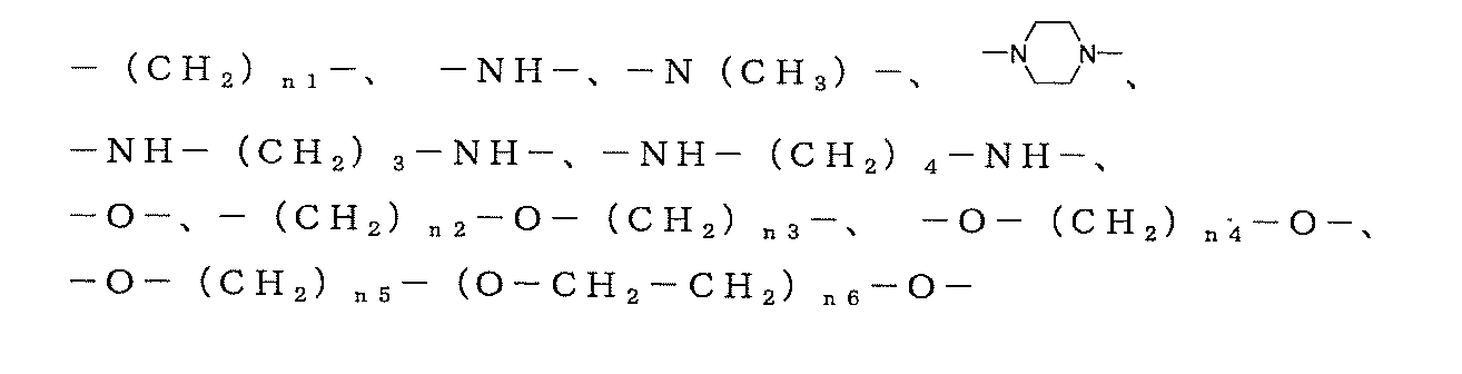
- 請求項1又は2に記載の陰イオン交換膜を製造する方法であって、
(1) ジアリルアンモニウム塩を含むモノマー成分及び架橋剤を含んでなるモノマー組成物を、水に対して不溶な樹脂からなる微多孔フィルムの空隙内に導入する工程と、
(2) 前記微多孔フィルムの空隙部に導入された前記モノマー組成物を重合及び架橋させる工程と、
を含む陰イオン交換膜の製造方法。 - 前記工程(1)における前記微多孔フィルムの空隙内への前記モノマー組成物の導入が、(1a)前記微多孔フィルムに対して浸透性を有し、且つ水混和性を有する有機溶媒からなる導入促進剤、又は該導入促進剤以外の極性有機溶媒或いは水と、該導入促進剤と、の混合溶媒に前記モノマー成分及び架橋剤を溶解させた溶液からなり、前記微多孔フィルムに対して浸透性を有する第一の原料溶液を準備し、前記微多孔フィルムと、当該第一の原料溶液と、を接触させる工程を含む導入方法により行われる請求項3に記載の方法。
- 前記導入方法が、(1b)前記導入促進剤と、前記モノマー成分及び架橋剤の溶液と、の混合溶液からなり、該混合溶液における前記導入促進剤の濃度は前記第一の原料溶液における導入促進剤の濃度よりも低く、且つ前記モノマー成分の濃度は前記第一の原料溶液における前記モノマー濃度より高い第二の原料溶液を準備し、工程(1a)において前記第一の原料溶液と接触させた前記微多孔フィルムと前記第二の原料溶液とを接触させる工程を更に含む請求項4に記載の方法。
- 前記導入方法が、(1b’)前記導入促進剤と、前記モノマー成分及び架橋剤の溶液と、の混合溶液からなる複数の原料溶液であって、これら原料溶液における前記導入促進剤の濃度は何れも前記第一の原料溶液における導入促進剤の濃度よりも順次低くなると共にこれら原料溶液における前記モノマー成分の濃度は何れも前記第一の原料溶液におけるモノマー成分の濃度よりも順次高くなる複数の原料溶液を準備し、工程(1a)において前記第一の原料溶液と接触させた前記微多孔フィルムと前記各原料溶液とを、原料溶液における前記導入促進剤の濃度が高い順に、順次接触させる工程を更に含む請求項4に記載の方法。
- 前記導入促進剤は、誘電率15以上の水溶性有機溶媒である請求項4~6のいずれかに記載の方法。
- 前記第一の原料溶液における導入促進剤の量が、前記モノマー成分及び架橋剤の合計100質量部に対して1~200質量部である請求項4~7のいずれかに記載の方法。
- 請求項1又は2に記載の陰イオン交換膜からなる固体高分子型燃料電池用隔膜。
- 請求項9に記載の固体高分子型燃料電池用隔膜の両面にガス拡散電極が接合されてなる固体高分子型燃料電池用イオン交換膜/ガス拡散電極接合体。
- 請求項請10に記載の固体高分子型燃料電池用イオン交換膜/ガス拡散電極接合体が装着されてなる固体高分子型燃料電池。
Priority Applications (3)
| Application Number | Priority Date | Filing Date | Title |
|---|---|---|---|
| US13/129,259 US20110281197A1 (en) | 2008-11-14 | 2009-11-12 | Anion-exchange membrane and method for producing the same |
| JP2010537803A JPWO2010055889A1 (ja) | 2008-11-14 | 2009-11-12 | 陰イオン交換膜及びその製造方法 |
| EP09826136A EP2351785A1 (en) | 2008-11-14 | 2009-11-12 | Anion-exchange membrane and method for producing same |
Applications Claiming Priority (2)
| Application Number | Priority Date | Filing Date | Title |
|---|---|---|---|
| JP2008-292344 | 2008-11-14 | ||
| JP2008292344 | 2008-11-14 |
Publications (1)
| Publication Number | Publication Date |
|---|---|
| WO2010055889A1 true WO2010055889A1 (ja) | 2010-05-20 |
Family
ID=42170020
Family Applications (1)
| Application Number | Title | Priority Date | Filing Date |
|---|---|---|---|
| PCT/JP2009/069290 Ceased WO2010055889A1 (ja) | 2008-11-14 | 2009-11-12 | 陰イオン交換膜及びその製造方法 |
Country Status (6)
| Country | Link |
|---|---|
| US (1) | US20110281197A1 (ja) |
| EP (1) | EP2351785A1 (ja) |
| JP (1) | JPWO2010055889A1 (ja) |
| KR (1) | KR20110101131A (ja) |
| TW (1) | TW201030066A (ja) |
| WO (1) | WO2010055889A1 (ja) |
Cited By (17)
| Publication number | Priority date | Publication date | Assignee | Title |
|---|---|---|---|---|
| WO2011087459A1 (en) * | 2010-01-14 | 2011-07-21 | Agency For Science, Technology And Research | Method of forming a polymer electrolyte membrane |
| JP2012049111A (ja) * | 2010-07-30 | 2012-03-08 | Toyota Central R&D Labs Inc | 電解質、並びに、燃料電池、Li二次電池、二次電池及び一次電池 |
| JP2012201772A (ja) * | 2011-03-25 | 2012-10-22 | Tokuyama Corp | 陰イオン伝導性樹脂及びその製造方法 |
| CN103755988A (zh) * | 2013-12-31 | 2014-04-30 | 山东天维膜技术有限公司 | 一种基于烯丙基单体制备阴离子交换膜的方法 |
| JP2014107169A (ja) * | 2012-11-28 | 2014-06-09 | Daihatsu Motor Co Ltd | 膜電極接合体の製造方法 |
| JP2015083683A (ja) * | 2014-11-18 | 2015-04-30 | 株式会社トクヤマ | 陰イオン伝導性樹脂 |
| WO2015190075A1 (ja) * | 2014-06-13 | 2015-12-17 | 日東電工株式会社 | アニオン交換形電解質膜、それを備えた燃料電池用の膜-電極接合体及び燃料電池 |
| JP2016536133A (ja) * | 2013-09-17 | 2016-11-24 | ゼネラル・エレクトリック・カンパニイ | イオン交換ポリマー及びイオン交換ポリマーの製造方法 |
| WO2017098732A1 (ja) | 2015-12-11 | 2017-06-15 | 日東電工株式会社 | 電解質膜及びその製造方法、並びに電解質膜を備えた燃料電池用の膜-電極接合体 |
| KR20170122675A (ko) * | 2016-04-27 | 2017-11-06 | 라이브니츠-인스티튜트 퓌어 폴리머포르슝 드레스덴 에.파우. | 비수용성 음이온 교환 재료 |
| JP2018108583A (ja) * | 2018-02-09 | 2018-07-12 | ゼネラル・エレクトリック・カンパニイ | イオン交換ポリマー及びイオン交換ポリマーの製造方法 |
| JP2019518809A (ja) * | 2016-03-28 | 2019-07-04 | ユニバーシティー オブ デラウェア | ヒドロキシド交換膜およびヒドロキシド交換アイオノマーとしての使用のためのポリ(アリールピペリジニウム)ポリマー |
| JP2020536165A (ja) * | 2017-09-28 | 2020-12-10 | ヤン,ユシャン | アニオン交換膜およびアイオノマーとして使用するための安定なカチオン性ペンダント基を有するものを含むポリ(アリールピペリジニウム)ポリマー |
| JP2022544965A (ja) * | 2019-08-16 | 2022-10-24 | トーレ・アドバンスド・マテリアルズ・コリア・インコーポレーテッド | 一価陰イオン選択性イオン交換膜 |
| JP2022553774A (ja) * | 2019-10-28 | 2022-12-26 | サントル ナシオナル ドゥ ラ ルシェルシェ サイアンティフィク | アニオン性高分子電解質 |
| US11827743B2 (en) | 2019-03-28 | 2023-11-28 | University Of Delaware | Polymers having stable cationic pendant groups for use as anion exchange membranes |
| EP4376133A1 (en) * | 2022-11-24 | 2024-05-29 | Korea Institute of Science and Technology | Ionomer comprising compound derived from n,n-diallylamine and manufacturing method thereof |
Families Citing this family (24)
| Publication number | Priority date | Publication date | Assignee | Title |
|---|---|---|---|---|
| SG169305A1 (en) * | 2009-08-26 | 2011-03-30 | Siemens Pte Ltd | Ion exchange membranes |
| JP5889907B2 (ja) | 2010-10-15 | 2016-03-22 | エヴォクア ウォーター テクノロジーズ エルエルシーEvoqua Water Technologiesllc | カチオン交換膜を製造するためのモノマー溶液の製造方法 |
| CN103237600B (zh) | 2010-10-15 | 2016-07-13 | 伊沃夸水处理技术有限责任公司 | 阴离子交换膜及制造方法 |
| US9199203B2 (en) * | 2012-04-19 | 2015-12-01 | Saltworks Technologies, Inc. | Resilient ion exchange membranes prepared by polymerizing ionic surfactant monomers |
| KR20130132107A (ko) | 2012-05-25 | 2013-12-04 | 삼성전자주식회사 | 이온 교환막 충전용 조성물, 이온 교환막의 제조방법, 이온 교환막 및 레독스 플로우 전지 |
| US20140087275A1 (en) * | 2012-09-21 | 2014-03-27 | Jose Viriato Coelho Vargas | Alkaline Membrane Fuel Cell |
| WO2014055123A1 (en) | 2012-10-04 | 2014-04-10 | Evoqua Water Technologies Llc | High-performance anion exchange membranes and methods of making same |
| CA2887132C (en) | 2012-10-11 | 2020-07-21 | Evoqua Water Technologies Llc | Coated ion exchange membranes |
| CA2858238C (en) * | 2012-10-19 | 2015-04-21 | Saltworks Technologies Inc. | Acrylamide-based crosslinking monomers, their preparation, and uses thereof |
| KR102020485B1 (ko) | 2013-01-11 | 2019-09-11 | 삼성디스플레이 주식회사 | 블록 공중합체, 그 형성 방법 및 패턴 형성 방법 |
| US9061254B2 (en) | 2013-01-14 | 2015-06-23 | Kraton Polymers U.S. Llc | Block copolymers, their manufacture and their use |
| BR122015019867A2 (pt) | 2013-01-14 | 2019-08-27 | Kraton Polymers Us Llc | processo para preparar um copolímero de bloco funcionalizado em amino |
| US8895633B2 (en) | 2013-03-04 | 2014-11-25 | King Fahd University Of Petroleum And Minerals | Cross-linked polyaminocarboxylates for the removal of metal ions from aqueous solutions |
| US9051197B2 (en) * | 2013-09-09 | 2015-06-09 | King Fahd University Of Petroleum And Minerals | Cross-linked polyaminomethyldiphosphonate for the removal of metal ions from wastewater |
| KR102126034B1 (ko) | 2013-11-01 | 2020-06-23 | 삼성전자주식회사 | 이온 교환막, 그 제조방법 및 그것을 포함한 레독스 플로우 전지 |
| EP2991153B1 (en) * | 2014-08-28 | 2023-08-23 | Samsung Electronics Co., Ltd. | Composite electrolyte and lithium battery including the same |
| WO2016147640A1 (ja) * | 2015-03-13 | 2016-09-22 | 日東電工株式会社 | アニオン交換基を有する樹脂、それを用いた樹脂含有液、積層体、部材、電気化学素子及び電気化学デバイス |
| US20170114157A1 (en) | 2015-10-21 | 2017-04-27 | Saudi Arabian Oil Company | Cationic polymers and porous materials |
| GB201702096D0 (en) | 2017-02-08 | 2017-03-22 | Sumitomo Chemical Co | Method |
| JP7404349B2 (ja) | 2018-09-25 | 2023-12-25 | エヴォクア ウォーター テクノロジーズ エルエルシー | 一価選択性カチオン交換膜 |
| CN113471498B (zh) * | 2021-07-07 | 2022-09-23 | 长春工业大学 | 一种多季铵侧长链型聚砜阴离子交换膜及其制备方法 |
| KR102761467B1 (ko) * | 2021-12-23 | 2025-02-06 | 한국에너지기술연구원 | 수산화 이온 전도도가 향상된 세공충진형 음이온 교환 복합막용 전해질 전구체 조성물 및 이를 포함하는 음이온 교환 복합막 |
| EP4306556A1 (en) * | 2022-07-12 | 2024-01-17 | Toyota Jidosha Kabushiki Kaisha | Protic ionic liquid based on diallyl ammonium cation and related membrane |
| US12202788B2 (en) | 2022-09-15 | 2025-01-21 | Xerox Corporation | Gradient membranes formed from free standing structured organic films and methods thereof |
Citations (12)
| Publication number | Priority date | Publication date | Assignee | Title |
|---|---|---|---|---|
| JPH09216964A (ja) | 1996-02-09 | 1997-08-19 | Nitto Denko Corp | 多孔質フィルムおよびそれを用いた電池用セパレータ並びに電池 |
| JPH11135137A (ja) | 1997-10-31 | 1999-05-21 | Asahi Glass Co Ltd | 固体高分子電解質型メタノール燃料電池 |
| JPH11273695A (ja) | 1998-03-19 | 1999-10-08 | Asahi Glass Co Ltd | 固体高分子電解質型メタノール燃料電池 |
| JP2000331693A (ja) | 1999-05-19 | 2000-11-30 | Asahi Glass Co Ltd | 固体高分子型燃料電池 |
| JP2001302729A (ja) | 2000-04-24 | 2001-10-31 | Nippon Shokubai Co Ltd | 高分子架橋体、その製造方法および使用方法 |
| JP2002212222A (ja) * | 2001-01-17 | 2002-07-31 | Nippon Shokubai Co Ltd | 強塩基性樹脂架橋体 |
| JP2002338721A (ja) | 2001-05-16 | 2002-11-27 | Asahi Kasei Corp | ポリオレフィン樹脂多孔質フィルム |
| JP2002367626A (ja) | 2001-06-12 | 2002-12-20 | Tokuyama Corp | ガス拡散電極用イオン伝導性付与剤 |
| JP2003086193A (ja) | 2001-09-13 | 2003-03-20 | Tokuyama Corp | ガス拡散電極の製造方法 |
| WO2005098875A1 (ja) * | 2004-04-08 | 2005-10-20 | Toagosei Co., Ltd. | 電解質膜および膜電極接合体の製造方法並びに燃料電池 |
| JP2007167839A (ja) * | 2005-11-25 | 2007-07-05 | Kureha Corp | 親水性中空糸膜とその製造方法 |
| JP2009143975A (ja) | 2007-12-11 | 2009-07-02 | Nippon Shokubai Co Ltd | 固体電解質用材料 |
Family Cites Families (2)
| Publication number | Priority date | Publication date | Assignee | Title |
|---|---|---|---|---|
| GB2374072B (en) * | 2000-06-16 | 2004-09-22 | Nippon Catalytic Chem Ind | Crosslinked polymer method for manufacturing it and use thereof |
| US20040137297A1 (en) * | 2002-12-26 | 2004-07-15 | Hitoshi Matsuoka | Ion exchange membrane and production process therefor |
-
2009
- 2009-11-12 KR KR1020117010765A patent/KR20110101131A/ko not_active Withdrawn
- 2009-11-12 EP EP09826136A patent/EP2351785A1/en not_active Withdrawn
- 2009-11-12 WO PCT/JP2009/069290 patent/WO2010055889A1/ja not_active Ceased
- 2009-11-12 US US13/129,259 patent/US20110281197A1/en not_active Abandoned
- 2009-11-12 JP JP2010537803A patent/JPWO2010055889A1/ja not_active Withdrawn
- 2009-11-13 TW TW098138593A patent/TW201030066A/zh unknown
Patent Citations (12)
| Publication number | Priority date | Publication date | Assignee | Title |
|---|---|---|---|---|
| JPH09216964A (ja) | 1996-02-09 | 1997-08-19 | Nitto Denko Corp | 多孔質フィルムおよびそれを用いた電池用セパレータ並びに電池 |
| JPH11135137A (ja) | 1997-10-31 | 1999-05-21 | Asahi Glass Co Ltd | 固体高分子電解質型メタノール燃料電池 |
| JPH11273695A (ja) | 1998-03-19 | 1999-10-08 | Asahi Glass Co Ltd | 固体高分子電解質型メタノール燃料電池 |
| JP2000331693A (ja) | 1999-05-19 | 2000-11-30 | Asahi Glass Co Ltd | 固体高分子型燃料電池 |
| JP2001302729A (ja) | 2000-04-24 | 2001-10-31 | Nippon Shokubai Co Ltd | 高分子架橋体、その製造方法および使用方法 |
| JP2002212222A (ja) * | 2001-01-17 | 2002-07-31 | Nippon Shokubai Co Ltd | 強塩基性樹脂架橋体 |
| JP2002338721A (ja) | 2001-05-16 | 2002-11-27 | Asahi Kasei Corp | ポリオレフィン樹脂多孔質フィルム |
| JP2002367626A (ja) | 2001-06-12 | 2002-12-20 | Tokuyama Corp | ガス拡散電極用イオン伝導性付与剤 |
| JP2003086193A (ja) | 2001-09-13 | 2003-03-20 | Tokuyama Corp | ガス拡散電極の製造方法 |
| WO2005098875A1 (ja) * | 2004-04-08 | 2005-10-20 | Toagosei Co., Ltd. | 電解質膜および膜電極接合体の製造方法並びに燃料電池 |
| JP2007167839A (ja) * | 2005-11-25 | 2007-07-05 | Kureha Corp | 親水性中空糸膜とその製造方法 |
| JP2009143975A (ja) | 2007-12-11 | 2009-07-02 | Nippon Shokubai Co Ltd | 固体電解質用材料 |
Non-Patent Citations (1)
| Title |
|---|
| HAYASHI ET AL., TETRAHEDRON, vol. 48, no. 11, 1992, pages 1999 |
Cited By (31)
| Publication number | Priority date | Publication date | Assignee | Title |
|---|---|---|---|---|
| WO2011087459A1 (en) * | 2010-01-14 | 2011-07-21 | Agency For Science, Technology And Research | Method of forming a polymer electrolyte membrane |
| JP2012049111A (ja) * | 2010-07-30 | 2012-03-08 | Toyota Central R&D Labs Inc | 電解質、並びに、燃料電池、Li二次電池、二次電池及び一次電池 |
| US8815469B2 (en) | 2010-07-30 | 2014-08-26 | Kabushiki Kaisha Toyota Chuo Kenkyusho | Electrolyte, and fuel cell, Li secondary battery, secondary battery and primary battery using the electrolyte |
| JP2012201772A (ja) * | 2011-03-25 | 2012-10-22 | Tokuyama Corp | 陰イオン伝導性樹脂及びその製造方法 |
| JP2014107169A (ja) * | 2012-11-28 | 2014-06-09 | Daihatsu Motor Co Ltd | 膜電極接合体の製造方法 |
| JP2016536133A (ja) * | 2013-09-17 | 2016-11-24 | ゼネラル・エレクトリック・カンパニイ | イオン交換ポリマー及びイオン交換ポリマーの製造方法 |
| CN103755988A (zh) * | 2013-12-31 | 2014-04-30 | 山东天维膜技术有限公司 | 一种基于烯丙基单体制备阴离子交换膜的方法 |
| WO2015190075A1 (ja) * | 2014-06-13 | 2015-12-17 | 日東電工株式会社 | アニオン交換形電解質膜、それを備えた燃料電池用の膜-電極接合体及び燃料電池 |
| WO2015190074A1 (ja) * | 2014-06-13 | 2015-12-17 | 日東電工株式会社 | アニオン交換形電解質膜の製造方法及びその方法により得られたアニオン交換形電解質膜、それを備えた燃料電池用の膜-電極接合体及び燃料電池 |
| JP6064087B2 (ja) * | 2014-06-13 | 2017-01-18 | 日東電工株式会社 | アニオン交換形電解質膜、それを備えた燃料電池用の膜−電極接合体及び燃料電池 |
| US9692072B2 (en) | 2014-06-13 | 2017-06-27 | Nitto Denko Corporation | Anion exchange electrolyte membrane, membrane-electrode assembly for fuel cell including the same, and fuel cell including the same |
| JP2015083683A (ja) * | 2014-11-18 | 2015-04-30 | 株式会社トクヤマ | 陰イオン伝導性樹脂 |
| WO2017098732A1 (ja) | 2015-12-11 | 2017-06-15 | 日東電工株式会社 | 電解質膜及びその製造方法、並びに電解質膜を備えた燃料電池用の膜-電極接合体 |
| KR20180090356A (ko) | 2015-12-11 | 2018-08-10 | 닛토덴코 가부시키가이샤 | 전해질막 및 그의 제조 방법, 그리고 전해질막을 구비한 연료 전지용의 막-전극 접합체 |
| US10637087B2 (en) | 2015-12-11 | 2020-04-28 | Nitto Denko Corporation | Electrolyte membrane, method for producing the same, and membrane-electrode assembly for fuel cells that includes electrolyte membrane |
| JP7153561B2 (ja) | 2016-03-28 | 2022-10-14 | ユニバーシティー オブ デラウェア | ヒドロキシド交換膜およびヒドロキシド交換アイオノマーとしての使用のためのポリ(アリールピペリジニウム)ポリマー |
| JP2019518809A (ja) * | 2016-03-28 | 2019-07-04 | ユニバーシティー オブ デラウェア | ヒドロキシド交換膜およびヒドロキシド交換アイオノマーとしての使用のためのポリ(アリールピペリジニウム)ポリマー |
| JP7242160B2 (ja) | 2016-04-27 | 2023-03-20 | ライプニッツ-インスティチュート フュア ポリマーフォルシュング ドレスデン エーファウ | 水溶性アニオン交換体材料 |
| JP2017222839A (ja) * | 2016-04-27 | 2017-12-21 | ライプニッツ−インスティチュート フュア ポリマーフォルシュング ドレスデン エーファウLeibniz−Institut fuer Polymerforschung Dresden e.V. | 水溶性アニオン交換体材料 |
| KR20170122675A (ko) * | 2016-04-27 | 2017-11-06 | 라이브니츠-인스티튜트 퓌어 폴리머포르슝 드레스덴 에.파우. | 비수용성 음이온 교환 재료 |
| KR102035116B1 (ko) | 2016-04-27 | 2019-10-22 | 라이브니츠-인스티튜트 퓌어 폴리머포르슝 드레스덴 에.파우. | 비수용성 음이온 교환 재료 |
| JP2020536165A (ja) * | 2017-09-28 | 2020-12-10 | ヤン,ユシャン | アニオン交換膜およびアイオノマーとして使用するための安定なカチオン性ペンダント基を有するものを含むポリ(アリールピペリジニウム)ポリマー |
| JP7532253B2 (ja) | 2017-09-28 | 2024-08-13 | ユニバーシティー オブ デラウェア | アニオン交換膜およびアイオノマーとして使用するための安定なカチオン性ペンダント基を有するものを含むポリ(アリールピペリジニウム)ポリマー |
| US11512156B2 (en) | 2017-09-28 | 2022-11-29 | University Of Delaware | Poly(aryl piperidinium) polymers including those with stable cationic pendant groups for use as anion exchange membranes and ionomers |
| JP2018108583A (ja) * | 2018-02-09 | 2018-07-12 | ゼネラル・エレクトリック・カンパニイ | イオン交換ポリマー及びイオン交換ポリマーの製造方法 |
| US11827743B2 (en) | 2019-03-28 | 2023-11-28 | University Of Delaware | Polymers having stable cationic pendant groups for use as anion exchange membranes |
| JP7439237B2 (ja) | 2019-08-16 | 2024-02-27 | トーレ・アドバンスド・マテリアルズ・コリア・インコーポレーテッド | 一価陰イオン選択性イオン交換膜 |
| JP2022544965A (ja) * | 2019-08-16 | 2022-10-24 | トーレ・アドバンスド・マテリアルズ・コリア・インコーポレーテッド | 一価陰イオン選択性イオン交換膜 |
| JP2022553774A (ja) * | 2019-10-28 | 2022-12-26 | サントル ナシオナル ドゥ ラ ルシェルシェ サイアンティフィク | アニオン性高分子電解質 |
| JP7657791B2 (ja) | 2019-10-28 | 2025-04-07 | サントル ナシオナル ドゥ ラ ルシェルシェ サイアンティフィク | アニオン性高分子電解質 |
| EP4376133A1 (en) * | 2022-11-24 | 2024-05-29 | Korea Institute of Science and Technology | Ionomer comprising compound derived from n,n-diallylamine and manufacturing method thereof |
Also Published As
| Publication number | Publication date |
|---|---|
| KR20110101131A (ko) | 2011-09-15 |
| EP2351785A1 (en) | 2011-08-03 |
| TW201030066A (en) | 2010-08-16 |
| JPWO2010055889A1 (ja) | 2012-04-12 |
| US20110281197A1 (en) | 2011-11-17 |
Similar Documents
| Publication | Publication Date | Title |
|---|---|---|
| WO2010055889A1 (ja) | 陰イオン交換膜及びその製造方法 | |
| TWI484692B (zh) | A battery for fuel cell and a method for manufacturing the same | |
| CN104011921B (zh) | 氧化还原液流二次电池和氧化还原液流二次电池用电解质膜 | |
| JP5386371B2 (ja) | 直接液体燃料型燃料電池用隔膜およびその製造方法 | |
| JP5566021B2 (ja) | アニオン型燃料電池用隔膜およびその製造方法 | |
| JP5404419B2 (ja) | 固体高分子電解質型燃料電池隔膜 | |
| JP5770163B2 (ja) | 固体高分子型燃料電池用隔膜の製造方法 | |
| US8231997B2 (en) | Electrolyte membrane-electrode membrane assembly for solid polymer fuel cell and production method thereof, and fuel cell equipped therewith | |
| KR20070057171A (ko) | 연료 전지용 격막 및 그의 제조 방법 | |
| TW201716232A (zh) | 陰離子交換體、離子傳導性賦予劑、觸媒電極層、膜-電極接合體、陰離子交換膜型燃料電池及陰離子交換膜型水電解裝置 | |
| JP2009140783A (ja) | ガス拡散電極用水酸化物イオン伝導性付与剤 | |
| WO2009096473A1 (ja) | 燃料電池用隔膜およびその製造方法 | |
| TW200525805A (en) | Membrane electrode assembly, manufacturing process therefor and direct type fuel cell therewith | |
| JP4849893B2 (ja) | 陰イオン交換樹脂膜形成用4級化剤、ガス拡散電極膜、固体電解質膜及びそれを具備する固体高分子型燃料電池 | |
| JP5164149B2 (ja) | 陽イオン交換膜およびその製造方法 | |
| JP2015165461A (ja) | 複合電解質膜及びその製造方法 | |
| JP5551877B2 (ja) | 燃料電池用隔膜およびその製造方法 | |
| JP2016207609A (ja) | 複合高分子電解質膜およびその製造方法ならびに膜電極接合体、燃料電池 | |
| JP2016207610A (ja) | 複合高分子電解質膜およびその製造方法ならびに膜電極接合体、燃料電池 | |
| JP2009093998A (ja) | 直接液体燃料型燃料電池用隔膜およびその製造方法 | |
| JP5111349B2 (ja) | 改質炭化水素系陽イオン交換膜およびその製造方法 | |
| JP5317416B2 (ja) | 電解質膜−触媒電極接合体および直接液体型燃料電池 | |
| JP2006172858A (ja) | 電極に対する接着性に優れた電解質膜 |
Legal Events
| Date | Code | Title | Description |
|---|---|---|---|
| 121 | Ep: the epo has been informed by wipo that ep was designated in this application |
Ref document number: 09826136 Country of ref document: EP Kind code of ref document: A1 |
|
| ENP | Entry into the national phase |
Ref document number: 2010537803 Country of ref document: JP Kind code of ref document: A Ref document number: 20117010765 Country of ref document: KR Kind code of ref document: A |
|
| NENP | Non-entry into the national phase |
Ref country code: DE |
|
| WWE | Wipo information: entry into national phase |
Ref document number: 2009826136 Country of ref document: EP |
|
| WWE | Wipo information: entry into national phase |
Ref document number: 13129259 Country of ref document: US |