WO2010058609A1 - 電動機の回転子及び電動機及び送風機及び圧縮機 - Google Patents
電動機の回転子及び電動機及び送風機及び圧縮機 Download PDFInfo
- Publication number
- WO2010058609A1 WO2010058609A1 PCT/JP2009/051639 JP2009051639W WO2010058609A1 WO 2010058609 A1 WO2010058609 A1 WO 2010058609A1 JP 2009051639 W JP2009051639 W JP 2009051639W WO 2010058609 A1 WO2010058609 A1 WO 2010058609A1
- Authority
- WO
- WIPO (PCT)
- Prior art keywords
- permanent magnet
- rotor
- magnet
- insertion hole
- electric motor
- Prior art date
- Legal status (The legal status is an assumption and is not a legal conclusion. Google has not performed a legal analysis and makes no representation as to the accuracy of the status listed.)
- Ceased
Links
Images








Classifications
-
- H—ELECTRICITY
- H02—GENERATION; CONVERSION OR DISTRIBUTION OF ELECTRIC POWER
- H02K—DYNAMO-ELECTRIC MACHINES
- H02K1/00—Details of the magnetic circuit
- H02K1/06—Details of the magnetic circuit characterised by the shape, form or construction
- H02K1/22—Rotating parts of the magnetic circuit
- H02K1/27—Rotor cores with permanent magnets
- H02K1/2706—Inner rotors
- H02K1/272—Inner rotors the magnetisation axis of the magnets being perpendicular to the rotor axis
- H02K1/274—Inner rotors the magnetisation axis of the magnets being perpendicular to the rotor axis the rotor consisting of two or more circumferentially positioned magnets
- H02K1/2753—Inner rotors the magnetisation axis of the magnets being perpendicular to the rotor axis the rotor consisting of two or more circumferentially positioned magnets the rotor consisting of magnets or groups of magnets arranged with alternating polarity
- H02K1/276—Magnets embedded in the magnetic core, e.g. interior permanent magnets [IPM]
- H02K1/2766—Magnets embedded in the magnetic core, e.g. interior permanent magnets [IPM] having a flux concentration effect
-
- H—ELECTRICITY
- H02—GENERATION; CONVERSION OR DISTRIBUTION OF ELECTRIC POWER
- H02K—DYNAMO-ELECTRIC MACHINES
- H02K1/00—Details of the magnetic circuit
- H02K1/06—Details of the magnetic circuit characterised by the shape, form or construction
- H02K1/22—Rotating parts of the magnetic circuit
- H02K1/27—Rotor cores with permanent magnets
- H02K1/2706—Inner rotors
- H02K1/272—Inner rotors the magnetisation axis of the magnets being perpendicular to the rotor axis
- H02K1/274—Inner rotors the magnetisation axis of the magnets being perpendicular to the rotor axis the rotor consisting of two or more circumferentially positioned magnets
- H02K1/2753—Inner rotors the magnetisation axis of the magnets being perpendicular to the rotor axis the rotor consisting of two or more circumferentially positioned magnets the rotor consisting of magnets or groups of magnets arranged with alternating polarity
- H02K1/276—Magnets embedded in the magnetic core, e.g. interior permanent magnets [IPM]
Definitions
- the present invention relates to a rotor of a permanent magnet embedded type electric motor. Specifically, it relates to the shape of the permanent magnet.
- the present invention also relates to an electric motor, a blower, and a compressor that use the rotor of the electric motor.
- An embedded magnet motor having a rotor core having a plurality of housing holes formed in the circumferential direction and having a rotor in which magnets are disposed in the housing holes so that the number of magnetic poles is P. Is formed with P / 2 radial receiving holes extending in the substantially radial direction and substantially V-shaped receiving holes protruding outward in the radial direction, and these are alternately formed in the circumferential direction.
- the magnets are arranged in the radial accommodation holes and are arranged in the respective magnet accommodation portions corresponding to the respective straight lines forming the V-shape of the V-shaped accommodation holes.
- Magnet arranged and magnet adjacent to one of its circumferential direction A magnet arranged in the container constitutes one magnetic pole, a magnet arranged in the radial accommodation hole, and a magnet arranged in the magnet accommodation unit adjacent to the other in the circumferential direction,
- An interior magnet type motor in which one different magnetic pole is configured has been proposed (for example, see Patent Document 1). JP 2007-151372 A
- the accommodation hole in which the magnet is disposed has a radial accommodation hole extending in a substantially radial direction and a radially outer side.
- the P-shaped V-shaped receiving holes which are substantially V-shaped, are formed in a P / 2 shape, and are alternately formed in the circumferential direction.
- the magnet is disposed in the radial receiving hole.
- it since it is configured to be disposed in each magnet housing portion corresponding to each straight line forming the V-shape of the V-shaped housing hole, there is a problem that the number of parts is large and productivity is deteriorated.
- the present invention has been made to solve the above-described problems, and an object of the present invention is to provide an electric motor rotor, an electric motor, a blower, and a compressor capable of efficiently arranging permanent magnets.
- the rotor of the electric motor according to the present invention includes a rotor core configured by laminating a predetermined number of electromagnetic steel sheets punched into a predetermined shape, and A plurality of magnet insertion holes provided in the rotor core; A plate-like permanent magnet that is inserted into the magnet insertion hole and whose cross section is composed of a long side and a short side; A chamfered portion is formed at least in the vicinity of the outer peripheral edge portion of the rotor core among the intersection points of the long side and the short side of the permanent magnet.
- the rotor of the electric motor according to the present invention uses one permanent magnet for one magnetic pole.
- the rotor of the electric motor includes a rotor core configured by laminating a predetermined number of electromagnetic steel sheets punched into a predetermined shape, A plurality of V-shaped magnet insertion holes provided in the rotor core; A plate-like permanent magnet that is inserted into the magnet insertion hole and whose cross section is composed of a long side and a short side; A chamfered portion is formed at least in the vicinity of the outer peripheral edge portion of the rotor core among the intersection points of the long side and the short side of the permanent magnet.
- the rotor of the electric motor according to the present invention uses two permanent magnets for one magnetic pole.
- the rotor of the electric motor according to the present invention is such that the permanent magnet is inserted into the magnet insertion hole so that a gap is formed at the outer peripheral edge side end of the permanent magnet rotor core of the magnet insertion hole. It is.
- the gap is formed in the vicinity of the chamfered portion in the vicinity of the outer peripheral edge portion of the rotor core.
- a thin portion having a predetermined radial dimension is formed between the rotor core and the gap.
- the rotor of the electric motor according to the present invention is a permanent magnet other than the gap of the magnet insertion hole when the chamfered portion is formed at the intersection of the long side and the short side of the permanent magnet in the vicinity of the outer peripheral edge of the rotor core.
- the portion facing the chamfered portion of the magnet is shaped to match the chamfered portion.
- one V-shaped magnet insertion hole is divided at the center portion, and a connecting portion is formed between the divided magnet insertion holes.
- the permanent magnet is composed of a rare earth magnet.
- the electric motor according to the present invention includes the rotor of the electric motor.
- a blower according to the present invention includes the above-described electric motor.
- a compressor according to the present invention includes the above-described electric motor.
- the rotor of the electric motor according to the present invention has a chamfered portion formed at least at the intersection of the permanent magnet near the outer peripheral edge of the intersection between the long side and the short side of the permanent magnet.
- a permanent magnet can be inserted efficiently and the magnetic force of the rotor can be improved.
- Embodiment 1 FIG. Before describing the present embodiment, a rotor 100 of a general permanent magnet embedded motor will be described.
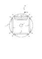
- FIG. 1 to 4 are views showing a rotor 100 of a general permanent magnet embedded electric motor.
- FIG. 1 is a cross-sectional view of the rotor 100 and
- FIG. 2 is a partial cross-sectional view of the rotor core 1 (rotor).
- FIG. 3 is a partial cross-sectional view of the rotor 100, and
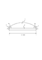
- FIG. 4 is a partial cross-sectional view of the rotor 100 having the maximum circumferential length of the permanent magnet 4. .
- the rotor 100 includes a rotor core 1 having a cylindrical shape and a shaft hole 5 in the center, a flat permanent magnet 4, an end plate for retaining the permanent magnet 4 (not shown), and the like. End plates are arranged at both axial ends of the rotor core 1 in which the permanent magnets 4 are inserted, and the whole is fixed by, for example, rivets.
- the cylindrical rotor core 1 is formed by punching thin electromagnetic steel sheets having a thickness of about 0.2 to 0.5 mm into a predetermined shape one by one and laminating a predetermined number.
- the cylindrical rotor core 1 includes the following elements. (1) Four magnet insertion holes 2 that are arranged at substantially equal intervals in the circumferential direction along the outer peripheral edge of the rotor core 1 and whose cross-sectional shape is substantially rectangular; (2) a circular shaft hole 5 provided in the center of the rotor core 1; (3) Rivet holes, air holes, etc. not shown.
- the magnet insertion hole 2 has both ends in the circumferential direction so that a gap 2 b is formed when the permanent magnet 4 is inserted into the magnet insertion hole 2.
- the shape of the corner is enlarged.
- the air gap 2b is necessary for suppressing magnetic flux leakage at the circumferential end of the permanent magnet 4 itself.
- the thin-walled portion 3 having a substantially constant radial dimension is formed between the end 2a of the outer peripheral side of the magnet insertion hole 2 and the outer peripheral edge of the rotor core 1 at the outer peripheral corners. It is formed over a predetermined length in the circumferential direction (see also FIG. 2).
- the circumferential length of the permanent magnet 4 is L1.
- the magnetization direction of the permanent magnet 4 is a radial direction perpendicular to the circumferential direction of the permanent magnet 4.
- the magnet insertion hole 2 is formed in the circumferential direction along the outer peripheral edge of the rotor core 1.
- L2 be the circumferential length of the portion of the magnet insertion hole 2 where the permanent magnet 4 is inserted.
- the circumferential length L2 of the portion of the magnet insertion hole 2 where the permanent magnet 4 is inserted is slightly longer than the circumferential length L1 of the permanent magnet 4 in order to insert the permanent magnet 4 into the magnet insertion hole 2. Yes.
- FIG. 3 is a partial enlarged view of the state in which the permanent magnet 4 is inserted into the magnet insertion hole 2, and as shown in FIG. 3, the outer peripheral corners of the permanent magnet 4 and the magnet insertion hole 2.
- a space of the gap 2b exists between the end 2a of the portion where the corners at both ends in the circumferential direction are enlarged.
- the length of the single permanent magnet 4 in the circumferential direction should be as large as possible.
- the present embodiment describes a method of extending the circumferential length L1 of the permanent magnet 4 beyond the limit of the rotor 100 of the above-described general permanent magnet embedded motor.
- FIG. 5 to 11 show the first embodiment.
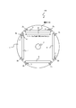
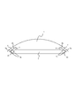
- FIG. 5 is a cross-sectional view of the rotor 100 of the permanent magnet embedded motor
- FIG. 6 is a partial cross-sectional view of the rotor core 1
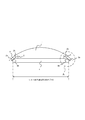
- FIG. 8 is a partial cross-sectional view of the rotor 100
- FIG. 8 is an enlarged view of a portion A of FIG. 7
- FIG. 9 is a cross-sectional view of the rotor 100 of Modification
- FIG. 10 is a partial cross-sectional view of the rotor 100 of Modification 1.
- FIG. 11 is a partial cross-sectional view of the rotor 100 of the second modification.
- the rotor 100 of the permanent magnet embedded motor according to the present embodiment is different from the rotor 100 of the general permanent magnet embedded motor shown in FIG. 1.
- the shape of the permanent magnet 4 is different.
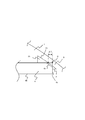
- the permanent magnet 4 of the present embodiment is different from the permanent magnet 4 of the rotor 100 of a general embedded permanent magnet electric motor as follows. (1) The circumferential length L01 of the permanent magnet 4 is longer than the maximum circumferential length L1max (see FIG. 4) of the permanent magnet 4 of the rotor 100 of a general embedded permanent magnet electric motor. (2) The reason why L01> L1max is possible is that the chamfered portion 4a is provided by chamfering the corner portion on the outer peripheral side of the end portion of the permanent magnet 4 in the circumferential direction. In FIG. 5, the chamfered portion 4 a has some reference numerals, and others are omitted.
- the circumferential length L02 of the portion of the magnet insertion hole 2 into which the permanent magnet 4 is inserted is also shown in FIG. 2 is longer than L2 of the general rotor core 1 shown in FIG.
- the circumferential length L01 of the permanent magnet 4 is longer than the maximum circumferential length L1max (see FIG. 4) of the permanent magnet 4 of the rotor 100 of a general embedded permanent magnet electric motor. Will be described with reference to FIG.
- the end of the permanent magnet 4 is ⁇ L on one side relative to the circumferential length L1max of the permanent magnet 4 of FIG. 4 where the end of the permanent magnet 4 contacts the end 2a of the magnet insertion hole 2.
- the circumferential length of the permanent magnet 4 is increased by chamfering the corners on the outer peripheral side of the end portions in the circumferential direction. Since both sides increase by 2 ⁇ L, the relationship between L01 and L1max can be expressed by the following equation (1).
- L01 L1max + 2 ⁇ L (1)
- the circumferential length of the permanent magnet 4 is made larger than that of the permanent magnet 4 having a general shape by chamfering the outer peripheral corner of the circumferential end of the permanent magnet 4 and providing the chamfered portion 4a. can do.
- the magnetic force of the permanent magnet 4 is improved, and the efficiency of the permanent magnet embedded motor can be increased.
- the permanent magnet 4 is shown as being accommodated in the magnet insertion hole 2 without any gap in the circumferential direction and the radial direction in the figure (in FIG. 7, for example), but in reality, between the magnet insertion hole 2 and the permanent magnet 4 In order to allow the permanent magnet 4 to be inserted into the magnet insertion hole 2, there are gaps of a predetermined dimension in the circumferential direction and the radial direction. Therefore, the permanent magnet 4 can be moved by the gap in the magnet insertion hole 2.
- the chamfered shape of the chamfered portion 4 a of the permanent magnet 4 is such that the permanent magnet 4 is thin in the magnet insertion hole 2 at any position within the gap between the magnet insertion hole 2 and the permanent magnet 4. It is preferable to make it the shape which does not contact the part 3 (end part 2a of the magnet insertion hole 2).
- the shape of the chamfered portion 4a of the permanent magnet 4 may be any shape such as a straight line or an arc.
- the permanent magnet 4 is not simply chamfered.
- the circumferential length of the permanent magnet 4 is increased, the permanent magnet 4 and the thin-walled portion 3 of the rotor core 1 are in contact with each other in the shape where the permanent magnet 4 is not chamfered. It is characterized by the shape of the permanent magnet 4 that can be inserted into the hole 2.
- the intersection B on the extended line of the long side 4b and the short side 4c of the permanent magnet 4 shown in FIG. 8 is not in the gap 2b at the end of the permanent magnet 4, and the thin wall of the rotor core 1 is thin.
- the corner portion on the outer peripheral side of the permanent magnet 4 is chamfered to provide a chamfered portion 4 a so that the portion does not come into contact with the thin portion 3 of the rotor core 1. It is characterized by that.
- the demagnetized portion is formed by chamfering the outer peripheral side corner of the permanent magnet 4 and providing the chamfered portion 4 a. Therefore, the demagnetization resistance of the permanent magnet 4 is also improved.
- FIG. 9 is a cross-sectional view of the rotor 100 of the first modification
- FIG. 10 is a partial cross-sectional view of the rotor 100 of the first modification.
- the permanent magnet 4 has a shape in which four corners are chamfered in substantially the same shape and chamfered portions 4 a are provided in the four corners.
- the permanent magnet 4 shown in FIG. 9 and FIG. 10 has a cross-sectional shape that is symmetrical left and right and up and down. Therefore, there is no restriction on the direction in which the permanent magnet 4 is inserted, and productivity is improved.
- the detailed shape of the magnet insertion hole 2 corresponds to the corner portion of the permanent magnet 4, and the magnet insertion hole 2 is provided with a slight depression so that the corner portion of the permanent magnet 4 does not hit. It has a shape like this. By chamfering all the corners, the magnet insertion hole 2 does not need a recess corresponding to the corner of the permanent magnet 4. Thereby, the shape of the mold is simplified and the cost of the mold can be reduced.
- FIG. 11 is a partial cross-sectional view of the rotor 100 of the second modification. As shown in FIG. 11, a portion corresponding to the chamfered portion 4 a inside the permanent magnet 4 of the magnet insertion hole 2 is shaped to match the chamfered portion 4 a of the permanent magnet 4 and is defined as a chamfered portion 2 c.
- the rotor 100 of Modification 1 shown in FIGS. 9 and 10 has a shape in which the four corners of the permanent magnet 4 are chamfered in substantially the same shape, and the chamfered portions 4a are provided in the four corners. There is an air gap 2 d between the magnet insertion hole 2 and the permanent magnet 4.
- the gap 2d is reduced.
- the permeance (reciprocal of the magnetic resistance) of the magnetic path 4 is improved, and the magnetic force and demagnetization resistance of the permanent magnet 4 are improved.
- the shape of the chamfered portion 2c of the magnet insertion hole 2 is preferably formed in accordance with the shape of the chamfered portion 4a at the corner of the permanent magnet 4, but the four corners of the permanent magnet 4 are chamfered in substantially the same shape.
- the gap 2d generated by providing the chamfered portions 4a at the four corners only needs to be made small, and the same effect can be obtained by shapes such as rounding in addition to the straight line.
- the permanent magnet 4 may have a small chamfer, but in the present embodiment, when the permanent magnet 4 and the thin portion 3 of the rotor core 1 are in contact with each other when the permanent magnet 4 is not chamfered, The permanent magnet 4 is chamfered so as not to contact the thin portion 3 of the rotor core 1.
- the present embodiment is different from that in which the permanent magnet 4 and the thin portion 3 of the rotor core 1 are not in contact with each other and the permanent magnet 4 is chamfered.
- Both ends in the circumferential direction of the magnet insertion hole 2 have a shape in which corners on the outer peripheral side of both ends are enlarged so that a gap 2b is formed when the permanent magnet 4 is inserted into the magnet insertion hole 2.
- the shape of the gap 2b is not limited to the shape shown in FIGS. 5 to 11 and may be any shape.
- the shape of the chamfered portion 4a of the permanent magnet 4 may not be a straight line, but may be a round shape (arc) or the like. In short, if the corners of the permanent magnet 4 are formed so as not to come into contact with the thin-walled portion 3 of the rotor core 1, the effect is obtained.
- FIG. 12 to 21 are diagrams showing the second embodiment.
- FIG. 12 is a partial cross-sectional view of the rotor core 1
- FIG. 13 is a partial cross-sectional view of the rotor 100
- FIG. 14 is an enlarged view of a portion D in FIG. 15 is a partial cross-sectional view of the rotor 100 of the first modification
- FIG. 16 is an enlarged view of an E portion of FIG. 15
- FIG. 17 is a partial cross-sectional view of the rotor 100 of the second modification
- FIG. FIG. 19 is a partial cross-sectional view of the rotor core 1 of the fourth modification
- FIG. 20 is a partial cross-sectional view of the rotor 100 of the fourth modification
- the rotor core 1 of the present embodiment includes a V-shaped magnet insertion hole 2.
- the V-shaped magnet insertion hole 2 is convex on the inner side (axial hole 5 side) of the rotor core 1. The only difference is that the magnet insertion hole 2 is V-shaped, unlike the rotor core 1 of the first embodiment shown in FIG.
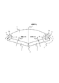
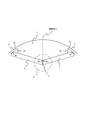
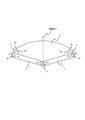
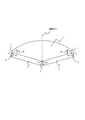
- FIG. 13 shows one magnetic pole of the rotor 100, but two permanent magnets 4 are inserted into the V-shaped magnet insertion hole 2. As shown in the figure, the two permanent magnets 4 are magnetized so that one permanent magnet 4 constitutes one magnetic pole.
- the shape of the two permanent magnets 4 is symmetrical with respect to the magnetic pole center.
- the two permanent magnets 4 are not chamfered at the corners at the end on the magnetic pole center side.
- angular part of the outer peripheral side is chamfered, and the chamfer part 4a is formed.
- the intersection D between the long side 4b and the short side 4c of the permanent magnet 4 is It is not in the gap 2b at the end of the permanent magnet 4, but has a size such that it is positioned on the thin portion 3 of the rotor core 1 or on the outer side in the radial direction.
- the chamfered portion 4a is positioned in the air gap 2b, and the two permanent magnets 4 are replaced with V-shaped magnets.
- the two permanent magnets 4 are configured not to contact the thin portion 3.
- angular part of the outer peripheral side of the edge part of each magnetic pole center side is contacting in the substantially magnetic pole center.
- the corners on the opposite outer peripheral side (shaft hole 5 side) of the end portions on the magnetic pole center side are not in contact with each other.
- intersection D (FIG. 14) between the long side 4 b and the short side 4 c of the permanent magnet 4 is not in the gap 2 b at the end of the permanent magnet 4, but on the thin-walled portion 3 of the rotor core 1 or radially outward from it. If the size is such that it is positioned, the two permanent magnets 4 cannot be inserted into the V-shaped magnet insertion hole 2.
- the chamfered portion 4a enters the gap 2b, and the two permanent magnets 4 are inserted into a V-shaped magnet.
- the two permanent magnets 4 are formed so as not to contact the thin wall portion 3.
- the width can be increased, and the magnetic force of the rotor 100 can be improved. As a result, it is possible to increase the efficiency of the permanent magnet embedded motor.
- the permanent magnet 4 is illustrated as being accommodated in the magnet insertion hole 2 without any gap in the circumferential direction and the radial direction, but in reality, the permanent magnet 4 is permanently disposed between the magnet insertion hole 2 and the permanent magnet 4. In order to allow the magnet 4 to be inserted into the magnet insertion hole 2, there are gaps of predetermined dimensions in the circumferential direction and the radial direction. Therefore, the permanent magnet 4 can be moved by the gap in the magnet insertion hole 2.
- the chamfered shape of the chamfered portion 4 a of the permanent magnet 4 is such that the permanent magnet 4 is thin in the magnet insertion hole 2 at any position within the gap between the magnet insertion hole 2 and the permanent magnet 4. It is preferable to make it the shape which does not contact the part 3 (end part 2a of the magnet insertion hole 2).
- the permanent magnet 4 is not simply chamfered.
- the circumferential length (long side 4b) of the permanent magnet 4 is increased, the permanent magnet 4 and the thin portion 3 of the rotor core 1 are in contact with each other in the shape where the permanent magnet 4 is not chamfered.
- the permanent magnet 4 is chamfered and can be inserted into the magnet insertion hole 2.
- the intersection D on the extended line of the long side 4b and the short side 4c of the permanent magnet 4 shown in FIG. 14 is not in the gap 2b at the end of the permanent magnet 4, and the thin wall of the rotor core 1 is thin.
- the corner portion on the outer peripheral side of the permanent magnet 4 is chamfered to provide a chamfered portion 4 a so that the portion does not come into contact with the thin portion 3 of the rotor core 1. It is characterized by that.
- the demagnetized portion is formed by chamfering the outer peripheral side corner of the permanent magnet 4 and providing the chamfered portion 4 a. Therefore, the demagnetization resistance of the permanent magnet 4 is also improved.
- the two permanent magnets 4 chamfer the corners on the outer peripheral side of the end on the air gap 2b side and the corners on the outer peripheral side of the end on the magnetic pole center side to form a chamfered portion 4a.
- two permanent magnets 4 are in contact with the outer peripheral corners of the respective magnetic pole center side at the substantially magnetic pole center.
- the direction length (long side 4b) cannot be increased.
- the peripheral direction of the permanent magnet 4 is formed by chamfering the corners on the outer peripheral side of the end portions on the magnetic pole center side of the two permanent magnets 4 to form the chamfered portion 4a.
- the length (long side 4b) can be increased.
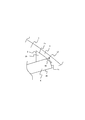
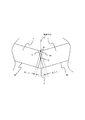
- FIG. 16 shows the circumferential length of the permanent magnet 4 by chamfering the corners on the outer peripheral side of the end portions on the magnetic pole center side of the two permanent magnets 4 to form the chamfered portion 4a. It shows whether the long side 4b) can be lengthened.
- the portion represented by the broken line in FIG. 16 chamfers the corners on the outer peripheral side of the end portions on the magnetic pole center side of the two permanent magnets 4 to form the two permanent magnets 4 before forming the chamfered portion 4a.
- the end of each magnetic pole center side is shown. In this case, the two permanent magnets 4 are in contact at the point F.
- the chamfered portion 4a is formed by chamfering the outer peripheral corners of the end portions of the two permanent magnets 4 on the magnetic pole center side, the point where the two permanent magnets 4 come into contact is the point G. Moving.
- each permanent magnet 4 chamfers the corner
- the circumferential length (long side 4b) is shortened by ⁇ L1.
- the corners on the outer peripheral side of the end portions of the two permanent magnets 4 on the magnetic pole center side are chamfered to form a chamfered portion 4a, so that the axial direction of the permanent magnet 4 is reversed. Therefore, the operation of inserting the permanent magnet 4 into the magnet insertion hole 2 is facilitated, and the productivity is improved.
- the detailed shape of the magnet insertion hole 2 corresponds to the corner portion of the permanent magnet 4, and the magnet insertion hole 2 is provided with a slight depression so that the corner portion of the permanent magnet 4 does not hit. It has a shape like this. By chamfering all the corners of the permanent magnet 4, the magnet insertion hole 2 does not need a recess corresponding to the corner of the permanent magnet 4. Thereby, the shape of the mold is simplified and the cost of the mold can be reduced.
- 17 has a shape in which four corners of the permanent magnet 4 are chamfered in substantially the same shape and chamfered portions 4a are provided in the four corners. 2 and the permanent magnet 4, a gap 2 d exists at the end of the magnet insertion hole 2 on the thin-walled portion 3 side.
- the gap 2 d is formed at the end of the magnet insertion hole 2 on the thin-walled portion 3 side corresponding to the chamfered portion 4 a inside the permanent magnet 4 of the magnet insertion hole 2, and the chamfered portion of the permanent magnet 4.
- the shape is adjusted to 4a, and the chamfer 2c is formed.
- the rotor core 1 shown in FIG. 19 has a V-shaped magnet insertion hole 2 divided into two. A connecting portion 6 exists between the two magnet insertion holes 2.
- the magnetic pole center side ends 2e of the two magnet insertion holes 2 face each other in parallel with the connecting portion 6 therebetween.
- the chamfered portion 2c is connected to the inside of the magnetic pole center side end portion 2e.
- a chamfered portion 2c is connected to the inside of the end portion 2a on the thin portion 3 side.
- the four corner portions are chamfered, and the two permanent magnets 4 having the chamfered portions 4 a are inserted into the two magnet insertion holes 2.
- the connecting portion 6 is provided for the purpose of improving the strength of the rotor 100 against centrifugal force and electromagnetic force, and preventing damage due to the movement of the permanent magnet 4 during operation and contact between the permanent magnets 4.
- FIG. 21 is an enlarged view of the H portion of FIG. 20, but for easy understanding, chamfering that is continuous with the magnetic pole center side end portion 2 e of the two magnet insertion holes 2 facing in parallel with the connecting portion 6 therebetween.
- the part 2c is omitted.
- the chamfered portion 4a at the end of the connecting portion 6 side of the permanent magnet 4 is also only on the outer peripheral side.
- the connecting portion 6 is provided between the two magnet insertion holes 2, the chamfering on the outer peripheral side of the end portion on the connecting portion 6 side is related to the increase in the circumferential direction (long side 4 b) of the permanent magnet 4. This is because it is part 4a.
- the end of the permanent magnet 4 on the side of the connecting portion 6 is not chamfered, the end of the permanent magnet 4 on the side of the connecting portion 6 is in the position of the broken line.
- the chamfered portion 4a is formed on the outer peripheral side of the end portion on the connecting portion 6 side of the permanent magnet 4, the length in the circumferential direction (long side 4b) of the permanent magnet 4 can be increased by ⁇ L2.
- the shape of the chamfered portion 2c of the magnet insertion hole 2 shown in FIG. 20 is preferably formed in accordance with the shape of the chamfered portion 4a at the corner of the permanent magnet 4, but the four corners of the permanent magnet 4 are substantially the same shape. As long as the gap 2d generated by chamfering and providing the chamfered portions 4a at the four corners is reduced, the same effect can be obtained with a rounded shape other than a straight line.
- the permanent magnet 4 may have a small chamfer, but in the present embodiment, when the permanent magnet 4 and the thin portion 3 of the rotor core 1 are in contact with each other when the permanent magnet 4 is not chamfered, The permanent magnet 4 is chamfered so as not to contact the thin portion 3 of the rotor core 1.
- Both ends in the circumferential direction of the magnet insertion hole 2 have a shape in which corners on the outer peripheral side of both ends are enlarged so that a gap 2b is formed when the permanent magnet 4 is inserted into the magnet insertion hole 2.
- the shape of the gap 2b is not limited to the shape shown in FIG.
- the shape of the chamfered portion 4a of the permanent magnet 4 may not be a straight line, and if the corner portion of the permanent magnet 4 is formed so as not to come into contact with the thin-walled portion 3 of the rotor core 1 such as rounding, an effect can be obtained. it can.
- two permanent magnets 4 are arranged in a V shape in the V-shaped magnet insertion hole 2 of the rotor core 1, so that one permanent magnet 4 is replaced with one magnetic pole of the rotor core 1. Since the permanent magnet 4 with one magnetic pole becomes larger than the case where it is disposed on the rotor 100, the magnetic force of the rotor 100 is improved.
- the chamfered portion 4a enters the gap 2b, and the two permanent magnets 4 are inserted into a V-shaped magnet.
- the two permanent magnets 4 are formed so as not to contact the thin wall portion 3.
- the width can be increased, and the magnetic force of the rotor 100 can be improved. As a result, it is possible to increase the efficiency of the permanent magnet embedded motor.
- the permanent magnet 4 moves in the magnet insertion hole 2, and there is a risk that the thin-walled portion 3 is broken when it comes into contact with the thin-walled portion 3.
- the shape not in contact with the thin portion 3 it is possible to reduce the risk that the permanent magnet 4 contacts the thin portion 3 and the thin portion 3 is broken.
- the demagnetized portion is formed by chamfering the outer peripheral side corner of the permanent magnet 4 and providing the chamfered portion 4 a. Therefore, the demagnetization resistance of the permanent magnet 4 is also improved.
- the corners on the outer peripheral side of the end portions of the two permanent magnets 4 on the magnetic pole center side are chamfered to form a chamfered portion 4a, so that the axial direction of the permanent magnet 4 is reversed. Therefore, the operation of inserting the permanent magnet 4 into the magnet insertion hole 2 is facilitated, and the productivity is improved.
- the permanent magnet 4 can be inserted into the magnet insertion hole 2 without worrying about the orientation of the permanent magnet 4. Since it can be inserted, productivity is improved.
- the detailed shape of the magnet insertion hole 2 corresponds to the corner portion of the permanent magnet 4 and is provided with a slight depression in the magnet insertion hole 2 so that the corner portion of the permanent magnet 4 does not hit.
- the magnet insertion hole 2 does not need a recess corresponding to the corner of the permanent magnet 4.
- the shape corresponding to the chamfered portion 4a on the inner side of the permanent magnet 4 of the magnet insertion hole 2 and the gap 2d at the end on the thin wall portion 3 side of the magnet insertion hole 2 is matched with the chamfered portion 4a of the permanent magnet 4
- the gap 2d is reduced, so that the permeance (reciprocal of the magnetic resistance) of the magnetic path of the permanent magnet 4 is improved, and the magnetic force and demagnetization resistance of the permanent magnet 4 are improved.
- the connecting portion 6 between the two magnet insertion holes 2 and dividing the V-shaped magnet insertion hole 2 into two the strength of the rotor 100 against centrifugal force and electromagnetic force is improved, and the operation is improved. It is possible to prevent damage caused by the movement of the permanent magnet 4 and the contact between the permanent magnets 4.
- Embodiment 3 By using the rotor 100 of the first embodiment or the second embodiment for an electric motor (for example, an embedded permanent magnet electric motor), a highly efficient and low-cost electric motor can be obtained.
- an electric motor for example, an embedded permanent magnet electric motor
- the shape shown in the first embodiment or the second embodiment only adds the chamfered portion 4a of the permanent magnet 4, so that the processing cost is not increased.
- the permanent magnet 4 may be slightly chamfered, so that the processing cost may not increase even if the shape is provided with the chamfered portion 4a. For this reason, even if the chamfered portion 4a is provided in the permanent magnet 4, the production can be performed with little increase or without increasing the production cost.
- a sintered rare earth magnet is used for the permanent magnet 4, and even if the permanent magnet 4 has a rectangular shape, by using the shape shown in the first embodiment or the second embodiment, the production cost can be suppressed as much as possible.
- the magnet 4 can be enlarged, and the low cost, high magnetic force rotor 100 can be configured.
- the electric motor using the rotor 100 shown in the first embodiment or the second embodiment can improve efficiency because the magnetic force of the rotor 100 is improved. Becomes smaller. By reducing the loss, heat generation from the motor is reduced, so that the secular change is reduced and a long-life motor can be obtained.
- an electric motor (for example, a permanent magnet embedded type electric motor) using the rotor 100 shown in the first embodiment or the second embodiment is mounted on a compressor such as a refrigeration cycle apparatus or a blower such as an air conditioner.
- a compressor such as a refrigeration cycle apparatus or a blower such as an air conditioner.
- FIG. 2 is a diagram showing a rotor 100 of a general embedded permanent magnet electric motor, and is a cross-sectional view of the rotor 100.
- 1 is a view showing a rotor 100 of a general embedded permanent magnet electric motor, and is a partial cross-sectional view of the rotor core 1 (about 1/4 of the rotor core 1 is shown).
- FIG. FIG. 2 is a diagram showing a rotor 100 of a general permanent magnet embedded electric motor, and is a partial cross-sectional view of the rotor 100.
- FIG. 2 is a diagram showing a rotor 100 of a general embedded permanent magnet electric motor, and is a partial cross-sectional view of the rotor 100 having a maximum length in the circumferential direction of the permanent magnet 4.
- FIG. 3 shows the first embodiment, and is a cross-sectional view of a rotor 100 of the permanent magnet embedded motor.
- FIG. 3 shows the first embodiment and is a partial cross-sectional view of the rotor core 1.
- FIG. 3 shows the first embodiment and is a partial cross-sectional view of the rotor 100.
- FIG. 8 shows the first embodiment and is an enlarged view of part A in FIG.
- FIG. 5 shows the first embodiment, and is a cross-sectional view of a rotor 100 of a first modification.
- FIG. 5 shows the first embodiment, and is a partial cross-sectional view of a rotor 100 of a first modification.
- FIG. 5 shows the first embodiment, and is a partial cross-sectional view of a rotor 100 of a second modification.
- FIG. 5 shows the first embodiment, and is a partial cross-sectional view of a rotor 100 of a second modification.
- FIG. 5 shows the second embodiment, and is a partial cross-sectional view of the rotor core 1.
- FIG. 9 is a diagram illustrating the second embodiment, and is a partial cross-sectional view of the rotor 100.
- FIG. 14 shows the second embodiment and is an enlarged view of a D part in FIG. 13.
- FIG. 10 shows the second embodiment and is a partial cross-sectional view of a rotor 100 of a first modification.
- FIG. 16 shows the second embodiment, and is an enlarged view of a portion E in FIG. 15.
- FIG. 10 is a diagram illustrating the second embodiment, and is a partial cross-sectional view of a rotor 100 of a second modification.
- FIG. 9 is a diagram illustrating the second embodiment, and is a partial cross-sectional view of the rotor 100.
- FIG. 14 shows the second embodiment and is an enlarged view of a D part in FIG. 13.
- FIG. 10 shows the second embodiment and is a partial cross-sectional view of a
- FIG. 10 shows the second embodiment and is a partial cross-sectional view of a rotor 100 of a third modification.
- FIG. 10 shows the second embodiment, and is a partial cross-sectional view of a rotor core 1 of a fourth modification.
- FIG. 10 shows the second embodiment and is a partial cross-sectional view of a rotor 100 of a fourth modification.
- FIG. 21 is a diagram showing the second embodiment, and is an enlarged view of a portion H in FIG. 20.
- Rotor core 2 Magnet insertion hole, 2a end, 2b gap, 2c chamfer, 2d gap, 2e magnetic pole center end, 3 thin part, 4 permanent magnet, 4a chamfer, 4b long side, 4c short side 5, shaft hole, 6 connecting part, 100 rotor.
Landscapes
- Engineering & Computer Science (AREA)
- Power Engineering (AREA)
- Permanent Field Magnets Of Synchronous Machinery (AREA)
Abstract
Description
回転子鉄心に設けられる複数の磁石挿入穴と、
磁石挿入穴に挿入され、横断面が長辺と短辺とで構成される平板状の永久磁石と、
永久磁石の長辺と短辺との交点のうちの、少なくとも回転子鉄心の外周縁部近傍の交点の部分に面取り部を形成したものである。
回転子鉄心に設けられる複数のV字形状の磁石挿入穴と、
磁石挿入穴に挿入され、横断面が長辺と短辺とで構成される平板状の永久磁石と、
永久磁石の長辺と短辺との交点のうちの、少なくとも回転子鉄心の外周縁部近傍の交点の部分に面取り部を形成したものである。
本実施の形態を説明する前に、一般的な永久磁石埋込型電動機の回転子100について説明する。
(1)回転子鉄心1の外周縁に沿って周方向に略等間隔に配置され、横断面の形状が略長方形の4個の磁石挿入穴2;
(2)回転子鉄心1の中心部に設けられる円形の軸孔5;
(3)図示しないリベット孔、風穴等。
(1)永久磁石4の周方向長さL01が、一般的な永久磁石埋込型電動機の回転子100の永久磁石4の最大の周方向長さL1max(図4参照)よりも長い。
(2)L01>L1maxを可能にするのは、永久磁石4の周方向の端部の外周側の角部を面取りして、面取り部4aを設けているからである。尚、図5では、面取り部4aの符号は一部のものに付し、他は省略している。
L01=L1max+2ΔL (1)
図12乃至図21は実施の形態2を示す図で、図12は回転子鉄心1の部分横断面図、図13は回転子100の部分横断面図、図14は図13のD部拡大図、図15は変形例1の回転子100の部分横断面図、図16は図15のE部拡大図、図17は変形例2の回転子100の部分横断面図、図18は変形例3の回転子100の部分横断面図、図19は変形例4の回転子鉄心1の部分横断面図、図20は変形例4の回転子100の部分横断面図、図21は図20のH部拡大図である。
実施の形態1又は実施の形態2の回転子100を電動機(例えば、永久磁石埋込型電動機)に用いることにより、高効率で低コストな電動機を得ることができる。
Claims (13)
- 所定の形状に打ち抜いた電磁鋼板を、所定の枚数積層することにより構成される回転子鉄心と、
前記回転子鉄心に設けられる複数の磁石挿入穴と、
前記磁石挿入穴に挿入され、横断面が長辺と短辺とで構成される平板状の永久磁石と、
前記永久磁石の前記長辺と前記短辺との交点のうちの、少なくとも前記回転子鉄心の外周縁部近傍の前記交点の部分に面取り部を形成したことを特徴とする電動機の回転子。 - 1磁極に一枚の前記永久磁石を用いることを特徴とする請求項1記載の電動機の回転子。
- 所定の形状に打ち抜いた電磁鋼板を、所定の枚数積層することにより構成される回転子鉄心と、
前記回転子鉄心に設けられる複数のV字形状の磁石挿入穴と、
前記磁石挿入穴に挿入され、横断面が長辺と短辺とで構成される平板状の永久磁石と、
前記永久磁石の前記長辺と前記短辺との交点のうちの、少なくとも前記回転子鉄心の外周縁部近傍の前記交点の部分に面取り部を形成したことを特徴とする電動機の回転子。 - 1磁極に二枚の前記永久磁石を用いることを特徴とする請求項3記載の電動機の回転子。
- 前記磁石挿入穴の前記永久磁石の前記回転子鉄心の外周縁部側の端部に空隙が形成されるように、前記磁石挿入穴に前記永久磁石が挿入されることを特徴とする請求項1乃至4のいずれかに記載の電動機の回転子。
- 前記空隙は、前記回転子鉄心の外周縁部近傍の前記面取り部近傍に形成したことを特徴とする請求項5記載の電動機の回転子。
- 前記回転子鉄心と前記空隙との間に、所定の径方向寸法の薄肉部が形成されることを特徴とする請求項1乃至6のいずれかに記載の電動機の回転子。
- 前記回転子鉄心の外周縁部近傍の前記永久磁石の前記長辺と前記短辺との両交点に前記面取り部を形成する場合に、前記磁石挿入穴の前記空隙以外の前記永久磁石の前記面取り部に臨む箇所を前記面取り部に合わせた形状とすることを特徴とする請求項1乃至7のいずれかに記載の電動機の回転子。
- 一つの前記V字形状の磁石挿入穴を、その中央部で分割し、分割した夫々の磁石挿入穴の間に連結部を形成することを特徴とする請求項3又は請求項4記載の電動機の回転子。
- 前記永久磁石を希土類磁石で構成することを特徴とする請求項1乃至9のいずれかに記載の電動機の回転子。
- 請求項1乃至10のいずれかに記載の電動機の回転子を備えたことを特徴とする電動機。
- 請求項11に記載の電動機を備えたことを特徴とする送風機。
- 請求項11に記載の電動機を備えたことを特徴とする圧縮機。
Priority Applications (4)
| Application Number | Priority Date | Filing Date | Title |
|---|---|---|---|
| US13/122,821 US8525381B2 (en) | 2008-11-19 | 2009-01-30 | Rotor of electric motor and electric motor and ventilation fan and compressor |
| JP2010539164A JP5121939B2 (ja) | 2008-11-19 | 2009-01-30 | 電動機の回転子及び電動機及び送風機及び圧縮機 |
| EP09827390.7A EP2348613B1 (en) | 2008-11-19 | 2009-01-30 | Rotor of motor and motor and fan and compressor |
| CN2009801386336A CN102171909B (zh) | 2008-11-19 | 2009-01-30 | 电动机的转子及电动机、送风机、压缩机 |
Applications Claiming Priority (2)
| Application Number | Priority Date | Filing Date | Title |
|---|---|---|---|
| JP2008295622 | 2008-11-19 | ||
| JP2008-295622 | 2008-11-19 |
Publications (1)
| Publication Number | Publication Date |
|---|---|
| WO2010058609A1 true WO2010058609A1 (ja) | 2010-05-27 |
Family
ID=42198052
Family Applications (1)
| Application Number | Title | Priority Date | Filing Date |
|---|---|---|---|
| PCT/JP2009/051639 Ceased WO2010058609A1 (ja) | 2008-11-19 | 2009-01-30 | 電動機の回転子及び電動機及び送風機及び圧縮機 |
Country Status (5)
| Country | Link |
|---|---|
| US (1) | US8525381B2 (ja) |
| EP (1) | EP2348613B1 (ja) |
| JP (1) | JP5121939B2 (ja) |
| CN (1) | CN102171909B (ja) |
| WO (1) | WO2010058609A1 (ja) |
Cited By (11)
| Publication number | Priority date | Publication date | Assignee | Title |
|---|---|---|---|---|
| US20120293033A1 (en) * | 2011-05-19 | 2012-11-22 | Denso Corporation | Rotor for electric rotating machine |
| WO2013051617A1 (ja) * | 2011-10-04 | 2013-04-11 | 日立オートモティブシステムズ株式会社 | 永久磁石式回転電機および永久磁石式回転電機を備えた車両 |
| JP2013081284A (ja) * | 2011-10-03 | 2013-05-02 | Fuji Electric Co Ltd | 埋込磁石形回転電機 |
| WO2013061427A1 (ja) * | 2011-10-26 | 2013-05-02 | 三菱電機株式会社 | 回転子および永久磁石埋込型電動機 |
| JP2013093956A (ja) * | 2011-10-25 | 2013-05-16 | Mitsubishi Electric Corp | 密閉型圧縮機、その密閉型圧縮機を備えた冷凍サイクル装置、およびその冷凍サイクル装置を備えた空気調和機 |
| JP2015089149A (ja) * | 2013-10-28 | 2015-05-07 | 株式会社デンソー | マルチギャップ型回転電機 |
| US9407116B2 (en) | 2012-12-07 | 2016-08-02 | Denso Corporation | Multi-gap rotary machine with dual stator and one rotor with dual permanent magnets and salient poles with dimensions and ratios for torque maximization |
| US10020698B2 (en) | 2012-12-07 | 2018-07-10 | Denso Corporation | Multi-gap type rotary electric machine including inner and outer stators and a rotor with inner and outer magnets |
| WO2019181958A1 (ja) * | 2018-03-23 | 2019-09-26 | アイシン・エィ・ダブリュ株式会社 | 回転電機用ロータ |
| WO2022219896A1 (ja) * | 2021-04-12 | 2022-10-20 | 日立Astemo株式会社 | 回転電機のロータ、回転電機及び電動駆動システム |
| US12051942B2 (en) | 2022-08-03 | 2024-07-30 | Hiwin Mikrosystem Corp. | Structure of high-frequency rotary mechanism |
Families Citing this family (18)
| Publication number | Priority date | Publication date | Assignee | Title |
|---|---|---|---|---|
| JP5752272B2 (ja) * | 2011-12-26 | 2015-07-22 | 三菱電機株式会社 | 回転子およびモータ |
| WO2013141323A1 (ja) | 2012-03-23 | 2013-09-26 | 三菱重工オートモーティブサーマルシステムズ株式会社 | モータおよびそれを用いた電動圧縮機 |
| JP5722301B2 (ja) * | 2012-12-18 | 2015-05-20 | ファナック株式会社 | 埋込磁石型同期電動機の回転子および埋込磁石型同期電動機 |
| JP6128419B2 (ja) * | 2013-01-15 | 2017-05-17 | 日本電産株式会社 | 回転電機 |
| CN106464046B (zh) * | 2014-06-17 | 2019-05-31 | 三菱电机株式会社 | 压缩机、制冷循环装置和空调机 |
| JP6507273B2 (ja) * | 2015-12-18 | 2019-04-24 | ハノン システムズ | 永久磁石埋込型電動機のためのロータ及びそれを用いた電動機 |
| JP6710276B2 (ja) * | 2016-05-31 | 2020-06-17 | 三菱電機株式会社 | 回転子、電動機、圧縮機、送風機、及び空気調和機 |
| CN109417320B (zh) * | 2016-07-11 | 2020-08-21 | 三菱电机株式会社 | 转子、电动机、送风机、压缩机以及空气调节装置 |
| CN107579612B (zh) * | 2017-08-30 | 2020-01-03 | 广东威灵电机制造有限公司 | 转子冲片、转子铁芯和电机 |
| JP7070316B2 (ja) * | 2018-10-16 | 2022-05-18 | トヨタ自動車株式会社 | 電動機 |
| JP2020096484A (ja) * | 2018-12-14 | 2020-06-18 | Tdk株式会社 | 永久磁石および回転電機 |
| JP7331356B2 (ja) * | 2018-12-14 | 2023-08-23 | Tdk株式会社 | 永久磁石および回転電機 |
| CN111555480B (zh) | 2020-05-26 | 2021-04-30 | 安徽美芝精密制造有限公司 | 电机、压缩机和制冷设备 |
| JP7478104B2 (ja) * | 2021-01-08 | 2024-05-02 | 株式会社アイシン | ロータコア |
| JP7402283B1 (ja) * | 2022-08-02 | 2023-12-20 | 大銀微系統股▲分▼有限公司 | 高周波回転機構の改良構造 |
| CN117941222A (zh) * | 2022-08-25 | 2024-04-26 | 株式会社东芝 | 埋入磁铁式转子以及埋入磁铁式旋转电机 |
| EP4447274A1 (en) | 2023-04-12 | 2024-10-16 | MAHLE International GmbH | Magnet arrangement for a rotor of an electric machine |
| US20250300506A1 (en) * | 2024-03-20 | 2025-09-25 | GM Global Technology Operations LLC | Rotor with magnet positioning tab system |
Citations (5)
| Publication number | Priority date | Publication date | Assignee | Title |
|---|---|---|---|---|
| JPH09298852A (ja) * | 1996-04-30 | 1997-11-18 | Aichi Emerson Electric Co Ltd | ブラシレスdcモータ |
| JPH09322447A (ja) * | 1996-05-28 | 1997-12-12 | Aichi Emerson Electric Co Ltd | 電動機の回転子 |
| JP2002345189A (ja) * | 2001-05-11 | 2002-11-29 | Nissan Motor Co Ltd | 永久磁石埋め込み同期電動機 |
| JP2007060755A (ja) * | 2005-08-23 | 2007-03-08 | Nissan Motor Co Ltd | 回転電機の回転子構造 |
| JP2007151372A (ja) | 2005-11-07 | 2007-06-14 | Asmo Co Ltd | 埋込磁石型モータ |
Family Cites Families (11)
| Publication number | Priority date | Publication date | Assignee | Title |
|---|---|---|---|---|
| JPH06133479A (ja) * | 1992-09-02 | 1994-05-13 | Toshiba Corp | 永久磁石ロータ及びその製造装置 |
| US6047460A (en) * | 1996-01-23 | 2000-04-11 | Seiko Epson Corporation | Method of producing a permanent magnet rotor |
| JPH09294344A (ja) | 1996-04-26 | 1997-11-11 | Meidensha Corp | 永久磁石式回転機の回転子 |
| JP3509508B2 (ja) * | 1997-02-21 | 2004-03-22 | アイシン・エィ・ダブリュ株式会社 | 永久磁石式同期モータ |
| JP2000078784A (ja) | 1998-09-01 | 2000-03-14 | Fujitsu General Ltd | 永久磁石電動機 |
| JP3598887B2 (ja) | 1999-06-28 | 2004-12-08 | トヨタ自動車株式会社 | 永久磁石式回転機の回転子 |
| EP1458077A1 (de) * | 2003-03-12 | 2004-09-15 | ebm-papst St. Georgen GmbH & Co. KG | Mehrphasiger Elektromotor welcher einen Rotor mit eingebetteten Permanentmagneten aufweist |
| US7042127B2 (en) * | 2003-04-02 | 2006-05-09 | Nidec Sankyo Corporation | Permanent magnet embedded motor |
| JP4867194B2 (ja) * | 2005-04-28 | 2012-02-01 | トヨタ自動車株式会社 | ロータ |
| US7705504B2 (en) | 2005-11-07 | 2010-04-27 | Asmo Co., Ltd. | Embedded magnet type motor |
| KR101065991B1 (ko) * | 2007-02-21 | 2011-09-19 | 미쓰비시덴키 가부시키가이샤 | 영구자석 동기 전동기 및 밀폐형 압축기 |
-
2009
- 2009-01-30 CN CN2009801386336A patent/CN102171909B/zh not_active Expired - Fee Related
- 2009-01-30 EP EP09827390.7A patent/EP2348613B1/en active Active
- 2009-01-30 JP JP2010539164A patent/JP5121939B2/ja not_active Expired - Fee Related
- 2009-01-30 US US13/122,821 patent/US8525381B2/en not_active Expired - Fee Related
- 2009-01-30 WO PCT/JP2009/051639 patent/WO2010058609A1/ja not_active Ceased
Patent Citations (5)
| Publication number | Priority date | Publication date | Assignee | Title |
|---|---|---|---|---|
| JPH09298852A (ja) * | 1996-04-30 | 1997-11-18 | Aichi Emerson Electric Co Ltd | ブラシレスdcモータ |
| JPH09322447A (ja) * | 1996-05-28 | 1997-12-12 | Aichi Emerson Electric Co Ltd | 電動機の回転子 |
| JP2002345189A (ja) * | 2001-05-11 | 2002-11-29 | Nissan Motor Co Ltd | 永久磁石埋め込み同期電動機 |
| JP2007060755A (ja) * | 2005-08-23 | 2007-03-08 | Nissan Motor Co Ltd | 回転電機の回転子構造 |
| JP2007151372A (ja) | 2005-11-07 | 2007-06-14 | Asmo Co Ltd | 埋込磁石型モータ |
Non-Patent Citations (1)
| Title |
|---|
| See also references of EP2348613A4 * |
Cited By (24)
| Publication number | Priority date | Publication date | Assignee | Title |
|---|---|---|---|---|
| US20120293033A1 (en) * | 2011-05-19 | 2012-11-22 | Denso Corporation | Rotor for electric rotating machine |
| JP2012244765A (ja) * | 2011-05-19 | 2012-12-10 | Denso Corp | 回転電機のロータ |
| US9030072B2 (en) | 2011-05-19 | 2015-05-12 | Denso Corporation | Rotor configured to be rotateably disposed in an electric rotating machine with a circumferential surface of a rotor core facing a stator of the electric rotating machine |
| JP2013081284A (ja) * | 2011-10-03 | 2013-05-02 | Fuji Electric Co Ltd | 埋込磁石形回転電機 |
| WO2013051617A1 (ja) * | 2011-10-04 | 2013-04-11 | 日立オートモティブシステムズ株式会社 | 永久磁石式回転電機および永久磁石式回転電機を備えた車両 |
| JP2013081302A (ja) * | 2011-10-04 | 2013-05-02 | Hitachi Automotive Systems Ltd | 永久磁石式回転電機および永久磁石式回転電機を備えた車両 |
| JP2013093956A (ja) * | 2011-10-25 | 2013-05-16 | Mitsubishi Electric Corp | 密閉型圧縮機、その密閉型圧縮機を備えた冷凍サイクル装置、およびその冷凍サイクル装置を備えた空気調和機 |
| WO2013061427A1 (ja) * | 2011-10-26 | 2013-05-02 | 三菱電機株式会社 | 回転子および永久磁石埋込型電動機 |
| CN103907266A (zh) * | 2011-10-26 | 2014-07-02 | 三菱电机株式会社 | 转子和永久磁铁嵌入型电动机 |
| JPWO2013061427A1 (ja) * | 2011-10-26 | 2015-04-02 | 三菱電機株式会社 | 回転子および永久磁石埋込型電動機 |
| CN103907266B (zh) * | 2011-10-26 | 2017-07-25 | 三菱电机株式会社 | 转子和永久磁铁嵌入型电动机 |
| US9276445B2 (en) | 2011-10-26 | 2016-03-01 | Mitsubishi Electric Corporation | Rotor and interior permanent magnet motor |
| US9407116B2 (en) | 2012-12-07 | 2016-08-02 | Denso Corporation | Multi-gap rotary machine with dual stator and one rotor with dual permanent magnets and salient poles with dimensions and ratios for torque maximization |
| US10020698B2 (en) | 2012-12-07 | 2018-07-10 | Denso Corporation | Multi-gap type rotary electric machine including inner and outer stators and a rotor with inner and outer magnets |
| JP2015089149A (ja) * | 2013-10-28 | 2015-05-07 | 株式会社デンソー | マルチギャップ型回転電機 |
| WO2019181958A1 (ja) * | 2018-03-23 | 2019-09-26 | アイシン・エィ・ダブリュ株式会社 | 回転電機用ロータ |
| CN111919360A (zh) * | 2018-03-23 | 2020-11-10 | 爱信艾达株式会社 | 旋转电机用转子 |
| JPWO2019181958A1 (ja) * | 2018-03-23 | 2020-12-03 | アイシン・エィ・ダブリュ株式会社 | 回転電機用ロータ |
| EP3742584A4 (en) * | 2018-03-23 | 2021-03-10 | Aisin Aw Co., Ltd. | ROTOR FOR ELECTRIC LATHE |
| JP7024856B2 (ja) | 2018-03-23 | 2022-02-24 | 株式会社アイシン | 回転電機用ロータ |
| US11482898B2 (en) | 2018-03-23 | 2022-10-25 | Aisin Corporation | Rotor for rotary electric machine |
| CN111919360B (zh) * | 2018-03-23 | 2023-09-12 | 株式会社爱信 | 旋转电机用转子 |
| WO2022219896A1 (ja) * | 2021-04-12 | 2022-10-20 | 日立Astemo株式会社 | 回転電機のロータ、回転電機及び電動駆動システム |
| US12051942B2 (en) | 2022-08-03 | 2024-07-30 | Hiwin Mikrosystem Corp. | Structure of high-frequency rotary mechanism |
Also Published As
| Publication number | Publication date |
|---|---|
| CN102171909A (zh) | 2011-08-31 |
| US8525381B2 (en) | 2013-09-03 |
| EP2348613A4 (en) | 2016-12-14 |
| JPWO2010058609A1 (ja) | 2012-04-19 |
| EP2348613A1 (en) | 2011-07-27 |
| CN102171909B (zh) | 2013-08-28 |
| JP5121939B2 (ja) | 2013-01-16 |
| EP2348613B1 (en) | 2019-05-15 |
| US20110193439A1 (en) | 2011-08-11 |
Similar Documents
| Publication | Publication Date | Title |
|---|---|---|
| JP5121939B2 (ja) | 電動機の回転子及び電動機及び送風機及び圧縮機 | |
| JP5370433B2 (ja) | 永久磁石埋設型電動モータ | |
| EP3528367B1 (en) | Rotor structure, motor and compressor | |
| US9577483B2 (en) | Rotor for a permanent-magnet embedded motor having permanent magnets fitted into a plurality of magnet insertion holes formed in a circumferential direction | |
| CN103907266B (zh) | 转子和永久磁铁嵌入型电动机 | |
| JP5677584B2 (ja) | 永久磁石埋込型モータの回転子並びに圧縮機及び冷凍空調装置 | |
| US9806570B2 (en) | Rotor structure | |
| CN103999329A (zh) | 永久磁铁嵌入式电动机的转子及使用其的压缩机、鼓风机和制冷空调装置 | |
| CN103650293B (zh) | 永久磁铁嵌入式电动机、压缩机、送风机和制冷空调装置 | |
| WO2014091579A1 (ja) | 電動機の回転子 | |
| JP6065568B2 (ja) | 着磁装置 | |
| JP2014003758A (ja) | 連続スキュー構造を有する埋め込み磁石型ロータ | |
| JP2010183800A (ja) | 電動機の回転子及び電動機及び送風機及び圧縮機 | |
| JP6451517B2 (ja) | ロータ | |
| JP5959616B2 (ja) | 永久磁石埋込型モータの回転子並びに圧縮機及び冷凍空調装置 | |
| JP2013051837A (ja) | 回転電気機械 | |
| JP5743947B2 (ja) | 電動機、その電動機を備えた圧縮機および送風機、それら圧縮機あるいは送風機を備えた冷凍空調装置 | |
| JP2013051841A (ja) | 回転電気機械 | |
| JP2013051840A (ja) | ロータ | |
| JP2017028807A (ja) | 回転電機のロータ |
Legal Events
| Date | Code | Title | Description |
|---|---|---|---|
| WWE | Wipo information: entry into national phase |
Ref document number: 200980138633.6 Country of ref document: CN |
|
| 121 | Ep: the epo has been informed by wipo that ep was designated in this application |
Ref document number: 09827390 Country of ref document: EP Kind code of ref document: A1 |
|
| WWE | Wipo information: entry into national phase |
Ref document number: 2010539164 Country of ref document: JP |
|
| WWE | Wipo information: entry into national phase |
Ref document number: 13122821 Country of ref document: US |
|
| WWE | Wipo information: entry into national phase |
Ref document number: 2009827390 Country of ref document: EP |
|
| NENP | Non-entry into the national phase |
Ref country code: DE |