WO2010058653A1 - ファイバオプティックプレート及びその製造方法 - Google Patents
ファイバオプティックプレート及びその製造方法 Download PDFInfo
- Publication number
- WO2010058653A1 WO2010058653A1 PCT/JP2009/066653 JP2009066653W WO2010058653A1 WO 2010058653 A1 WO2010058653 A1 WO 2010058653A1 JP 2009066653 W JP2009066653 W JP 2009066653W WO 2010058653 A1 WO2010058653 A1 WO 2010058653A1
- Authority
- WO
- WIPO (PCT)
- Prior art keywords
- glass
- antibacterial
- fiber optic
- optic plate
- fop
- Prior art date
- Legal status (The legal status is an assumption and is not a legal conclusion. Google has not performed a legal analysis and makes no representation as to the accuracy of the status listed.)
- Ceased
Links
Images





Classifications
-
- G—PHYSICS
- G02—OPTICS
- G02B—OPTICAL ELEMENTS, SYSTEMS OR APPARATUS
- G02B6/00—Light guides; Structural details of arrangements comprising light guides and other optical elements, e.g. couplings
- G02B6/04—Light guides; Structural details of arrangements comprising light guides and other optical elements, e.g. couplings formed by bundles of fibres
- G02B6/06—Light guides; Structural details of arrangements comprising light guides and other optical elements, e.g. couplings formed by bundles of fibres the relative position of the fibres being the same at both ends, e.g. for transporting images
-
- G—PHYSICS
- G02—OPTICS
- G02B—OPTICAL ELEMENTS, SYSTEMS OR APPARATUS
- G02B6/00—Light guides; Structural details of arrangements comprising light guides and other optical elements, e.g. couplings
- G02B6/04—Light guides; Structural details of arrangements comprising light guides and other optical elements, e.g. couplings formed by bundles of fibres
- G02B6/06—Light guides; Structural details of arrangements comprising light guides and other optical elements, e.g. couplings formed by bundles of fibres the relative position of the fibres being the same at both ends, e.g. for transporting images
- G02B6/08—Light guides; Structural details of arrangements comprising light guides and other optical elements, e.g. couplings formed by bundles of fibres the relative position of the fibres being the same at both ends, e.g. for transporting images with fibre bundle in form of plate
-
- C—CHEMISTRY; METALLURGY
- C03—GLASS; MINERAL OR SLAG WOOL
- C03C—CHEMICAL COMPOSITION OF GLASSES, GLAZES OR VITREOUS ENAMELS; SURFACE TREATMENT OF GLASS; SURFACE TREATMENT OF FIBRES OR FILAMENTS MADE FROM GLASS, MINERALS OR SLAGS; JOINING GLASS TO GLASS OR OTHER MATERIALS
- C03C13/00—Fibre or filament compositions
- C03C13/04—Fibre optics, e.g. core and clad fibre compositions
- C03C13/045—Silica-containing oxide glass compositions
- C03C13/046—Multicomponent glass compositions
-
- C—CHEMISTRY; METALLURGY
- C03—GLASS; MINERAL OR SLAG WOOL
- C03C—CHEMICAL COMPOSITION OF GLASSES, GLAZES OR VITREOUS ENAMELS; SURFACE TREATMENT OF GLASS; SURFACE TREATMENT OF FIBRES OR FILAMENTS MADE FROM GLASS, MINERALS OR SLAGS; JOINING GLASS TO GLASS OR OTHER MATERIALS
- C03C3/00—Glass compositions
- C03C3/04—Glass compositions containing silica
- C03C3/062—Glass compositions containing silica with less than 40% silica by weight
- C03C3/064—Glass compositions containing silica with less than 40% silica by weight containing boron
-
- C—CHEMISTRY; METALLURGY
- C03—GLASS; MINERAL OR SLAG WOOL
- C03C—CHEMICAL COMPOSITION OF GLASSES, GLAZES OR VITREOUS ENAMELS; SURFACE TREATMENT OF GLASS; SURFACE TREATMENT OF FIBRES OR FILAMENTS MADE FROM GLASS, MINERALS OR SLAGS; JOINING GLASS TO GLASS OR OTHER MATERIALS
- C03C3/00—Glass compositions
- C03C3/04—Glass compositions containing silica
- C03C3/076—Glass compositions containing silica with 40% to 90% silica, by weight
- C03C3/089—Glass compositions containing silica with 40% to 90% silica, by weight containing boron
- C03C3/091—Glass compositions containing silica with 40% to 90% silica, by weight containing boron containing aluminium
- C03C3/093—Glass compositions containing silica with 40% to 90% silica, by weight containing boron containing aluminium containing zinc or zirconium
-
- C—CHEMISTRY; METALLURGY
- C03—GLASS; MINERAL OR SLAG WOOL
- C03C—CHEMICAL COMPOSITION OF GLASSES, GLAZES OR VITREOUS ENAMELS; SURFACE TREATMENT OF GLASS; SURFACE TREATMENT OF FIBRES OR FILAMENTS MADE FROM GLASS, MINERALS OR SLAGS; JOINING GLASS TO GLASS OR OTHER MATERIALS
- C03C3/00—Glass compositions
- C03C3/04—Glass compositions containing silica
- C03C3/076—Glass compositions containing silica with 40% to 90% silica, by weight
- C03C3/102—Glass compositions containing silica with 40% to 90% silica, by weight containing lead
-
- C—CHEMISTRY; METALLURGY
- C03—GLASS; MINERAL OR SLAG WOOL
- C03C—CHEMICAL COMPOSITION OF GLASSES, GLAZES OR VITREOUS ENAMELS; SURFACE TREATMENT OF GLASS; SURFACE TREATMENT OF FIBRES OR FILAMENTS MADE FROM GLASS, MINERALS OR SLAGS; JOINING GLASS TO GLASS OR OTHER MATERIALS
- C03C4/00—Compositions for glass with special properties
- C03C4/08—Compositions for glass with special properties for glass selectively absorbing radiation of specified wave lengths
Definitions
- the present invention relates to a fiber optic plate and a manufacturing method thereof.
- the fiber optic plate is an optical device configured by bundling optical fibers of several microns, and is used as an optical waveguide for optical devices such as an image intensifier, a CRT face plate, and a CCD coupling.
- the present invention has been made in view of such circumstances, and an object thereof is to provide a fiber optic plate having antibacterial properties.
- a fiber optic plate according to the present invention is a fiber optic plate configured by bundling a plurality of optical fibers, and covers a plurality of cores that propagate light and each of the cores.
- the glass body has antibacterial properties caused by containing silver oxide.
- the glass containing silver oxide does not have chemical durability, it has a characteristic that Ag ions are easily released by moisture. And Ag ion has the outstanding antimicrobial effect. Therefore, when a glass body contains silver oxide, the glass body can acquire the bactericidal effect by the effect
- the fiber optic plate can be made antibacterial while solving the above problems.
- the fiber optic plate according to the present invention preferably includes a glass portion made of a glass material having absorbency and antibacterial properties. According to this configuration, since the glass portion has antibacterial properties, the fiber optic plate can surely have antibacterial properties.
- the glass body preferably includes a first glass portion made of an absorptive glass material and a second glass portion made of an antibacterial glass material. According to this configuration, since the second glass portion has antibacterial properties, the fiber optic plate can surely have antibacterial properties.
- the second glass part is preferably covered with a third glass part not containing silver oxide.
- Ag ions become metallic Ag by coexisting with Fe ions in the glass.
- This metal Ag may reduce the bactericidal effect on the surface of the antibacterial glass. Therefore, the second glass part having antibacterial properties by containing silver oxide is coated with the third glass part not containing silver oxide, thereby avoiding coexistence with Fe ions in the first glass part. Therefore, it is possible to prevent a decrease in antibacterial effect. As a result, the fiber optic plate can be more reliably antibacterial.
- a fiber optic plate manufacturing method is a fiber optic plate manufacturing method configured by bundling a plurality of optical fibers, and includes a plurality of cores that propagate light, and a cladding that covers each of the cores. And a glass body that is disposed between the cores and absorbs stray light that leaks from the core and enters the clad, and an antibacterial glass body that is produced by containing silver oxide. .
- the above-described fiber optic plate according to the present invention can be preferably manufactured.
- the fiber optic plate can have antibacterial properties.
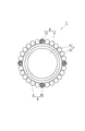
- FIG. 1 is a perspective view of a fiber optic plate according to a first embodiment of the present invention.
- a fiber optic plate (hereinafter referred to as FOP) 1 shown in FIG. 1 is a cylindrical optical device configured by bundling a plurality of optical fibers 7, and has an entrance surface 2 and an exit surface 3.
- the FOP 1 has a function of transmitting the light incident from the incident surface 2 and the image 4 to the output surface 3.
- the FOP 1 is a light guide for an optical device such as an image intensifier, a CRT faceplate, a CCD coupling, a fingerprint detection device, or the like. It is used as a waveguide.
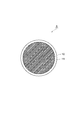
- FIG. 2 is an enlarged perspective view showing the internal structure of the FOP.
- FIG. 3 is a cross-sectional view showing a part of FIG. 2 in an enlarged manner
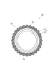
- FIG. 4 is a cross-sectional view showing a part of FIG. 3 in a further enlarged manner.
- the FOP 1 includes a plurality of cores 5 that transmit light, a plurality of clads 6 that cover the outer periphery of each core 5, and a glass body 8 disposed between the fibers 7. It is comprised including.
- the glass body 8 has an absorptivity for absorbing light leaking from the fiber 7 (stray light) and an antibacterial property caused by containing silver oxide.
- the core 5 and the clad 6 constitute a fiber 7.
- the FOP 1 shown in FIGS. 2 to 4 is mainly used for products whose numerical aperture (NA) of the FOP 1 is 1 or less.
- NA numerical aperture
- the core 5 is a fibrous member and is arranged in a direction intersecting the axial direction.
- the core 5 is made of core glass and has a function of transmitting light incident from one end to the other end.
- a plurality of clads 6 are provided corresponding to the plurality of cores 5, respectively, and are formed of clad glass having a refractive index lower than that of the core glass. Since the refractive index of the cladding 6 is lower than the refractive index of the core 5, the light that has entered the core 5 is totally reflected at the boundary surface between the core 5 and the cladding 6. Therefore, the core 5 can propagate light from one end to the other end.
- the glass body 8 is interposed between the plurality of fibers 7.
- the glass body 8 is disposed so as to cover the outer periphery of the fiber 7.
- the glass body 8 is composed of an absorption glass part (first glass part) 9 and an antibacterial glass part (second glass part) 10.
- the absorbing glass portion 9 has a rod-like shape (single fiber), and a plurality of absorbing glass portions 9 are disposed so as to surround the outer peripheral portion of the cladding 6.
- the absorption glass part 9 is formed from an absorption glass having an absorptivity for absorbing stray light.
- the antibacterial glass portion 10 has a rod-like shape (single fiber), and a plurality (four in FIG. 4) are disposed between the outer peripheral portion of the clad 6 and the absorbing glass portion 9. Yes.
- the antibacterial glass part 10 is formed from antibacterial glass having antibacterial properties.
- FIG. 5 is a cross-sectional view showing details of the antibacterial glass portion 10.
- the outer peripheral part of the antimicrobial glass part 10 is coat
- the coated glass portion 11 has the same composition as that of the clad 6 described later.
- the antibacterial glass portion 10 occupies about 6% of the entire end face of the FOP 1 (see FIG. 3).
- the core 5 has a diameter of 30 mm
- the cladding 6 has a diameter of 40 mm and a thickness of 4 mm.
- both the absorption glass part 9 and the antimicrobial glass part 10 are 4 mm in diameter.
- FIG. 7 is a diagram illustrating an example of the composition and characteristics of the core 5, the cladding 6, the absorption glass portion 9, and the antibacterial glass portion 10 described above.
- the content of the composition is shown as a percentage by weight.
- the core glass that forms the core 5 and the clad glass that forms the clad 6 are mainly composed of SiO 2 which is a glass network forming oxide (NWF).
- NWF glass network forming oxide
- the core glass and the clad glass do not become a glass alone, but a glass network modification oxide (NWM) that imparts suitable properties to the glass by melting with NWF, or an intermediate between the two.
- NWM glass network modification oxide
- the absorption glass that forms the absorption glass portion 9 is formed using SiO 2 as a main component. Moreover, the absorption glass contains Fe 3 O 4 . This Fe 3 O 4 has a wide absorption band, and by containing Fe 3 O 4 in the absorption glass part 9, excellent absorption characteristics can be obtained from the visible light region to the near infrared region.
- the absorption glass portion 9 is configured to include other PbO and the like.
- the antibacterial glass forming the antibacterial glass part 10 contains B 2 O 3 , SiO 2 , Al 2 O 3 , Na 2 O, BaO, CaO, and Ag 2 O as raw materials.
- B 2 O 3 acts as an NWF that forms a glass skeleton and contributes to the uniform release of silver ions (Ag ions).
- B 2 O 3 is, are contained approximately 2-3% of the total antimicrobial glass portion 10.
- SiO 2 has an effect as NWF and contributes to prevention of yellowing due to Ag 2 O.
- Al 2 O 3 contributes to the stabilization of silver ions by releasing aluminum ions and bonding with silver ions.
- Na 2 O has an action as an NWM, and has an action for improving the transparency of the antibacterial glass portion 10 and an action for promoting melting and elution of the glass.
- BaO and CaO have an effect of assisting the melting of the glass.
- Ag 2 O silver oxide
- the content of Ag 2 O is of the order of 0.5 wt%.
- a method for creating FOP1 (see FIG. 2) having the above-described configuration is referred to as an EMA (Extra Mural Absorption) method.
- a single fiber is obtained by drawing a composite comprising a core glass that forms the core 5, a clad glass that forms the clad 6, an absorption glass part 9 and an antibacterial glass part 10 through a heating device and a roller.
- a multi-fiber is created using the created single fiber.
- a multi-fiber is obtained by heat-welding a plurality of single fibers by aligning a plurality of single fibers and passing them through a heating device and drawing them with a roller.
- the multi-fibers are aligned with an octagonal mold of a heat press device and pressed at a high temperature, whereby a plurality of multi-fibers are heated and welded to obtain an octagonal ingot.
- FOP1 is obtained by slicing and polishing the ingot perpendicular to the axial direction.
- the glass body 8 includes the antibacterial glass portion 10 made of the antibacterial glass containing Ag 2 O.
- the glass containing silver does not have chemical durability, it has a characteristic that Ag ions are easily released by moisture. And Ag ion has the outstanding antimicrobial effect. Therefore, by the glass body 8 is configured to include an antimicrobial glass portion 10 containing Ag 2 O, may be glass body 8 to obtain a bactericidal effect due to the action of Ag ions. Therefore, FOP1 can have antibacterial properties.
- the antimicrobial glass part 10 is coat
- Ag ions become metallic Ag by coexisting with Fe ions in the glass.
- This metal Ag may reduce the bactericidal effect on the surface of the antibacterial glass. Therefore, the antibacterial glass portion 10 having antimicrobial by containing Ag 2 O, by coating with a coating glass portion 11 containing no Ag 2 O, to avoid coexistence with Fe ions of the absorber glass portions 9 Therefore, it is possible to prevent a decrease in antibacterial effect. As a result, FOP1 can be more reliably given antibacterial properties.
- FIG. 8 shows the composition and properties of each antibacterial glass used to make the FOP.
- the antibacterial effect of this FOP was evaluated by the following procedure.
- the FOP antibacterial test was conducted by a test method according to JIS Z 2801 2000. That is, the test bacteria were inoculated on the surface of a conventional unprocessed test piece containing no Ag 2 O and the test pieces of Examples, and the number of viable bacteria after culturing for 24 hours was measured.
- the antibacterial effect is JIS if the difference in the logarithmic value (antibacterial activity value) between the viable count of the conventional unprocessed test piece and the viable count of the test piece of the example is 2.0 or more.
- Staphylococcus aureus Stipulated in Staphylococcus aureus and Escherichia coli were used as test strains.
- the number of inoculated Staphylococcus aureus is 1.8 ⁇ 10 5 and the number of inoculated Escherichia coli is 2.9 ⁇ 10 5 .
- FIGS. 9 (a) and 9 (b) The results obtained by the above test are shown in FIGS. 9 (a) and 9 (b).
- the results shown in FIGS. 9A and 9B show the results of FOP provided with the antibacterial glass of No. 11 in FIG. As shown in FIGS. 9A and 9B, it was confirmed that the FOPs of the examples had an antibacterial effect.
- FIG. 10 shows the relative transmittance of the conventional FOP and the FOP of the example.
- the FOP has a fiber size of 15 ⁇ m and a thickness of 1.75 mm in both the conventional example and the example.
- the relative transmittance shown in FIG. 10 is the relative transmittance with diffused light of 850 nm.
- FIG. 10 it was confirmed that the relative transmittance of the FOP of the example is substantially the same as the relative transmittance of the conventional FOP, and the optical characteristics are almost the same as the conventional product. Similar results were obtained with respect to image quality.
- FIG. 11 is an enlarged cross-sectional view of a part of the fiber optic plate according to the second embodiment of the present invention.
- the FOP 20 is configured in substantially the same manner as the FOP 1 of the first embodiment, and the first embodiment is that the glass body 21 is configured by an absorption glass portion (glass portion) 22. Is different.
- the outer peripheral part of the clad 6 was coat
- in 2nd Embodiment, by the absorption glass part 22 It is covered with a glass body 21 configured.
- the absorption glass part 22 is formed from a glass material having absorption and antibacterial properties.
- the glass material is composed of the antibacterial glass containing absorbing glass and Ag 2 O in the first embodiment.
- the materials used for the core 5 and the clad 6 are the same as those in the first embodiment.
- the FOP1 is created by the same manufacturing method as the FOP1 of the first embodiment.
- the FOP 20 As described above, in the FOP 20 according to the second embodiment, as in the first embodiment, since the absorption glass portion 22 contains Ag 2 O, the glass body 21 is sterilized by the action of Ag ions. Can be obtained. Accordingly, the FOP 20 can have antibacterial properties.
- the present invention is not limited to the embodiment described above.
- the glass body 8 of the first embodiment is not limited to the above configuration.
- the glass body 8 may be constituted by an absorbent body having an absorptive and antibacterial property and an antibacterial glass portion.
- the glass body 8 may be comprised by the absorber and the antimicrobial glass part which has an absorptivity and antimicrobial property.
- the FOPs 1 and 20 described above are created by the EMA method, but may be created by a method called an ISA (Interstitial Absorption) method.
- FIG. 12 shows an FOP created by the ISA method.
- the FOP 30 created by the ISA method has a configuration in which the clad 31 is integrated to cover the outer peripheral portions of the plurality of cores 5.
- the cladding 31 covers the outer periphery of each of the absorption glass portions 32.
- the absorption glass part 32 is comprised with the material similar to 2nd Embodiment.
- the absorbing glass portions 9, 22, and 32 may be tubular instead of rod-shaped. Further, the clad 6 that covers the antibacterial glass portion 10 is not necessarily provided.
- the fiber optic plate can have antibacterial properties.
Landscapes
- Chemical & Material Sciences (AREA)
- Materials Engineering (AREA)
- Engineering & Computer Science (AREA)
- Chemical Kinetics & Catalysis (AREA)
- General Chemical & Material Sciences (AREA)
- Geochemistry & Mineralogy (AREA)
- Life Sciences & Earth Sciences (AREA)
- Organic Chemistry (AREA)
- Physics & Mathematics (AREA)
- Optics & Photonics (AREA)
- General Physics & Mathematics (AREA)
- Glass Compositions (AREA)
- Optical Fibers, Optical Fiber Cores, And Optical Fiber Bundles (AREA)
Abstract
Description
[第1実施形態]
[第2実施形態]
Claims (5)
- 複数の光ファイバが束ねられて構成されたファイバオプティックプレートであって、
光を伝搬する複数のコアと、
前記コアのそれぞれを被覆するクラッドと、
前記コアの間に配置され、前記コアから漏れて前記クラッドに入射した迷光を吸収する光吸収性、及び酸化銀を含有することにより生じる抗菌性を有するガラス体と、を備えることを特徴とするファイバオプティックプレート。 - 前記ガラス体は、前記吸収性且つ前記抗菌性を有するガラス材料からなるガラス部を含むことを特徴とする請求項1記載のファイバオプティックプレート。
- 前記ガラス体は、前記吸収性を有するガラス材料からなる第1のガラス部と、前記抗菌性を有するガラス材料からなる第2のガラス部と、を含むことを特徴とする請求項1記載のファイバオプティックプレート。
- 前記第2のガラス部は、前記酸化銀を含有しない第3のガラス部によって被覆されていることを特徴とする請求項3記載のファイバオプティックプレート。
- 複数の光ファイバが束ねられて構成されたファイバオプティックプレートの製造方法であって、
光を伝搬する複数のコアと、
前記コアのそれぞれを被覆するクラッドと、
前記コアの間に配置され、前記コアから漏れて前記クラッドに入射した迷光を吸収する光吸収性、及び酸化銀を含有することにより生じる抗菌性を有するガラス体と、を一体化することを特徴とするファイバオプティックプレートの製造方法。
Priority Applications (5)
| Application Number | Priority Date | Filing Date | Title |
|---|---|---|---|
| EP09827434.3A EP2354821B1 (en) | 2008-11-19 | 2009-09-25 | Fiber optic plate and method for producing the same |
| US13/130,013 US20110222827A1 (en) | 2008-11-19 | 2009-09-25 | Fiber optic plate and method for producing the same |
| KR1020117005655A KR101709356B1 (ko) | 2008-11-19 | 2009-09-25 | 파이버 옵틱 플레이트 및 그 제조 방법 |
| US15/640,791 US10209441B2 (en) | 2008-11-19 | 2017-07-03 | Fiber optic plate and method for producing the same |
| US16/238,004 US10802211B2 (en) | 2008-11-19 | 2019-01-02 | Fiber optic plate and method for producing the same |
Applications Claiming Priority (2)
| Application Number | Priority Date | Filing Date | Title |
|---|---|---|---|
| JP2008-295615 | 2008-11-19 | ||
| JP2008295615A JP5171569B2 (ja) | 2008-11-19 | 2008-11-19 | ファイバオプティックプレート及びその製造方法 |
Related Child Applications (2)
| Application Number | Title | Priority Date | Filing Date |
|---|---|---|---|
| US13/130,013 A-371-Of-International US20110222827A1 (en) | 2008-11-19 | 2009-09-25 | Fiber optic plate and method for producing the same |
| US15/640,791 Division US10209441B2 (en) | 2008-11-19 | 2017-07-03 | Fiber optic plate and method for producing the same |
Publications (1)
| Publication Number | Publication Date |
|---|---|
| WO2010058653A1 true WO2010058653A1 (ja) | 2010-05-27 |
Family
ID=42198092
Family Applications (1)
| Application Number | Title | Priority Date | Filing Date |
|---|---|---|---|
| PCT/JP2009/066653 Ceased WO2010058653A1 (ja) | 2008-11-19 | 2009-09-25 | ファイバオプティックプレート及びその製造方法 |
Country Status (6)
| Country | Link |
|---|---|
| US (3) | US20110222827A1 (ja) |
| EP (1) | EP2354821B1 (ja) |
| JP (1) | JP5171569B2 (ja) |
| KR (1) | KR101709356B1 (ja) |
| TW (1) | TWI503584B (ja) |
| WO (1) | WO2010058653A1 (ja) |
Cited By (1)
| Publication number | Priority date | Publication date | Assignee | Title |
|---|---|---|---|---|
| CN109839695A (zh) * | 2017-11-28 | 2019-06-04 | 上海箩箕技术有限公司 | 光纤面板及其调试方法 |
Families Citing this family (6)
| Publication number | Priority date | Publication date | Assignee | Title |
|---|---|---|---|---|
| DE102012207405B3 (de) * | 2012-05-04 | 2013-08-14 | Schott Ag | Glaskeramisches Fügematerial und dessen Verwendung |
| FR2993203B1 (fr) * | 2012-07-11 | 2014-07-18 | Saint Gobain | Vitrage lumineux |
| US10131574B2 (en) | 2013-06-17 | 2018-11-20 | Corning Incorporated | Antimicrobial glass articles and methods of making and using same |
| JP7136534B2 (ja) | 2019-05-07 | 2022-09-13 | 株式会社豊田中央研究所 | 光ファイバレーザ装置 |
| CN111253068B (zh) * | 2020-01-29 | 2022-02-18 | 北方夜视技术股份有限公司 | 高分辨率高调制度倒像器用吸收玻璃及其制备方法 |
| EP3904306B1 (en) * | 2020-04-30 | 2023-06-07 | Schott Ag | Multi-fiber light guide, device with a multi-fiber light guide and method for producing the same |
Citations (5)
| Publication number | Priority date | Publication date | Assignee | Title |
|---|---|---|---|---|
| JP2000203876A (ja) | 1998-12-28 | 2000-07-25 | Nippon Sheet Glass Co Ltd | 抗菌性ガラス及びそのガラスを含有する樹脂組成物 |
| JP2001247333A (ja) | 1999-12-28 | 2001-09-11 | Ishizuka Glass Co Ltd | 抗菌性付与用ガラス組成物、抗菌性繊維、抗菌性撚糸及び抗菌性布状物 |
| JP2005107308A (ja) * | 2003-09-30 | 2005-04-21 | Nissei Electric Co Ltd | ライトガイド |
| WO2005087675A1 (ja) | 2004-03-15 | 2005-09-22 | Koa Glass Co., Ltd. | 抗菌性ガラスおよび抗菌性ガラスの製造方法 |
| JP2008197377A (ja) * | 2007-02-13 | 2008-08-28 | Hamamatsu Photonics Kk | ファイバオプティック |
Family Cites Families (38)
| Publication number | Priority date | Publication date | Assignee | Title |
|---|---|---|---|---|
| US3253500A (en) * | 1964-05-11 | 1966-05-31 | American Optical Corp | Doubly clad light-conducting fibers with the outer cladding being partially light absorbing |
| US4415810A (en) * | 1979-07-05 | 1983-11-15 | Brown Sr Robert L | Device for imaging penetrating radiation |
| JPH0450878A (ja) | 1990-06-14 | 1992-02-19 | Ricoh Co Ltd | 現像剤担持体 |
| JP2890735B2 (ja) | 1990-08-03 | 1999-05-17 | スズキ株式会社 | 鋳 型 |
| JPH04177304A (ja) * | 1990-11-13 | 1992-06-24 | Fukuoka Cloth Kogyo Kk | 走水防止光ケーブル |
| JP3218096B2 (ja) | 1992-09-18 | 2001-10-15 | 泉陽硝子工業株式会社 | 抗菌性ガラス |
| US5319731A (en) * | 1992-10-02 | 1994-06-07 | Eastman Kodak Company | Fiber-optic array of limited acceptance angle |
| JPH06289262A (ja) * | 1993-03-31 | 1994-10-18 | Showa Electric Wire & Cable Co Ltd | 光ファイバケーブル |
| JPH0788236A (ja) | 1993-09-21 | 1995-04-04 | Ace Denken:Kk | パチンコ機の上皿内玉出し装置 |
| JP3486951B2 (ja) | 1994-05-09 | 2004-01-13 | 日本板硝子株式会社 | 抗菌性ガラス組成物 |
| JPH0848539A (ja) | 1994-06-02 | 1996-02-20 | Nippon Sheet Glass Co Ltd | 抗菌性ガラス組成物 |
| JPH0891847A (ja) | 1994-09-28 | 1996-04-09 | Nippon Sheet Glass Co Ltd | ガラス溶解炉 |
| JPH08184717A (ja) * | 1994-11-01 | 1996-07-16 | Nikon Corp | ファインダ装置 |
| JPH08245237A (ja) | 1995-03-09 | 1996-09-24 | Nippon Sheet Glass Co Ltd | 抗菌性ガラス用組成物 |
| JPH08338916A (ja) * | 1995-06-12 | 1996-12-24 | Hamamatsu Photonics Kk | ファイバー光学プレート |
| JPH10158037A (ja) | 1996-11-27 | 1998-06-16 | Asahi Glass Co Ltd | 抗菌性ガラス及びその製造方法 |
| JPH10160948A (ja) * | 1996-12-04 | 1998-06-19 | Hamamatsu Photonics Kk | ファイバ光学プレート |
| JPH11228186A (ja) | 1998-02-09 | 1999-08-24 | Nippon Parkerizing Co Ltd | ガラス、ガラスの製造方法、及び強化抗菌ガラス用組成物 |
| JP3349450B2 (ja) | 1998-08-24 | 2002-11-25 | 関西ペイント株式会社 | レジストパターン形成方法 |
| JP2000169185A (ja) | 1998-12-11 | 2000-06-20 | Nippon Electric Glass Co Ltd | 抗菌性結晶化ガラス物品とその製造方法 |
| JP2000191339A (ja) | 1998-12-28 | 2000-07-11 | Koa Glass Kk | 溶解性ガラス、抗菌性樹脂組成物、および抗菌性成形品 |
| JP2000327364A (ja) | 1999-05-21 | 2000-11-28 | Ishizuka Glass Co Ltd | 抗菌性ガラス組成 |
| JP2001097735A (ja) | 1999-10-01 | 2001-04-10 | Nippon Electric Glass Co Ltd | 抗菌性ガラス及びその製造方法 |
| JP2000313624A (ja) | 2000-01-01 | 2000-11-14 | Ion Kogaku Shinko Zaidan | 抗菌性ガラスの製造方法 |
| JP2001226139A (ja) | 2000-02-15 | 2001-08-21 | Nippon Sheet Glass Co Ltd | 抗菌性ガラスおよびそれを含有する樹脂組成物 |
| JP2001240426A (ja) | 2000-02-25 | 2001-09-04 | Nippon Sheet Glass Co Ltd | 抗菌性ガラスおよびそれを含有する樹脂組成物 |
| JP2002037643A (ja) | 2000-07-24 | 2002-02-06 | Nippon Electric Glass Co Ltd | 抗菌性ガラス及びその樹脂組成物 |
| JP3744779B2 (ja) | 2000-08-29 | 2006-02-15 | 松下電器産業株式会社 | パルス発生装置 |
| JP2003242488A (ja) | 2002-02-18 | 2003-08-29 | Casio Comput Co Ltd | 撮像装置 |
| JP4005393B2 (ja) | 2002-03-13 | 2007-11-07 | 東亞合成株式会社 | 抗菌効果に優れる銀系ガラス質抗菌剤の製造方法 |
| US7221835B1 (en) * | 2003-11-25 | 2007-05-22 | Schott Corporation | Ion-reduction-blackened extra-mural absorbing media adapted for inclusion in image-conducting optical fiber arrays and methods of fabricating the same |
| JP4086893B2 (ja) * | 2005-05-10 | 2008-05-14 | 興亜硝子株式会社 | 抗菌性繊維の製造方法 |
| KR200396126Y1 (ko) * | 2005-07-06 | 2005-09-15 | 전원희 | 암실용 항균 탈취구 |
| JPWO2007018287A1 (ja) * | 2005-08-11 | 2009-02-19 | 協和発酵ケミカル株式会社 | 樹脂組成物 |
| US7960465B2 (en) * | 2006-06-30 | 2011-06-14 | Johnson & Johnson Vision Care, Inc. | Antimicrobial lenses, processes to prepare them and methods of their use |
| US20080085326A1 (en) * | 2006-10-04 | 2008-04-10 | Hai Xiong Ruan | Antimicrobial material compositions enriched with different active oxygen species |
| US20080286713A1 (en) * | 2007-05-16 | 2008-11-20 | Puneet Nanda | Toothbrush with illumination system |
| US20150090475A1 (en) * | 2013-03-15 | 2015-04-02 | General Cable Technologies Corporation | Cables having an antimicrobial coating |
-
2008
- 2008-11-19 JP JP2008295615A patent/JP5171569B2/ja not_active Expired - Fee Related
-
2009
- 2009-09-25 US US13/130,013 patent/US20110222827A1/en not_active Abandoned
- 2009-09-25 KR KR1020117005655A patent/KR101709356B1/ko not_active Expired - Fee Related
- 2009-09-25 WO PCT/JP2009/066653 patent/WO2010058653A1/ja not_active Ceased
- 2009-09-25 EP EP09827434.3A patent/EP2354821B1/en not_active Not-in-force
- 2009-10-08 TW TW098134134A patent/TWI503584B/zh not_active IP Right Cessation
-
2017
- 2017-07-03 US US15/640,791 patent/US10209441B2/en active Active
-
2019
- 2019-01-02 US US16/238,004 patent/US10802211B2/en active Active
Patent Citations (5)
| Publication number | Priority date | Publication date | Assignee | Title |
|---|---|---|---|---|
| JP2000203876A (ja) | 1998-12-28 | 2000-07-25 | Nippon Sheet Glass Co Ltd | 抗菌性ガラス及びそのガラスを含有する樹脂組成物 |
| JP2001247333A (ja) | 1999-12-28 | 2001-09-11 | Ishizuka Glass Co Ltd | 抗菌性付与用ガラス組成物、抗菌性繊維、抗菌性撚糸及び抗菌性布状物 |
| JP2005107308A (ja) * | 2003-09-30 | 2005-04-21 | Nissei Electric Co Ltd | ライトガイド |
| WO2005087675A1 (ja) | 2004-03-15 | 2005-09-22 | Koa Glass Co., Ltd. | 抗菌性ガラスおよび抗菌性ガラスの製造方法 |
| JP2008197377A (ja) * | 2007-02-13 | 2008-08-28 | Hamamatsu Photonics Kk | ファイバオプティック |
Non-Patent Citations (1)
| Title |
|---|
| See also references of EP2354821A4 * |
Cited By (2)
| Publication number | Priority date | Publication date | Assignee | Title |
|---|---|---|---|---|
| CN109839695A (zh) * | 2017-11-28 | 2019-06-04 | 上海箩箕技术有限公司 | 光纤面板及其调试方法 |
| CN109839695B (zh) * | 2017-11-28 | 2020-08-14 | 上海箩箕技术有限公司 | 光纤面板及其调试方法 |
Also Published As
| Publication number | Publication date |
|---|---|
| JP2010122436A (ja) | 2010-06-03 |
| EP2354821A1 (en) | 2011-08-10 |
| TW201030400A (en) | 2010-08-16 |
| US20190154915A1 (en) | 2019-05-23 |
| US20170307816A1 (en) | 2017-10-26 |
| TWI503584B (zh) | 2015-10-11 |
| US10209441B2 (en) | 2019-02-19 |
| KR20110086546A (ko) | 2011-07-28 |
| US20110222827A1 (en) | 2011-09-15 |
| KR101709356B1 (ko) | 2017-02-22 |
| EP2354821A4 (en) | 2012-05-09 |
| EP2354821B1 (en) | 2015-11-11 |
| JP5171569B2 (ja) | 2013-03-27 |
| US10802211B2 (en) | 2020-10-13 |
Similar Documents
| Publication | Publication Date | Title |
|---|---|---|
| US10802211B2 (en) | Fiber optic plate and method for producing the same | |
| KR101514086B1 (ko) | 파이버 옵틱 | |
| TWI572480B (zh) | 經層壓及離子交換之強化玻璃疊層 | |
| US3784386A (en) | Cladding glasses for photochromic optical fibers | |
| CN106772791B (zh) | 低杂散光串扰型光纤传像元件及其制备方法 | |
| JP2014141363A (ja) | 化学強化可能なガラス,ガラス板及び化学強化カバーガラス | |
| WO2010011265A3 (en) | Double-clad optical fibers and devices with double-clad optical fibers | |
| TW593195B (en) | Multicomponent glass, glass fiber, twister and taper | |
| JPWO2022045011A5 (ja) | ||
| US3981706A (en) | Method for making flexible colored fiber optic device | |
| JPWO2022065000A5 (ja) | ||
| CN112960901A (zh) | 一种柔性光纤传像束及其制备方法和应用 | |
| CN117534319B (zh) | 一种超窄扭丝区光纤倒像器的制备方法及应用 | |
| EP0927705B1 (en) | Fiber optic plate | |
| DE1038338T1 (de) | Doppelt ummantelte, mit seltenen erden dotierte optische faser | |
| JP2019053268A (ja) | 可視光を透過し、且つ近赤外線及び赤外線をカットするガラス積層体 | |
| JPH07113920A (ja) | イメージファイバー | |
| JPS58149007A (ja) | マルチプルフアイバ | |
| JP4046786B2 (ja) | ファイバオプティックプレート | |
| JPH0971436A5 (ja) | ||
| CH710243B1 (de) | Verbundscheibe für Schutzverglasung mit Funktionsbeschichtung. | |
| JP2509330B2 (ja) | イメ―ジファイバおよびその製造方法 | |
| CN108754783A (zh) | 一种具有反射、辐射制冷和免烫功能的面层织物 | |
| EP4582842B1 (en) | Optical fiber image inverter with ultra-narrow twisted fiber area and preparation method therefor and application thereof, and related composition | |
| CN119738914B (zh) | 一种低串扰高分辨率传像光纤及其制备方法 |
Legal Events
| Date | Code | Title | Description |
|---|---|---|---|
| 121 | Ep: the epo has been informed by wipo that ep was designated in this application |
Ref document number: 09827434 Country of ref document: EP Kind code of ref document: A1 |
|
| ENP | Entry into the national phase |
Ref document number: 20117005655 Country of ref document: KR Kind code of ref document: A |
|
| WWE | Wipo information: entry into national phase |
Ref document number: 13130013 Country of ref document: US |
|
| NENP | Non-entry into the national phase |
Ref country code: DE |
|
| WWE | Wipo information: entry into national phase |
Ref document number: 2009827434 Country of ref document: EP |