WO2010061916A1 - 発電部材およびこれを用いた発電装置ならびに発電システム - Google Patents
発電部材およびこれを用いた発電装置ならびに発電システム Download PDFInfo
- Publication number
- WO2010061916A1 WO2010061916A1 PCT/JP2009/070036 JP2009070036W WO2010061916A1 WO 2010061916 A1 WO2010061916 A1 WO 2010061916A1 JP 2009070036 W JP2009070036 W JP 2009070036W WO 2010061916 A1 WO2010061916 A1 WO 2010061916A1
- Authority
- WO
- WIPO (PCT)
- Prior art keywords
- power generation
- piezoelectric element
- pressing
- pressing member
- support member
- Prior art date
- Legal status (The legal status is an assumption and is not a legal conclusion. Google has not performed a legal analysis and makes no representation as to the accuracy of the status listed.)
- Ceased
Links
Images








Classifications
-
- E—FIXED CONSTRUCTIONS
- E01—CONSTRUCTION OF ROADS, RAILWAYS, OR BRIDGES
- E01C—CONSTRUCTION OF, OR SURFACES FOR, ROADS, SPORTS GROUNDS, OR THE LIKE; MACHINES OR AUXILIARY TOOLS FOR CONSTRUCTION OR REPAIR
- E01C9/00—Special pavings; Pavings for special parts of roads or airfields
-
- F—MECHANICAL ENGINEERING; LIGHTING; HEATING; WEAPONS; BLASTING
- F03—MACHINES OR ENGINES FOR LIQUIDS; WIND, SPRING, OR WEIGHT MOTORS; PRODUCING MECHANICAL POWER OR A REACTIVE PROPULSIVE THRUST, NOT OTHERWISE PROVIDED FOR
- F03G—SPRING, WEIGHT, INERTIA OR LIKE MOTORS; MECHANICAL-POWER PRODUCING DEVICES OR MECHANISMS, NOT OTHERWISE PROVIDED FOR OR USING ENERGY SOURCES NOT OTHERWISE PROVIDED FOR
- F03G7/00—Mechanical-power-producing mechanisms, not otherwise provided for or using energy sources not otherwise provided for
- F03G7/08—Mechanical-power-producing mechanisms, not otherwise provided for or using energy sources not otherwise provided for recovering energy derived from swinging, rolling, pitching or like movements, e.g. from the vibrations of a machine
- F03G7/081—Mechanical-power-producing mechanisms, not otherwise provided for or using energy sources not otherwise provided for recovering energy derived from swinging, rolling, pitching or like movements, e.g. from the vibrations of a machine recovering energy from moving road or rail vehicles, e.g. collecting vehicle vibrations in the vehicle tyres or shock absorbers
- F03G7/083—Mechanical-power-producing mechanisms, not otherwise provided for or using energy sources not otherwise provided for recovering energy derived from swinging, rolling, pitching or like movements, e.g. from the vibrations of a machine recovering energy from moving road or rail vehicles, e.g. collecting vehicle vibrations in the vehicle tyres or shock absorbers using devices on streets or on rails
- F03G7/087—Mechanical-power-producing mechanisms, not otherwise provided for or using energy sources not otherwise provided for recovering energy derived from swinging, rolling, pitching or like movements, e.g. from the vibrations of a machine recovering energy from moving road or rail vehicles, e.g. collecting vehicle vibrations in the vehicle tyres or shock absorbers using devices on streets or on rails magnetic or electromagnetic devices, e.g. linear electric generators
-
- H—ELECTRICITY
- H02—GENERATION; CONVERSION OR DISTRIBUTION OF ELECTRIC POWER
- H02N—ELECTRIC MACHINES NOT OTHERWISE PROVIDED FOR
- H02N2/00—Electric machines in general using piezoelectric effect, electrostriction or magnetostriction
- H02N2/18—Electric machines in general using piezoelectric effect, electrostriction or magnetostriction producing electrical output from mechanical input, e.g. generators
-
- H—ELECTRICITY
- H10—SEMICONDUCTOR DEVICES; ELECTRIC SOLID-STATE DEVICES NOT OTHERWISE PROVIDED FOR
- H10N—ELECTRIC SOLID-STATE DEVICES NOT OTHERWISE PROVIDED FOR
- H10N30/00—Piezoelectric or electrostrictive devices
- H10N30/30—Piezoelectric or electrostrictive devices with mechanical input and electrical output, e.g. functioning as generators or sensors
- H10N30/308—Membrane type
Definitions
- the present invention relates to a power generation member having a function of generating power using pressure energy generated when a person walks or vibration energy generated when a car or a train travels, and a power generation apparatus and a power generation system using the power generation member. is there.
- clean energy that does not involve CO 2 emissions includes the energy of pressure generated when people walk on floors and stairs of public facilities such as stations and airports, department stores, and roads, bridges, parking lots or railroad tracks
- a power generation system that generates electric power by taking out the voltage generated by distorting piezoelectric ceramics by using vibration energy generated when a train or the like travels has attracted attention.
- This power generation system includes a power generation device using a power generation member including piezoelectric ceramics, and some examples of such power generation members, power generation devices, and power generation systems are proposed in Patent Documents 1 to 3. .
- Patent Document 1 a piezoelectric member is provided in a passage through which a moving object including a person, a vehicle, or a train passes, and electric power generated by pressure applied to the piezoelectric member by passing the moving object on the piezoelectric member is generated.
- a power generation system to be taken out has been proposed. According to this, it is possible to configure a power generation system in existing facilities such as a station premises, and the power supply source is the movement of people and vehicles themselves, which can generate power very efficiently. Is.
- Patent Document 2 proposes a power generation device in which a pressing power generation element is disposed on the floor of the staircase and the floor around the elevator and the pressing power generation element is connected to a charging device. According to this, it is possible to generate power by stepping on the pressing power generation element when going up and down the stairs, and there is almost no failure even when used for a long time. It can be done.
- Patent Document 3 proposes a floor board material having a structure in which piezoelectric ceramics are sandwiched between electrodes in a building floor board material, and having a power generation function by an external load pressure.
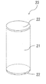
- FIG. 16 is a perspective view of a piezoelectric element in which metal electrodes are attached to both ends of a piezoelectric ceramic material described in Patent Document 3.
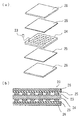
- FIG. 17 shows the floor board material provided with the piezoelectric element described in Patent Document 3, (a) is an exploded view of the basic structure, and (b) is a cross-sectional view of the floor board material.
- metal electrodes 22 are formed on both ends of a piezoelectric ceramic 21 processed into a cylindrical shape by vapor deposition or the like.
- the floor board material 20 is electrically connected to the metal electrode 22 by fitting the piezoelectric elements 23 into the plurality of holes of the support material 24 having high electrical characteristics.
- the upper and lower sides are sandwiched between metal plates 25 so as to be conductive, and the upper and lower sides are sandwiched between floor plate materials 26 that are normally used, and these are in close contact with each other.
- Patent Document 1 is an epoch-making power generation system that does not require the construction of a dedicated facility based on the property that a piezoelectric member can be used for power generation, in order to take out a high voltage.
- the configuration of the piezoelectric member and the efficient power generation method have not been sufficiently disclosed.
- the power generation device described in Patent Document 2 can also generate power by stepping on the pressure power generation element with a foot, although it is a power generation device that can effectively use energy, there is a method for pressing the pressure power generation element. It has not been fully studied, and high power has not always been obtained.
- the floor board material 20 described in Patent Document 3 specifically shows a method of generating power by taking out a voltage
- the piezoelectric ceramic 21 is cylindrical, the pressure applied by the person's weight or the like is applied to the floor board. Even if it was transmitted to the piezoelectric element 23 via the material 26 and the metal plate 25, the piezoelectric ceramic 21 could not be sufficiently distorted, and high power could not be obtained.
- the present invention has been devised to solve the above-described problems, and an object thereof is to provide a power generation member with high power generation, a power generation device using the power generation device, and a power generation system.
- the power generation member of the present invention includes a piezoelectric element in which electrodes are formed on both main surfaces of a plate-like piezoelectric ceramic, a pressing member that presses the piezoelectric element from one main surface side, and the piezoelectric element on the other main surface side. And a supporting member that supports the peripheral portion of the piezoelectric element, and the pressing member presses the piezoelectric element with a flat pressing surface inside the supporting member. It is characterized by doing.
- the power generation member of the present invention includes a piezoelectric element having electrodes formed on both main surfaces of a plate-like piezoelectric ceramic, a pressing member that presses the piezoelectric element from one main surface side, and the piezoelectric element on the other main surface.
- the power generation member of the present invention includes a piezoelectric element having electrodes formed on both main surfaces of a plate-like piezoelectric ceramic, a pressing member that presses the piezoelectric element from one main surface side, and the piezoelectric element on the other main surface.
- the power generation member is provided with a support member supported on the side, and the shape in plan view is a triangle shape, a quadrangular shape, a hexagonal shape, or an octagonal shape.
- the power generation member of the present invention is characterized in that, in the above configuration, the pressing member is made of a material having a hardness lower than that of the support member.
- the power generating member of the present invention is characterized in that, in any one of the configurations described above, the piezoelectric ceramic is made of lead zirconate titanate.
- the power generating member of the present invention is characterized in that, in any one of the above-described configurations, the piezoelectric ceramic contains potassium niobate, sodium, and lithium as main components, and includes calcium titanate and bismuth ferrate. .
- a plurality of power generation members of the present invention having any one of the above configurations are arranged in a plane, and each of the pressing members is held by a plate-like first cover member, The support member is held by a plate-like second cover member.
- the power generator of the present invention is characterized in that, in the above configuration, the pressing member is formed integrally with the first cover member.
- the power generator of the present invention is characterized in that, in the above configuration, the support member is formed integrally with the second cover member.
- the power generation system of the present invention is characterized by comprising the power generation device of the present invention having any one of the above configurations and a DC / AC converter connected through a circuit including a diode and a capacitor. is there.
- the power generation system of the present invention is characterized in that the power generation device of the present invention having any one of the above configurations is arranged below the floor, stairs, road, bridge, parking lot, or track.
- a piezoelectric element in which electrodes are formed on both main surfaces of a plate-like piezoelectric ceramic, a pressing member that presses the piezoelectric element from one main surface side, and the piezoelectric element on the other main surface side And a supporting member that supports the peripheral portion of the piezoelectric element, and the pressing member presses the piezoelectric element with a flat pressing surface inside the supporting member. Ceramics can be sufficiently bent and large strain can be obtained, and cancellation of generated charges can be reduced, so that high power can be obtained efficiently.
- the piezoelectric element in which electrodes are formed on both main surfaces of the plate-shaped piezoelectric ceramic, the pressing member that presses the piezoelectric element from one main surface side, and the piezoelectric element on the other main surface A power generation member comprising a support member supported on the side, the support member supports a peripheral portion of the piezoelectric element, and the pressing member presses the piezoelectric element with an annular pressing surface inside the support member. Piezoelectric ceramics can be sufficiently bent to obtain large strains, and canceling of generated charges can be reduced, so that high power can be obtained efficiently.
- the weight of the pressing member can be reduced as compared with a planar pressing member, and the pressing member itself can be an annular member. Since it can reduce, the weight reduction of the electric power generating apparatus arrange
- Power generation member comprising a support member supported on the side, and since the shape in plan view is triangular, quadrangular, hexagonal or octagonal, there is almost no wasted space between the power generation members Since a plurality of power generating members can be arranged closely in a plane in the state, high power can be obtained efficiently.
- the pressing member when the pressing member is made of a material whose hardness is lower than that of the support member, a large pressure energy generated when a person walks or a large vibration energy generated when a vehicle or the like travels generates a power generation member. Even in this case, the pressing member absorbs and relaxes energy due to large pressure and vibration, and the supporting member can be supported while suppressing excessive deformation of the piezoelectric element, so that the piezoelectric ceramic constituting the piezoelectric element is broken. Can be suppressed.
- the piezoelectric ceramic is made of lead zirconate titanate
- the ferroelectricity which is one of the characteristics affecting the power generation amount, is high, so that higher power can be obtained.
- the piezoelectric ceramic is composed mainly of potassium niobate / sodium / lithium and contains calcium titanate and bismuth ferrate
- a discontinuous portion referred to as a secondary phase transition that is transformed from a low-temperature side ferroelectric phase to a high-temperature side ferroelectric phase due to the temperature change rate of the resonance frequency and the piezoelectric constant g33 is less likely to occur. Can be stabilized.
- the lead-free composition can be obtained, an environment-friendly power generation member can be obtained.
- a plurality of power generation members of the present invention are arranged in a plane, each pressing member is held by a plate-like first cover member, and each supporting member is a plate.
- the second cover member is held in the shape, power can be generated by efficiently using pressure energy generated when a person walks or vibration energy generated when a vehicle or the like travels.
- the pressing member and the supporting member are respectively held by the first cover member and the second cover member, and energy due to pressure and vibration is not transmitted to a specific power generating member but is distributed and transmitted to a plurality of power generating members. Therefore, the power generation member is less likely to be damaged and can be used over a long period of time.
- the pressing member when the pressing member is formed integrally with the first cover member, the pressing member and the first cover member are not simply in contact but formed integrally. Therefore, the relative positional relationship between the piezoelectric element and the pressing member does not change.
- the power generation using the energy of the pressure generated when the person walks or the vibration energy generated when the vehicle travels is repeated. However, since the adhesion does not peel off and the coupling member such as a screw does not loosen, high power can be obtained efficiently over a long period of time.
- the relative positional relationship between the piezoelectric element and the support member does not change. Can be obtained efficiently over a long period of time. Further, since the support member and the second cover member are integrally formed, the joining or joining process can be reduced.
- the power generation device of the present invention when the power generation device of the present invention and a DC / AC converter connected via a circuit including a diode and a capacitor are provided, pressure energy generated when a person walks
- the piezoelectric element is formed by a pressing member having a flat pressing surface held by the first cover member, a pressing member having an annular pressing surface, and eventually an annular pressing member, by vibration energy generated when the vehicle travels. Since the supporting member pressed and held by the second cover member supports the peripheral portion of the piezoelectric element, the piezoelectric ceramic is sufficiently bent and distorted, and the voltage generated by this distortion passes through the diode to the capacitor.
- the power generation device provided in the power generation system of the present invention, if the shape of the power generation device in plan view is triangular, quadrangular, hexagonal, or octagonal, there is a useless space between the power generation devices of that shape. Since a plurality of power generators can be arranged closely in a plane with almost no state, high power can be obtained efficiently. Note that the plurality of power generation devices at this time do not have to have the same shape in plan view, and may be power generation devices having different shapes as long as they can be combined and closely arranged in a planar shape. Is.
- the power generation device of the present invention when the power generation device of the present invention is disposed below the floor, stairs, road, bridge, parking lot or track, the energy of pressure generated when a person walks or Since electric power can be generated using vibration energy generated when the vehicle or the like travels, it is effective as an energy saving measure, and a clean power generation system that does not involve CO2 emission can be achieved.
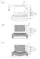
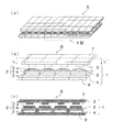
- FIG. 1 An example of an embodiment of a power generation member of the present invention is shown, (a) is a perspective view, and (b) is a cross-sectional view taken along line A-A ′ in (a). Further, (c) is a cross-sectional view showing a state where the piezoelectric element is pressed by the pressing member.
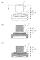
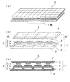
- FIG. 1 Another example of the embodiment of the power generation member of the present invention is shown, (a) is a perspective view, (b) is a cross-sectional view taken along line B-B 'in (a). Further, (c) is a cross-sectional view showing a state where the piezoelectric element is pressed by the pressing member.
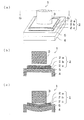
- FIG. 1 Another example of the embodiment of the power generation member of the present invention is shown, (a) is a perspective view, (b) is a sectional view taken along line C-C 'in (a). Further, (c) is a cross-sectional view showing a state where the piezoelectric element is pressed by the pressing member.
- An example of an embodiment of a power generation member of the present invention is shown, (a) is a perspective view, and (b) is a sectional view taken along line D-D 'in (a). Moreover, (c) is a sectional view showing a state where the piezoelectric element is pressed by an annular pressing member having an annular pressing surface.
- (a) is a perspective view
- (b) is sectional drawing in the E-E 'line in (a).
- (c) is a sectional view showing a state where the piezoelectric element is pressed by an annular pressing member having an annular pressing surface.
- FIG. 1 is a perspective view
- FIG. 1 is a perspective view
- FIG. 1 is a perspective view
- FIG. 1 is a cross-sectional view taken along line F-F 'in (a).
- (c) is a sectional view showing a state where the piezoelectric element is pressed by an annular pressing member having an annular pressing surface.
- FIG. 1 Another example of the embodiment of the power generation member of the present invention is shown, (a) is a perspective view, (b) is a cross-sectional view taken along line G-G 'in (a). Further, (c) is a cross-sectional view showing a state where the piezoelectric element is pressed by the pressing member.
- the other example of embodiment of the electric power generation member of this invention is shown, (a) is a perspective view, (b) is sectional drawing in the H-H 'line
- FIG. 1 An example of arrangement
- positioning of the electric power generation member of this invention is shown, (a) is a triangle-shaped combination, (b) is a square-shaped combination, (c) is a combination of a hexagonal shape and a triangular shape, and (d) is an octagonal shape. It is a schematic diagram of the combination with a square shape.
- An example of embodiment of the electric power generating apparatus using the electric power generation member of this invention is shown, (a) is a perspective view, (b) is an enlarged view of the V section in (a), (c) is (b) 2 is a cross-sectional view taken along line JJ ′ in FIG.
- the other example of embodiment of the electric power generating apparatus using the electric power generation member of this invention is shown, (a) is a perspective view, (b) is an enlarged view of the W section in (a), (c) is It is sectional drawing in the KK 'line
- the other example of embodiment of the electric power generating apparatus using the electric power generation member of this invention is shown, (a) is a perspective view, (b) is an enlarged view of the X section in (a), (c) is It is sectional drawing in the LL 'line in (b).
- the other example of embodiment of the electric power generating apparatus using the electric power generation member of this invention is shown, (a) is a perspective view, (b) is an enlarged view of the Y section in (a), (c) is It is sectional drawing in the MM 'line in (b). It is a schematic block diagram which shows an example of embodiment of the electric power generation system using the electric power generating apparatus of this invention. It is a schematic block diagram which shows the other example of embodiment of the electric power generation system using the electric power generating apparatus of this invention. It is a perspective view of the piezoelectric element which attached the metal electrode to the both ends of the conventional piezoelectric ceramic material.
- the floor board raw material provided with the conventional piezoelectric element is shown, (a) is an exploded view of basic structure, (b) is sectional drawing of a floor board raw material.
- Power generation member 2 Piezoelectric element 2a: Electrode 2b: Piezoelectric ceramics 2c: Electrode 3: Press member 4: Support member 5: Holding member 6: Power generation device 7: First cover member 8: Second cover member 9: Power generation system 10a, 10b: Diode 11: Capacitor 12: DC / AC converter
- FIG. 1A is a perspective view
- FIG. 1B is a cross-sectional view taken along line AA ′ in FIG.
- (c) is a cross-sectional view showing a state where the piezoelectric element is pressed by the pressing member.
- the power generation member 1 of the example shown in FIG. 1 includes a piezoelectric element 2 having electrodes 2a and 2c formed on both main surfaces of a plate-like piezoelectric ceramic 2b, and a pressing member 3 that presses the piezoelectric element 2 from one main surface side.
- the power generation member 1 includes a support member 4 that supports the piezoelectric element 2 on the other main surface side.
- the piezoelectric ceramic 2b constituting the piezoelectric element 2 is a ceramic having a circular and plate-like piezoelectricity.
- PZT lead zirconate titanate
- PT lead titanate
- BT barium titanate
- a bismuth (Bi) layered compound, a tungsten bronze compound, or a compound having a perovskite structure such as a niobium (Nb) acid alkali compound may be used.
- the electrode 2a is a circular layered electrode formed on one main surface of the piezoelectric ceramic 2b
- the electrode 2c is a circular plate electrode formed on the other main surface of the piezoelectric ceramic 2b.
- the electrode 2c is a circular plate-like electrode, it can have a function of holding the piezoelectric ceramic 2b on which the electrode 2a is formed.
- the material of the electrodes 2a and 2c it is preferable to form at least one selected from gold, silver, copper, brass and palladium having high electrical conductivity.
- the pressing member 3 presses the piezoelectric element 2 so that the piezoelectric element 2 does not break, and the support member 4 must support the piezoelectric element 2 so that the piezoelectric element 2 does not break.
- What is necessary is just to form from the material which has, for example, at least 1 sort (s) chosen from austenitic stainless steels, such as SUS303, SUS304, SUS316, aluminum alloys, such as 3000 series, 5000 series, rubber
- the shape of the pressing surface of the pressing member 3 is a flat shape. If the shape of the pressing surface of the pressing member 3 is hemispherical or curved, a negative strain is generated at the center of the pressed piezoelectric ceramic 2b, and the sign of the strain is reversed as it proceeds in the radial direction from the center toward the outer periphery. However, a positive strain is generated on the outer periphery of the piezoelectric ceramic 2b, and the charge generated due to the presence of the positive and negative strains is canceled, and the voltage that can be taken out becomes small. On the other hand, if the shape of the pressing surface of the pressing member 3 is a flat shape, the position where the sign of strain is reversed shifts to the outer peripheral side, and the cancellation of the generated charges can be reduced.
- the support member 4 supports the peripheral portion of the piezoelectric element 2, and the support member 4 can sufficiently deflect the piezoelectric ceramic 2 b by supporting the peripheral portion of the piezoelectric element 2. As a result, a large strain can be obtained.
- the support member 4 supports the peripheral portion of the piezoelectric element 2, and the pressing member 3 is the power generation member 1 that presses the piezoelectric element 2 with a flat pressing surface inside the supporting member 4.
- the piezoelectric ceramic 2b is sufficiently bent by the energy of pressure generated when walking or the vibration energy generated when a car travels, so that a large strain can be obtained and the generated charges. Therefore, high power can be obtained efficiently.
- FIG. 2 shows another example of the embodiment of the power generating member of the present invention
- (a) is a perspective view
- (b) is a cross-sectional view taken along line B-B ′ in (a).
- (c) is a cross-sectional view showing a state where the piezoelectric element is pressed by the pressing member.
- the pressing surface of the pressing member 3 can be widened.
- the power generation member 1 has a configuration in which the main surface of the piezoelectric element 2 is a flat surface and the pressing surface of the pressing member 3 is widened, the sign of strain is reversed as compared with the power generation member 1 of the example shown in FIG. The position to be shifted is shifted to the outer peripheral side, and the cancellation of generated charges can be reduced.
- FIG. 3A and 3B show another example of the embodiment of the power generation member of the present invention, in which FIG. 3A is a perspective view, and FIG. 3B is a cross-sectional view taken along line C-C ′ in FIG. Further, (c) is a cross-sectional view showing a state where the piezoelectric element is pressed by the pressing member.
- a piezoelectric element 2 in which layered electrodes 2a and 2c are formed on both principal surfaces of a plate-like piezoelectric ceramic 2b, a holding member 5 that holds the piezoelectric element 2, and a piezoelectric element.
- a pressing member 3 that presses 2 from one main surface side, and a support member 4 that supports the piezoelectric element 2 on the other main surface side. As such a configuration, it is also possible to generate power by taking out a voltage.
- the holding member 5 is formed of one selected from gold, silver, copper, brass, palladium, SUS (stainless steel), phosphor bronze, titanium copper, oxygen-free copper, tough pitch copper, and phosphorus deoxidized copper having high electrical conductivity. It is preferable to do.
- FIG. 4A and 4B show an example of an embodiment of the power generation member of the present invention, in which FIG. 4A is a perspective view, and FIG. 4B is a cross-sectional view taken along line D-D ′ in FIG. Moreover, (c) is a sectional view showing a state where the piezoelectric element is pressed by an annular pressing member having an annular pressing surface.
- the configuration of the power generation member 1 other than that the pressing surface of the pressing member 3 is annular and the pressing member 3 itself is annular is the content described with reference to FIG. Because of this, duplicate description is omitted.
- the support member 4 supports the periphery of the piezoelectric element 2, and the pressing member 3 presses the piezoelectric element 2 inside the support member 4 with an annular pressing surface.
- the piezoelectric ceramic 2b is sufficiently bent by the energy of the pressure generated when a person walks or the vibration energy generated when a car or the like travels. Large distortion can be obtained, and cancellation of generated charges can be reduced, so that high power can be obtained efficiently.
- the pressing surface of the pressing member 3 is annular, the vicinity of the center of the piezoelectric element 2 is not pressed, and the outer peripheral side of the piezoelectric element 2 is pressed. It is possible to reduce the cancellation of the electric charges generated by shifting to the outer peripheral side of the piezoelectric element 2.
- the annular pressing surface of the pressing member 3 may be anything that does not press the vicinity of the center of the piezoelectric element 2 and presses the piezoelectric element 2 inside the support member 4.
- the pressing surface of the pressing member 3 constituting the power generation member 1 is annular, the weight can be reduced as compared with a planar pressing surface, and as a result, the pressing member 3 is annular, thereby providing one power generation member. Since the weight of 1 can be reduced, it is possible to reduce the weight of the power generation apparatus in which a plurality of power generation members 1 are arranged in a plane. Furthermore, since the power generation device can be reduced in weight, the burden of carrying the power generation device can be reduced.
- the pressing member 3 having an annular pressing surface is not limited to the entire pressing member 3 having an annular shape as in this example, and has a concave portion in the central portion on the pressing surface side. In this case, it is possible to reduce the weight of at least the concave portion.
- FIG. 5 shows another example of the embodiment of the power generating member of the present invention
- (a) is a perspective view
- (b) is a cross-sectional view taken along the line E-E 'in (a).
- (c) is a sectional view showing a state where the piezoelectric element is pressed by an annular pressing member having an annular pressing surface.
- the electrode 2a is formed so that the main surface of the piezoelectric element 2 is a flat surface without a step, so that the annular pressing member 3 that is a pressing member 3 having an annular pressing surface. It is possible to shift the pressing position by increasing the diameter to the outer peripheral side of the piezoelectric element 2. In this way, by shifting the position where the main surface of the piezoelectric element 2 is flat and the diameter of the pressing surface of the annular pressing member 3 having the annular pressing surface is increased toward the outer peripheral side of the piezoelectric element 2, Compared with the power generation member 1 of the example shown in FIG. 4, the position where the sign of the strain is reversed shifts to the outer peripheral side, so that cancellation of generated charges can be reduced.
- FIG. 6A and 6B show another example of the embodiment of the power generation member of the present invention.
- FIG. 6A is a perspective view
- FIG. 6B is a cross-sectional view taken along line F-F ′ in FIG.
- (c) is a sectional view showing a state where the piezoelectric element is pressed by an annular pressing member having an annular pressing surface.
- a piezoelectric element 2 in which layered electrodes 2a and 2c are formed on both principal surfaces of a plate-like piezoelectric ceramic 2b, a holding member 5 that holds the piezoelectric element 2, and a piezoelectric element.
- An annular pressing member 3 which is a pressing member 3 having an annular pressing surface for pressing 2 from one main surface side, and a support member 4 which supports the piezoelectric element 2 on the other main surface side. As such a configuration, it is also possible to generate power by taking out a voltage.
- the holding member 5 is formed of one selected from gold, silver, copper, brass, palladium, SUS (stainless steel), phosphor bronze, titanium copper, oxygen-free copper, tough pitch copper, and phosphorus deoxidized copper having high electrical conductivity. It is preferable to do.
- the outer shape of the pressing member 3, the piezoelectric element 2, the holding member 5 and the supporting member 4 when viewed in plan is circular. Although the example which combined these was shown, the combination of the following shapes may be sufficient.
- FIG. 7A and 7B show another example of the embodiment of the power generation member of the present invention, in which FIG. 7A is a perspective view, and FIG. 7B is a cross-sectional view taken along line G-G ′ in FIG. Further, (c) is a cross-sectional view showing a state where the piezoelectric element is pressed by the pressing member.
- the shape of the pressing member 3 is circular when viewed in plan, and the shape of the piezoelectric element 2 and the holding member 5 is rectangular when viewed in plan.
- the shape of the piezoelectric element 2 in plan view is a polygonal shape such as a quadrangle
- the shape of each corner portion indicated by a broken-line circle in FIG. 7A of the piezoelectric ceramic 2b constituting the piezoelectric element 2 in particular. Is preferably arcuate in plan view, that is, the corners are preferably rounded.
- FIG. 8A and 8B show still another example of the embodiment of the power generation member of the present invention.
- FIG. 8A is a perspective view
- FIG. 8B is a cross-sectional view taken along the line H-H ′ in FIG.
- (c) is a cross-sectional view showing a state where the piezoelectric element is pressed by the pressing member.
- the shape of the pressing member 3, the piezoelectric element 2, and the holding member 5 is a quadrilateral shape in plan view.
- the pressing member 3, the piezoelectric element 2 and the holding member 5 have the same shape when viewed in plan, the positioning of the respective members is facilitated, and the manufacturing cost can be reduced.
- the applied pressure and generated stress can be easily distributed symmetrically in plan view, which can improve the efficiency by suppressing the bias of power generation, and can improve the durability by suppressing the occurrence of partial destruction. it can.
- the shape of these members may be triangular, hexagonal or octagonal, or a combination of these shapes.
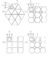
- FIG. 9 shows an example of the arrangement of the power generation members of the present invention, where (a) is a combination of triangular shapes, (b) is a combination of rectangular shapes, and (c) is a hexagonal shape. (D) is a schematic diagram of a combination of an octagonal shape and a quadrangular shape.
- the holding member 5, the piezoelectric element 2 and the pressing member 3 are shown only in the upper left power generation member 1 in each of the schematic diagrams (a) to (d), and the description of the others is omitted.
- the shape of the power generation member 1 of the present invention is preferably triangular, quadrangular, hexagonal, or octagonal in plan view.
- the shape of the power generation member 1 according to the present invention in plan view corresponds to the shape of the holding member 5 that is the portion having the largest outer shape when viewed in plan in the example illustrated in FIG. 9.
- the electrode 2c is a plate-like electrode and the electrode 2c has a function of holding the piezoelectric ceramic 2b on which the electrode 2a is formed, like the power generation member 1 shown in FIG. 1 or FIG. This corresponds to the shape of the electrode 2c.
- the shape of the power generation member 1 may be a triangular combination or a quadrangular combination when viewed in plan, or FIGS. 9C and 9D. If the shape of the power generation member 1 is a combination of a hexagonal shape and a triangular shape or a combination of an octagonal shape and a quadrangular shape in plan view, as shown in the schematic diagram of FIG. Since a plurality of power generating members 1 can be arranged closely in a plane in a state where there is almost no space, high power can be obtained efficiently.
- the pressing member 3 is a material having a hardness lower than that of the support member 4. If the pressing member 3 is a material whose hardness is lower than that of the support member 4, a large pressure or vibration energy is generated in the power generation member 1 due to a large pressure energy generated when a person walks or a large vibration energy generated when a car or the like travels. Even if it is applied, the pressing member 3 absorbs and relaxes a large pressure or vibration energy, and the supporting member 4 can support the piezoelectric element 2 by suppressing excessive deformation of the piezoelectric element 2. It is possible to suppress the ceramic 2b from cracking.
- the pressing member 3 is made of at least one selected from rubber, resin, carbon nanotube and carbon fiber material
- the supporting member 4 is austenitic stainless steel such as SUS303, SUS304, SUS316, 3000 series, 5000 series.
- a combination of at least one selected from metals such as aluminum alloys is preferred.
- the difference in hardness according to ISO 7619-2004 between the pressing member 3 and the supporting member 4 is preferably A5 / 15 / S or more. It is.
- the piezoelectric ceramic 2b is preferably made of lead zirconate titanate. This is because lead zirconate titanate has high ferroelectricity, which is one of the characteristics affecting the amount of power generation, and higher power can be obtained when the piezoelectric ceramic 2b is made of lead zirconate titanate.
- the composition formula is represented by PbZrO 3 —PbTiO 3 —Pb (Zn 1/3 Sb 2/3 ) O 3 .
- the main component is bismuth (Bi) and iron (Fe) in terms of BiFeO 3 in a range of 5% by mass to 15% by mass, another example being a composition formula of Pb 1-x- y Sr x Ba y is represented by (Zn 1/3 Sb 2/3) a ( Ni 1/2 Te 1/2) b Zr c Ti 1-a-b-c O 3, x, y, a, b , C have a molar ratio of 0 ⁇ x ⁇ 0.12, 0 ⁇ y ⁇ 0.12, 0 ⁇ x + y, 0.05 ⁇ a ⁇ 0.12, 0 ⁇ b ⁇ 0.015 and 0.43 ⁇ c ⁇ 0.52 to 100 parts by weight of the component which satisfies consists equimolar ratio PbO and Nb
- the O 5 to 0.2-1.2 parts by weight containing principal component comprising a total of ceramics containing magnesium (Mg) in a range of less than 0.6 mol%
- a material piezoelectric constant d 33 is large, as an example, a composition formula Pb 1-x-y Sr x Ba y (Zn 1/3 Sb 2/3) a Zr b Ti 1-a-b
- the molar ratio represented by O 3 and represented by x, y, a, b is 0 ⁇ x ⁇ 0.14, 0 ⁇ y ⁇ 0.14, 0.04 ⁇ x + y, 0.01 ⁇ a ⁇ 0.12, and It is preferable that the ceramic satisfies 0.43 ⁇ b ⁇ 0.58.
- x, y, a, the molar ratio shown in b is in this range, the can be given by repeated load extremely small attenuation factor of the piezoelectric constant d 33.
- the piezoelectric ceramic 2b is preferably composed of potassium niobate, sodium, and lithium as main components, and calcium titanate and bismuth ferrate.
- Piezoelectric ceramic 2b is a main component of potassium sodium-lithium niobate, when containing calcium titanate and bismuth ferrite, the resonance frequency in the temperature range of -40 ⁇ + 0.99 ° C., the temperature of the anti-resonance frequency and piezoelectric constant g 33
- a discontinuous portion called a second-order phase transition caused by phase change from a low-temperature ferroelectric phase to a high-temperature ferroelectric phase is less likely to occur due to the rate of change, so that the piezoelectric characteristics can be stabilized.
- the main component in the piezoelectric ceramic 2b is a component that occupies 50% by mass or more out of 100% by mass of all the components constituting the piezoelectric ceramic 2b.
- FIG. 10 shows an example of an embodiment of a power generation device using the power generation member of the present invention
- (a) is a perspective view
- (b) is an enlarged view of a V portion in (a)
- (c ) Is a cross-sectional view taken along line JJ ′ in FIG.
- each pressing member 3 is held by a plate-like first cover member 7, and each support member 4 is a plate.
- the second cover member 8 is held in a shape.
- the pressing member 3 and the support member 4 are preferably held or joined to the first cover member 7 and the second cover member 8 by using a joining member such as an adhesive or a screw, respectively.
- the pressing member 3 and the support member 4 are held by the first cover member 7 and the second cover member 8, and a plurality of power generation members 1 of the present invention having high power generation are provided.
- a plurality of power generation members 1 of the present invention having high power generation are provided.
- the pressing member 3 and the support member 4 are held by the first cover member 7 and the second cover member 8, respectively, and vibration energy is not transmitted to the specific power generation member 1, but is distributed to the plurality of power generation members 1. Therefore, the power generation member 1 is less likely to be damaged and can be used for a long period of time.
- the power generation member 1 of the present invention constituting the power generation device 6 of the present invention has a triangular shape, a quadrangular shape, a hexagonal shape, or an octagonal shape when viewed in plan
- a plurality of power generation members 1 are formed by combining them.
- the power generation device 6 composed of a plurality of power generation members 1 can also have various shapes such as a triangular shape, a quadrangular shape, a hexagonal shape, and an octagonal shape in plan view. They can be arranged closely in a plane.
- FIG. 11 shows another example of the embodiment of the power generation device using the power generation member of the present invention, (a) is a perspective view, (b) is an enlarged view of the W portion in (a), (C) is a sectional view taken along line KK ′ in (b).
- the power generation device 6 of the example shown in FIG. 11 has a quadrangular shape in plan view, such as the pressing member 3 and the piezoelectric element 2 constituting the power generation member 1, and a plurality of the power generation members 1 are arranged closely in a plane.
- each pressing member 3 is held by a plate-like first cover member 7, and each support member 4 is held by a plate-like second cover member 8.
- the first and second cover members 7 and 8 have a quadrangular shape in plan view, but the shape of the power generation member 1 in plan view is triangular, quadrangular, hexagonal, octagonal, or a combination thereof. By doing so, it is possible to arrange a plurality of power generation members 1 in a state where there is almost no wasted space between the power generation members 1, so that high power can be obtained efficiently,
- the power generation device 6 can have various shapes.
- FIG. 12 shows another example of the embodiment of the power generation device using the power generation member of the present invention, (a) is a perspective view, (b) is an enlarged view of a portion X in (a), (C) is a sectional view taken along line LL ′ in (b).
- the pressing member 3 is formed integrally with the first cover member 7, and the pressing member 3 and the first cover member 7 are not simply in contact but integrated. Since it is formed, the relative positional relationship between the piezoelectric element 2 and the pressing member 3 does not change.
- power generation using pressure energy generated when a person walks or vibration energy generated when a vehicle or the like travels. Even if the process is repeated, the adhesion is not peeled off and the coupling member such as a screw is not loosened, so that high power can be efficiently obtained over a long period of time.
- FIG. 13 shows another example of the embodiment of the power generation device using the power generation member of the present invention, (a) is a perspective view, (b) is an enlarged view of the Y part in (a), (C) is a sectional view taken along line MM ′ in (b).
- the support member 4 is formed integrally with the second cover member 8, and the support member 4 and the second cover member 8 are not simply in contact but integrated with each other. Since it is formed, the relative positional relationship between the piezoelectric element 2 and the support member 4 does not change. Further, compared with the case where the support member 4 and the first cover member 7 are joined or coupled, power generation using pressure energy generated when a person walks or vibration energy generated when a vehicle or the like travels. Even if the process is repeated, the adhesion is not peeled off and the coupling member such as a screw is not loosened, so that high power can be efficiently obtained over a long period of time. Furthermore, since the support member 4 and the second cover member 8 are integrally formed, the joining or joining process can be reduced.
- the power generation device 6 includes the pressing member 3 formed integrally with the first cover member 7, the support member 4 formed integrally with the second cover member 8, and the piezoelectric element 2, A similar effect can be obtained, which is preferable. Furthermore, in the example shown in FIGS. 12 and 13, the first cover member 7 and the second cover member 8 formed integrally with the individual pressing members 3 and the support members 4 are shown. It is also preferable to form it integrally with the support member 4.
- 14 and 15 are schematic configuration diagrams showing an example of an embodiment of a power generation system using the power generation device of the present invention.
- the power generation system 9 of the example shown in FIGS. 14 and 15 is a power generation system including the power generation device 6 of the present invention and a DC / AC conversion device 12 connected via a circuit including diodes 10 a and 10 b and a capacitor 11.
- 14 shows that the pressing member 3 of the power generation member 1 constituting the power generation device 6 of the present invention has a flat pressing surface
- FIG. 15 has an annular pressing surface. The pressing member 3 is shown.
- the pressing member 3 having a flat pressing surface held by the first cover member 7 by the energy of pressure generated when a person walks or the vibration energy generated when a vehicle or the like travels.
- the pressing member 3 having an annular pressing surface presses the piezoelectric element 2, and the supporting member 4 held by the second cover member 8 supports the peripheral portion of the piezoelectric element 2, so that the piezoelectric ceramic 2 b is distorted.
- the voltage generated by this distortion is accumulated as a charge in the capacitor 11 through the diode 10a.
- condenser 11 can be taken out through the diode 10b, can be converted into an alternating current with the direct current alternating current converter 12, and can be taken out as electric power.
- the electric power generation system 9 of this invention by which the electric power generating apparatus 6 of this invention is arrange
- the power generation device 6 of the present invention provided in the power generation system 9 of the present invention has a shape between the power generation devices 6 as long as the shape of the power generation device 6 in a plan view is a triangle shape, a quadrangular shape, a hexagonal shape, or an octagonal shape. Since a plurality of power generators 6 can be arranged closely in a plane in a state where there is almost no wasted space, high power can be obtained efficiently. Furthermore, it is possible to make the power generation system 9 excellent in decorativeness by changing the color of the first cover member 7 or combining the power generation devices 6 having various shapes.
- the piezoelectric ceramic 2b is made of lead zirconate titanate
- lead oxide (Pb 3 O 4 ), zirconium oxide (ZrO 2 ), titanium oxide (TiO 2 ), strontium carbonate (SrCO 3 ), barium carbonate (BaCO 3 ), zinc oxide (ZnO), antimony oxide (Sb) 2 O 3 ), nickel oxide (NiO), and tellurium oxide (TeO 2 ) powders are weighed and mixed to prepare raw materials.
- the mixed raw materials are placed in a ball mill together with water as a solvent, and mixed and pulverized for 20 hours or more 30 A slurry is obtained by performing for less than an hour.
- balls containing zirconia as a main component may be used.
- lead oxide (PbO) and niobium oxide (Nb 2 O 5 ) may be weighed and mixed as needed.
- calcined powder is obtained by calcining in an air atmosphere at a temperature of 850 ° C. to 900 ° C. and a holding time of 1 hour to 3 hours.
- a predetermined amount of magnesium carbonate (MgCO 3 ) powder is added to the obtained calcined powder so that the magnesium (Mg) content is 0.6 mol% or less, and pulverized, mixed, and mixed.
- MgCO 3 magnesium carbonate
- a slurry is prepared from the mixed powder, and a molded body having a predetermined shape such as a disk, triangle, square, hexagon or octagon is obtained by a tape molding method or an extrusion molding method, or from the mixed powder.
- Granules may be produced from the produced slurry by a spray drying method, and a molded body having a predetermined shape may be formed by a dry pressure molding method. By firing this molded body at 1100 ° C. or higher and 1300 ° C. or lower in an air atmosphere or an oxygen atmosphere, a piezoelectric ceramic 2b which is a sintered body can be obtained.
- the obtained slurry is dehydrated and dried, and then calcined in an air atmosphere at a temperature of 850 ° C. or higher and 900 ° C. or lower and a holding time of 1 hour or longer and 3 hours or shorter, whereby the composition formula is PbZrO 3 ⁇
- a calcined powder mainly containing a component represented by PbTiO 3 —Pb (Zn 1/3 Sb 2/3 ) O 3 is obtained.
- a predetermined amount of each powder of bismuth oxide (Bi 2 O 3 ) and iron oxide (Fe 2 O 3 ) is added to the obtained calcined powder and mixed to obtain a mixed powder. From this mixed powder, a slurry is obtained.
- the piezoelectric ceramic 2b is composed mainly of potassium niobate / sodium / lithium and contains calcium titanate and bismuth ironate
- potassium carbonate (K 2 CO 3 ) sodium carbonate (Na 2 CO 3 ), lithium carbonate (Li 2 CO 3 ), calcium carbonate (CaCO 3 ), niobium oxide (Nb 2 O 5 ), titanium oxide (
- Each powder of TiO 2 ) and iron oxide (Fe 2 O 3 ) is weighed and mixed to prepare a raw material for preparation.
- the piezoelectric ceramic 2b for example, the composition formula is a (1-a-b) ( K x Na y Li 1-x-y) NbO 3 + aCaTiO 3 + bBiFeO 3, x, y, a, b, What is necessary is just to weigh so that the molar ratio of c satisfies 0 ⁇ a ⁇ 0.16, 0 ⁇ b ⁇ 0.1, 0 ⁇ x ⁇ 0.19, and 0.79 ⁇ y ⁇ 1.
- this blended raw material is put in a ball mill together with 2-propanol (isopropanol) as a solvent, and mixed and pulverized for 15 hours to 25 hours to obtain a slurry.
- 2-propanol isopropanol
- balls containing zirconia as a main component may be used.
- the obtained slurry is dehydrated and dried, it is calcined at 900 ° C. or higher and 1000 ° C. or lower for 3 hours in the air atmosphere to obtain a calcined powder. Thereafter, the calcined powder is pulverized again with a ball mill, and a binder such as polyvinyl alcohol (PVA) is added to the calcined powder to form a slurry, which is dried by a spray drying method to form granules.
- PVA polyvinyl alcohol
- the obtained granule is formed into a predetermined shape by a dry pressure molding method at a pressure of 200 MPa, and the obtained shaped body is degreased as necessary, and then, for example, 1000 ° C. in an air atmosphere.
- the piezoelectric ceramic 2b can be obtained by firing at 1250 ° C. or lower.
- a paste made of at least one selected from gold, silver, copper and palladium, for example, having high electrical conductivity is applied to one main surface of the piezoelectric ceramic 2b obtained by any of the above-described manufacturing methods by screen printing or dipping.
- the electrode 2a is formed by applying by a known method such as a method and applying heat treatment.
- a plate-like body made of brass is bonded to the other main surface of the piezoelectric ceramic 2b with an adhesive such as an epoxy adhesive to form the electrode 2c, and then in silicon oil having a temperature of 70 ° C. or higher and 90 ° C. or lower.
- a paste made of at least one selected from, for example, gold, silver, copper, and palladium, having high electrical conductivity is applied to both main surfaces of the piezoelectric ceramic 2b obtained by any one of the above-described manufacturing methods.
- the electrodes 2a and 2c are formed by applying by a known method such as the method, the electrodes 2a and 2c are formed and then in a silicon oil having a temperature of 70 ° C. or higher and 90 ° C. or lower in a range of 10 to 30 minutes and 3 kV / mm to 7 kV Polarization treatment may be performed by applying a DC electric field of / mm or less so that the electrode 2c is negative and the electrode 2a is positive.
- the piezoelectric element 2 shown in FIG. 3, FIG. 6, FIG. 7 or FIG. 8 is bonded to the holding member 5 made of brass having high electrical conductivity with an acrylic resin adhesive. Obtainable.
- the piezoelectric element 2 obtained by any of the above-mentioned methods, the supporting member 4 that supports the peripheral portion of the piezoelectric element 2, and the pressing member 3 that presses with a flat pressing surface inside the supporting member 4 or an annular shape
- the power generation member 1 of the present invention can be obtained by disposing the pressing member 3 pressed by the pressing surface at a predetermined position.
- each pressing member 3 is held by a plate-like first cover member 7
- each supporting member 4 is a plate-like second cover.
- the shape of the first and second cover members 7 and 8 in plan view is triangular, quadrangular, hexagonal or octagonal
- the shape in plan view is triangular, quadrangular, hexagonal or octagonal This can be dealt with by producing and combining the shape of the power generation member 1.
- the power generation system 9 of the present invention can be obtained by connecting the DC / AC converter 12 to the power generation apparatus 6 of the present invention via a circuit including the diodes 10a and 10b and the capacitor 11.
- layered electrodes 2a made of silver as a main component were formed on both main surfaces of a piezoelectric ceramic 2b made of disc-shaped lead zirconate titanate having a diameter of 25 mm and a thickness of 0.25 mm.
- a DC electric field of 5 kV / mm is applied for 30 minutes in 90 ° C. silicone oil, and polarization treatment is performed so that the electrode 2c becomes negative and the electrode 2a becomes positive.
- the diameter is 35 mm and the thickness is 0.
- a piezoelectric element 2 shown in FIG. 1 was formed by bonding an electrode 2c, which is a circular plate electrode made of 3 mm brass, using an acrylic resin adhesive.
- a pressing member for pressing one main surface side of the piezoelectric element 2 a pressing member having a spherical pressing surface and a pressing member 3 having a flat and annular pressing surface were prepared.
- a support member to be supported on the other main surface side of the piezoelectric element 2 a support member that supports the entire surface of the piezoelectric element 2 and a support member 4 that supports the periphery of the piezoelectric element 2 were prepared.
- a power generation member having a combination shown in Table 1 was produced by the piezoelectric element 2 and the prepared pressing member and support member, and a circuit was formed by connecting a resistance of 1 M ⁇ in parallel to the power generation member.
- the pressing member is attached to a precision universal testing machine (manufactured by Shimadzu Corporation, Autograph (registered trademark) AGS-J), presses the piezoelectric element 2 at a speed of 100 mm / min, and is applied to the piezoelectric element 2 every 0.05 seconds.
- the load was measured with this precision universal testing machine.
- the voltage between the resistors and the resistance value were detected with a digital electrometer (R8252 manufactured by Advantest) every 0.05 seconds.
- the amount of electric power in each time is calculated from the voltage and resistance value detected from when the load is applied to 40 N, the value obtained by adding the values is the total electric energy, and the pressing surface is planar.
- the support member supported on the other main surface side of the piezoelectric element 2 is a combination of support members that support the entire surface of the piezoelectric element 2.
- the relative value when the total power amount of 1 is 1 is shown. The results are shown in Table 1.
- the pressing surface of the pressing member is flat, and the sample No. 2 in which the supporting member supports the entire surface of the piezoelectric element 2 is obtained.
- the power generating member 1 could not sufficiently bend the piezoelectric ceramic 2b because the supporting member supported the entire surface of the piezoelectric element 2, and the total amount of electric power obtained with small distortion was small.
- the support member 4 supports the peripheral portion of the piezoelectric element 2, so Although it was able to bend more than 1, a negative strain was generated at the center of the pressed piezoelectric ceramic 2b, whereas the sign of the strain was reversed as it progressed in the radial direction from the center toward the outer periphery. A positive strain is generated on the outer periphery of the ceramic 2b, and the charge generated by the presence of the positive and negative strains is offset. The total power amount is 10 times that of 1.
- the pressing surface of the pressing member 3 is flat, and the support member 4 supports the peripheral portion of the piezoelectric element 2 Sample No. which is an embodiment of the present invention.
- the support member 4 supports the peripheral portion of the piezoelectric element 2 and the pressing member 3 presses the piezoelectric element 2 with a flat pressing surface inside the supporting member 4, the piezoelectric ceramic 2 b is sufficiently bent. Since the position where the sign of the strain is reversed is shifted to the outer peripheral side, the cancellation of the charges generated can be reduced. A total power amount 100 times that of 1 could be obtained.
- the supporting member 4 supports the peripheral portion of the piezoelectric element 2, and the pressing surface of the pressing member 3 that presses the piezoelectric element 2 inside the supporting member 4 is annular.
- the piezoelectric ceramic 2b is sufficiently bent and greatly distorted, and it is possible to reduce the cancellation of charges generated by shifting the position where the sign of the strain is reversed to the outer peripheral side. A total power amount 100 times that of 1 could be obtained.
- a piezoelectric element 2 shown in FIGS. 1 and 4 was produced in the same manner as in Example 1.
- the supporting member 4 that supports the periphery of the piezoelectric element 2 shown in FIG. 1 and the pressing member 3 that presses the piezoelectric element 2 with a flat pressing surface inside the supporting member 4 are made of materials having different hardnesses.
- the support member 4 that annularly supports the peripheral portion of the piezoelectric element 2 shown in FIG. 4 and the pressing member 3 that has an annular pressing surface that presses the piezoelectric element 2 inside the support member 4 are made of materials having different hardnesses. Made.
- the power generation member 1 having a combination shown in Table 2 is produced, and the thickness t from the electrode 2a to the electrode 2c shown in FIG. Measured with a dial gauge. Thereafter, a 1 M ⁇ resistor was connected in parallel to the power generation member 1 to form a circuit.
- the pressing member 3 is attached to a precision universal testing machine (Autograph (registered trademark) AGS-J, manufactured by Shimadzu Corporation), and the piezoelectric element 2 is pressed at a speed of 200 mm / min in order to apply a sudden load.
- the load applied to the piezoelectric element 2 every 0.05 seconds was measured with this precision universal testing machine.
- the voltage between the resistors and the resistance value were detected with a digital electrometer (R8252 manufactured by Advantest) every 0.05 seconds.
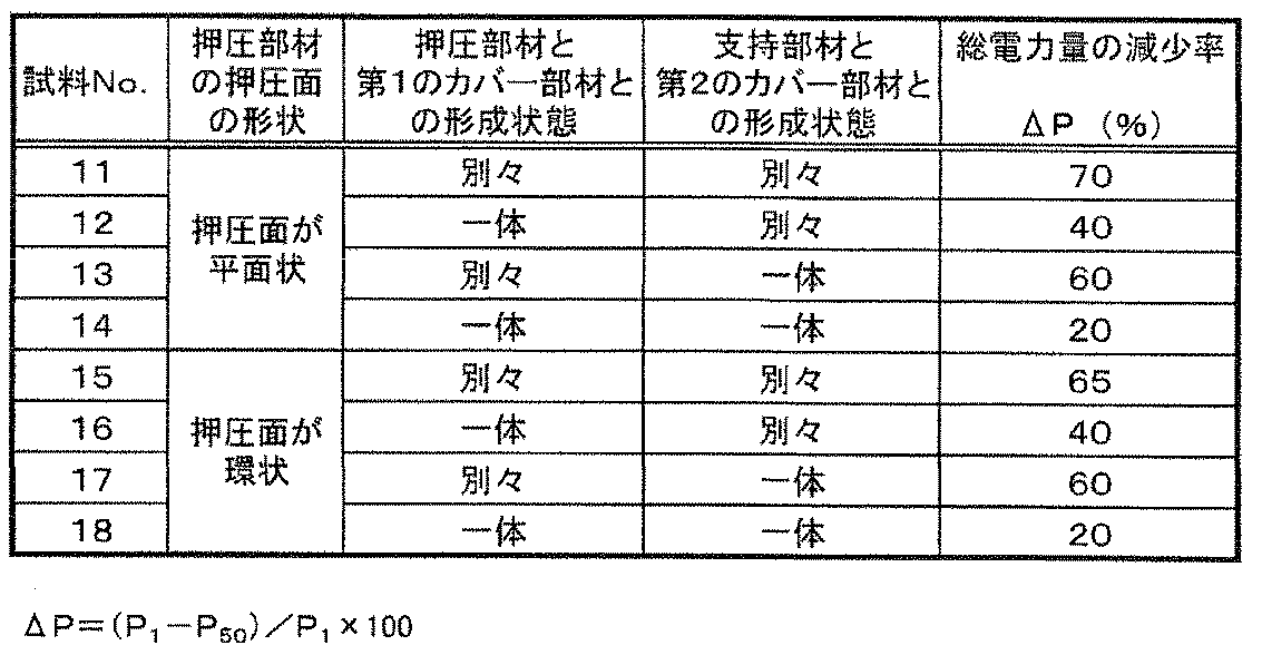
- the period from when the load is applied to 40N is taken as one cycle, the electric energy at each time is calculated from the voltage and the resistance value detected during the one cycle, and the total value is calculated as the total electric energy P. It was set to 1 .
- the measurement of the thickness t of the electrode 2a measured with a dial gauge to the electrode 2c before placing a load and t the measured value of the thickness t of from 50 cycles after the end of the electrode 2a to the electrode 2c t 50 .
- the hardness of the pressing member 3 is lower than the hardness Hs of the supporting member 4. 6 and 9, since the thickness increase rate ⁇ t and the total power decrease rate ⁇ P were very small, the pressing member 3 had a hardness lower than that of the support member 4, which caused a sudden load on the piezoelectric element 2. It was also found that the impact associated with this load was absorbed by the pressing member 3 and alleviated, and the support member 4 could be supported while suppressing excessive deformation.
- a piezoelectric element 2 shown in FIGS. 1 and 4 was produced in the same manner as in Example 1.
- a pressing member 3 that presses the piezoelectric element 2 with an annular pressing surface that presses the piezoelectric element 2 inside the support member 4 A first cover member 7 holding the pressing member 3 and a pressing member 3 formed integrally with the first cover member 7 were prepared.
- a support member 4 that supports the periphery of the piezoelectric element 2, a second cover member 8 that holds the support member 4, and a support member 4 that is formed integrally with the second cover member 8 were prepared. Then, using these members, power generation apparatuses 6 having combinations shown in Table 3 were produced, and a circuit was formed by connecting each power generation member 1 with a resistance of 10 M ⁇ in parallel.
- Table 3 shows that the pressing member 3 is bonded to the first cover member 7 and the support member 4 is bonded and held to the second cover member 8 as “separate”. Further, the pressing member 3 formed integrally with the first cover member 7 and the support member 4 formed integrally with the second cover member 8 are shown as “integrated” in Table 3.
- the piezoelectric element 2 is pressed at a speed of 100 mm / min through the first cover member 7 and the pressing member 3.
- the load applied to the piezoelectric element 2 was measured every 0.05 seconds.
- the voltage between the resistors and the resistance value were detected with a digital electrometer (R8252 manufactured by Advantest) every 0.05 seconds.
- the period from when the load is applied to 80 N is taken as one cycle, and the electric energy at each time is calculated from the voltage and resistance value detected during this one cycle. It was set to 1 .
- the sample No. 1 in which the pressing member 3 and the supporting member 4 are formed integrally with the first cover member 7 and the second cover member 8 is formed. 14 and 18, the reduction rate ⁇ P of the total electric energy is very small. From these results, the pressing member 3 presses the piezoelectric element 2 without being displaced, and the support member 4 supports the piezoelectric element 2 to improve the efficiency. In order to obtain electric power well, it has been found that the pressing member 3 and the supporting member 4 are preferably formed integrally with the first cover member 7 and the second cover member 8, respectively.
- a plurality of piezoelectric elements 2 having a circular shape, a triangular shape, a quadrangular shape, a hexagonal shape, and an octagonal shape in plan view were produced.
- a second cover member 8 in which a support member 4 for supporting the portion is integrally formed.
- the power generation member 1 having a circular shape, a triangular shape, a quadrangular shape, a hexagonal shape, and an octagonal shape in plan view is produced, and FIGS. 13 and 9A to 9D are used.
- a power generation device 6 was produced as an arrangement shown. In addition, it produced so that it might become equal about the area of the electric power generating apparatus 6, and connected the resistance of 10Mohm to each electric power generation member 1 in parallel, and formed the circuit.
- the sample No. 1 in which the shape of the power generation member 1 when viewed in plan is a circle is shown.
- the power generation member 1 having a triangular shape when viewed in plan is arranged as shown in FIG. 20
- a sample No. 1 in which the power generation member 1 having a square shape when viewed in plan is arranged as shown in FIG. 21.
- the power generation member 1 having a hexagonal shape and a triangular shape in plan view is arranged as shown in FIG. 22
- the power generation member 1 having an octagonal shape and a quadrangular shape when viewed in plan is arranged as shown in FIG.
- the total power amount of 23 was large.
- the shape of the power generation member 1 in plan view is triangular, quadrangular, hexagonal, or octagonal, a plurality of power generation members 1 are provided with almost no wasted space between the power generation members 1. It can be arranged closely in a plane shape, and the amount of power generation increases, which proves preferable.
Landscapes
- Engineering & Computer Science (AREA)
- Chemical & Material Sciences (AREA)
- Combustion & Propulsion (AREA)
- Physics & Mathematics (AREA)
- Electromagnetism (AREA)
- Mechanical Engineering (AREA)
- General Engineering & Computer Science (AREA)
- Architecture (AREA)
- Civil Engineering (AREA)
- Structural Engineering (AREA)
- General Electrical Machinery Utilizing Piezoelectricity, Electrostriction Or Magnetostriction (AREA)
Abstract
Description
2:圧電素子
2a:電極
2b:圧電セラミックス
2c:電極
3:押圧部材
4:支持部材
5:保持部材
6:発電装置
7:第1のカバー部材
8:第2のカバー部材
9:発電システム
10a,10b:ダイオード
11:コンデンサ
12:直流交流変換装置
図1は、本発明の発電部材の実施の形態の一例を示す、(a)は斜視図であり、(b)は(a)におけるA-A’線での断面図である。また、(c)は押圧部材によって圧電素子が押圧されている状態の断面図である。
なお、圧電セラミックス2bにおける主成分とは、圧電セラミックス2bを構成する全成分100質量%のうち、50質量%以上を占める成分である。
まず、圧電セラミックス2bがチタン酸ジルコン酸鉛からなる場合の例について説明する。出発原料として酸化鉛(Pb3O4),酸化ジルコニウム(ZrO2),酸化チタン(TiO2),炭酸ストロンチウム(SrCO3),炭酸バリウム(BaCO3),酸化亜鉛(ZnO),酸化アンチモン(Sb2O3),酸化ニッケル(NiO)および酸化テルル(TeO2)の各粉末を秤量混合して調合原料とし、この調合原料を溶媒である水とともにボールミルに入れて、混合粉砕を20時間以上30時間以下行なってスラリーを得る。なお、ボールミルの混合粉砕では、ジルコニアを主成分とするボールを用いればよい。また、出発原料には、必要に応じて上記出発原料に加え、酸化鉛(PbO)および酸化ニオブ(Nb2O5)を秤量混合して用いてもよい。



Claims (11)
- 板状の圧電セラミックスの両主面に電極が形成された圧電素子と、該圧電素子を一方主面側から押圧する押圧部材と、前記圧電素子を他方主面側で支持する支持部材とを備えてなる発電部材であって、前記支持部材は前記圧電素子の周辺部を支持し、前記押圧部材は前記圧電素子を前記支持部材の内側で平面状の押圧面により押圧することを特徴とする発電部材。
- 板状の圧電セラミックスの両主面に電極が形成された圧電素子と、該圧電素子を一方主面側から押圧する押圧部材と、前記圧電素子を他方主面側で支持する支持部材とを備えてなる発電部材であって、前記支持部材は前記圧電素子の周辺部を支持し、前記押圧部材は前記圧電素子を前記支持部材の内側で環状の押圧面により押圧することを特徴とする発電部材。
- 板状の圧電セラミックスの両主面に電極が形成された圧電素子と、該圧電素子を一方主面側から押圧する押圧部材と、前記圧電素子を他方主面側で支持する支持部材とを備えてなる発電部材であって、平面視した形状が三角形状,四角形状,六角形状または八角形状であることを特徴とする発電部材。
- 前記押圧部材は、前記支持部材より硬度が低い材料からなることを特徴とする請求項1乃至請求項3のいずれかに記載の発電部材。
- 前記圧電セラミックスは、チタン酸ジルコン酸鉛からなることを特徴とする請求項1乃至請求項4のいずれかに記載の発電部材。
- 前記圧電セラミックスは、ニオブ酸カリウム・ナトリウム・リチウムを主成分とし、チタン酸カルシウムおよび鉄酸ビスマスを含むことを特徴とする請求項1乃至請求項4のいずれかに記載の発電部材。
- 請求項1乃至請求項6のいずれかに記載の前記発電部材が複数個面状に並べて配置されて、それぞれの前記押圧部材が板状の第1のカバー部材により保持され、それぞれの前記支持部材が板状の第2のカバー部材により保持されていることを特徴とする発電装置。
- 前記押圧部材が前記第1のカバー部材と一体に形成されていることを特徴とする請求項7に記載の発電装置。
- 前記支持部材が前記第2のカバー部材と一体に形成されていることを特徴とする請求項7に記載の発電装置。
- 請求項7乃至請求項9のいずれかに記載の発電装置と、ダイオードおよびコンデンサを含む回路を介して接続された直流交流変換装置とを備えていることを特徴とする発電システム。
- 請求項7乃至請求項9のいずれかに記載の発電装置が床,階段,道路,橋,駐車場または線路の下側に配置されていることを特徴とする発電システム。
Priority Applications (2)
| Application Number | Priority Date | Filing Date | Title |
|---|---|---|---|
| EP09829161.0A EP2362096A4 (en) | 2008-11-28 | 2009-11-27 | ENERGY GENERATION ELEMENT, ENERGY GENERATION DEVICE THEREFOR AND ENERGY GENERATION SYSTEM |
| US13/131,577 US20110278989A1 (en) | 2008-11-28 | 2009-11-27 | Power Generation Member, Power Generation Device Using Same and Power Generation System. |
Applications Claiming Priority (4)
| Application Number | Priority Date | Filing Date | Title |
|---|---|---|---|
| JP2008-303935 | 2008-11-28 | ||
| JP2008303935 | 2008-11-28 | ||
| JP2009186532A JP5808518B2 (ja) | 2008-11-28 | 2009-08-11 | 発電部材およびこれを用いた発電装置ならびに発電システム |
| JP2009-186532 | 2009-08-11 |
Publications (1)
| Publication Number | Publication Date |
|---|---|
| WO2010061916A1 true WO2010061916A1 (ja) | 2010-06-03 |
Family
ID=42225786
Family Applications (1)
| Application Number | Title | Priority Date | Filing Date |
|---|---|---|---|
| PCT/JP2009/070036 Ceased WO2010061916A1 (ja) | 2008-11-28 | 2009-11-27 | 発電部材およびこれを用いた発電装置ならびに発電システム |
Country Status (5)
| Country | Link |
|---|---|
| US (1) | US20110278989A1 (ja) |
| EP (1) | EP2362096A4 (ja) |
| JP (1) | JP5808518B2 (ja) |
| KR (1) | KR20110112310A (ja) |
| WO (1) | WO2010061916A1 (ja) |
Cited By (11)
| Publication number | Priority date | Publication date | Assignee | Title |
|---|---|---|---|---|
| CN102158126A (zh) * | 2011-04-01 | 2011-08-17 | 浙江师范大学 | 基于中空压电换能器的灯具开关用发电装置 |
| CN103888022A (zh) * | 2014-02-26 | 2014-06-25 | 浙江大学 | 基于智能材料的新型能量采集轮胎装置及其方法 |
| CN105099271A (zh) * | 2015-09-02 | 2015-11-25 | 北京印刷学院 | 轴对称共振储能电磁变换城市地铁列车减震发电装置 |
| CN105656348A (zh) * | 2016-01-26 | 2016-06-08 | 金陵科技学院 | 一种高承载力道路标识发光供电装置 |
| CN106251685A (zh) * | 2016-08-16 | 2016-12-21 | 湖北民族学院 | 车位状态信息采集装置及系统 |
| CN106297318A (zh) * | 2016-10-11 | 2017-01-04 | 无锡华赛伟业传感信息科技有限公司 | 一种基于无线扩频通信的远距离地磁检测系统 |
| CN106655888A (zh) * | 2017-01-13 | 2017-05-10 | 合肥工业大学 | 一种基于压电发电的可拆卸式振荡减速警示装置 |
| CN107565851A (zh) * | 2017-10-31 | 2018-01-09 | 长春工业大学 | 一种用于气动系统传感器供能的压电俘能装置 |
| JP2019009309A (ja) * | 2017-06-26 | 2019-01-17 | 京セラ株式会社 | 圧電型発電装置 |
| CN109286336A (zh) * | 2018-12-06 | 2019-01-29 | 安徽盛德能源互联网研究院有限公司 | 一种基于压电效应技术的发电嵌板 |
| CN110176875A (zh) * | 2019-06-25 | 2019-08-27 | 上海工程技术大学 | 一种压电式振动能量采集转换装置 |
Families Citing this family (25)
| Publication number | Priority date | Publication date | Assignee | Title |
|---|---|---|---|---|
| EP2425068B1 (en) * | 2009-04-27 | 2015-06-03 | Mohawk Carpet Corporation | Flooring systems and methods of using same |
| JP5672443B2 (ja) * | 2010-11-10 | 2015-02-18 | セイコーエプソン株式会社 | 液体噴射ヘッド、液体噴射装置、圧電素子及び圧電素子の製造方法 |
| JP5720038B2 (ja) * | 2010-11-29 | 2015-05-20 | 独立行政法人科学技術振興機構 | ハイブリッド発電素子 |
| JP5827806B2 (ja) * | 2011-01-26 | 2015-12-02 | 日本信号株式会社 | 駐車場の安全システム |
| JP5808558B2 (ja) | 2011-03-31 | 2015-11-10 | 株式会社eスター | 振動発電装置 |
| KR101534410B1 (ko) * | 2013-06-13 | 2015-07-09 | 한양대학교 산학협력단 | 압전 발전 장치 |
| JP6343144B2 (ja) * | 2013-12-20 | 2018-06-13 | Jr東日本コンサルタンツ株式会社 | 床発電構造 |
| KR101582281B1 (ko) * | 2014-02-04 | 2016-01-04 | 한국세라믹기술원 | 진동체 표면 부착형 압전 에너지 하베스팅 장치 및 이를 이용한 자가 발전식 센싱 장치 |
| WO2015183220A1 (en) * | 2014-05-30 | 2015-12-03 | Ergi̇n Erhan | Energy generation module used in machines operating with pressing force |
| CN104038103A (zh) * | 2014-06-30 | 2014-09-10 | 蒋德昌 | 一种台阶发电装置 |
| KR101682911B1 (ko) * | 2014-09-29 | 2016-12-07 | 한국세라믹기술원 | 발전 장치 및 이를 이용한 자가 발전식 센싱 장치 |
| CN104539192B (zh) * | 2014-12-22 | 2016-10-12 | 清华大学 | 一种压电式路面振动能量收集系统 |
| KR101659283B1 (ko) * | 2015-01-09 | 2016-09-23 | (주)아이블포토닉스 | 전기 에너지 발생 장치 |
| WO2016111601A1 (ko) * | 2015-01-09 | 2016-07-14 | (주)아이블포토닉스 | 전기 에너지 발생 장치 |
| CN104953894B (zh) * | 2015-07-02 | 2017-08-18 | 广西大学 | 压力发电摇摆木马 |
| GB2540588A (en) * | 2015-07-22 | 2017-01-25 | Altro Ltd | Improvements in or relating to floor coverings |
| CN105099270A (zh) * | 2015-09-02 | 2015-11-25 | 北京印刷学院 | 轴对称气动阻尼共振压电变换城市地铁列车减震发电装置 |
| GB2542203B (en) * | 2015-09-14 | 2018-01-17 | Pavegen Systems Ltd | Flooring system |
| CN105871250B (zh) * | 2016-04-11 | 2017-09-12 | 西安交通大学 | 利用载荷变化和往复重叠式压电薄膜的发电装置 |
| CN106230312B (zh) * | 2016-08-30 | 2018-09-25 | 长安大学 | 一种基于提高力电效应的道路机械能量收集装置 |
| GB201618486D0 (en) * | 2016-11-02 | 2016-12-14 | Johnson Electric Sa | Improvements in or relating to energy generation |
| CN106849751A (zh) * | 2017-03-01 | 2017-06-13 | 西北工业大学 | 一种运动自行车发电蓄电装置 |
| CN107592032B (zh) * | 2017-10-31 | 2019-09-10 | 长春工业大学 | 一种用于高压管道的活塞式磁力升频压电俘能器 |
| EP3544172A1 (en) * | 2018-03-23 | 2019-09-25 | Nederlandse Organisatie voor toegepast- natuurwetenschappelijk onderzoek TNO | Piezoelectric energy harvesting system |
| CN109104121B (zh) * | 2018-08-30 | 2019-09-10 | 长安大学 | 一种柔性压电发电路面减速带 |
Citations (9)
| Publication number | Priority date | Publication date | Assignee | Title |
|---|---|---|---|---|
| JPH01153913A (ja) | 1987-12-11 | 1989-06-16 | Nkk Corp | 燃焼炉の排ガス流量測定装置 |
| JPH0353913A (ja) | 1989-07-21 | 1991-03-07 | Sumitomo Wiring Syst Ltd | 防水コネクタハウジングの製造方法 |
| JPH0539661A (ja) | 1991-08-07 | 1993-02-19 | Y & Y:Kk | 発電機能を有する建築用床板素材 |
| JP2006158111A (ja) * | 2004-11-30 | 2006-06-15 | Matsushita Electric Works Ltd | 圧電型発電素子及び圧電型発電素子を利用したワイヤレススイッチ |
| JP2006197704A (ja) | 2005-01-13 | 2006-07-27 | Jr Higashi Nippon Consultants Kk | 発電システム |
| JP2007166881A (ja) * | 2005-12-19 | 2007-06-28 | Taiheiyo Cement Corp | 発電装置 |
| JP2007294593A (ja) * | 2006-04-24 | 2007-11-08 | Hitachi Cable Ltd | 圧電薄膜を用いた素子 |
| JP2008054450A (ja) * | 2006-08-25 | 2008-03-06 | Murata Mfg Co Ltd | 圧電発電装置 |
| JP2008211095A (ja) * | 2007-02-27 | 2008-09-11 | National Institute Of Advanced Industrial & Technology | 圧電素子、その製造方法およびそれを備えた発電装置 |
Family Cites Families (6)
| Publication number | Priority date | Publication date | Assignee | Title |
|---|---|---|---|---|
| DE10155125B4 (de) * | 2001-11-09 | 2004-07-15 | Enocean Gmbh | Vorrichtung zum Wandeln mechanischer Energie in elektrische Energie |
| EP1803168A4 (en) * | 2004-10-21 | 2009-05-20 | Michelin Soc Tech | MINIATURIZED PIEZOELECTRICALLY BASED VIBRATION ENERGY COLLECTION DEVICE |
| JP3768520B1 (ja) * | 2005-04-13 | 2006-04-19 | 太平洋セメント株式会社 | 発電装置 |
| JP4726672B2 (ja) * | 2006-03-28 | 2011-07-20 | 京セラ株式会社 | 圧電磁器 |
| JP2008098483A (ja) * | 2006-10-13 | 2008-04-24 | Taiheiyo Cement Corp | 圧電素子 |
| US20090195124A1 (en) * | 2008-02-06 | 2009-08-06 | Innowattech Ltd. | Energy harvesting from airport runway |
-
2009
- 2009-08-11 JP JP2009186532A patent/JP5808518B2/ja active Active
- 2009-11-27 US US13/131,577 patent/US20110278989A1/en not_active Abandoned
- 2009-11-27 EP EP09829161.0A patent/EP2362096A4/en not_active Withdrawn
- 2009-11-27 KR KR20117014795A patent/KR20110112310A/ko not_active Withdrawn
- 2009-11-27 WO PCT/JP2009/070036 patent/WO2010061916A1/ja not_active Ceased
Patent Citations (9)
| Publication number | Priority date | Publication date | Assignee | Title |
|---|---|---|---|---|
| JPH01153913A (ja) | 1987-12-11 | 1989-06-16 | Nkk Corp | 燃焼炉の排ガス流量測定装置 |
| JPH0353913A (ja) | 1989-07-21 | 1991-03-07 | Sumitomo Wiring Syst Ltd | 防水コネクタハウジングの製造方法 |
| JPH0539661A (ja) | 1991-08-07 | 1993-02-19 | Y & Y:Kk | 発電機能を有する建築用床板素材 |
| JP2006158111A (ja) * | 2004-11-30 | 2006-06-15 | Matsushita Electric Works Ltd | 圧電型発電素子及び圧電型発電素子を利用したワイヤレススイッチ |
| JP2006197704A (ja) | 2005-01-13 | 2006-07-27 | Jr Higashi Nippon Consultants Kk | 発電システム |
| JP2007166881A (ja) * | 2005-12-19 | 2007-06-28 | Taiheiyo Cement Corp | 発電装置 |
| JP2007294593A (ja) * | 2006-04-24 | 2007-11-08 | Hitachi Cable Ltd | 圧電薄膜を用いた素子 |
| JP2008054450A (ja) * | 2006-08-25 | 2008-03-06 | Murata Mfg Co Ltd | 圧電発電装置 |
| JP2008211095A (ja) * | 2007-02-27 | 2008-09-11 | National Institute Of Advanced Industrial & Technology | 圧電素子、その製造方法およびそれを備えた発電装置 |
Cited By (13)
| Publication number | Priority date | Publication date | Assignee | Title |
|---|---|---|---|---|
| CN102158126A (zh) * | 2011-04-01 | 2011-08-17 | 浙江师范大学 | 基于中空压电换能器的灯具开关用发电装置 |
| CN103888022A (zh) * | 2014-02-26 | 2014-06-25 | 浙江大学 | 基于智能材料的新型能量采集轮胎装置及其方法 |
| CN103888022B (zh) * | 2014-02-26 | 2016-08-17 | 浙江大学 | 基于智能材料的能量采集轮胎装置及其方法 |
| CN105099271A (zh) * | 2015-09-02 | 2015-11-25 | 北京印刷学院 | 轴对称共振储能电磁变换城市地铁列车减震发电装置 |
| CN105656348B (zh) * | 2016-01-26 | 2017-05-31 | 金陵科技学院 | 一种高承载力道路标识发光供电装置 |
| CN105656348A (zh) * | 2016-01-26 | 2016-06-08 | 金陵科技学院 | 一种高承载力道路标识发光供电装置 |
| CN106251685A (zh) * | 2016-08-16 | 2016-12-21 | 湖北民族学院 | 车位状态信息采集装置及系统 |
| CN106297318A (zh) * | 2016-10-11 | 2017-01-04 | 无锡华赛伟业传感信息科技有限公司 | 一种基于无线扩频通信的远距离地磁检测系统 |
| CN106655888A (zh) * | 2017-01-13 | 2017-05-10 | 合肥工业大学 | 一种基于压电发电的可拆卸式振荡减速警示装置 |
| JP2019009309A (ja) * | 2017-06-26 | 2019-01-17 | 京セラ株式会社 | 圧電型発電装置 |
| CN107565851A (zh) * | 2017-10-31 | 2018-01-09 | 长春工业大学 | 一种用于气动系统传感器供能的压电俘能装置 |
| CN109286336A (zh) * | 2018-12-06 | 2019-01-29 | 安徽盛德能源互联网研究院有限公司 | 一种基于压电效应技术的发电嵌板 |
| CN110176875A (zh) * | 2019-06-25 | 2019-08-27 | 上海工程技术大学 | 一种压电式振动能量采集转换装置 |
Also Published As
| Publication number | Publication date |
|---|---|
| EP2362096A4 (en) | 2013-10-16 |
| EP2362096A1 (en) | 2011-08-31 |
| JP5808518B2 (ja) | 2015-11-10 |
| JP2010153777A (ja) | 2010-07-08 |
| KR20110112310A (ko) | 2011-10-12 |
| US20110278989A1 (en) | 2011-11-17 |
Similar Documents
| Publication | Publication Date | Title |
|---|---|---|
| JP5808518B2 (ja) | 発電部材およびこれを用いた発電装置ならびに発電システム | |
| EP1100189A1 (en) | Piezoelectric generating apparatus | |
| Choi et al. | Relation between piezoelectric properties of ceramics and output power density of energy harvester | |
| US20120119621A1 (en) | Bending device for bending a piezoelectric bender, piezoelectric converter for converting mechanical energy into electrical energy, by using the bending device, and method for converting mechanical energy into electrical energy | |
| JP5520239B2 (ja) | 発電デバイスおよびそれを用いた発電モジュール | |
| JP2010103987A (ja) | 振動体 | |
| US20190019940A1 (en) | Piezoelectric element, vibrator, vibration wave motor, optical apparatus, and electronic apparatus | |
| JP2012164917A (ja) | 静電容量変化型発電素子 | |
| US10243135B2 (en) | Piezoelectric device and method for manufacturing piezoelectric device | |
| KR19990072689A (ko) | 압전세라믹및압전장치 | |
| JP5479027B2 (ja) | 発電部材およびこれを用いた発電装置 | |
| JP2012164727A (ja) | 静電容量変化型発電素子 | |
| CN108141152B (zh) | 电力生成设备及生成方法 | |
| KR20100090432A (ko) | 압전자성복합체를 이용한 무선 자가발전 충전장치 | |
| Lee et al. | Relationship between piezoelectric properties of ceramics and output performance of 33-mode piezoelectric energy harvesters | |
| WO2017145530A1 (ja) | 圧電デバイス | |
| SG185883A1 (en) | A self-powered remote control device | |
| JP4676286B2 (ja) | 単板型圧電バイモルフ素子の製造方法 | |
| EP4611248A1 (en) | Vibration actuator, optical device, and electronic device | |
| JP3803207B2 (ja) | 圧電磁器組成物及び圧電トランス | |
| Rjafallah et al. | Flexible bridge transducer based on the lead zirconate titanate/polyurethane composite | |
| JP2000275114A (ja) | センサ | |
| JP2001165785A (ja) | 圧力センサおよびその製造方法 | |
| KR200261123Y1 (ko) | 압전세라믹을 이용한 자력충전지 | |
| JPH05175568A (ja) | 圧電バイモルフの製造法 |
Legal Events
| Date | Code | Title | Description |
|---|---|---|---|
| 121 | Ep: the epo has been informed by wipo that ep was designated in this application |
Ref document number: 09829161 Country of ref document: EP Kind code of ref document: A1 |
|
| NENP | Non-entry into the national phase |
Ref country code: DE |
|
| WWE | Wipo information: entry into national phase |
Ref document number: 2009829161 Country of ref document: EP |
|
| ENP | Entry into the national phase |
Ref document number: 20117014795 Country of ref document: KR Kind code of ref document: A |
|
| WWE | Wipo information: entry into national phase |
Ref document number: 13131577 Country of ref document: US |