WO2010061948A1 - マルチビームアンテナ装置 - Google Patents
マルチビームアンテナ装置 Download PDFInfo
- Publication number
- WO2010061948A1 WO2010061948A1 PCT/JP2009/070108 JP2009070108W WO2010061948A1 WO 2010061948 A1 WO2010061948 A1 WO 2010061948A1 JP 2009070108 W JP2009070108 W JP 2009070108W WO 2010061948 A1 WO2010061948 A1 WO 2010061948A1
- Authority
- WO
- WIPO (PCT)
- Prior art keywords
- rotman lens
- antenna
- input terminal
- array antenna
- center line
- Prior art date
- Legal status (The legal status is an assumption and is not a legal conclusion. Google has not performed a legal analysis and makes no representation as to the accuracy of the status listed.)
- Ceased
Links
Images


Classifications
-
- H—ELECTRICITY
- H01—ELECTRIC ELEMENTS
- H01Q—ANTENNAS, i.e. RADIO AERIALS
- H01Q21/00—Antenna arrays or systems
- H01Q21/29—Combinations of different interacting antenna units for giving a desired directional characteristic
-
- H—ELECTRICITY
- H01—ELECTRIC ELEMENTS
- H01Q—ANTENNAS, i.e. RADIO AERIALS
- H01Q13/00—Waveguide horns or mouths; Slot antennas; Leaky-waveguide antennas; Equivalent structures causing radiation along the transmission path of a guided wave
- H01Q13/20—Non-resonant leaky-waveguide or transmission-line antennas; Equivalent structures causing radiation along the transmission path of a guided wave
- H01Q13/206—Microstrip transmission line antennas
-
- H—ELECTRICITY
- H01—ELECTRIC ELEMENTS
- H01Q—ANTENNAS, i.e. RADIO AERIALS
- H01Q19/00—Combinations of primary active antenna elements and units with secondary devices, e.g. with quasi-optical devices, for giving the antenna a desired directional characteristic
- H01Q19/06—Combinations of primary active antenna elements and units with secondary devices, e.g. with quasi-optical devices, for giving the antenna a desired directional characteristic using refracting or diffracting devices, e.g. lens
-
- H—ELECTRICITY
- H01—ELECTRIC ELEMENTS
- H01Q—ANTENNAS, i.e. RADIO AERIALS
- H01Q21/00—Antenna arrays or systems
- H01Q21/06—Arrays of individually energised antenna units similarly polarised and spaced apart
- H01Q21/061—Two dimensional planar arrays
- H01Q21/064—Two dimensional planar arrays using horn or slot aerials
-
- H—ELECTRICITY
- H01—ELECTRIC ELEMENTS
- H01Q—ANTENNAS, i.e. RADIO AERIALS
- H01Q21/00—Antenna arrays or systems
- H01Q21/06—Arrays of individually energised antenna units similarly polarised and spaced apart
- H01Q21/061—Two dimensional planar arrays
- H01Q21/065—Patch antenna array
-
- H—ELECTRICITY
- H01—ELECTRIC ELEMENTS
- H01Q—ANTENNAS, i.e. RADIO AERIALS
- H01Q25/00—Antennas or antenna systems providing at least two radiating patterns
- H01Q25/007—Antennas or antenna systems providing at least two radiating patterns using two or more primary active elements in the focal region of a focusing device
- H01Q25/008—Antennas or antenna systems providing at least two radiating patterns using two or more primary active elements in the focal region of a focusing device lens fed multibeam arrays
Definitions
- the present invention relates to a design method of a Rotman lens used in a multi-beam antenna device used for transmission and reception in a millimeter wave band.
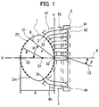
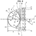
- FIG. 1 a plan view showing a conventional antenna device using a Rotman lens is shown in FIG.
- (1) is a Rotman lens
- (21), (22),..., (2 m) is an input terminal for supplying power to the Rotman lens (1), (31), (32),.
- ) Are output terminals for extracting power in the Rotman lens (1), (41), (42),..., (4n) are antenna elements for radiating radio waves into space
- (5) are a plurality of antenna elements (41 , (42), ... (4n) are arrayed linearly
- (61), (62), ... (6n) is a transmission line connecting the output terminal and the antenna element
- ( 7) is a line portion consisting of transmission lines (61), (62),...
- (8) is a center line, and this antenna device is opposed to the center line (8) Symmetry.
- (9) is an auxiliary line for representing the position of the input terminal (21), and the input terminal (21) is an elevation angle from the center line (8) when viewed from S2 which is the origin of the coordinate system (X, Y) It is in the direction of ⁇ .
- the input terminals (21), (22),... (2 m) are arranged on an arc of radius R centered on the Rotman lens focal point S1 position.
- S2 is indicated by the point of intersection of the partial curve on which the output terminals (31), (32),... (3n) are arranged and the center line (8), and is the origin of the coordinate system (X, Y).
- S3 indicates an intersection point of the center line (8) and the partial curve on which the input terminals (21), (22),... (2 m) are arranged.
- radius R is expressed by the following equation.
- G is the distance between S2 and S3 and is the size of the Rotman lens
- F is the distance between the input terminal (21) and S2
- 2Ln is the aperture length of the array antenna (5).
- ⁇ ⁇
- 0.8 ⁇ ⁇ 1 ie
- F is about 1 to 1.25 times Ln and g is about 1.137. 31), (32),..., (3n) can be designed small, and is considered good.
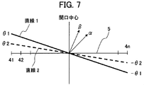
- the present invention when the beam forming direction of the array antenna (5) in space is ⁇ , the partial curve and the center line (8) at which the output terminals (31), (32),.
- the basics of designing the size G of the Rotman lens under the condition of ⁇ ⁇ under the condition of ⁇ ⁇ with respect to the angle ⁇ formed by the line connecting the intersection point S2 of S and the input terminal and the center line (8)
- the present invention provides a low-loss multi-beam antenna device that can be made smaller than a design size, thereby suppressing increase in loss of a Rotman lens and improving gain.
- the beam forming direction ⁇ of the array antenna (5) in space is the partial curve and the center where the output terminals (31), (32),.
- S3 Under the condition of ⁇ ⁇ with respect to the angle ⁇ between the line connecting the intersection point S2 of the line (8) and the input terminal and the center line (8), S3 has the input terminals (21), (22),.
- the Rotman lens is constituted by a triplate.
- the array antenna (5) is constituted by a triplate.
- the multi-beam antenna device is characterized in that the power is distributed and supplied with each input terminal section as a two-branch transmission line.
- a plurality of input terminals (21), (22),... (2 m) for supplying power and a plurality of output terminals for extracting power of the plurality of input terminals A Rotman lens formed of (31), (32),... (3 n), an array antenna composed of a plurality of antenna elements for radiating radio waves into space, a transmission connecting the output terminal and the antenna element A curved line on which a plurality of output terminals are arranged and a length of the transmission line are determined, and when a predetermined input terminal is excited, a beam is formed in an angular direction corresponding to the input terminal.
- the beam forming angle of the array antenna in space is ⁇ when viewed from the front of the array antenna, and the partial curve on which the output terminals (31), (32),... (3 n) are arranged and the Rotman lens Of the center line (8) of the Assuming that an angle formed by a line connecting one of the input terminals of the number and the center line (8) is ⁇ , ⁇ ⁇ , and S3 is input terminal (21), (22),.
- the shape of the Rotman lens is determined to be smaller than the size of.
- a plurality of input terminals (21), (22),... (2 m) for supplying power and a plurality of output terminals for extracting power of the plurality of input terminals A Rotman lens formed of (31), (32),... (3 n), an array antenna composed of a plurality of antenna elements for radiating radio waves into space, a transmission connecting the output terminal and the antenna element A curved line on which a plurality of output terminals are arranged and a length of the transmission line are determined, and when a predetermined input terminal is excited, a beam is formed in an angular direction corresponding to the input terminal.
- Rotman lens is Determining the number n of element rows of the input terminal or the output terminal; Determining an arrangement interval P of the element rows; Determining the number of beams and the beam step angle of the beams;
- the beam forming angle of the array antenna in space is ⁇ when viewed from the front of the array antenna, and the partial curve on which the output terminals (31), (32), ...
- the size G of the Rotman lens be the distance between S2 and S3.
- ⁇ ⁇ .
- a plurality of input terminals (21), (22),... (2 m) for supplying power and a plurality of output terminals for extracting power of the plurality of input terminals A Rotman lens formed of (31), (32),... (3 n), an array antenna composed of a plurality of antenna elements for radiating radio waves into space, a transmission connecting the output terminal and the antenna element A curved line on which a plurality of output terminals are arranged and a length of the transmission line are determined, and when a predetermined input terminal is excited, a beam is formed in an angular direction corresponding to the input terminal.
- the beam forming angle of the array antenna in space is ⁇ when viewed from the front of the array antenna, and the partial curve on which the output terminals (31), (32),... (3 n) are arranged and the Rotman lens Of the center line (8) of the
- the angle between the center line (8) as a alpha is a multi-beam antenna system for vehicle, characterized in that the beta ⁇ alpha.
- the beam forming direction ⁇ of the array antenna (5) in space is a partial curve on which the output terminals (31), (32),.
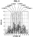
- composition of a multi beam antenna device concerning the present invention It is an explanatory view explaining composition of a multi beam antenna device concerning the present invention. It is an explanatory view which illustrates the composition of the multi beam antenna device concerning the present invention perspectively. It is an explanatory view explaining composition of an antenna substrate plane in a multi beam antenna device concerning the present invention. It is an explanatory view explaining composition of a Rotman lens substrate plane in a multi beam antenna device concerning the present invention. It is an explanatory view explaining a feed system of a Rotman lens input terminal in a multi beam antenna system concerning the present invention. It is an explanatory view explaining directivity characteristics of a multi beam antenna device concerning the present invention.
- the beam forming direction ⁇ of the array antenna (5) in space is a partial curve and a center line on which the output terminals (31), (32),.
- S3 has input terminals (21), (22),.
- the aperture center of the array antenna (5)
- a small Rotman lens with a size of ⁇ / ⁇ can be designed.
- the number of antenna elements (41), (42),... (4n) increases and the aperture 2Ln of the array antenna (5) becomes large.
- the transmission line portion 7 with a tapered shape or phase adjustment of complex input terminal portions and output terminal portions.
- the first connection portion (57) of the array antenna (5) can be formed through the first connection hole (59) provided in the first ground conductor (53).
- 58) and the connection terminal part (16) of the transmission line (7) can be electromagnetically coupled.
- the array antenna (5) also has a triplate configuration, whereby a low-loss multi-beam antenna device can be configured with a simple laminated configuration of all components.
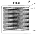
- the array antenna in the multi-beam antenna device includes the slot plate (50) shown in FIG. 2, the feed line (57) of the antenna substrate (52) and the first ground conductor (53).
- the array antenna of triplate configuration is formed, and by adopting this configuration, a low-loss multi-beam antenna device is configured with a simple lamination configuration of all parts. it can.
- the radiating element (56) formed on the antenna substrate (52) shown in FIG. 3 is the first ground conductor (53) and slot plate (50) shown in FIG.
- the slot (54) formed in the antenna serves as an antenna element and can emit radio waves of a desired frequency.
- an array antenna (5) is formed as a whole.
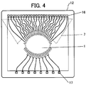
- the first ground conductor (53), the Rotman lens substrate (12), and the second ground conductor (13) shown in FIG. 2 form a Rotman lens of a triplate configuration. That is, more specifically, as shown in FIG. 2, the first ground conductor (53) and the transmission line portion (7) of the Rotman lens substrate (12) and the second ground conductor (13) are respectively By overlaying via the dielectrics (71a, 71b), a Rotman lens of triplate configuration is formed.
- the first connection portion (58) formed in the antenna substrate (52) is a Rotman lens substrate shown in FIG. 4 via the first connection hole (59) formed in the first ground conductor (53).
- the desired excitation power of the output terminal of the Rotman lens (1) is electromagnetically coupled to the connection terminal portion (16) of the transmission line (7) formed in (12) and transmitted to the array antenna (5).
- the metal spacers (51a, 51b) disposed above and below the antenna substrate (52) and the metal spacers (11a, 11b) disposed above and below the Rotman lens substrate (12) include the antenna substrate (52) and the Rotman Connection terminal of the first connection portion (58) formed on the antenna substrate (52) and the transmission line (7) formed on the rotoman lens substrate (12) while holding the lens substrate (12) hollow
- a metal wall is formed around the electromagnetic coupling portion of the part (16), which contributes to efficient transmission without leaking power to the surroundings, and low loss characteristics can be realized even at high frequencies.
- the space (55a, 55b) of the metal spacer (51a, 51b) and the space (14a, 14b) of the metal spacer (11a, 11b) stabilize the antenna substrate (52) and the Rotman lens substrate (12).
- a dielectric (71a, 71b) may be filled in order to hold it.
- the input terminal portion (17) of the antenna device has a metal wall formed by metal spacers (11a, 11b) around, and through the second connection hole (15) formed in the second ground conductor (13) This contributes to the efficient transfer to the high frequency circuit without leaking the power to the surroundings, and low loss characteristics can be realized even at high frequencies.
- the first connection hole (59) and the second connection hole (15) can be waveguide openings suitable for the use frequency band.
- the antenna substrate (52) and the Rotman lens substrate (12) used in the multi-beam antenna device according to the present invention use a flexible substrate obtained by bonding a copper foil to a polyimide film, and remove unnecessary copper foil by etching (56), feed line (57), first connection portion (58) and Rotman lens (1), transmission line (7), connection terminal portion (16) of transmission line (7), input terminal portion of antenna device It is preferable to form (17).
- a flexible substrate uses a film as a base material, and unnecessary copper foil (metal foil) of the substrate on which a metal foil such as copper foil is bonded is etched away to connect a plurality of radiation elements and power supply A track is formed.
- the flexible substrate may be a copper-clad laminate in which a thin resin plate in which a glass cloth is impregnated with a resin is laminated with a copper foil.
- a flexible substrate in which a copper foil is laminated on a polyimide film is preferable in terms of heat resistance, dielectric properties and versatility. Fluorine-based films are preferably used in view of dielectric properties.
- a metal plate or a plate plated with plastic can be used as the ground conductor or metal spacer used in the multi-beam antenna device according to the present invention, but in particular, using an aluminum plate is preferable because it is lightweight and inexpensive to manufacture.
- they can be constituted by a flexible substrate having a film as a base material and a copper foil laminated thereon, and a copper-clad laminate in which a copper foil is laminated to a thin resin plate having a resin impregnated with glass cloth.
- the slot and the joint formation portion formed in the ground conductor can be formed by punching using a mechanical press or etching. From the viewpoint of simplicity, productivity and the like, punching with a mechanical press is preferable.
- the substrate support dielectrics (71a, 71b) used in the multi-beam antenna device according to the present invention it is preferable to use a foam or the like having a small relative dielectric constant to air.
- the foam include polyolefin foams such as polyethylene and polypropylene, polystyrene foams, polyurethane foams, polysilicone foams, rubber foams, etc. It is preferable because the rate is smaller.
- the slot plate (50), the first ground conductor (53), the second ground conductor (13), the metal spacers (51a, 51b), and the metal spacers (11a, 11b) are made of an aluminum plate having a thickness of 0.3 mm.
- the substrate support dielectrics (71a, 71b) a foamed polyethylene foam having a thickness of 0.3 mm and a relative dielectric constant of about 1.1 was used.
- the antenna substrate (52) and the Rotman lens substrate (12) use a flexible substrate in which a copper foil (for example, 25 ⁇ m in thickness) is bonded to a polyimide film (for example, 25 ⁇ m in thickness) and removes unnecessary copper foil by etching.
- the ground conductor, the slot plate and the metal spacer were all aluminum plates punched out by a mechanical press.
- the antenna aperture 2Ln formed an array antenna (5) of 24 ⁇ 0.77 ⁇ o.
- a Rotman lens (1) having 24 output terminals was designed based on the coordinates and the electrical length w of the transmission line.
- the above-described members are sequentially stacked to form a multi-beam antenna device, and measuring devices are connected to measure characteristics.
- the reflection loss of each of the eight input terminals is -15 dB or less
- the insertion loss of (1) was about 5 dB.
- the relative gain is improved by 2.5 dB or more as compared with the case where the loss is configured in the conventional design, and good characteristics are realized.
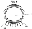
- Example 3 Furthermore, in the multi-beam antenna device according to the present invention, as shown in FIG. 5, the connection of the input terminals (521), (522),... , The power supplied to the interior of the Rotman lens (1) from each input terminal is concentrated at the center of the output terminals (531), (532),... (53 n), and the output terminal of the Rotman lens (1) By suppressing the diffusion of power to the area without the output terminals (531), (532),... The deterioration of the side lobe characteristic of the radiation beam of 5) can be suppressed.
- lens design based on the conventional Rotman lens design can be performed using the Rotman deformation method described above under the condition of ⁇ ⁇ . That is, in the condition of ⁇ ⁇ , since ⁇ (the radiation angle on the antenna element side) is smaller than ⁇ (the beam angle on the Rotman lens side), the present invention requires a high resolution for a narrow angle. Particularly effective.
- the range perpendicular to the front of the vehicle is 0 degrees, that is, the range up to about 15 degrees (that is, the opening angle up to about 30 degrees in total).
- the antenna device according to the present invention can obtain an ideal power distribution and phase distribution required for an on-vehicle antenna device and the like.
- Patent Document 3 A parallel plate having a plurality of input elements that can be individually excited and that supply power and a plurality of output elements that can extract the power; It consists of a plurality of element antennas, and consists of a transmission line connecting an array antenna that radiates radio waves into space, Based on three focal points on the curve on which the input elements are arranged, determine the length of the curve on which the output elements are arranged and the transmission line, In an antenna device in which a beam is emitted in an angular direction corresponding to an input element when a predetermined input element is excited, a shape of a curve in which the input element is arranged is not a part of a circle. Antenna device, It is.
- the antenna apparatus according to the present invention and the antenna apparatus described in Patent Document 3 have completely different configurations (lens shapes) and problems to be solved.
- Patent Document 4 describes a flat antenna for beam scanning which is excellent in thinning the antenna and simplifying the assembly process and can miniaturize the antenna.
- the connection portion 104 with the system, the Rotman lens portion 103, and the beam scanning antenna are described.
- a second ground conductor 13 a fourth dielectric 34, a Rotman lens pattern 8, a second connection portion 52, and a third connection portion 92.
- the present invention has been able to solve such problems, and to provide a low-loss multi-beam antenna device that enables Rotman lens design that suppresses loss increase and enables gain improvement.
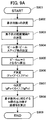
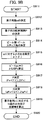
- the feature of the present invention is that the lens design based on the conventional Rotman lens design is made possible by using the Rotman deformation method under the condition of ⁇ ⁇ , but the Rotman deformation method according to the present invention is shown in FIG. This will be described in more detail based on the flowchart shown in FIG. 9B.
- FIG. 9A is a design flow based on the conventional Rotman method.
- the process advances to S902 to set the number n of antenna element rows.
- step S903 the arrangement interval P of n antenna element arrays is set.
- the antenna aperture 2Ln (n-1) P.
- step S904 the number of beams and the beam step angle are set.
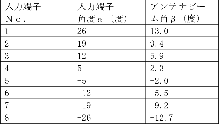
- the number of beams is the number of input terminals.
- the angular difference between the antenna beam angles ⁇ relative to (eg, in Table 1, the beam step angle is approximately 4 degrees).
- the distance F between the input terminal (21) and S2 is determined.
- it is set in the range of F 0 ⁇ F ⁇ 1.25F 0.
- the lens size G is determined.
- a gF 0 ⁇ G ⁇ 1.25gF 0. That is, when the shape factor g G / F is set to the general value 1.136, 1.136F 0 ⁇ G ⁇ 1.4F 0 It becomes.
- FIG. 9B is a design flow based on the Rotman deformation method according to the present invention.
- the difference from FIG. 9A is that the ratio of ⁇ to ⁇ can be set in S915, but at this time, a ratio can be set such that ⁇ > ⁇ .
- This setting is used as a coefficient for ⁇ , as shown in Equation 6. That is, Each design parameter is controlled so that the shape of the Rotman lens is determined so as to satisfy the relational expression, and the terminal coordinates (X, Y) are calculated.
- the distance F between the input terminal (21) and S2 is determined.
- it is set in the range of F X ⁇ F ⁇ 1.25F X.
- the lens size G is determined.
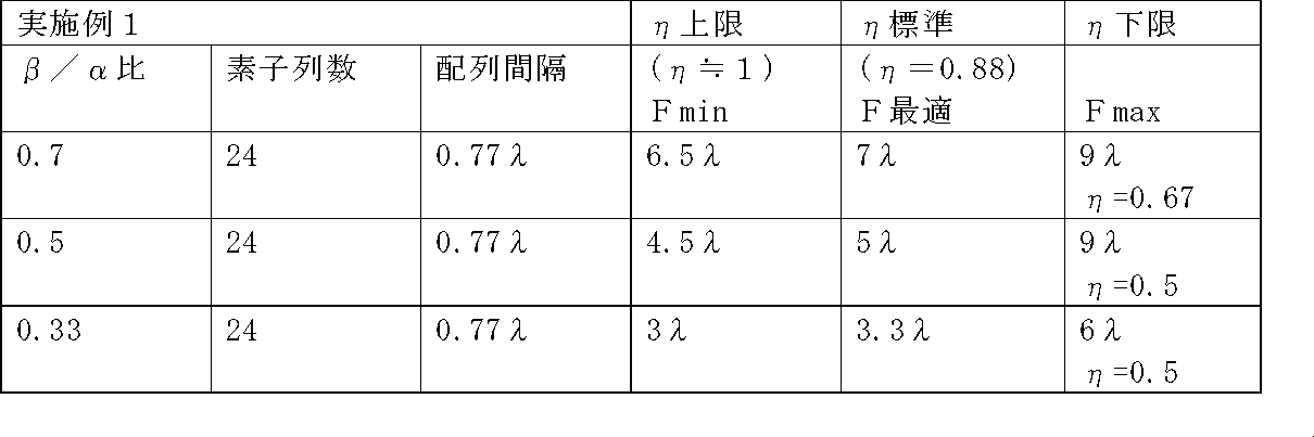
- F is optimum (an optimum value in the selection range of F).
- ⁇ is the upper limit, in the case of the standard, the measured value of F in the case of the lower limit is as many as the wavelength ⁇ .
- the conventional wavelength and the conventional wavelength are in any case in Table 2 above. It can be seen that the same or smaller value is obtained.
- the connection portion of the input terminal in FIG. When the two-branched transmission line is used as a bifurcated transmission line, the two mountain-shaped input terminal junctions that are branched into two are the set positions, and when not branched, the opening center of the mountain-shaped input terminal of the connection destination is set. It becomes a position.
- the concept of this set position has been made conventionally, and is similarly applied to the output terminal. The same applies to Table 3 described later.
- G in the present invention may be how small compared to the G in the prior art, describing, G 1 in the present invention with respect to G 0 in the prior art, at least, 0.25G 0 ⁇ G 1 ⁇ 0.80G 0
- the realization in the range of is technically possible, and based on Table 2, 0.33G 0 ⁇ G 1 ⁇ 0.67G 0 It can be derived by the above-mentioned expression that it is in the range of further, 0.33G 0 ⁇ G 1 ⁇ 0.5G 0 It should be mentioned that very good results have been obtained in the implementation in the range of
- Example 3 (Supplementary explanation for Example 3) Similarly, actual measurement results corresponding to Example 3 are summarized in the following Table 3.
- FIG. 10 An enlarged view of the slot plate 50 is shown in FIG. 10 (A), and an enlarged view of the antenna substrate 52 is shown in FIG. 10 (B).
- the slot plate 50 is provided with a plurality of slots 54 vertically and horizontally. Each slot 54 is arranged to substantially match the arrangement of each radiating element 56 on the antenna substrate 52.
- rivet holes 101 are provided in the slot plate 50 and the antenna substrate 52 at the positions which coincide with each other, respectively, and are riveted so as to be integrated with other substrates described later.
- a first ground conductor 53 is shown in FIG.
- FIG. 11A a Rotman lens substrate is shown in FIG. 11B, and a second ground conductor is shown in FIG.
- a first connection hole 59 and a rivet hole 101 are provided on the first ground conductor 53.
- a second connection hole 15 and a rivet hole 101 are provided on the second ground conductor 13.
- the rivet holes are for integrally riveting the laminated substrates and the like.
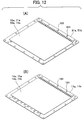
- the metal spacers 51a and 51b are shown in FIG. 12A, and the metal spacers 11a and 11b are shown in FIG. 12B. Inside the respective spacers, air gaps 55a, 55b, 14a, 14b are provided, or dielectrics 71a, 71b are filled.
- the rivet holes 101 provided in the periphery of the spacer are provided so as to coincide with the rivet holes provided in other substrates etc. when stacked, and are used to integrally rivet the laminated substrates etc. It is a thing.
- Antenna element 50 Slot plate 51a, 51b Metal spacer 52 Antenna substrate 53 First ground conductor 54 Slot 55a, 55b Air gap 56 Radiation element 57 Feeding line 58 First connection 59 1st connection hole 61, 61, ... 6n output terminal and antenna Transmission line 71a connecting the element, 71b the substrate support dielectric
Landscapes
- Aerials With Secondary Devices (AREA)
- Variable-Direction Aerials And Aerial Arrays (AREA)
- Waveguide Aerials (AREA)
- Details Of Aerials (AREA)
Abstract
Description
である。
前記入力端子または前記出力端子の素子列数nを決定する段階と、
前記素子列の配置間隔Pを決定する段階と、
前記ビームのビーム数及びビームステップ角を決定する段階と、
空間における前記アレーアンテナのビーム形成角度を前記アレーアンテナ正面からみてβとし、かつ前記出力端子(31),(32),・・・(3n)の配置される部分曲線及び前記ロトマンレンズの中心線(8)の交点S2と前記複数の入力端子の1つとを結ぶ線と、中心線(8)とがなす角度をαとしたとき、β<αとなるようαに対するβの比を設定する段階と、
b2-4ac=0となるFxを算出する段階と、
F値を決定する段階と、
G値を決定する段階と、
前記素子数nに対応するN個の出力端子座標(x,y)、及び各出力端子の補正線路位相wを算出する段階と
からなる設計ステップによって設計されたことにより、
S3を、入力端子(21),(22),・・・(2m)の配置される部分曲線と中心線(8)との交点とし、ロトマンレンズの大きさGをS2とS3との距離としたとき、Gをβ=αの条件で設計した場合のロトマンレンズの大きさよりも小さくなるよう前記ロトマンレンズの形状が決定されたことを特徴とする。
ただし、
であり、
本発明にかかるマルチビームアンテナ装置において、空間でのアレーアンテナ(5)のビーム形成方向βが、出力端子(31),(32),・・・(3n)の配置される部分曲線及び中心線(8)の交点S2と入力端子とを結ぶ線と、中心線(8)とがなす仰角αに対して、β<αの条件において、S3は、入力端子(21),(22),・・・(2m)の配置される部分曲線と中心線(8)との交点とし、Fは入力端子(21)とS2との距離、GはS2とS3との距離でロトマンレンズの大きさ、2Lnはアレーアンテナ(5)の開口長としたとき、第6式の関係式を満足するようにロトマンレンズの形状を決定して、ロトマンレンズの大きさGをβ=αの限定条件で設計した基本設計寸法未満の大きさとしたことを特徴とする。
次に、本発明にかかるマルチビームアンテナ装置における各部材の寸法等からみた実施例を、図2に沿って説明する。スロット板(50)、第1の地導体(53)、第2の地導体(13)、金属スペーサ(51a,51b)、金属スペーサ(11a,11b)は、厚さ0.3mmのアルミ板を用いた。また、基板支持誘電体(71a,71b)は、厚さ0.3mmで比誘電率約1.1の発泡ポリエチレンフォームを用いた。アンテナ基板(52)及びロトマンレンズ基板(12)は、ポリイミドフィルム(例えば、厚み25μm)に銅箔(例えば、厚み25μm)を貼り合わせたフレキシブル基板を用い、不要な銅箔をエッチングで除去して放射素子(56)、給電線路(57)、第1の接続部(58)及びロトマンレンズ(1)、伝送線路部(7)、伝送線路(7)の接続端子部(16)、入力端子部(17)を形成した。地導体とスロット板及び金属スペーサは、すべてアルミ板に機械プレスで打ち抜き加工したものを用いた。
さらに、本発明にかかるマルチビームアンテナ装置では、図5に示すように、入力端子(521),(522),・・・(52m)の接続部を2分岐伝送線路として電力を分散供給することにより、各入力端子からロトマンレンズ(1)内部に給電された電力を出力端子(531),(532),・・・(53n)の中央部に集中させて、ロトマンレンズ(1)の出力端子が配置される部分曲線の出力端子(531),(532),・・・(53n)の無い領域への電力の拡散を抑制して、不要な内部反射成分を低減することで、アレーアンテナ(5)の放射ビームのサイドローブ特性の悪化を抑制することができる。また、特に入力端子(521)や(52m)のように入力端子が配置される部分曲線の端部から入力する場合、接続部の2分岐伝送線路に位相差を設けて電力供給することにより、ロトマンレンズ(1)内部に給電された電力の伝播方向性を制御することができ、出力端子(531),(532),・・・(53n)の中央部に集中させて、アレーアンテナ(5)の放射ビームのサイドローブ特性の悪化を抑制することができる。
なお、かかる効果は、図6に示した効果を何ら損なうものではなく、むしろ相乗するものである。
背景技術の欄で述べたように、ロトマンの考え方に基づくレンズ設計は、通常、β=αの条件のもとで設計される。また、本発明の特徴は、β<αの条件において、既に述べたロトマンの変形手法を用いて従来のロトマンレンズ設計に基づいたレンズ設計を可能としたことである。すなわち、β<αの条件においては、β(アンテナ素子側の放射角度)がα(ロトマンレンズ側のビーム角度)よりも小さいため、本発明は、狭角度に対して高い解像度を必要とする場合に特に有効である。例えば、本発明にかかるマルチビームアンテナ装置を車両に搭載した場合、車両正面に対して垂直な向きを0度として左右15度程度までの範囲(つまり、左右トータルで30度程度までの開き角を有する)に対して鋭敏な検知能力を発揮できるので好適である。
すなわち、本発明にかかるアンテナ装置は、車載用アンテナ装置等に求められる理想的な電力分布及び位相分布を得ることができる。
個々に励振でき、電力を供給する複数個の入力素子と上記電力を取り出す複数個の出力素子を備えた平行平板と、
複数個の素子アンテナで構成され、空間に電波を放射するアレーアンテナとを結ぶ伝送線路と
からなり、
入力素子が配列される曲線上の三つの焦点をもとに、上記出力素子が配列される曲線および伝送線路の長さを決定し、
所定の入力素子を励振したときその入力素子に対応した角度方向にビームが放射されるようにしたアンテナ装置において、上記入力素子が配列される曲線の形状が円の一部でない
ことを特徴とするアンテナ装置、
である。
そして、特許文献3に記載の発明について考察するに、β(アンテナ素子側の放射角度)をα(ロトマンレンズ側のビーム角度)よりも大きくする必要がある用途としては、例えば広角な範囲を少ない位相誤差で検知する軍事用レーダなどが考えられる。
このビームスキャン用平面アンテナにおけるロトマンレンズの設計にあたっては、従来どおりα=βの条件のものでの設計が行われていたが、同文献の図2の指向特性からも読み取れるように、同文献の平面アンテナの有する素子数は、本発明における素子数よりも少ないものであった。したがって、アンテナ素子の数が増えてアレーアンテナの開口2Lnが大きくなる場合は、入力端子とS2との距離Fもアレーアンテナの開口2Lnに比例して大きくする必要があり、結果としてロトマンレンズの大きさGが大きくなってしまうという課題を生じさせることとなっていたことはすでに述べたとおりである。そこで、本発明はかかる課題を解決し、損失増加を抑制するようなロトマンレンズ設計を可能にし、利得向上を可能とする低損失マルチビームアンテナ装置を提供することができたものである。
本発明の特徴は、β<αの条件においてロトマンの変形手法を用いて従来のロトマンレンズ設計に基づいたレンズ設計を可能としたことであるが、本発明にかかるロトマンの変形手法を図9A及び図9Bに示すフローチャートに基づいて更に詳細に説明する。
1.136F0<G<1.4F0
となる。
1.136FX<G<1.4FX
となる。
上記式6で示した条件
0.33≦β/α<1
であり、ηが上限の場合、標準の場合、下限の場合を、それぞれ次のとおり想定している。
(1)ηが上限の場合
η=(β/α)・(Ln/F)≒1となる場合であり、このときFは最小(Fの選択範囲のうちで最小値)となる。
(2)ηが標準の場合
η=(β/α)・(Ln/F)=0.88となる場合であり、このときFは最適(Fの選択範囲のうちで最適値)となる。
(3)ηが下限の場合
η=(β/α)・(Ln/F)≦0.5~0.7となる場合であり、このときFは最大(Fの選択範囲のうちで最大値)となる。
そして、ηが上限の場合、標準の場合、下限の場合におけるFの実測値は波長λの何倍となるか、表にまとめると次の表2のとおりとなる。
なお、2Ln(=(n-1)P)は、アレーアンテナ(5)の開口長であるが、アンテナ基板(52)に設けられる放射素子(56)の一方の端の列の素子(中心部)と他方の端の列の素子(中心部)との距離を示す。
角度βは、放射素子(56)からスロット板側に引いた垂線と放射素子からビームが放射される方向とのなす角度を示す。
本発明において、設定した入力端子のX、Y座標及び式5、式6等に基づいて算出した出力端子のX、Y座標からロトマンレンズを設計する際、例えば、図5において入力端子の接続部を2分岐伝送線路とする場合には、2分岐された先にある2つの山型入力端子接合点が設定位置となり、分岐しない場合には、接続先の山型入力端子の開口中央部が設定位置となる。なお、この設定位置に対する考え方は従来からなされてきたものであり、出力端子についても同様に適用される。そして、後述の表3においても同様に適用される。
また、本発明におけるGが従来技術におけるGと比べてどの程度小さくできるかについて、説明すると、従来技術におけるG0に対して本発明におけるG1は、
少なくとも、
0.25G0<G1<0.80G0
の範囲での実現が技術的には可能であり、表2に基づけば、
0.33G0<G1<0.67G0
の範囲になっていることが既出の式によって導出できるであろう。さらに、
0.33G0<G1<0.5G0
の範囲での実施において、非常に良好な結果が得られていることを述べておく。
同様に、実施例3に対応する実測結果を次の表3にまとめる。

最後に、図2に示した本発明にかかるマルチビームアンテナ装置の構成について、補足的に説明しておく。すでに図2においても明らかであるが、スロット板50の拡大図を図10(A)に、アンテナ基板52の拡大図を図10(B)にそれぞれ示す。図10において、スロット板50には複数のスロット54が縦横に設けられている。各スロット54は、アンテナ基板52上の各放射素子56の配置と略一致するように配置されている。そして、スロット板50及びアンテナ基板52には重ね合わせたときに一致する位置にそれぞれリベット孔101が設けられており、後述する他の基板等とともに一体化するようリベット締めされる。
また、第1の地導体53を図11(A)に、ロトマンレンズ基板を図11(B)に、第2の地導体を図11(C)にそれぞれ示す。図11において、第1の地導体53上には、第1の接続孔59とリベット孔101とが設けられている。また、第2の地導体13上には、第2の接続孔15とリベット孔101が設けられている。リベット孔は積層された基板等を一体的にリベット締めするためのものである。
また、金属スペーサ51a、51bを図12(A)に、金属スペーサ11a、11bを図12(B)に示す。それぞれのスペーサ内側には、空隙部55a、55b、14a、14bが設けられるか、あるいは誘電体71a、71bが充填されている。スペーサ周辺部に設けられたリベット孔101は、重ねあわされたときに他の基板等に設けられたリベット孔と一致するように設けられ、積層された基板等を一体的にリベット締めするためのものである。
5 アレーアンテナ
7 伝送線路部
8 ロトマンレンズの中心線
9 入力端子の位置を表す補助線
10 アレーアンテナの正面方向から見たビームの方向
11a、11b 金属スペーサ
12 ロトマンレンズ基板
13 第2の地導体
14a、14b 空隙部
15 第2の接続孔
16 伝送線路の接続端子部
17 マルチビームアンテナ装置の入力端子部
21、22、・・・2m ロトマンレンズ入力端子
31、32、・・・3n ロトマンレンズ出力端子
41、42、・・・4n アンテナ素子
50 スロット板
51a、51b 金属スペーサ
52 アンテナ基板
53 第1の地導体
54 スロット
55a、55b 空隙部
56 放射素子
57 給電線路
58 第1の接続部
59 第1の接続孔
61、61、・・・6n 出力端子とアンテナ素子とを結ぶ伝送線路
71a、71b 基板支持誘電体
Claims (13)
- 電力を供給する複数の入力端子(21),(22),・・・(2m)及び前記複数の入力端子の電力を取り出すための複数の出力端子(31),(32),・・・(3n)から形成されるロトマンレンズと、複数のアンテナ素子で構成され空間に電波を放射するアレーアンテナと、前記出力端子と前記アンテナ素子とを結ぶ伝送線路からなり、前記複数の出力端子が配列される曲線及び前記伝送線路の長さを決定して、所定の入力端子を励振したとき当該入力端子に対応した角度方向にビームが形成されるマルチビームアンテナ装置において、
空間における前記アレーアンテナのビーム形成角度を前記アレーアンテナ正面からみてβとし、かつ前記出力端子(31),(32),・・・(3n)の配置される部分曲線及び前記ロトマンレンズの中心線(8)の交点S2と前記複数の入力端子の1つとを結ぶ線と、中心線(8)とがなす角度をαとしたとき、β<αであり、さらに
Fを入力端子(21)とS2との距離とし、2Lnをアレーアンテナの開口長とし、S3を、入力端子(21),(22),・・・(2m)の配置される部分曲線と中心線(8)との交点とし、ロトマンレンズの大きさGをS2とS3との距離とし、2Lnを前記アレーアンテナの開口長としたき、
の関係式を満たし、Gをβ=αの条件で設計した場合のロトマンレンズの大きさよりも小さくするよう前記ロトマンレンズの形状を決定したことを特徴とするマルチビームアンテナ装置。
- 前記ロトマンレンズをトリプレートで構成することを特徴とする請求項1に記載のマルチビームアンテナ装置。
- 前記アレーアンテナをトリプレートで構成することを特徴とする請求項2に記載のマルチビームアンテナ装置。
- 前記複数の入力端子部を2分岐伝送線路として電力を分散供給することを特徴とする請求項1~3のいずれか1項に記載のマルチビームアンテナ装置。
- 電力を供給する複数の入力端子(21),(22),・・・(2m)及び前記複数の入力端子の電力を取り出すための複数の出力端子(31),(32),・・・(3n)から形成されるロトマンレンズと、複数のアンテナ素子で構成され空間に電波を放射するアレーアンテナと、前記出力端子と前記アンテナ素子とを結ぶ伝送線路からなり、前記複数の出力端子が配列される曲線及び前記伝送線路の長さを決定して、所定の入力端子を励振したとき当該入力端子に対応した角度方向にビームが形成されるマルチビームアンテナ装置において、
空間における前記アレーアンテナのビーム形成角度を前記アレーアンテナ正面からみてβとし、かつ前記出力端子(31),(32),・・・(3n)の配置される部分曲線及び前記ロトマンレンズの中心線(8)の交点S2と前記複数の入力端子の1つとを結ぶ線と、中心線(8)とがなす角度をαとしたとき、β<αであり、S3を、入力端子(21),(22),・・・(2m)の配置される部分曲線と中心線(8)との交点とし、ロトマンレンズの大きさGをS2とS3との距離としたとき、Gをβ=αの条件で設計した場合のロトマンレンズの大きさよりも小さくするよう前記ロトマンレンズの形状を決定したことを特徴とするマルチビームアンテナ装置。 - 前記ロトマンレンズをトリプレートで構成することを特徴とする請求項5に記載のマルチビームアンテナ装置。
- 前記アレーアンテナをトリプレートで構成することを特徴とする請求項6に記載のマルチビームアンテナ装置。
- 前記複数の入力端子部を2分岐伝送線路として電力を分散供給することを特徴とする請求項5~7のいずれか1項に記載のマルチビームアンテナ装置。
- 電力を供給する複数の入力端子(21),(22),・・・(2m)及び前記複数の入力端子の電力を取り出すための複数の出力端子(31),(32),・・・(3n)から形成されるロトマンレンズと、複数のアンテナ素子で構成され空間に電波を放射するアレーアンテナと、前記出力端子と前記アンテナ素子とを結ぶ伝送線路からなり、前記複数の出力端子が配列される曲線及び前記伝送線路の長さを決定して、所定の入力端子を励振したとき当該入力端子に対応した角度方向にビームが形成されるマルチビームアンテナ装置であって、前記ロトマンレンズは、
前記入力端子または前記出力端子の素子列数nを決定する段階と、
前記素子列の配置間隔Pを決定する段階と、
前記ビームのビーム数及びビームステップ角を決定する段階と、
空間における前記アレーアンテナのビーム形成角度を前記アレーアンテナ正面からみてβとし、かつ前記出力端子(31),(32),・・・(3n)の配置される部分曲線及び前記ロトマンレンズの中心線(8)の交点S2と前記複数の入力端子の1つとを結ぶ線と、中心線(8)とがなす角度をαとしたとき、β<αとなるようαに対するβの比を設定する段階と、
b2-4ac=0となるFxを算出する段階と、
F値を決定する段階と、
G値を決定する段階と、
前記素子数nに対応するN個の出力端子座標(x,y)、及び各出力端子の補正線路位相wを算出する段階と
からなる設計ステップによって設計されたことにより、
S3を、入力端子(21),(22),・・・(2m)の配置される部分曲線と中心線(8)との交点とし、ロトマンレンズの大きさGをS2とS3との距離としたとき、Gをβ=αの条件で設計した場合のロトマンレンズの大きさよりも小さくなるよう前記ロトマンレンズの形状が決定されたことを特徴とするマルチビームアンテナ装置。
ただし、

であり、
である。
- 電力を供給する複数の入力端子(21),(22),・・・(2m)及び前記複数の入力端子の電力を取り出すための複数の出力端子(31),(32),・・・(3n)から形成されるロトマンレンズと、複数のアンテナ素子で構成され空間に電波を放射するアレーアンテナと、前記出力端子と前記アンテナ素子とを結ぶ伝送線路からなり、前記複数の出力端子が配列される曲線及び前記伝送線路の長さを決定して、所定の入力端子を励振したとき当該入力端子に対応した角度方向にビームが形成されるマルチビームアンテナ装置において、
空間における前記アレーアンテナのビーム形成角度を前記アレーアンテナ正面からみてβとし、かつ前記出力端子(31),(32),・・・(3n)の配置される部分曲線及び前記ロトマンレンズの中心線(8)の交点S2と前記複数の入力端子の1つとを結ぶ線と、中心線(8)とがなす角度をαとしたとき、β<αであることを特徴とする車載用マルチビームアンテナ装置。 - 前記ロトマンレンズをトリプレートで構成することを特徴とする請求項10に記載の車載用マルチビームアンテナ装置。
- 前記アレーアンテナをトリプレートで構成することを特徴とする請求項11に記載の車載用マルチビームアンテナ装置。
- 前記複数の入力端子部を2分岐伝送線路として電力を分散供給することを特徴とする請求項10~12のいずれか1項に記載のマルチビームアンテナ装置。
Priority Applications (4)
| Application Number | Priority Date | Filing Date | Title |
|---|---|---|---|
| CN200980155542.3A CN102301527B (zh) | 2008-11-28 | 2009-11-30 | 多波束天线装置 |
| US13/131,752 US8698689B2 (en) | 2008-11-28 | 2009-11-30 | Multi-beam antenna device |
| KR1020117014799A KR101266698B1 (ko) | 2008-11-28 | 2009-11-30 | 멀티빔 안테나 장치 |
| EP09829186.7A EP2372835A4 (en) | 2008-11-28 | 2009-11-30 | MULTIPLE ANTENNA ARRANGEMENT |
Applications Claiming Priority (2)
| Application Number | Priority Date | Filing Date | Title |
|---|---|---|---|
| JP2008303781 | 2008-11-28 | ||
| JP2008-303781 | 2008-11-28 |
Publications (1)
| Publication Number | Publication Date |
|---|---|
| WO2010061948A1 true WO2010061948A1 (ja) | 2010-06-03 |
Family
ID=42225810
Family Applications (1)
| Application Number | Title | Priority Date | Filing Date |
|---|---|---|---|
| PCT/JP2009/070108 Ceased WO2010061948A1 (ja) | 2008-11-28 | 2009-11-30 | マルチビームアンテナ装置 |
Country Status (6)
| Country | Link |
|---|---|
| US (1) | US8698689B2 (ja) |
| EP (1) | EP2372835A4 (ja) |
| JP (1) | JP5838465B2 (ja) |
| KR (1) | KR101266698B1 (ja) |
| CN (1) | CN102301527B (ja) |
| WO (1) | WO2010061948A1 (ja) |
Families Citing this family (17)
| Publication number | Priority date | Publication date | Assignee | Title |
|---|---|---|---|---|
| US8866691B2 (en) * | 2007-04-20 | 2014-10-21 | Skycross, Inc. | Multimode antenna structure |
| EP2624475B1 (en) * | 2012-01-31 | 2015-01-28 | Fraunhofer-Gesellschaft zur Förderung der angewandten Forschung e.V. | Combined Power Transmission |
| JP6003811B2 (ja) * | 2013-06-05 | 2016-10-05 | 日立金属株式会社 | アンテナ装置 |
| US9780457B2 (en) | 2013-09-09 | 2017-10-03 | Commscope Technologies Llc | Multi-beam antenna with modular luneburg lens and method of lens manufacture |
| US9368870B2 (en) * | 2014-03-17 | 2016-06-14 | Ubiquiti Networks, Inc. | Methods of operating an access point using a plurality of directional beams |
| CN104319466A (zh) * | 2014-09-25 | 2015-01-28 | 东南大学 | 多波束扫描天线 |
| KR102435550B1 (ko) * | 2015-06-09 | 2022-08-24 | 주식회사 에이치엘클레무브 | 레이더 신호처리 장치 및 그 신호처리방법 |
| US11329393B2 (en) * | 2016-12-07 | 2022-05-10 | Fujikura Ltd. | Antenna device |
| US10230166B2 (en) * | 2017-04-18 | 2019-03-12 | The Boeing Company | Plasma switched array antenna |
| KR102242282B1 (ko) | 2017-06-26 | 2021-04-20 | 후아웨이 테크놀러지 컴퍼니 리미티드 | 전력 공급 장치 |
| CN108172998A (zh) * | 2017-12-21 | 2018-06-15 | 四川中测微格科技有限公司 | 一种提高波束成形网络器件端口隔离度的结构 |
| CN108562876A (zh) * | 2018-01-31 | 2018-09-21 | 中国电子科技集团公司第三十八研究所 | 宽带低副瓣模拟多波束阵列侦察系统 |
| JP7152190B2 (ja) * | 2018-05-28 | 2022-10-12 | 矢崎総業株式会社 | 検出機器及び検出システム |
| KR102129897B1 (ko) * | 2019-06-12 | 2020-07-03 | 조선대학교산학협력단 | 가변 빔폭을 갖는 빔틸팅 안테나 장치 |
| WO2021231725A1 (en) * | 2020-05-14 | 2021-11-18 | The Regents Of The University Of California | Parametric flat lenses for near-field imaging and electronic beam scanning |
| CN114512824B (zh) * | 2022-03-11 | 2023-10-24 | 电子科技大学 | 基于共腔罗特曼透镜的毫米波十字扫描多波束阵列天线 |
| KR20260033543A (ko) * | 2023-12-21 | 2026-03-10 | 엘지전자 주식회사 | 복수의 로트만 렌즈들을 포함하는 신호전송장치 |
Citations (5)
| Publication number | Priority date | Publication date | Assignee | Title |
|---|---|---|---|---|
| JPS56123105A (en) | 1980-03-04 | 1981-09-28 | Tech Res & Dev Inst Of Japan Def Agency | Antenna device |
| JPS5793701A (en) | 1980-12-03 | 1982-06-10 | Mitsubishi Electric Corp | Antenna device |
| JPS57184305A (en) | 1981-05-09 | 1982-11-13 | Mitsubishi Electric Corp | Antenna device |
| JP2000124727A (ja) | 1998-10-20 | 2000-04-28 | Hitachi Chem Co Ltd | ビームスキャン用平面アンテナ |
| JP2003152422A (ja) * | 2001-11-19 | 2003-05-23 | Mitsubishi Electric Corp | アレイアンテナ装置 |
Family Cites Families (8)
| Publication number | Priority date | Publication date | Assignee | Title |
|---|---|---|---|---|
| DE19951123C2 (de) * | 1999-07-30 | 2003-11-13 | Volkswagen Ag | Radarsensor für ein Überwachen der Umgebung eines Kraftfahrzeuges |
| EP1291966B1 (en) * | 2000-04-18 | 2010-08-11 | Hitachi Chemical Company, Ltd. | Planar antenna for beam scanning |
| US6480167B2 (en) * | 2001-03-08 | 2002-11-12 | Gabriel Electronics Incorporated | Flat panel array antenna |
| JP2007189596A (ja) * | 2006-01-16 | 2007-07-26 | Nippon Hoso Kyokai <Nhk> | ビームフォーミング装置 |
| US7724197B1 (en) * | 2007-04-30 | 2010-05-25 | Planet Earth Communications, Llc | Waveguide beam forming lens with per-port power dividers |
| JP5146138B2 (ja) * | 2008-06-19 | 2013-02-20 | 富士通株式会社 | 無線通信装置および送信ビーム制御方法 |
| EP2393156B1 (en) * | 2009-01-29 | 2014-12-03 | Hitachi Chemical Company, Ltd. | Multi-beam antenna apparatus |
| JP2012222523A (ja) * | 2011-04-06 | 2012-11-12 | Hitachi Chem Co Ltd | アンテナ走査装置及びそれを用いた無線通信システム |
-
2009
- 2009-11-30 CN CN200980155542.3A patent/CN102301527B/zh not_active Expired - Fee Related
- 2009-11-30 US US13/131,752 patent/US8698689B2/en active Active
- 2009-11-30 WO PCT/JP2009/070108 patent/WO2010061948A1/ja not_active Ceased
- 2009-11-30 EP EP09829186.7A patent/EP2372835A4/en not_active Ceased
- 2009-11-30 JP JP2009271889A patent/JP5838465B2/ja active Active
- 2009-11-30 KR KR1020117014799A patent/KR101266698B1/ko not_active Expired - Fee Related
Patent Citations (5)
| Publication number | Priority date | Publication date | Assignee | Title |
|---|---|---|---|---|
| JPS56123105A (en) | 1980-03-04 | 1981-09-28 | Tech Res & Dev Inst Of Japan Def Agency | Antenna device |
| JPS5793701A (en) | 1980-12-03 | 1982-06-10 | Mitsubishi Electric Corp | Antenna device |
| JPS57184305A (en) | 1981-05-09 | 1982-11-13 | Mitsubishi Electric Corp | Antenna device |
| JP2000124727A (ja) | 1998-10-20 | 2000-04-28 | Hitachi Chem Co Ltd | ビームスキャン用平面アンテナ |
| JP2003152422A (ja) * | 2001-11-19 | 2003-05-23 | Mitsubishi Electric Corp | アレイアンテナ装置 |
Non-Patent Citations (3)
| Title |
|---|
| JAEHEUNG KIM ET AL.: "Scaling and focusing of the Rotman lens", ANTENNAS AND PROPAGATION SOCIETY INTERNATIONAL SYMPOSIUM. IEEE, vol. 2, 2001, pages 773 - 776, XP010564202 * |
| KATAGI, T. ET AL.: "An improved design method of Rotman lens antennas, Antennas and Propagation", IEEE TRANSACTIONS ON, vol. 32, no. ISS.5, 1984, pages 524 - 527, XP008140475 * |
| See also references of EP2372835A4 * |
Also Published As
| Publication number | Publication date |
|---|---|
| JP2010154522A (ja) | 2010-07-08 |
| KR101266698B1 (ko) | 2013-05-28 |
| US8698689B2 (en) | 2014-04-15 |
| CN102301527A (zh) | 2011-12-28 |
| KR20110091023A (ko) | 2011-08-10 |
| JP5838465B2 (ja) | 2016-01-06 |
| EP2372835A1 (en) | 2011-10-05 |
| US20110241968A1 (en) | 2011-10-06 |
| CN102301527B (zh) | 2015-06-24 |
| EP2372835A4 (en) | 2015-06-17 |
Similar Documents
| Publication | Publication Date | Title |
|---|---|---|
| WO2010061948A1 (ja) | マルチビームアンテナ装置 | |
| CN102369634B (zh) | 多波束天线装置 | |
| JP4803172B2 (ja) | 平面アンテナモジュール、トリプレート型平面アレーアンテナ、およびトリプレート線路−導波管変換器 | |
| KR101832976B1 (ko) | 단벽 슬롯형 도파관 어레이들을 급전하기 위한 빔형성 네트워크 | |
| CN100373695C (zh) | 天线控制单元和相控阵天线 | |
| KR20110023768A (ko) | 트리플레이트 선로 층간 접속기 및 평면 어레이 안테나 | |
| Potelon et al. | Reconfigurable CTS antenna fully integrated in PCB technology for 5G backhaul applications | |
| US20100085133A1 (en) | Triplate line-to-waveguide transducer | |
| US9711870B2 (en) | Folded radiation slots for short wall waveguide radiation | |
| CN105379011A (zh) | 电子可控的人工阻抗表面天线 | |
| CN115428260B (zh) | 阵列天线模块及其制备方法、相控阵天线系统 | |
| JP2018207478A (ja) | 広帯域アンテナシステム | |
| US12088012B2 (en) | Apparatus radiating and receiving microwaves with physically preset radiation pattern, and radar apparatus comprising such an apparatus | |
| Lijarcio et al. | Low-cost center-fed slot array based on gap waveguide mlw coaxial line technology for e-band automotive radar | |
| US20100194656A1 (en) | Leaky wave antenna using waves propagating between parallel surfaces | |
| JP2003051708A (ja) | アンテナ | |
| Potelon et al. | Continuous Transverse Stub Antenna in PCB Technology |
Legal Events
| Date | Code | Title | Description |
|---|---|---|---|
| WWE | Wipo information: entry into national phase |
Ref document number: 200980155542.3 Country of ref document: CN |
|
| 121 | Ep: the epo has been informed by wipo that ep was designated in this application |
Ref document number: 09829186 Country of ref document: EP Kind code of ref document: A1 |
|
| WWE | Wipo information: entry into national phase |
Ref document number: 13131752 Country of ref document: US |
|
| NENP | Non-entry into the national phase |
Ref country code: DE |
|
| ENP | Entry into the national phase |
Ref document number: 20117014799 Country of ref document: KR Kind code of ref document: A |
|
| WWE | Wipo information: entry into national phase |
Ref document number: 2009829186 Country of ref document: EP |