WO2010064482A1 - プラスチック袋の製造方法および製袋機 - Google Patents
プラスチック袋の製造方法および製袋機 Download PDFInfo
- Publication number
- WO2010064482A1 WO2010064482A1 PCT/JP2009/066664 JP2009066664W WO2010064482A1 WO 2010064482 A1 WO2010064482 A1 WO 2010064482A1 JP 2009066664 W JP2009066664 W JP 2009066664W WO 2010064482 A1 WO2010064482 A1 WO 2010064482A1
- Authority
- WO
- WIPO (PCT)
- Prior art keywords
- web material
- adhesive
- sheet
- belt
- bag
- Prior art date
- Legal status (The legal status is an assumption and is not a legal conclusion. Google has not performed a legal analysis and makes no representation as to the accuracy of the status listed.)
- Ceased
Links
Images



Classifications
-
- B—PERFORMING OPERATIONS; TRANSPORTING
- B31—MAKING ARTICLES OF PAPER, CARDBOARD OR MATERIAL WORKED IN A MANNER ANALOGOUS TO PAPER; WORKING PAPER, CARDBOARD OR MATERIAL WORKED IN A MANNER ANALOGOUS TO PAPER
- B31B—MAKING CONTAINERS OF PAPER, CARDBOARD OR MATERIAL WORKED IN A MANNER ANALOGOUS TO PAPER
- B31B70/00—Making flexible containers, e.g. envelopes or bags
-
- B—PERFORMING OPERATIONS; TRANSPORTING
- B31—MAKING ARTICLES OF PAPER, CARDBOARD OR MATERIAL WORKED IN A MANNER ANALOGOUS TO PAPER; WORKING PAPER, CARDBOARD OR MATERIAL WORKED IN A MANNER ANALOGOUS TO PAPER
- B31B—MAKING CONTAINERS OF PAPER, CARDBOARD OR MATERIAL WORKED IN A MANNER ANALOGOUS TO PAPER
- B31B70/00—Making flexible containers, e.g. envelopes or bags
- B31B70/74—Auxiliary operations
- B31B70/86—Forming integral handles or mounting separate handles
- B31B70/876—Forming integral handles or mounting separate handles involving application of reinforcement strips or patches; involving reinforcements obtained by folding
-
- B—PERFORMING OPERATIONS; TRANSPORTING
- B31—MAKING ARTICLES OF PAPER, CARDBOARD OR MATERIAL WORKED IN A MANNER ANALOGOUS TO PAPER; WORKING PAPER, CARDBOARD OR MATERIAL WORKED IN A MANNER ANALOGOUS TO PAPER
- B31B—MAKING CONTAINERS OF PAPER, CARDBOARD OR MATERIAL WORKED IN A MANNER ANALOGOUS TO PAPER
- B31B2160/00—Shape of flexible containers
- B31B2160/10—Shape of flexible containers rectangular and flat, i.e. without structural provision for thickness of contents
-
- B—PERFORMING OPERATIONS; TRANSPORTING
- B31—MAKING ARTICLES OF PAPER, CARDBOARD OR MATERIAL WORKED IN A MANNER ANALOGOUS TO PAPER; WORKING PAPER, CARDBOARD OR MATERIAL WORKED IN A MANNER ANALOGOUS TO PAPER
- B31B—MAKING CONTAINERS OF PAPER, CARDBOARD OR MATERIAL WORKED IN A MANNER ANALOGOUS TO PAPER
- B31B70/00—Making flexible containers, e.g. envelopes or bags
- B31B70/60—Uniting opposed surfaces or edges; Taping
- B31B70/62—Uniting opposed surfaces or edges; Taping by adhesives
- B31B70/626—Arrangements for permitting the glue to set
-
- B—PERFORMING OPERATIONS; TRANSPORTING
- B31—MAKING ARTICLES OF PAPER, CARDBOARD OR MATERIAL WORKED IN A MANNER ANALOGOUS TO PAPER; WORKING PAPER, CARDBOARD OR MATERIAL WORKED IN A MANNER ANALOGOUS TO PAPER
- B31B—MAKING CONTAINERS OF PAPER, CARDBOARD OR MATERIAL WORKED IN A MANNER ANALOGOUS TO PAPER
- B31B70/00—Making flexible containers, e.g. envelopes or bags
- B31B70/74—Auxiliary operations
- B31B70/86—Forming integral handles or mounting separate handles
- B31B70/864—Mounting separate handles on bags, sheets or webs
-
- B—PERFORMING OPERATIONS; TRANSPORTING
- B31—MAKING ARTICLES OF PAPER, CARDBOARD OR MATERIAL WORKED IN A MANNER ANALOGOUS TO PAPER; WORKING PAPER, CARDBOARD OR MATERIAL WORKED IN A MANNER ANALOGOUS TO PAPER
- B31B—MAKING CONTAINERS OF PAPER, CARDBOARD OR MATERIAL WORKED IN A MANNER ANALOGOUS TO PAPER
- B31B70/00—Making flexible containers, e.g. envelopes or bags
- B31B70/74—Auxiliary operations
- B31B70/86—Forming integral handles or mounting separate handles
- B31B70/864—Mounting separate handles on bags, sheets or webs
- B31B70/87—Applying handles on one side of a moving longitudinally folded web, e.g. after cutting a tubular web longitudinally; Applying handles on both sides of a moving web and folding this web longitudinally afterwards
Definitions
- the present invention relates to a plastic bag manufacturing method and a bag making machine.
- Patent Document 1 Japanese Patent No. 3733085
- Patent Document 2 Japanese Patent No. 3733085
- a side gusset bag in a bag making machine for producing a plastic bag, a web material is supplied from a roll, and the plastic bag is produced by the web material.
- the plastic bag in a bag making machine for producing a plastic bag, a web material is supplied from a roll, and the plastic bag is produced by the web material.
- the plastic bag is called a side gusset bag, and has a barrel portion and a side gusset portion.
- the side gusset portion extends along both side edges of the barrel portion, is folded between both layers of the barrel portion, and is folded in two. Therefore, the plastic bag can be expanded by the side gusset portion to increase its capacity.
- the plastic bag disclosed in the publication has a bottom portion in addition to the body portion and the side gusset portion.
- the body material, the side gusset material and the bottom material are used as the web material, the body material, the side gusset material and the bottom material are supplied from the roll, the body part is formed by the body material, and the side gusset part is formed by the side gusset material.
- the bottom portion is formed by the bottom material.
- the body material and the side gusset material are used as the web material, the body material and the side gusset material are supplied from the roll, the body portion and the bottom portion are formed by the body material, and the side gusset portion is formed by the side gusset material. You can also. This is what is described in Japanese Patent No. 3655627 (Patent Document 2).
- Patent Document 3 Japanese Patent Laid-Open No. 2-109868
- a belt-like sheet is attached to the outer surface of a plastic film, and a handle is formed by the belt-like sheet.
- the belt-like sheet is attached to the outer surface of the side gusset bag and the handle is formed by the belt-like sheet, but the problem is the adhesive. .
- the weight is considerably large as described above. Even if the belt-like sheet is pasted with hot melt adhesive or instant adhesive, the adhesive strength is not sufficient, and the handle is formed by the belt-like sheet. However, when the side gusset bag is hung, the handle may peel off due to the weight and may be separated.
- the strong adhesive is an adhesive having a large adhesive strength.
- many strong adhesives require a curing time.
- the adhesive sheet is hardly bonded until the curing time has elapsed, and the belt-like sheet is firmly attached. It is not possible. For this reason, for example, it is necessary to keep the belt-like sheet and the side gusset bag stationary for at least 10 minutes after the application. If the side gusset bag is fed at a high speed before the lapse of time, the belt-like sheet may be displaced and may be peeled off. Therefore, in a side gusset bag making machine, it is not realistic to attach the belt-like sheet with a strong adhesive requiring a curing time.
- a manufacturing method having a special configuration is newly provided.
- a strong adhesive and another adhesive are applied to one side of a belt-like sheet or web material.
- a strong adhesive is of a type that requires a curing time.
- the belt-like sheet and the web material face each other and are pressed against each other, and a strong adhesive and another adhesive are interposed therebetween, and the belt-like sheet and the web material are temporarily fixed by the other adhesive.
- the web material is wound on a roll, and after the aging time of the strong adhesive has elapsed, the web material is supplied from the roll in the bag making machine that produces the plastic bag, and the plastic bag is produced by the web material.
- a handle is formed by a belt-like sheet on the outer surface of the plastic bag.
- the belt-like sheet and the web material face each other and are pressed, and a strong adhesive and other adhesive material are interposed between each sheet and the web material, and other adhesives.
- a strong adhesive and other adhesive material are interposed between each sheet and the web material, and other adhesives.
- the web material consists of a laminate film in which a base material and a sealant are laminated. And when a strip
- Sealant consists of polyethylene or polypropylene layer.
- the base material is disposed upward, the sealant is disposed downward, and the web material is fed in this state. Furthermore, when tension is applied to the web material, the sealant engages the scraping means, and when a strong adhesive or other adhesive is attached to the sealant, the adhesive adhered by the scraping means is scraped off, Thereafter, a plastic bag is manufactured from the web material.
- a bag making machine having a special configuration is newly provided.
- a web material is supplied from a roll, and a plastic bag is manufactured by the web material.
- the belt-like sheet and the web material face each other and are pressed, and a strong adhesive and another adhesive are interposed between each sheet and the web material.
- a strong adhesive is of a type that requires a curing time.
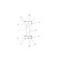
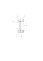
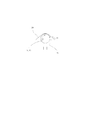
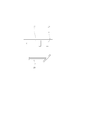
- FIG. 2 is a side view of the handle material, the belt-like sheet, and the web material of FIG. It is an enlarged view of the strip
- the handle material 1 is supplied from the roll 2, passes through the tension roller 3, is guided to the feed roller 4, and the handle material 1 is fed by the feed roller 4.
- the handle material 1 is made of a plastic film, the feed roller 4 is continuously rotated, and the handle material 1 is continuously fed. Further, the handle material 1 passes through the dancer roller 5, the movable clamp 6, the fixed clamp 7, the Thomson blade 8, the perforation forming blade 9, the adhesive applicator 10, the draining device 11, the movable clamp 12 and the separating device 13, and the fixed clamp 14 leads to.
- the movable clamps 6 and 12 are closed by the driving mechanism such as an air cylinder, the fixed clamps 7 and 14 are opened, and the handle material 1 is clamped by the movable clamps 6 and 12 and released from the fixed clamps 7 and 14.
- the movable clamps 6 and 12 are supported by the timing belt, and the timing belt is driven by the drive motor, so that the movable clamps 6 and 12 move.
- the moving direction is the length direction of the handle material 1, the movable clamp 6 moves toward the fixed clamp 7, approaches the fixed clamp 7, the movable clamp 12 moves toward the fixed clamp 14, and the fixed clamp 14. To approach.
- the movement distances are the same. Therefore, the handle material 1 is pulled and fed by the movable clamps 6 and 12.
- the fixed clamps 7 and 14 are closed by the drive mechanism, the movable clamps 6 and 12 are opened, and the handle material 1 is clamped by the fixed clamps 7 and 14 and released from the movable clamps 6 and 12. Thereafter, the movable clamps 6 and 12 move in the reverse direction and return to their original positions. Thereafter, the handle material 1 is clamped to the movable clamps 6 and 12, released from the fixed clamps 7 and 14, and the movable clamps 6 and 12 move again. This process is repeated alternately and the handle material 1 is sent intermittently. Accordingly, the dancer roller 5 is raised and lowered by the tension, and the handle material 1 is supplied from the dancer roller 5 and stored in the dancer roller 5.
- the belt-like sheet 17 is formed by the handle material 1.
- the perforation forming blade 9 is pressed against the handle material 1 and the cradle 15 to form perforations 18 on the belt-like sheet 17 as shown in FIG. Therefore, the belt-like sheet 17 is also made of a plastic film.
- the cutting line 16 is discontinuous and has a plurality of micro joints. A micro joint is a minute connection part and is formed at intervals.
- the belt-like sheet 17 has a predetermined shape, and both end portions 19 have a large width. Therefore, the belt-like sheet 17 and the waste 20 are formed for each intermittent feed, the respective sheets 17 and the waste 20 are connected by the micro joint, and the handle material 1 is fed in this state.
- the strong adhesive 21 is supplied from the coating device 10 and applied to one side of the belt-like sheet 17.
- the dust removal device 11 is pressed against the handle material 1 and the pedestal 22, the dust 20 is pushed down by the dust removal device 11, the micro joint is torn off, and the dust 20 is removed and falls.
- the scraping device 11 is pressed against the handle member 1 and the pedestal 22, the handle member 1 is sandwiched between the scraping device 11 and the pedestal 22, but thereafter the handle member 1 is kept in that state and fixed.
- the separating device 13 is pressed against the handle material 1 between the clamp 14 and the combing device 11. Therefore, the handle material 1 is pushed down by the separating device 13, the micro joint is torn off, and the belt-like sheet 17 is separated from the next belt-like sheet.
- the strip-shaped sheet 17 is separated, when the movable clamp 12 is closed and the fixed clamp 14 is opened, the strip-shaped sheet 17 is attracted to the vacuum suction belt 23. Thereafter, the vacuum suction belt 23 is driven by the drive motor, and the belt-like sheet 17 is fed. The belt-like sheet 17 is fed a certain distance. Further, when the belt-like sheet 17 is fed by the vacuum suction belt 23, the belt-like sheet 17 passes through the adhesive application device 24, and another adhesive 25 is sprayed from the coating device 24 and applied to one side of the belt-like sheet 17.
- the adhesive application devices 10 and 24 are disposed above the belt-like sheet 17, and the strong adhesive 21 and the other adhesive 25 are applied to the upper surface of the belt-like sheet 17. Further, a presser plate 26 is disposed above the cradle 27, and the belt-like sheet 17 is fed by the vacuum suction belt 23, and the belt-like sheet 17 is placed between the presser plate 26 and the cradle 27.
- the strong adhesive 21 is applied over a considerable area, and the other adhesive 25 is applied to each corner.
- the strong adhesive 21 is of a type that requires a curing time.
- the other adhesive 25 is a hot melt adhesive or an instantaneous adhesive.
- the web material 28 is supplied from the roll 29, passes through the tension roller 30, is guided to the feed roller 31, and the web material 28 is fed by the feed roller 31.
- the feed roller 31 is continuously rotated, and the web material 28 is continuously fed.
- the web material 28 passes through the dancer roller 32, is guided between the pressing plate 26 and the cradle 27, passes through the mark sensor 33, is guided to the feed roller 34, and the web material 28 is fed by the feed roller 34.
- the belt-like sheet 17 is sent by the vacuum suction belt 23 and is disposed between the presser plate 26 and the cradle 27.
- the belt-like sheet 17 is It is arranged below the web material 28. Further, marks are attached to the surface of the web material 28 at fixed lengths, and the marks are detected by the mark sensor 33. The feed roller 34 is stopped by the control device based on the detection signal, and the web material is detected. 28 stops.
- the presser plate 26 is pushed down by the drive mechanism, and the presser plate 26 is pressed against the web material 28, the belt-like sheet 17 and the cradle 27. Accordingly, the belt-like sheet 17 and the web material 28 face each other and are pressed against each other, and the strong adhesive 21 and the other adhesive 25 are interposed therebetween, and the belt-like sheet 17 and the web material 28 are temporarily fixed by the other adhesive 25. Is done. In this embodiment, the belt-like sheet 17 is temporarily fixed to the lower surface of the web material 28. Further, when the presser plate 26 is pressed against the web material 28, the belt-like sheet 17 and the cradle 27, the web material 28 and the belt-like sheet 17 are sandwiched between the presser plate 26 and the cradle 27.
- the sheet 17 is maintained in that state, the receiving base 27 is pushed up by the drive mechanism, and the presser plate 26 is pulled up. Accordingly, the web material 28 and the belt-like sheet 17 are pulled up by the cradle 27 and the presser plate 26, and the belt-like sheet 17 is pulled away from the vacuum suction belt 23. Thereafter, the presser plate 26 and the cradle 27 are returned to their original positions.
- the feed roller 34 is rotated by the control device, and the web material 28 is fed again. Further, the belt-like sheet 17 is fed by the vacuum suction belt 23, and then the feeding roller 34 and the web material 28 are stopped again, and the belt-like sheet 17 is temporarily fixed again. Therefore, when the feed roller 34 rotates intermittently and the web material 28 is intermittently fed and the web material 28 is stopped every intermittent feed, the belt-like sheet 17 is temporarily fixed to one surface of the web material 28. Is. Further, when the web material 28 is intermittently fed, the dancer roller 32 is raised and lowered by tension, and the web material 28 is supplied from the dancer roller 32 and stored in the dancer roller 32.
- the belt-like sheet 17 and the web material 28 face each other and are pressed for each predetermined length of the web material 28.
- the strong adhesive 21 and the other adhesive 25 are interposed between each sheet 17 and the web material 28, and each sheet 17 and the web material 28 are temporarily fixed by the other adhesive 25.
- the belt-like sheet 17 When the belt-like sheet 17 is sent by the vacuum suction belt 23, the belt-like sheet 17 is sent in the width direction.
- the web material 28 is fed by the feed roller 34, and the feed direction is a direction perpendicular to the feed direction of the belt-like sheet 17. Therefore, the belt-like sheet 17 extends in the length direction of the web material 28 when temporarily fixed to one surface of the web material 28.
- the web material 28 passes through the dancer roller 35 and is guided to the roll 36.
- a drive motor is connected to the powder clutch and the winding shaft 37, the winding shaft 37 is rotated by the drive motor and the powder clutch, and the web material 28 is wound around the roll 36.
- the winding shaft 37 rotates continuously, and the web material 28 is continuously wound.
- the dancer roller 35 is raised and lowered by tension, and the web material 28 is supplied from the dancer roller 35 and stored in the dancer roller 35.
- the touch roller 38 engages with the web material 28 and the roll 36, and contact pressure is applied by the touch roller 38, so that the web material 28 is accurately wound.
- the outer diameter of the roll 36 is measured by the touch roller 38, and when the predetermined outer diameter is reached, the drive motor can be stopped by the control device, and the feed rollers 31, 34 and the winding shaft 37 can be stopped.
- the belt-like sheet 17 is temporarily fixed to the lower surface of the web material 28 as described above.
- the web material 28 is made of a laminate film obtained by laminating a base material and a sealant, and when the web material 28 is fed, the base material is disposed downward and the sealant is disposed upward. Therefore, when the belt-like sheet 17 is temporarily fixed to the substrate and wound up, the sealant is superimposed on the belt-like sheet 17.
- the substrate consists of a nylon or PET layer and the sealant consists of a polyethylene or polypropylene layer.
- the roll 36 is supported by the roll support mechanism, and the web material 28 is supplied from the roll 36.
- Guided to bag making means 39 For example, after elapse of 30 minutes or more, in the bag making machine, the roll 36 is supported by the roll support mechanism, and the web material 28 is supplied from the roll 36.
- the bag making means 39 has a feed roller, a heat seal device and a cutter. The feed roller is for feeding the web material, the heat seal device is for heat sealing the web material, and the cutter is for cutting the web material.
- the base material is disposed upward, the sealant is disposed downward, and the web material 28 is fed in that state.
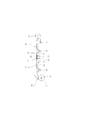
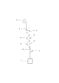
- the web material 28 is guided to the tension roller 40, tension is applied to the web material 28, and the web material 28 is guided to the feed roller 43 through the scraping means 41, the scraping means 42, and the feed roller 43.
- the feed roller 43 rotates continuously, and the web material 28 is fed continuously.
- the scraping means 41 and 42 are made of a chrome-plated roller, and the roller does not rotate.
- the adhesive adhered by the scraping means 41 and 42 is scraped off, which is repeated a plurality of times, and then the web material 28 is moved to the dancer roller. 44 through the bag making means 39. Further, the hopper 45 is disposed below the scraping means 41 and 42 and connected to the blower. When the adhered adhesive is scraped off, it is sucked and discharged by the hopper 45 and the blower.
- a chrome-plated roller may be used for the scraping means 41, 42, and this may be rotated in a direction X2 opposite to the feed direction X1 of the web material 28. In this case, even if the tension is low, the adhered adhesive can be effectively scraped off.
- a brush roller may be used for the scraping means 41, 42.
- the web material 28 is guided to the bag making means 39, the web material 28 is fed by the feed roller, it is heat-sealed and cut by the heat sealing device and the cutter, and the plastic bag is manufactured by the web material 28.
- the web material 28 is a side gusset material.
- a body material 46 is used as a web material, which is supplied from a roll, and the side gusset material 28 is arranged in the width direction as in the case of Japanese Patent No. 3733085. Folded from both sides, cut to a certain length, and supplied to the body 46.
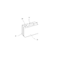
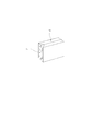
- the side gusset material 28 has a center line 47 and a fold line 48, and is folded along the fold line 48. When folded in half, the belt-like sheet 17 is folded in two along the perforation 18. Then, as shown in FIG. 9, the body portion is formed by the body material 46, and the side gusset portion is formed by the side gusset material 28. It is also possible to use a bottom material 49 as the web material, which is supplied from a roll, and the bottom material 49 forms a bottom portion. Like the thing of the patent 3655627 gazette, a trunk
- the body 46 and the bottom material 49 are also made of a laminate film in which a base material and a sealant are laminated. And the outer surface of a bag is formed with a base material, and the inner surface of a bag is formed with a sealant. Therefore, a handle is formed by the belt-like sheet 17 on the outer surface of the plastic bag.
- a side gusset portion is formed by the side gusset material 28, and a handle is formed by the belt-like sheet 17 on the outer surface of the side gusset portion.
- the belt-like sheet 17 and the web material 28 are temporarily fixed by the other adhesive 25, and this is wound around the roll 36. Therefore, the belt-like sheet 17 is not peeled off from the web material 28 until it is wound on the roll 36, and there is no problem.
- the belt-like sheet 17 is sandwiched between the web material 28 and the web material 28 and kept in that state.
- tension can be applied to the web material 28 to compress the belt-like sheet 17 between the web material 28 and the web material 28.
- the pressure can be adjusted by the tension. Therefore, the belt-like sheet 17 and the web material 28 can be pressed against each other and kept in that state.
- the web material 28 is supplied from the roll 36 in a bag making machine that manufactures plastic bags.
- the belt-like sheet 17 is attached to one side of the web material 28 and supplied from the roll 36.
- the belt-like sheet 17 is attached not only with the other adhesive 25 but also with the strong adhesive 21, and there is no problem of the curing time of the strong adhesive 21, and the adhesive strength is extremely high. Therefore, when the handle is formed by the belt-like sheet 17 and the plastic bag is hung, there is no problem of the adhesive strength, and the handle is peeled off due to the weight and is not likely to be separated.
- the belt-like sheet 17 is sandwiched between the web material 28 and the web material 28, and the strong adhesive 21 may protrude around the belt-like sheet 17 due to pressure. Therefore, when applying the strong adhesive 21 to one side of the belt-like sheet 17, it is preferable to select an appropriate application region so that the strong adhesive 21 does not protrude due to pressure. As shown in FIG. 4, another adhesive 25 may be applied around the strong adhesive 21 so that the strong adhesive 21 does not protrude around the belt-like sheet 17 due to the other adhesive 25. The other adhesive 25 may not be applied at the predetermined location 50, and the strong adhesive 21 may pass through the predetermined location 50 and protrude to the central portion of the belt-like sheet 17.
- the sealant when the web material 28 is wound on the roll 36, the sealant is superimposed on the belt-like sheet 17. In this case, there is no problem even if the strong adhesive 21 protrudes around the belt-like sheet 17.
- the sealant acts as a release paper and is peeled off from the protruding adhesive. Therefore, the web material 28 can be smoothly unwound and supplied.
- the sealant is composed of a polyethylene or polypropylene layer as described above. In this case, even if the strong adhesive 21 protrudes, the sealant is peeled off smoothly, and the web material 28 is smoothly unwound and supplied. That has been confirmed.
- the protruding adhesive does not adhere to the sealant. If attached, it is kept to a minimum. Further, as described above, the adhesive adhered by the scraping means 41 and 42 is scraped off thereafter. Therefore, thereafter, when the outer surface of the bag is formed by the base material and the inner surface of the bag is formed by the sealant, the adhered adhesive does not remain in the bag.
- the strong adhesive 21 and the other adhesive 25 are applied to one side of the belt-like sheet 17, but conversely, the strong adhesive and the other adhesive are applied to one side of the web material 28,
- the belt-like sheet 17 and the web material 28 may face each other and may be pressed.
- the belt-like sheet 17 is attached to one side of the web material, and the web material constitutes the body material or the bottom material instead of the side gusset material, which is supplied from the roll, and as shown in FIG. 10 and FIG.
- the handle can be formed by the belt-like sheet 17 on the outer surface of the bottom portion.
Landscapes
- Making Paper Articles (AREA)
- Bag Frames (AREA)
- Lining Or Joining Of Plastics Or The Like (AREA)
Abstract
Description
21 強力接着剤
25 他の接着剤
10,13 塗布装置
26 押え板
28 ウエブ材
36 ロール
39 製袋手段
41,42 擦り落し手段
Claims (7)
- 養生時間を要する強力接着剤と他の接着剤を帯状シートまたはウエブ材の片面に塗布する工程と、
前記帯状シートとウエブ材を互いに対面させ、押し付け、両者間に前記強力接着剤と他の接着剤を介在させ、前記他の接着剤によって前記帯状シートとウエブ材を仮止めする工程と、
仮止め後、前記ウエブ材をロールに巻き取る工程と、
前記強力接着剤の養生時間の経過後、プラスチック袋を製造する製袋機において、前記ウエブ材を前記ロールから供給し、前記ウエブ材によってプラスチック袋を製造し、前記プラスチック袋の外面において、前記帯状シートによってハンドルを形成する工程とからなるプラスチック袋の製造方法。 - 前記ウエブ材の一定長さ毎に、それぞれ前記帯状シートとウエブ材を対面させ、押し付け、各シートとウエブ材間に前記強力接着剤と他の接着剤を介在させ、前記他の接着剤によって前記各シートとウエブ材を仮止めすることを特徴とする請求項1に記載の製造方法。
- 前記他の接着剤はホットメルト接着剤または瞬間接着剤であることを特徴とする請求項1に記載の製造方法。
- 前記ウエブ材は基材とシーラントをラミネートしたラミネートフィルムからなり、前記帯状シートを前記基材に仮止めし、巻き取ったとき、前記シーラントを前記帯状シートに重ね合わせることを特徴とする請求項1に記載の製造方法。
- 前記シーラントはポリエチレンまたはポリプロピレン層からなることを特徴とする請求項3に記載の製造方法。
- 前記ウエブ材を前記ロールから供給するとき、前記基材を上向きに配置し、前記シーラントを下向きに配置し、その状態で前記ウエブ材を送り、前記ウエブ材にテンションを加え、前記シーラントを擦り落し手段に係合させ、前記シーラントに前記強力接着剤または他の接着剤が付着しているとき、前記擦り落し手段によって付着した接着剤を擦り落し、その後、前記ウエブ材によってプラスチック袋を製造することを特徴とする請求項3に記載の製造方法。
- ウエブ材をロールから供給し、前記ウエブ材によってプラスチック袋を製造する製袋機であって、前記ウエブ材の一定長さ毎に、それぞれ帯状シートとウエブ材が対面し、押し付けられ、各シートとウエブ材間に強力接着剤と他の接着材が介在しており、前記強力接着剤は養生時間を要する種類のものであることを特徴とする製袋機。
Priority Applications (6)
| Application Number | Priority Date | Filing Date | Title |
|---|---|---|---|
| BRPI0922724-5A BRPI0922724A2 (ja) | 2008-12-02 | 2009-09-25 | A manufacturing method and a bag-making machine of a plastic bag |
| EP09830250.8A EP2377679A4 (en) | 2008-12-02 | 2009-09-25 | METHOD FOR PRODUCING A PLASTIC BAG AND BAG MANUFACTURING MACHINE |
| CN2009801484131A CN102256780B (zh) | 2008-12-02 | 2009-09-25 | 塑料袋制造方法及设备 |
| US13/131,960 US8715148B2 (en) | 2008-12-02 | 2009-09-25 | Plastic bag making method and apparatus |
| CA2745409A CA2745409C (en) | 2008-12-02 | 2009-09-25 | Plastic bag making method and apparatus |
| AU2009323496A AU2009323496B2 (en) | 2008-12-02 | 2009-09-25 | Plastic Bag Making Method and Apparatus |
Applications Claiming Priority (2)
| Application Number | Priority Date | Filing Date | Title |
|---|---|---|---|
| JP2008307792A JP4571214B2 (ja) | 2008-12-02 | 2008-12-02 | プラスチック袋の製造方法および製袋機 |
| JP2008-307792 | 2008-12-02 |
Publications (1)
| Publication Number | Publication Date |
|---|---|
| WO2010064482A1 true WO2010064482A1 (ja) | 2010-06-10 |
Family
ID=42233137
Family Applications (1)
| Application Number | Title | Priority Date | Filing Date |
|---|---|---|---|
| PCT/JP2009/066664 Ceased WO2010064482A1 (ja) | 2008-12-02 | 2009-09-25 | プラスチック袋の製造方法および製袋機 |
Country Status (9)
| Country | Link |
|---|---|
| US (1) | US8715148B2 (ja) |
| EP (1) | EP2377679A4 (ja) |
| JP (1) | JP4571214B2 (ja) |
| CN (1) | CN102256780B (ja) |
| AU (1) | AU2009323496B2 (ja) |
| BR (1) | BRPI0922724A2 (ja) |
| CA (1) | CA2745409C (ja) |
| RU (1) | RU2463164C1 (ja) |
| WO (1) | WO2010064482A1 (ja) |
Families Citing this family (4)
| Publication number | Priority date | Publication date | Assignee | Title |
|---|---|---|---|---|
| JP6025338B2 (ja) | 2012-02-08 | 2016-11-16 | 株式会社フジシールインターナショナル | 製袋機 |
| DE102013105381A1 (de) * | 2013-05-24 | 2014-11-27 | Windmöller & Hölscher Kg | Beutel, Verfahren zur Herstellung eines Beutels sowie Maschinensystem zur Herstellung eines Beutels |
| CN113854776B (zh) * | 2021-11-11 | 2024-08-23 | 广州市联柔机械设备有限公司 | 可拆解的袋装弹簧串制造设备 |
| US20250187289A1 (en) * | 2023-12-11 | 2025-06-12 | Hallmark Cards, Incorporated | System and method for automated placement of hang tabs on gift bags and other items |
Citations (7)
| Publication number | Priority date | Publication date | Assignee | Title |
|---|---|---|---|---|
| JPH02109868A (ja) | 1988-07-14 | 1990-04-23 | Okura Ind Co Ltd | 手提げ用取っ手のついた収縮包装体 |
| JPH03173633A (ja) * | 1989-12-01 | 1991-07-26 | Taiyo Shokai:Kk | 提げハンドル付き合成樹脂フイルム製袋の製造装置 |
| JPH05269892A (ja) * | 1991-11-12 | 1993-10-19 | Mead Corp:The | 板紙の接着方法および板紙製品 |
| JPH0885554A (ja) * | 1994-09-19 | 1996-04-02 | New Oji Paper Co Ltd | 使いすて衛生用品の包装袋 |
| JP2005053488A (ja) * | 2003-08-04 | 2005-03-03 | Kyodo Printing Co Ltd | 把手付包装体の製造方法および把手付包装体 |
| JP3655627B2 (ja) | 2002-07-24 | 2005-06-02 | トタニ技研工業株式会社 | 製袋機 |
| JP3733085B2 (ja) | 2002-06-03 | 2006-01-11 | トタニ技研工業株式会社 | プラスチック袋およびその製袋機 |
Family Cites Families (13)
| Publication number | Priority date | Publication date | Assignee | Title |
|---|---|---|---|---|
| GB1272898A (en) * | 1969-10-08 | 1972-05-03 | P & B Agencies Proprietary Ltd | Improvements in or relating to bags |
| DE2248613A1 (de) * | 1972-10-04 | 1974-04-18 | Windmoeller & Hoelscher | Vorrichtung zum aufkleben von tragschlaufen mittels eines verstaerkungsblattes auf eine voranbewegte bahn beim herstellen von tragbeuteln |
| CA1187845A (en) * | 1982-02-23 | 1985-05-28 | Marinus J.M. Langen | Handle for carrier bag and method of making handled carrier bag |
| DK161066C (da) * | 1987-03-30 | 1991-11-11 | Unibag As | Beholder af boejeligt materiale, isaer pose, samt fremgangsmaader og maskiner til fremstilling af samme |
| IT1246501B (it) * | 1990-12-05 | 1994-11-19 | S U N S R L | Apparecchiatura per il trasporto di maniglie in corda per sacchetti di carta ad una stazione per la formazione di questi ultimi con applicazione delle stesse all'ingresso di detta stazione prima che i sacchetti vengano realizzati. |
| DE4238655C2 (de) * | 1992-11-16 | 2002-10-24 | Windmoeller & Hoelscher | Verfahren zur Herstellung von Beuteln aus Papier |
| US5662576A (en) * | 1993-09-29 | 1997-09-02 | Compac International, Inc. | Method of manufacturing an improved bag for the cultivation of mushroom spawn and apparatus therefor |
| FR2710610B1 (fr) * | 1993-10-01 | 1997-01-24 | Joseph Meynard | Procédé de fabrication d'une poignée pour sac en papier ou d'un autre matériau. |
| US5609556A (en) * | 1994-05-27 | 1997-03-11 | Fischer & Krecke Gmbh & Co. | Method and apparatus for manufacturing bags with strap-shaped carrying handles |
| JPH1059418A (ja) * | 1996-08-20 | 1998-03-03 | Dainippon Printing Co Ltd | 把っ手集合体およびその取り付け方法 |
| MXPA03001835A (es) * | 2000-08-29 | 2003-06-04 | Nestle Sa | Recipiente para alojar producto y metodo para la fabricacion del mismo. |
| CN200978087Y (zh) * | 2006-11-07 | 2007-11-21 | 黄国年 | 热收缩膜包装袋的提手 |
| BRPI0721310A2 (pt) * | 2007-01-12 | 2013-01-29 | Alcan Packaging Arenzano S P A | recipiente, e, mÉtodo para produzir o mesmo |
-
2008
- 2008-12-02 JP JP2008307792A patent/JP4571214B2/ja not_active Expired - Fee Related
-
2009
- 2009-09-25 EP EP09830250.8A patent/EP2377679A4/en not_active Withdrawn
- 2009-09-25 CN CN2009801484131A patent/CN102256780B/zh not_active Expired - Fee Related
- 2009-09-25 US US13/131,960 patent/US8715148B2/en not_active Expired - Fee Related
- 2009-09-25 RU RU2011127154/12A patent/RU2463164C1/ru not_active IP Right Cessation
- 2009-09-25 CA CA2745409A patent/CA2745409C/en not_active Expired - Fee Related
- 2009-09-25 AU AU2009323496A patent/AU2009323496B2/en not_active Ceased
- 2009-09-25 BR BRPI0922724-5A patent/BRPI0922724A2/ja not_active IP Right Cessation
- 2009-09-25 WO PCT/JP2009/066664 patent/WO2010064482A1/ja not_active Ceased
Patent Citations (7)
| Publication number | Priority date | Publication date | Assignee | Title |
|---|---|---|---|---|
| JPH02109868A (ja) | 1988-07-14 | 1990-04-23 | Okura Ind Co Ltd | 手提げ用取っ手のついた収縮包装体 |
| JPH03173633A (ja) * | 1989-12-01 | 1991-07-26 | Taiyo Shokai:Kk | 提げハンドル付き合成樹脂フイルム製袋の製造装置 |
| JPH05269892A (ja) * | 1991-11-12 | 1993-10-19 | Mead Corp:The | 板紙の接着方法および板紙製品 |
| JPH0885554A (ja) * | 1994-09-19 | 1996-04-02 | New Oji Paper Co Ltd | 使いすて衛生用品の包装袋 |
| JP3733085B2 (ja) | 2002-06-03 | 2006-01-11 | トタニ技研工業株式会社 | プラスチック袋およびその製袋機 |
| JP3655627B2 (ja) | 2002-07-24 | 2005-06-02 | トタニ技研工業株式会社 | 製袋機 |
| JP2005053488A (ja) * | 2003-08-04 | 2005-03-03 | Kyodo Printing Co Ltd | 把手付包装体の製造方法および把手付包装体 |
Non-Patent Citations (1)
| Title |
|---|
| See also references of EP2377679A4 * |
Also Published As
| Publication number | Publication date |
|---|---|
| JP4571214B2 (ja) | 2010-10-27 |
| AU2009323496A1 (en) | 2011-07-21 |
| JP2010131783A (ja) | 2010-06-17 |
| EP2377679A1 (en) | 2011-10-19 |
| CA2745409C (en) | 2014-12-16 |
| CN102256780A (zh) | 2011-11-23 |
| RU2463164C1 (ru) | 2012-10-10 |
| CN102256780B (zh) | 2013-08-14 |
| US20110237414A1 (en) | 2011-09-29 |
| CA2745409A1 (en) | 2010-06-10 |
| EP2377679A4 (en) | 2015-07-08 |
| BRPI0922724A2 (ja) | 2018-11-06 |
| US8715148B2 (en) | 2014-05-06 |
| AU2009323496B2 (en) | 2013-07-25 |
Similar Documents
| Publication | Publication Date | Title |
|---|---|---|
| AU2017412310B2 (en) | Automatic packaging film and a method for preparing the same | |
| CN102076491B (zh) | 制袋机 | |
| JP5525534B2 (ja) | ラベル形成用基材対 | |
| CN102803076A (zh) | 带有卡扣带的包装袋的制造方法及其制造装置 | |
| US20240100800A1 (en) | Packaging with multi-ply walls | |
| JP4571214B2 (ja) | プラスチック袋の製造方法および製袋機 | |
| CN115697687A (zh) | 改进的包装袋 | |
| EP3684587B1 (en) | Apparatus and method for embedding an elastic cord | |
| JP6574911B1 (ja) | ジョイントテープ、それを利用した包装用フィルムの連結方法および連結装置 | |
| WO2013128629A1 (ja) | ラベルの製造方法 | |
| CN113968044B (zh) | 一种外卖手提袋的制造装置及其制造方法 | |
| JP2004231268A (ja) | 緩衝封筒、その製造方法および製造装置 | |
| KR20110087120A (ko) | 롤형 종이백 제조 방법 | |
| JP2002255229A (ja) | 易開封機能付き袋包装用フィルム及びその製造方法 | |
| CN221757002U (zh) | 缓冲片材制作模组及包装袋制作设备 | |
| JP2011011788A (ja) | 包装用フィルム及びその製造方法、並びにその製造装置 | |
| JP2002332013A (ja) | 袋口部自動封緘装置 | |
| JP4139273B2 (ja) | 粘着テープ貼り付け装置及び貼り付け方法 | |
| JPS5854029B2 (ja) | 袋体、その製造法およびその製造装置 | |
| JP3559110B2 (ja) | 合成樹脂フィルムがラミネートされた立体紙袋及びその製造方法 | |
| JPH01198335A (ja) | ポリプロピレン樹脂製角筒状包装袋の製造方法 | |
| JPS6343073Y2 (ja) | ||
| KR100837997B1 (ko) | 합성수지 필름 봉투 제조방법 | |
| JP2001150553A (ja) | デリバリー袋及びその製造方法 | |
| JPH0885507A (ja) | 巻き付け式包装機 |
Legal Events
| Date | Code | Title | Description |
|---|---|---|---|
| WWE | Wipo information: entry into national phase |
Ref document number: 200980148413.1 Country of ref document: CN |
|
| 121 | Ep: the epo has been informed by wipo that ep was designated in this application |
Ref document number: 09830250 Country of ref document: EP Kind code of ref document: A1 |
|
| WWE | Wipo information: entry into national phase |
Ref document number: 2745409 Country of ref document: CA |
|
| WWE | Wipo information: entry into national phase |
Ref document number: 2326/KOLNP/2011 Country of ref document: IN |
|
| NENP | Non-entry into the national phase |
Ref country code: DE |
|
| WWE | Wipo information: entry into national phase |
Ref document number: 13131960 Country of ref document: US |
|
| WWE | Wipo information: entry into national phase |
Ref document number: 2009323496 Country of ref document: AU |
|
| REEP | Request for entry into the european phase |
Ref document number: 2009830250 Country of ref document: EP |
|
| WWE | Wipo information: entry into national phase |
Ref document number: 2009830250 Country of ref document: EP |
|
| WWE | Wipo information: entry into national phase |
Ref document number: 2011127154 Country of ref document: RU |
|
| ENP | Entry into the national phase |
Ref document number: 2009323496 Country of ref document: AU Date of ref document: 20090925 Kind code of ref document: A |
|
| ENP | Entry into the national phase |
Ref document number: PI0922724 Country of ref document: BR Kind code of ref document: A2 Effective date: 20110602 |