WO2010064555A1 - 炭素触媒及びその製造方法、これを用いた電極及び電池 - Google Patents
炭素触媒及びその製造方法、これを用いた電極及び電池 Download PDFInfo
- Publication number
- WO2010064555A1 WO2010064555A1 PCT/JP2009/069777 JP2009069777W WO2010064555A1 WO 2010064555 A1 WO2010064555 A1 WO 2010064555A1 JP 2009069777 W JP2009069777 W JP 2009069777W WO 2010064555 A1 WO2010064555 A1 WO 2010064555A1
- Authority
- WO
- WIPO (PCT)
- Prior art keywords
- carbon
- carbon catalyst
- catalyst
- metal
- electrode
- Prior art date
- Legal status (The legal status is an assumption and is not a legal conclusion. Google has not performed a legal analysis and makes no representation as to the accuracy of the status listed.)
- Ceased
Links
Images


Classifications
-
- C—CHEMISTRY; METALLURGY
- C01—INORGANIC CHEMISTRY
- C01B—NON-METALLIC ELEMENTS; COMPOUNDS THEREOF; METALLOIDS OR COMPOUNDS THEREOF NOT COVERED BY SUBCLASS C01C
- C01B32/00—Carbon; Compounds thereof
- C01B32/05—Preparation or purification of carbon not covered by groups C01B32/15, C01B32/20, C01B32/25, C01B32/30
-
- H—ELECTRICITY
- H01—ELECTRIC ELEMENTS
- H01M—PROCESSES OR MEANS, e.g. BATTERIES, FOR THE DIRECT CONVERSION OF CHEMICAL ENERGY INTO ELECTRICAL ENERGY
- H01M4/00—Electrodes
- H01M4/86—Inert electrodes with catalytic activity, e.g. for fuel cells
- H01M4/88—Processes of manufacture
-
- H—ELECTRICITY
- H01—ELECTRIC ELEMENTS
- H01M—PROCESSES OR MEANS, e.g. BATTERIES, FOR THE DIRECT CONVERSION OF CHEMICAL ENERGY INTO ELECTRICAL ENERGY
- H01M4/00—Electrodes
- H01M4/86—Inert electrodes with catalytic activity, e.g. for fuel cells
- H01M4/8605—Porous electrodes
-
- H—ELECTRICITY
- H01—ELECTRIC ELEMENTS
- H01M—PROCESSES OR MEANS, e.g. BATTERIES, FOR THE DIRECT CONVERSION OF CHEMICAL ENERGY INTO ELECTRICAL ENERGY
- H01M4/00—Electrodes
- H01M4/86—Inert electrodes with catalytic activity, e.g. for fuel cells
- H01M4/96—Carbon-based electrodes
-
- C—CHEMISTRY; METALLURGY
- C01—INORGANIC CHEMISTRY
- C01P—INDEXING SCHEME RELATING TO STRUCTURAL AND PHYSICAL ASPECTS OF SOLID INORGANIC COMPOUNDS
- C01P2002/00—Crystal-structural characteristics
- C01P2002/60—Compounds characterised by their crystallite size
-
- H—ELECTRICITY
- H01—ELECTRIC ELEMENTS
- H01M—PROCESSES OR MEANS, e.g. BATTERIES, FOR THE DIRECT CONVERSION OF CHEMICAL ENERGY INTO ELECTRICAL ENERGY
- H01M8/00—Fuel cells; Manufacture thereof
- H01M8/10—Fuel cells with solid electrolytes
- H01M2008/1095—Fuel cells with polymeric electrolytes
-
- Y—GENERAL TAGGING OF NEW TECHNOLOGICAL DEVELOPMENTS; GENERAL TAGGING OF CROSS-SECTIONAL TECHNOLOGIES SPANNING OVER SEVERAL SECTIONS OF THE IPC; TECHNICAL SUBJECTS COVERED BY FORMER USPC CROSS-REFERENCE ART COLLECTIONS [XRACs] AND DIGESTS
- Y02—TECHNOLOGIES OR APPLICATIONS FOR MITIGATION OR ADAPTATION AGAINST CLIMATE CHANGE
- Y02E—REDUCTION OF GREENHOUSE GAS [GHG] EMISSIONS, RELATED TO ENERGY GENERATION, TRANSMISSION OR DISTRIBUTION
- Y02E60/00—Enabling technologies; Technologies with a potential or indirect contribution to GHG emissions mitigation
- Y02E60/30—Hydrogen technology
- Y02E60/50—Fuel cells
Definitions
- the present invention relates to a carbon catalyst and a method for producing the same, and an electrode and a battery using the carbon catalyst, and more particularly, to a carbon catalyst that can replace a noble metal catalyst such as platinum or palladium.
- the polymer electrolyte fuel cell can be operated in a low temperature region, has high energy conversion efficiency, has a short start-up time, and can be made compact and lightweight. For this reason, PEFC is expected to be applied to power sources for electric vehicles, portable power sources, and home cogeneration systems.
- the present invention has been made in view of the above problems, and an object thereof is to provide a carbon catalyst having excellent activity, a production method thereof, an electrode and a battery using the carbon catalyst.
- a carbon catalyst according to an embodiment of the present invention for solving the above problems has a carbon structure, and a crystallite size La distribution of 7.2 nm or less on a carbon network surface constituting the carbon structure is 1 to 5 nm.
- the ratio is 10% or more, and the ratio exceeding 5 nm is 60% or less. According to the present invention, a carbon catalyst having excellent activity can be provided.
- a carbon catalyst according to an embodiment of the present invention for solving the above problems has a carbon structure, and a crystallite size La distribution of 7.2 nm or less on a carbon network surface constituting the carbon structure is 1 to 5 nm.
- the ratio is 10% or more, and the ratio of less than 1 nm is 70% or less. According to the present invention, a carbon catalyst having excellent activity can be provided.
- the ratio of 2 to 5 nm may be 80% or more, and the ratio of less than 2 nm may be 10% or less.
- the ratio of 3 to 5 nm may be 70% or more, and the ratio of less than 3 nm may be 20% or less. If it carries out like this, the carbon catalyst which has the outstanding activity can be provided reliably.
- the carbon structure may be a carbon structure formed by heating and carbonizing a raw material containing a resin and a metal. If it carries out like this, the carbon catalyst which has the outstanding activity can be provided reliably.
- An electrode according to an embodiment of the present invention for solving the above problems is characterized in that any one of the above carbon catalysts is supported.
- ADVANTAGE OF THE INVENTION According to this invention, the outstanding electrode by which the carbon catalyst which has the outstanding activity was carry
- a battery according to an embodiment of the present invention for solving the above-described problems has the above-described electrode.
- ADVANTAGE OF THE INVENTION According to this invention, the outstanding battery which has the electrode by which the carbon catalyst which has the outstanding activity was carry
- a method for producing a carbon catalyst according to an embodiment of the present invention for solving the above problems includes a first step of obtaining a carbon catalyst by heating and carbonizing a raw material containing a resin and a metal, and the carbon A second step of performing a treatment for removing the metal on the catalyst; and a third step of improving the activity of the carbon catalyst by performing a heat treatment on the carbon catalyst subjected to the treatment. .
- ADVANTAGE OF THE INVENTION According to this invention, the manufacturing method of the carbon catalyst which has the outstanding activity can be provided.
- the heat treatment may be performed by heating the carbon catalyst at a temperature within a range of 300 to 1500 ° C.
- the heat treatment may be performed by heating the carbon catalyst at a temperature equal to or lower than the temperature at which the raw material is heated in the first step.
- the carbon catalyst may be subjected to the treatment by washing the carbon catalyst with an acid.
- the metal may be a transition metal. If it carries out like this, the carbon catalyst which has the outstanding activity can be manufactured more effectively.
- a carbon catalyst according to an embodiment of the present invention for solving the above-described problems is characterized by being manufactured by any one of the above methods. According to the present invention, a carbon catalyst having excellent activity can be provided.
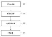
- FIG. 1 is an explanatory diagram showing main steps included in an example of a carbon catalyst production method according to the present embodiment (hereinafter referred to as “the present production method”). As shown in FIG. 1, the manufacturing method includes a raw material preparation step S1, a carbonization step S2, a metal removal step S3, and a heat treatment step S4.
- a raw material containing a resin and a metal is prepared.
- the resin is not particularly limited as long as it is a polymer material that can be carbonized in the carbonization step S2 described later. That is, for example, a thermosetting resin or a thermoplastic resin that can be carbonized can be used.
- polyvinyl pyridine polyacrylonitrile, chelate resin, cellulose, carboxymethyl cellulose, polyvinyl alcohol, polyacrylic acid, polyfurfuryl alcohol, furan resin, phenol resin, phenol formaldehyde resin, polyimidazole, melamine resin, epoxy resin, Pitch, lignite, polyvinylidene chloride, polycarbodiimide, lignin, anthracite, biomass, protein, humic acid, polyimide, polyaniline, polypyrrole, nitrogen-containing ligand polymer, and metal coordination compound can be used. These resins can be used singly or in combination of two or more.
- the resin can be a polymer ligand capable of coordinating with the metal contained in the raw material. That is, in this case, a resin containing one or more coordination atoms in the molecule is used. Specifically, for example, as a coordination atom, a resin containing one or a plurality of one or more selected from the group consisting of a nitrogen atom, a phosphorus atom, an oxygen atom, and a sulfur atom in the molecule is used. it can. That is, for example, as the coordinating group, a resin containing one or a plurality of one or more selected from the group consisting of an amino group, a phosphino group, a carboxyl group, and a thiol group can be used.
- a raw material when using resin which is a ligand, a raw material will contain the complex formed when the said resin coordinated to the metal. Therefore, the resin and the metal can be efficiently and integrally dispersed in the raw material.
- a resin containing one or more nitrogen atoms as a coordination atom in the molecule can be preferably used.
- the resin, metal, and nitrogen atom can be efficiently and integrally dispersed in the raw material.
- the nitrogen atom contained in resin brings about the effect of nitrogen dope in the carbon catalyst manufactured by this manufacturing method, and can improve the activity of the said carbon catalyst.
- a resin containing one or more nitrogen atoms in the molecule can be preferably used.
- a resin containing one or more nitrogen atoms in the molecule can be preferably used.
- PAN polyacrylonitrile
- urea resin oligomer urea resin oligomer
- melamine resin melamine resin
- the resin and the nitrogen atom can be efficiently and integrally dispersed in the raw material.
- the resin when using a resin with poor thermosetting property, the resin may be infusibilized.
- the structure of the resin can be maintained even at a temperature higher than the original melting point or softening point of the resin. Infusibilization can be performed by a known method.
- the shape of the resin and metal mixture or the metal complex of the resin is not particularly limited as long as it does not impair the activity of the carbon catalyst produced by this production method.
- it should be a sheet, fiber, block, or particle. Can do.
- the metal is not particularly limited as long as it does not inhibit the activity of the carbon catalyst produced by this production method. That is, as the metal, for example, a transition metal can be preferably used, and a metal belonging to Group 4 to Group 4 of the periodic table can be particularly preferably used.
- metals can be used singly or in combination of two or more.
- one or more selected from the group consisting of cobalt, iron, nickel, manganese, zinc, and copper can be preferably used, and cobalt and iron can be particularly preferably used.
- metal a simple substance of the metal or a compound of the metal can be used.
- metal compound for example, metal salts, metal hydroxides, metal oxides, metal nitrides, metal sulfides, metal carbonides, metal complexes can be preferably used, and metal chlorides, metal oxides, metal complexes can be used. Can be used particularly preferably.
- the raw material may contain a conductive carbon material in order to impart conductivity to the carbon catalyst.
- the conductive carbon material is not particularly limited as long as it is a carbon material having conductivity. That is, for example, a carbon material having conductivity and having no catalytic activity by itself can be used.
- the shape of the conductive carbon material is not particularly limited, and for example, a particulate material or a fibrous material can be used.
- the average particle size of the fine particles is preferably in the range of 3 to 100 nm.
- the BET specific surface area of the fine particles is preferably in the range of 100 to 2000 m 2 / g.
- the conductive carbon material for example, one or more selected from the group consisting of carbon black, carbon nanotube, carbon nanofiber, graphite, activated carbon, glassy carbon, carbon fiber, and fullerene is preferable.
- carbon black for example, ketjen black, Vulcan, Toka black, Denka black can be used.
- a raw material can be prepared by mixing such a resin and a metal. That is, the raw material can be, for example, a mixed powder of a resin metal complex and conductive carbon material fine particles.
- the method for mixing the raw materials is not particularly limited. That is, for example, mixing methods such as powder mixing, solvent mixing, supercritical fluid mixing, and electrolytic polymerization coating can be used alone or in combination of two or more.
- the proportion of the conductive carbon material contained in the raw material is preferably in the range of 1 to 85% by mass, and preferably in the range of 5 to 50% by mass. Is more preferable.
- the content of the conductive carbon material is less than 1% by mass, sufficient conductivity may not be imparted to the carbon catalyst produced by this production method.
- content of an electroconductive carbon material exceeds 85 mass%, the activity of the carbon catalyst manufactured by this manufacturing method may fall on the contrary.
- a carbon catalyst is obtained by heating and carbonizing the raw material prepared as described above. That is, the raw material is held at a predetermined temperature (carbonization temperature) at which the resin contained in the raw material can be carbonized.
- the carbonization temperature is not particularly limited, and can be appropriately set according to conditions such as the melting point and decomposition point of the resin. That is, the carbonization temperature can be, for example, in the range of 300 to 1500 ° C., preferably in the range of 500 to 1200 ° C., and more preferably in the range of 600 to 1200 ° C. And particularly preferably within the range of 700 to 1200 ° C.
- the rate of temperature rise can be in the range of 0.5 to 300 ° C./min.
- the time for holding the raw material at the above-mentioned carbonization temperature can be, for example, within a range of 5 to 180 minutes, and preferably within a range of 20 to 120 minutes. If the holding time is less than 5 minutes, the resin may not be uniformly carbonized. On the other hand, if the holding time exceeds 180 minutes, the catalytic activity may be significantly reduced due to the disappearance of the edge surface of the carbon network surface. Further, the carbonization treatment is preferably performed under a flow of an inert gas such as nitrogen.
- a carbon catalyst having a carbon structure formed by carbonization of a resin can be obtained.
- this carbon structure includes a carbon network surface constituted by a hexagonal network surface of carbon extending in a two-dimensional manner. It is considered that defective portions such as edge portions and bent portions of the carbon network surface serve as active points of the carbon catalyst.
- the carbon structure can be a structure in which a plurality of carbon network surfaces are stacked.
- the carbon catalyst obtained in the carbonization step S2 is subjected to a treatment for removing metal.
- the metal contained in the carbon catalyst can be removed or the content of the metal can be reduced.
- the method for removing the metal is not particularly limited. That is, for example, an acid cleaning process or an electrolytic process can be used. When washing with an acid, a boiled acid can be used. As the acid, for example, hydrochloric acid can be preferably used.
- the carbon catalyst that has been subjected to the metal removal treatment in the metal removal step S3 is subjected to a heat treatment to improve the activity of the carbon catalyst.
- the heat treatment is performed by holding the carbon catalyst at a predetermined temperature (heat treatment temperature).
- the heat treatment temperature can be, for example, in the range of 300 to 1500 ° C., preferably 400 ° C. or higher, more preferably 600 ° C. or higher, and particularly preferably 700 ° C. or higher. By performing the heat treatment at 600 ° C. or higher or 700 ° C. or higher, the activity of the carbon catalyst can be effectively improved. Further, the heat treatment temperature is preferably 1200 ° C. or less, and more preferably 1000 ° C. or less.
- the range of the heat treatment temperature can be a range obtained by arbitrarily combining these lower limit value and upper limit value. That is, the heat treatment temperature can be, for example, in the range of 400 ° C. to 1200 ° C., preferably in the range of 600 ° C. to 1200 ° C., and more preferably in the range of 700 to 1200 ° C. Particularly preferably, it can be in the range of 700 to 1000 ° C.
- the time for holding the carbon catalyst at these heat treatment temperatures can be, for example, in the range of 10 minutes to 5 hours, and preferably in the range of 30 minutes to 2 hours.
- the rate of temperature rise can be, for example, in the range of 0.5 to 1000 ° C./min.
- the heat treatment is preferably performed at a temperature lower than the heating temperature generally employed in so-called graphitization treatment. That is, the heat treatment can be performed, for example, by heating the carbon catalyst at a heat treatment temperature equal to or lower than the temperature at which the raw material is heated in the carbonization step S2 or at a heat treatment temperature lower than the temperature.
- the heating temperature in the carbonization treatment is in the range of 600 ° C. to 1200 ° C. or in the range of 700 ° C. to 1200 ° C.
- the heating temperature is within the range.
- the heat treatment can be performed at the following heat treatment temperature or a heat treatment temperature lower than the heating temperature.
- Such a heat treatment can effectively form, for example, structural defects serving as active points on the surface of the carbon catalyst.
- this heat treatment can remove, for example, an inactive metal component slightly remaining in the carbon catalyst after the metal removal treatment. Therefore, a more active carbon catalyst in which the active sites are effectively exposed can be obtained.
- the carbon catalyst excellent in catalyst activities, such as oxygen reduction activity can be manufactured.
- this manufacturing method can also include the process of introduce
- the method for introducing nitrogen atoms or boron atoms into the carbon catalyst is not particularly limited. That is, when doping nitrogen atoms, for example, a vapor phase doping method such as an ammoxidation method or a CVD method, a liquid phase doping method, or a gas phase-liquid phase doping method can be used.
- a carbon catalyst and a nitrogen source such as ammonia, melamine, and acetonitrile are mixed, and the mixture is subjected to an inert gas such as nitrogen, argon, and helium and an air atmosphere.
- Nitrogen atoms can be introduced to the surface of the carbon catalyst by holding at a temperature in the range of 550 to 1200 ° C. for a time in the range of 5 to 180 minutes or by heat treatment in NOx gas. .
- the nitrogen atom can be introduced into, for example, a hexagonal network structure having a carbon structure to form a pyrrole-type, graphene-substituted type, pyridine-type, pyridone-type, or oxidized-type structure.
- the carbon catalyst according to the present embodiment (hereinafter referred to as “the present catalyst”) is a carbon catalyst produced by imparting catalytic activity to the carbon material itself, and is efficiently produced by the production method as described above. Can do.
- This catalyst is a carbon catalyst having a carbon structure including a carbon network surface.
- This carbon structure can be formed, for example, by heating and carbonizing a raw material containing a resin and a metal as described above. And this carbon structure is comprised including the carbon network surface in which defect parts, such as an edge part and a bending part, were formed as an active point.
- the catalyst when the catalyst is produced by carbonizing a raw material containing a thermosetting resin and a metal (for example, a raw material containing a metal complex of a thermosetting resin), the catalyst Around the metal fine particles, it is possible to have a turbulent layer structure (nanoshell structure) similar to a graphite structure, which is laminated and developed in an onion shape. In this case, in this catalyst, it is considered that the edge portion of the carbon network surface included in the turbulent layer structure and the bent portion of the carbon network surface serve as active points, and the catalytic activity of the carbon material itself is extracted. .
- the present catalyst was produced by carbonizing a raw material containing a thermoplastic resin, a metal, and a conductive carbon material (for example, a raw material containing a metal complex of a thermoplastic resin and a conductive carbon material).
- the present catalyst can have the conductive carbon material and a carbon structure that covers the surface of the conductive carbon material.
- the carbon structure is formed as a film of the conductive carbon material in a film shape along the surface of the conductive carbon material. That is, this catalyst has, so to speak, a conductive carbon material part as a carrier (base material) and a carbon structure part (carbonized layer) including active sites formed on the surface of the conductive carbon material. It becomes.
- the surface of the conductive carbon material is coated with a molten thermoplastic resin by heating the raw material in the process of carbonization, and the thermoplastic resin is carbonized on the surface of the conductive carbon material. Can be formed.
- the present catalyst has, for example, oxygen reduction activity as catalytic activity. That is, the present catalyst can effectively catalyze an oxygen reduction reaction in a fuel cell electrode, for example.
- the oxygen reduction activity can be evaluated by, for example, the oxygen reduction start potential. That is, the oxygen reduction start potential of the present catalyst is, for example, 0.7 V vs. NHE (vs standard hydrogen electrode) or more and 1.2 V vs. V when evaluated as a voltage at which a reduction current of ⁇ 10 ⁇ A / cm 2 flows. Within the range below NHE. Further, the oxygen reduction start potential can be set to, for example, 0.75 V or more, preferably 0.76 V or more, and more preferably 0.77 V or more.
- the oxygen reduction start potential is determined based on, for example, data indicating the relationship between the voltage and current obtained by sweeping the potential using a rotating ring disk electrode device having a working electrode coated with the catalyst. can do.
- the catalytic activity of the present catalyst can be evaluated by, for example, the number of electrons involved in the reaction in the oxygen reduction reaction. This number of electrons involved in the reaction is calculated as the number of electrons involved in the reduction reaction per molecule of oxygen in the oxygen reduction reaction catalyzed by the present catalyst.
- the number of electrons participating in the oxygen reduction reaction can be in the range of 3.5 to 4, preferably 3.6 or more, and more preferably 3.8. This can be done.
- the present catalyst can have a characteristic distribution with respect to the crystallite size La of the carbon network surface constituting the carbon structure.
- the crystallite size La indicates the spread of the carbon network surface in the a-axis direction.
- the ratio of 1 to 5 nm is 10% or more, and the ratio exceeding 5 nm is 60% or less. can do. Further, the ratio of 1 to 5 nm can be preferably 20% or more, more preferably 30% or more, and particularly preferably 40% or more. Further, the proportion exceeding 5 nm can be preferably 50% or less, and more preferably 40% or less.
- the ratio of 1 to 5 nm and the ratio exceeding 5 nm in the crystallite size La distribution can be any combination of the above ranges.
- the ratio of 1 to 5 nm is 10% or more, and the ratio of less than 1 nm is 70% or less. can do. Further, the ratio of 1 to 5 nm can be preferably 20% or more, more preferably 30% or more, and particularly preferably 40% or more. Moreover, the ratio of less than 1 nm can be preferably 60% or less. The ratio of 1 to 5 nm and the ratio of less than 1 nm in the crystallite size La distribution can be any combination of the above ranges.
- Such a distribution of crystallite size La can be obtained by the Diamond method based on the measurement result of X-ray diffraction, for example.
- the Diamond method is a method proposed by Diamond in 1956 to evaluate the average size and distribution of carbon network surfaces in samples with relatively small network sizes such as coal and pitch (for example, , R. Diamond, Ph. D. Dissertation, University of Cambridge, England, 1956, R. Diamond, Acta. Cryst. 10 (1957) 359-363., R. Diamond, Acta. Cryst. 11 (1958) 129- 138., R. Diamond, Phil. Trans. Roy. Soc. London A252 (1960) 193-223).
- the electrode according to the present embodiment (hereinafter referred to as “main electrode”) is an electrode on which the present catalyst as described above is supported. That is, the present electrode can be configured to have a predetermined electrode base material and the present catalyst supported on the electrode base material.
- the electrode can be, for example, a fuel cell electrode, and more specifically, for example, a polymer electrolyte fuel cell (PEFC) electrode. That is, in this case, the present catalyst can be a fuel cell electrode catalyst, preferably a PEFC electrode catalyst, and particularly preferably a PEFC cathode electrode catalyst.
- PEFC polymer electrolyte fuel cell
- the battery according to the present embodiment (hereinafter referred to as “the present battery”) is a battery having the above-described main electrode. That is, as described above, this battery can be, for example, a fuel cell, and preferably a PEFC.
- the battery when the battery is PEFC, the battery includes a polymer electrolyte membrane, cathode electrodes (positive electrode and air electrode) formed on one side and the other side of the polymer electrolyte membrane, and An anode electrode (negative electrode, fuel electrode) is integrated with a membrane / electrode assembly (MEA), and the present catalyst can be supported on the cathode electrode.
- a polymer electrolyte membrane when the battery is PEFC, the battery includes a polymer electrolyte membrane, cathode electrodes (positive electrode and air electrode) formed on one side and the other side of the polymer electrolyte membrane, and An anode electrode (negative electrode, fuel electrode) is integrated with a membrane / electrode assembly (MEA), and the present catalyst can be supported on the cathode electrode.
- MEA membrane / electrode assembly
- Example 1 1.5 g of vinylpyridine was dissolved in 20 mL of dimethylformamide, and then polymerized at 70 ° C. for 5 days to obtain polyvinylpyridine. To this polyvinyl pyridine, 0.65 g of iron chloride hexahydrate was added and stirred at room temperature for 24 hours to obtain a polyvinyl pyridine iron complex.
- Ketjen black (EC600JD, Lion Co., Ltd.) is added to this complex and mixed using a mortar to contain a polyvinylpyridine iron complex and ketjen black, and a raw material containing 50% by weight of the ketjen black. Obtained.
- each of the raw materials prepared as described above was placed in a quartz tube, and the quartz tube was placed in an ellipsoidal reflection type infrared gold image furnace and purged with nitrogen for 20 minutes.
- composition thus obtained was set in a planetary ball mill (P-7, Fritsch Japan Co., Ltd.) with a 1.5 mm diameter silicon nitride ball, and the composition was pulverized at a rotation speed of 800 rpm for 60 minutes. The pulverized composition was taken out, and the carbon catalyst fine particles that passed through a sieve having an opening of 105 ⁇ m were collected.
- the carbon catalyst obtained as described above was subjected to pickling treatment for removing the metal. That is, 37% HCl was added to the carbon catalyst, stirred for 2 hours, and allowed to stand to decant the supernatant. This operation was performed three times. Furthermore, after performing suction filtration, washing with distilled water was performed, followed by boiling. In this way, two types of carbon catalysts (PVP / Fe / KB catalyst and PVP / Co / KB catalyst) subjected to metal removal treatment were obtained.
- the PVP / Fe / KB catalyst obtained as described above was subjected to heat treatment. That is, the PVP / Fe / KB catalyst was placed in a quartz tube, and the quartz tube was placed in an ellipsoidal reflection type infrared gold image furnace.
- Example 2 10 g of 8-quinolinol (oxin), 10 g of formaldehyde, and 1 g of oxalic acid dihydrate were put into a 100 mL eggplant flask and refluxed at 100 ° C. overnight. Then 5.5 mL of 1M HCl was added and refluxed similarly overnight. The obtained solid was subjected to suction filtration, washed 3 times with distilled water, and vacuum-dried overnight to obtain a polymer (Q polymer).
- ketjen black E600JD, Lion Co., Ltd.
- Each of the two types of raw materials thus prepared was heated to 1000 ° C. at a heating rate of 10 ° C./min in a nitrogen atmosphere using an infrared image furnace, and carbonized by holding at 1000 ° C. for 1 hour. .
- the obtained composition was ground in a mortar, and fine particles having a particle size of 106 ⁇ m or less that passed through a sieve having an opening of 106 ⁇ m were collected as a carbon catalyst.
- the carbon catalyst obtained as described above was subjected to a pickling treatment for removing cobalt. That is, 37% HCl was added to the carbon catalyst, stirred for 2 hours, and allowed to stand to decant the supernatant. This operation was performed three times. Further, the carbon catalyst was suction filtered, washed with distilled water, and then boiled. In this way, two types of carbon catalysts (Q / Co / KB catalyst, Q-Ph / Co / KB catalyst) subjected to metal removal treatment were obtained.
- Example 3 To 300 mL of acetone, 3.275 g of phenol resin (Gunei Chemical Industry Co., Ltd.) was added and dissolved by irradiation with ultrasonic waves. Furthermore, 1.0 g of cobalt phthalocyanine complex (Tokyo Chemical Industry Co., Ltd.) was added, and the solvent was removed at 40 ° C. using a rotary evaporator while irradiating ultrasonic waves. Thereafter, the remaining composition was vacuum dried at 80 ° C. for 24 hours to synthesize a cobalt phthalocyanine complex containing a phenol resin.
- phenol resin Ltd.
- cobalt phthalocyanine complex Tokyo Chemical Industry Co., Ltd.
- the cobalt phthalocyanine complex thus prepared was put into a quartz tube, and the quartz tube was purged with nitrogen gas for 20 minutes in an ellipsoidal reflection type infrared gold image furnace. Then, heating was started, and the temperature of the gold image furnace was increased from room temperature to 800 ° C. at a temperature increase rate of 10 ° C./min. Thereafter, the quartz tube was held at 800 ° C. for 1 hour. A carbon catalyst was obtained by such carbonization treatment.
- the carbon catalyst thus obtained was subjected to a pickling treatment for removing cobalt. That is, 37% HCl was added to the carbon catalyst, stirred for 2 hours, and allowed to stand to decant the supernatant. This operation was performed three times. Further, the carbon catalyst was suction filtered, washed with distilled water, and then boiled. In this way, a carbon catalyst (Pc / Co catalyst) subjected to metal removal treatment was obtained.
- the Pc / Co catalyst was put in a quartz tube, and the quartz tube was put in an ellipsoidal reflection type infrared gold image furnace. Then, in an infrared gold image furnace, the quartz tube was held at 400 ° C., 700 ° C. or 1000 ° C. for 1 hour in a nitrogen atmosphere.
- three types of carbon catalysts Pc / Co (H400) catalyst, Pc / Co (H700) catalyst, and Pc / Co (H1000) catalyst
- Example 4 The oxygen reduction activity was evaluated for each of the five types of carbon catalysts obtained in Example 1, the two types of carbon catalysts obtained in Example 2, and the four types of carbon catalysts obtained in Example 3. That is, first, 5 mg of a powdered carbon catalyst was weighed, and 50 ⁇ L of a binder solution (Nafion (registered trademark), DuPont), 150 ⁇ L of water, and 150 ⁇ L of ethanol were added in an appropriate amount, and this mixed solution was used as a catalyst slurry. Prepared.
- a binder solution Nafion (registered trademark), DuPont
- a small amount of catalyst slurry is sucked with a pipette, applied to a disk electrode (diameter 5 mm) of a rotating ring disk electrode device (RRDE-1, SC-5, limited thickness company), and dried to produce a working electrode. did.
- a platinum electrode was used as the ring electrode.
- As the electrolyte solution a 1 M sulfuric acid aqueous solution in which oxygen was dissolved at room temperature was used.
- the electrode was rotated at a rotation speed of 1500 rpm, and the current when the potential was swept at a sweep speed of 0.5 mV / sec was recorded as a function of the potential. Further, from the obtained polarization curve, a voltage at which a reduction current of ⁇ 10 ⁇ A / cm 2 flowed was recorded as an oxygen reduction start potential. The current density when a voltage of 0.7 V was applied was also recorded. Further, the number n of electrons involved in the reaction was calculated by the following formula (I). In this formula (I), I D and I R are each disk current and ring current at the potential 0V. N is the capture rate, and was 0.372256.
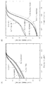
- FIG. 2 shows an example of the relationship between voltage and current density obtained by the rotating ring disk electrode method.
- FIG. 2A shows the results for four types of Pc / Co catalysts
- FIG. 2B shows the results for four types of PVP / Fe / KB catalysts, Q / Co / KB catalysts, and Q-Ph / Co / KB catalysts. Results are shown.
- the horizontal axis represents voltage (V vs. NHE), and the vertical axis represents current density (mA / cm 2 ) at each voltage.
- a carbon catalyst in which a larger current flows at a higher voltage means that the performance as a catalyst is higher.
- FIG. 3 shows an example of the results of evaluating the current density (mA / cm 2 ), oxygen reduction initiation potential (V), and number of electrons involved in the reaction when 0.7 V is applied for each carbon catalyst. .
- the oxygen reduction activity of the carbon catalyst can be remarkably improved by subjecting the carbon catalyst to heat treatment. That is, for example, for Pc / Co (H400) that was heat-treated at 400 ° C., a current density about 5 times that of Pc / Co (N) that was not heat-treated was obtained. In addition, for Pc / Co (H700) that was heat-treated at 700 ° C., a current density about 30 times that of Pc / Co (N) that was not heat-treated was obtained. Furthermore, for Pc / Co (H1000) that was heat-treated at 1000 ° C., a current density about 42 times that of Pc / Co (N) that was not heat-treated was obtained.
- carbon catalysts that have been heat-treated at 700 ° C. or 1000 ° C. (PVP / Fe / KB (H700), PVP / Fe / KB (H1000)) are not subjected to heat treatment (PVP / An increase in current density of about 2.5 times that of (Fe / KB (N)) was confirmed.
- Example 5 In the same manner as in Example 1 described above, a raw material containing a polyvinylpyridine iron complex and ketjen black and containing 50% by weight of the ketjen black was obtained. Then, in the same manner as in Example 1 described above, this raw material was heated to raise the temperature, and held at 500 ° C., 600 ° C., 700 ° C., 800 ° C., 900 ° C. or 1000 ° C. for 1 hour in a nitrogen atmosphere.
- the composition thus obtained was pulverized and sieved, followed by metal removal treatment, and six types of carbon catalysts having different carbonization temperatures (PVP / Fe / KB ( C500), PVP / Fe / KB (C600), PVP / Fe / KB (C700), PVP / Fe / KB (C800), PVP / Fe / KB (C900), PVP / Fe / KB (C1000)) It was.
- Example 1 a part of the four types of carbon catalysts produced at a carbonization temperature of 700 ° C. to 1000 ° C. was subjected to heat treatment.
- the heating temperature in the heat treatment was 700 ° C.
- the oxygen reduction activity of each carbon catalyst was evaluated similarly to the above-mentioned Example 4.
- FIG. 4 shows four types of carbon catalysts produced at a carbonization temperature of 700 ° C. to 1000 ° C. and not subjected to heat treatment, and four types of catalysts produced at a carbonization temperature of 700 ° C. to 1000 ° C. and subjected to heat treatment.
- An example of the result of evaluating the oxygen reduction starting potential (V) and the number of electrons involved in the reaction is shown. As shown in FIG. 4, it was shown that the oxygen reduction activity of the carbon catalyst is improved by performing the heat treatment.
- Example 6 In the same manner as in Example 3 described above, two types of carbon catalysts (Pc / Co (C800) catalyst and Pc / Co (C1000) catalyst) carbonized at 800 ° C. or 1000 ° C. were obtained. Similarly, a carbon catalyst (Pc / Fe (C800) catalyst) carbonized at 800 ° C. was obtained by using an iron phthalocyanine complex instead of a cobalt phthalocyanine complex. And the oxygen reduction activity of each carbon catalyst was evaluated similarly to the above-mentioned Example 4.
- FIG. 5 shows an example of the results of evaluating the current density (mA / cm 2 ) and the oxygen reduction starting potential (V) when 0.7 V is applied for each carbon catalyst. As shown in FIG. 5, it was confirmed that each carbon catalyst has oxygen reduction activity.
- Example 7 Of the carbon catalysts obtained in Example 5 above, eight types of carbon catalysts, ketjen black used in the production of the carbon catalyst, and each of the three types of carbon catalysts obtained in Example 6 were crystallized. The distribution of the child size La was evaluated.
- a sample of the carbon catalyst was placed in a concave portion of a glass sample plate and pressed with a slide glass, and the concave portion was uniformly filled so that the surface thereof coincided with the reference surface.
- the glass sample plate was fixed to a wide-angle X-ray diffraction sample stage so that the shape of the filled carbon catalyst sample did not collapse.
- X-ray diffraction measurement was performed using an X-ray diffraction apparatus (Rigaku RINT2100 / PC, Rigaku Corporation).
- the applied voltage and current to the X-ray tube were 32 kV and 20 mA, respectively.
- the sampling interval was 0.1 °
- the scanning speed was 0.1 ° / min
- the measurement angle range (2 ⁇ ) was 5 to 100 °.
- CuK ⁇ was used as the incident X-ray.
- the procedure of the analysis method proposed by Diamond basically consists of (1) intensity measurement of 11 bands of a sample, (2) correction of measured intensity, and (3) model network surface expected to exist in the sample. (4) Calculation of theoretical scattering intensity from the assumed model network surface, (5) Least square fitting of the obtained measured intensity by the theoretical scattering intensity, (6) Model network surface from the weight of each theoretical scattering intensity It consists of six steps of calculating the weight fraction and average network surface size. Therefore, the data to be analyzed first was read and smoothed and absorbed. The smoothing process was performed 7 times, and the absorption correction was performed using the theoretical absorption coefficient 4.219.
- the two-dimensional lattice constant is generally set to a value between the lattice constants of benzene and ideal graphite, approximately 0.240 to 0.24612 nm.
- the Ruland coefficient indicates the integral width of the function representing the passband of the energy of the used monochromator, and generally takes a value of 0 to 1.
- 0.24412 nm was selected as an initial set value of the lattice constant a 0 as a value close to the lattice constant of a general carbonaceous material.
- 0.05 was selected as the default value of the coefficient of Rand.
- model network surface was selected.
- the theoretical strength can be calculated and executed using three types of model network surfaces: a benzene / coronene base model, a pyrene base model, and a mixed model.
- a benzene / coronene base model as shown in FIG. 6 was used.
- the scattering intensity of the model network surface (approximately 0.25 nm to 7 nm) having an odd multiple size (1, 3, 5... 25, 27, 29 times) of the two-dimensional lattice constant a 0 is calculated. Is possible.
- the crystallite size La distribution of 7.2 nm or less is 0.245 nm, 0.736 nm, 1.223 nm, 1.719 nm, 2.210 nm, 2.700 nm, 3.200 nm, 3.683 nm, 4.174 nm, Crystallite size percentages of 4.665 nm, 5.156 nm, 5.647 nm, 6.138 nm, 6.630 nm and 7.110 nm were obtained.
- FIG. 7 shows the crystallites obtained for each of the eight types of carbon catalysts produced in Example 5 above at a carbonization temperature of 700 to 1000 ° C. and the ketjen black used in the production of the carbon catalysts.
- An example of size La distribution is shown.
- 7A, C, E, and G show the results for carbon catalysts that were produced at carbonization temperatures of 700 ° C., 800 ° C., 900 ° C., and 1000 ° C. and were not heat treated, respectively
- FIGS. 7B, D, F, and H Show the results for carbon catalysts produced at carbonization temperatures of 700 ° C., 800 ° C., 900 ° C. and 1000 ° C. and heat treated at 700 ° C., respectively
- FIG. 7I shows the results for Ketjen Black.
- FIG. 8 shows an example of the distribution of crystallite size La obtained for the three types of carbon catalysts obtained in Example 6 described above.
- FIGS. 8A, B, and C show the results for the Pc / Co (C800) catalyst, the Pc / Co (C1000) catalyst, and the Pc / Fe (C800) catalyst that were not heat treated, respectively.
- FIG. 9 shows the ratio (%) of the crystallite size La in each range in the crystallite size La distribution obtained for the 13 types of carbon catalysts and ketjen black that were analyzed.
- the heat-treated PVP / Fe / KB catalyst has a high ratio of crystallite size La in the range of 2 to 5 nm as high as 80 to 100% and a ratio of less than 2 nm as low as 10% or less. It had a characteristic crystallite size La distribution.
- the PVP / Fe / KB catalyst subjected to the heat treatment has a unique crystal structure in which the ratio of the crystallite size La within the range of 3 to 5 nm is as high as 70% or more and the ratio of less than 3 nm is as low as 20% or less. It had a child size La distribution.
Landscapes
- Chemical & Material Sciences (AREA)
- Chemical Kinetics & Catalysis (AREA)
- Electrochemistry (AREA)
- General Chemical & Material Sciences (AREA)
- Organic Chemistry (AREA)
- Inorganic Chemistry (AREA)
- Engineering & Computer Science (AREA)
- Manufacturing & Machinery (AREA)
- Catalysts (AREA)
- Inert Electrodes (AREA)
- Carbon And Carbon Compounds (AREA)
- Materials Engineering (AREA)
Abstract
Description
1.5gのビニルピリジンを20mLのジメチルホルムアミドに溶解させた後、70℃で5日間かけて高分子化を行い、ポリビニルピリジンを得た。このポリビニルピリジンに0.65gの塩化鉄六水和物を加え、室温で24時間攪拌することによりポリビニルピリジン鉄錯体を得た。
10gの8-キノリノール(オキシン)と、10gのホルムアルデヒドと、1gのシュウ酸二水和物を容積100mLのナスフラスコに入れ、100℃で一晩還流させた。次いで、1MのHClを5.5mL加え、同様に一晩還流させた。得られた固体を吸引ろ過し、蒸留水で3回洗浄し、一晩真空乾燥させて、高分子(Q高分子)を得た。
300mLのアセトンに3.275gのフェノ-ル樹脂(群栄化学工業株式会社)を加え、超音波を照射して溶解させた。さらに、1.0gのコバルトフタロシアニン錯体(東京化成工業株式会社)を加え、超音波を照射しながらロ-タリ-エバポレ-タ-を用いて40℃で溶媒を除去した。その後、残された組成物を温度80℃で24時間真空乾燥することにより、フェノ-ル樹脂を含有するコバルトフタロシアニン錯体を合成した。
実施例1で得られた5種類の炭素触媒、実施例2で得られた2種類の炭素触媒、実施例3で得られた4種類の炭素触媒のそれぞれについて、酸素還元活性を評価した。すなわち、まず、粉末状の炭素触媒を5mg量り取り、これに50μLのバインダー溶液(ナフィオン(登録商標)、デュポン株式会社)、150μLの水、150μLのエタノールを適量加え、この混合溶液を触媒スラリーとして調製した。

上述の実施例1と同様にして、ポリビニルピリジン鉄錯体とケッチェンブラックとを含有し、当該ケッチェンブラックを50重量%含有する原料を得た。そして、上述の実施例1と同様に、この原料を加熱して昇温し、窒素雰囲気下、500℃、600℃、700℃、800℃、900℃又は1000℃で1時間保持した。
上述の実施例3と同様にして、800℃又は1000℃で炭素化された2種類の炭素触媒(Pc/Co(C800)触媒、Pc/Co(C1000)触媒)を得た。また、同様に、コバルトフタロシアニン錯体に代えて、鉄フタロシアニン錯体を用いることにより、800℃で炭素化された炭素触媒(Pc/Fe(C800)触媒)を得た。そして、上述の実施例4と同様に、各炭素触媒の酸素還元活性を評価した。
上述の実施例5で得られた炭素触媒のうち8種類の炭素触媒、当該炭素触媒の製造に用いられたケッチェンブラック、及び実施例6で得られた3種類の炭素触媒の各々について、結晶子サイズLaの分布を評価した。


Claims (13)
- 炭素構造を有し、
前記炭素構造を構成する炭素網面の7.2nm以下の結晶子サイズLa分布において、1~5nmの割合が10%以上であり、5nmを超える割合が60%以下である
ことを特徴とする炭素触媒。 - 炭素構造を有し、
前記炭素構造を構成する炭素網面の7.2nm以下の結晶子サイズLa分布において、1~5nmの割合が10%以上であり、且つ1nm未満の割合が70%以下である
ことを特徴とする炭素触媒。 - 前記結晶子サイズLa分布において、2~5nmの割合が80%以上であり、2nm未満の割合が10%以下である
ことを特徴とする請求項1又は2に記載された炭素触媒。 - 前記結晶子サイズLa分布において、3~5nmの割合が70%以上であり、3nm未満の割合が20%以下である
ことを特徴とする請求項1乃至3のいずれかに記載された炭素触媒。 - 前記炭素構造は、樹脂と金属とを含有する原料を加熱して炭素化することにより形成された炭素構造である
ことを特徴とする請求項1乃至4のいずれかに記載された炭素触媒。 - 請求項1乃至5のいずれかに記載された炭素触媒が担持されている
ことを特徴とする電極。 - 請求項6に記載された電極を有する
ことを特徴とする電池。 - 樹脂と金属とを含有する原料を加熱して炭素化することにより炭素触媒を得る第一工程と、
前記炭素触媒に前記金属を除去する処理を施す第二工程と、
前記処理が施された前記炭素触媒に熱処理を施すことにより前記炭素触媒の活性を向上させる第三工程と、
を含む
ことを特徴とする炭素触媒の製造方法。 - 前記熱処理は、300~1500℃の範囲内の温度で前記炭素触媒を加熱することにより行う
ことを特徴とする請求項8に記載された炭素触媒の製造方法。 - 前記熱処理は、前記第一工程で前記原料を加熱した温度以下の温度で前記炭素触媒を加熱することにより行う
ことを特徴とする請求項8又は9に記載された炭素触媒の製造方法。 - 前記第二工程において、酸を用いて前記炭素触媒を洗浄することにより、前記炭素触媒に前記処理を施す
ことを特徴とする請求項8乃至10のいずれかに記載された炭素触媒の製造方法。 - 前記金属は遷移金属である
ことを特徴とする請求項8乃至11のいずれかに記載された炭素触媒の製造方法。 - 請求項8乃至12のいずれかに記載された方法により製造された
ことを特徴とする炭素触媒。
Priority Applications (5)
| Application Number | Priority Date | Filing Date | Title |
|---|---|---|---|
| EP09830322.5A EP2371448B1 (en) | 2008-12-02 | 2009-11-24 | Carbon catalyst, method for manufacturing the carbon catalyst, and electrode and battery using the carbon catalyst |
| US13/131,997 US9059471B2 (en) | 2008-12-02 | 2009-11-24 | Carbon catalyst, method for manufacturing the carbon catalyst, and electrode and battery using the carbon catalyst |
| JP2010541294A JP4979816B2 (ja) | 2008-12-02 | 2009-11-24 | 炭素触媒及びその製造方法、これを用いた電極及び電池 |
| CA2745108A CA2745108C (en) | 2008-12-02 | 2009-11-24 | Carbon catalyst, method for manufacturing the carbon catalyst, and electrode and battery using the carbon catalyst |
| US14/706,592 US9548499B2 (en) | 2008-12-02 | 2015-05-07 | Carbon catalyst, method for manufacturing the carbon catalyst, and electrode and battery using the carbon catalyst |
Applications Claiming Priority (2)
| Application Number | Priority Date | Filing Date | Title |
|---|---|---|---|
| JP2008-307847 | 2008-12-02 | ||
| JP2008307847 | 2008-12-02 |
Related Child Applications (2)
| Application Number | Title | Priority Date | Filing Date |
|---|---|---|---|
| US13/131,997 A-371-Of-International US9059471B2 (en) | 2008-12-02 | 2009-11-24 | Carbon catalyst, method for manufacturing the carbon catalyst, and electrode and battery using the carbon catalyst |
| US14/706,592 Division US9548499B2 (en) | 2008-12-02 | 2015-05-07 | Carbon catalyst, method for manufacturing the carbon catalyst, and electrode and battery using the carbon catalyst |
Publications (1)
| Publication Number | Publication Date |
|---|---|
| WO2010064555A1 true WO2010064555A1 (ja) | 2010-06-10 |
Family
ID=42233206
Family Applications (1)
| Application Number | Title | Priority Date | Filing Date |
|---|---|---|---|
| PCT/JP2009/069777 Ceased WO2010064555A1 (ja) | 2008-12-02 | 2009-11-24 | 炭素触媒及びその製造方法、これを用いた電極及び電池 |
Country Status (5)
| Country | Link |
|---|---|
| US (2) | US9059471B2 (ja) |
| EP (1) | EP2371448B1 (ja) |
| JP (1) | JP4979816B2 (ja) |
| CA (1) | CA2745108C (ja) |
| WO (1) | WO2010064555A1 (ja) |
Cited By (16)
| Publication number | Priority date | Publication date | Assignee | Title |
|---|---|---|---|---|
| JP2010275115A (ja) * | 2009-05-26 | 2010-12-09 | Teijin Ltd | 炭素材料及びその製造方法 |
| JP2010275116A (ja) * | 2009-05-26 | 2010-12-09 | Teijin Ltd | 炭素材料及びその製造方法 |
| JP2012054157A (ja) * | 2010-09-02 | 2012-03-15 | Kyushu Univ | 炭素触媒 |
| JP2012131972A (ja) * | 2010-08-30 | 2012-07-12 | Sumitomo Chemical Co Ltd | ポリマーコンポジット変性物 |
| JP2012146670A (ja) * | 2010-07-15 | 2012-08-02 | Showa Denko Kk | 燃料電池用触媒およびその用途 |
| JP2013043821A (ja) * | 2011-08-26 | 2013-03-04 | Asahi Kasei Chemicals Corp | 窒素含有炭素材料、その製造方法及び燃料電池用電極 |
| JP2013109896A (ja) * | 2011-11-18 | 2013-06-06 | Toyota Motor Corp | 電極材料及び電極材料の製造方法 |
| EP2682366A4 (en) * | 2011-02-28 | 2014-08-27 | Japan Science & Tech Agency | METHOD FOR THE PRODUCTION OF GRAPHES, GRAPHS MADE ON A SUBSTRATE, AND GRAPHS ON THE SUBSTRATE |
| US20140339097A1 (en) * | 2011-03-24 | 2014-11-20 | Kabushiki Kaisha Toshiba | Electrolysis device and refrigerator |
| WO2014208740A1 (ja) * | 2013-06-28 | 2014-12-31 | 富士フイルム株式会社 | 含窒素カーボンアロイの製造方法、含窒素カーボンアロイ及び燃料電池触媒 |
| WO2015146858A1 (ja) * | 2014-03-27 | 2015-10-01 | イハラケミカル工業株式会社 | 電極触媒及びその製造方法 |
| WO2015147131A1 (ja) * | 2014-03-28 | 2015-10-01 | 国立大学法人群馬大学 | カーボンアロイ触媒の製造方法、カーボンアロイ触媒 |
| WO2017209244A1 (ja) * | 2016-06-02 | 2017-12-07 | 日清紡ホールディングス株式会社 | 炭素触媒、電池電極及び電池 |
| JP2019532889A (ja) * | 2016-08-30 | 2019-11-14 | ナノテク インストゥルメンツ, インコーポレイテッドNanotek Instruments, Inc. | 高導電性黒鉛フィルムおよび製造方法 |
| WO2024116714A1 (ja) * | 2022-11-29 | 2024-06-06 | 日清紡ホールディングス株式会社 | 炭素触媒、電極及び電池 |
| WO2024116715A1 (ja) * | 2022-11-29 | 2024-06-06 | 日清紡ホールディングス株式会社 | 炭素触媒、電極及び電池 |
Families Citing this family (20)
| Publication number | Priority date | Publication date | Assignee | Title |
|---|---|---|---|---|
| WO2010064555A1 (ja) | 2008-12-02 | 2010-06-10 | 日清紡ホールディングス株式会社 | 炭素触媒及びその製造方法、これを用いた電極及び電池 |
| WO2010064556A1 (ja) | 2008-12-02 | 2010-06-10 | 日清紡ホールディングス株式会社 | 炭素触媒及びその製造方法、これを用いた電極及び電池 |
| WO2014020915A1 (ja) * | 2012-08-01 | 2014-02-06 | 東洋インキScホールディングス株式会社 | 電池触媒用組成物及びその製造方法、電極材料、並びに燃料電池 |
| JP6241318B2 (ja) * | 2014-02-28 | 2017-12-06 | 富士通株式会社 | グラフェン膜の製造方法及び半導体装置の製造方法 |
| US20160059444A1 (en) * | 2014-08-29 | 2016-03-03 | Yanbo Wang | Production of highly conductive graphitic films from polymer films |
| US10381643B2 (en) | 2014-10-08 | 2019-08-13 | Energizer Brands, Llc | Fluorosurfactant as a zinc corrosion inhibitor |
| US10205206B2 (en) | 2014-10-08 | 2019-02-12 | Energizer Brands, Llc | Zinc-air electrochemical cell |
| WO2016065230A1 (en) | 2014-10-23 | 2016-04-28 | Energizer Brands, Llc | Zinc anode composition |
| CN104979568A (zh) * | 2015-05-12 | 2015-10-14 | 北京化工大学 | 一种燃料电池阴极催化剂及其制备方法 |
| US10332693B2 (en) | 2016-07-15 | 2019-06-25 | Nanotek Instruments, Inc. | Humic acid-based supercapacitors |
| US11254616B2 (en) | 2016-08-04 | 2022-02-22 | Global Graphene Group, Inc. | Method of producing integral 3D humic acid-carbon hybrid foam |
| US10731931B2 (en) | 2016-08-18 | 2020-08-04 | Global Graphene Group, Inc. | Highly oriented humic acid films and highly conducting graphitic films derived therefrom and devices containing same |
| US10014519B2 (en) | 2016-08-22 | 2018-07-03 | Nanotek Instruments, Inc. | Process for producing humic acid-bonded metal foil film current collector |
| US10597389B2 (en) | 2016-08-22 | 2020-03-24 | Global Graphene Group, Inc. | Humic acid-bonded metal foil film current collector and battery and supercapacitor containing same |
| US10593932B2 (en) | 2016-09-20 | 2020-03-17 | Global Graphene Group, Inc. | Process for metal-sulfur battery cathode containing humic acid-derived conductive foam |
| US10647595B2 (en) | 2016-08-30 | 2020-05-12 | Global Graphene Group, Inc. | Humic acid-derived conductive foams and devices |
| US10584216B2 (en) | 2016-08-30 | 2020-03-10 | Global Graphene Group, Inc. | Process for producing humic acid-derived conductive foams |
| US12060273B2 (en) | 2020-04-21 | 2024-08-13 | Global Graphene Group, Inc. | Production of graphitic films from a mixture of graphene oxide and highly aromatic molecules |
| CN114653373B (zh) * | 2022-05-10 | 2023-04-04 | 中国矿业大学 | 一种高选择性镍树脂碳催化剂及其制备方法与应用 |
| CN117069105B (zh) * | 2023-09-18 | 2025-09-02 | 成都理工大学 | 钠离子电池用负极材料及其制备方法、钠离子电池 |
Citations (4)
| Publication number | Priority date | Publication date | Assignee | Title |
|---|---|---|---|---|
| JP2007018801A (ja) * | 2005-07-06 | 2007-01-25 | Gs Yuasa Corporation:Kk | 固体高分子形燃料電池用触媒混合体の製造方法およびその製造方法で得られた触媒混合体を含む電極を用いた固体高分子形燃料電池 |
| JP2007026746A (ja) | 2005-07-13 | 2007-02-01 | Gunma Univ | 燃料電池用電極触媒の製造方法及びその方法で製造された電極触媒並びにその電極触媒を用いた燃料電池 |
| JP2007207662A (ja) | 2006-02-03 | 2007-08-16 | Gunma Univ | 燃料電池用電極触媒及びその製造方法並びに該触媒を用いた燃料電池 |
| JP2008282725A (ja) | 2007-05-11 | 2008-11-20 | Gunma Univ | 炭素系燃料電池用電極触媒の製造方法 |
Family Cites Families (14)
| Publication number | Priority date | Publication date | Assignee | Title |
|---|---|---|---|---|
| US4756898A (en) * | 1987-04-30 | 1988-07-12 | The United States Of America As Represented By The United States Department Of Energy | Low density microcellular carbon or catalytically impregnated carbon foams and process for their prepartion |
| JP3544237B2 (ja) * | 1995-02-09 | 2004-07-21 | 独立行政法人 科学技術振興機構 | 巨大フラーレンの製造方法 |
| JPH09249407A (ja) * | 1996-03-14 | 1997-09-22 | Toyota Central Res & Dev Lab Inc | 黒鉛複合物およびその製造方法 |
| JP3601581B2 (ja) * | 1999-06-11 | 2004-12-15 | 東洋紡績株式会社 | バナジウム系レドックスフロー電池用炭素電極材 |
| US7816037B2 (en) | 2002-01-25 | 2010-10-19 | Toyo Tanso Co., Ltd. | Anode material for lithium ion secondary battery |
| JP3837076B2 (ja) | 2002-02-26 | 2006-10-25 | 純一 尾崎 | 燃料電池用電極触媒及びそれを用いた燃料電池 |
| JP3969658B2 (ja) | 2003-06-27 | 2007-09-05 | 純一 尾崎 | 燃料電池用電極触媒、それを用いた燃料電池および電極 |
| WO2006046656A1 (ja) | 2004-10-28 | 2006-05-04 | Mitsubishi Chemical Corporation | 球状炭素粒子およびその集合体 |
| US8114803B2 (en) | 2005-02-03 | 2012-02-14 | Toyota Jidosha Kabushiki Kaisha | Catalyst material and process for preparing the same |
| US7887771B2 (en) * | 2005-10-06 | 2011-02-15 | Headwaters Technology Innovation, Llc | Carbon nanorings manufactured from templating nanoparticles |
| US7718155B2 (en) * | 2005-10-06 | 2010-05-18 | Headwaters Technology Innovation, Llc | Carbon nanostructures manufactured from catalytic templating nanoparticles |
| AU2007217054A1 (en) | 2006-02-17 | 2007-08-30 | Monsanto Technology Llc | Transition metal-containing catalysts and processes for their preparation and use as fuel cell catalysts |
| JP2008173606A (ja) | 2007-01-22 | 2008-07-31 | Toyota Motor Corp | 触媒材料及びその製造方法 |
| WO2010064555A1 (ja) | 2008-12-02 | 2010-06-10 | 日清紡ホールディングス株式会社 | 炭素触媒及びその製造方法、これを用いた電極及び電池 |
-
2009
- 2009-11-24 WO PCT/JP2009/069777 patent/WO2010064555A1/ja not_active Ceased
- 2009-11-24 US US13/131,997 patent/US9059471B2/en active Active
- 2009-11-24 CA CA2745108A patent/CA2745108C/en active Active
- 2009-11-24 EP EP09830322.5A patent/EP2371448B1/en not_active Not-in-force
- 2009-11-24 JP JP2010541294A patent/JP4979816B2/ja active Active
-
2015
- 2015-05-07 US US14/706,592 patent/US9548499B2/en active Active
Patent Citations (4)
| Publication number | Priority date | Publication date | Assignee | Title |
|---|---|---|---|---|
| JP2007018801A (ja) * | 2005-07-06 | 2007-01-25 | Gs Yuasa Corporation:Kk | 固体高分子形燃料電池用触媒混合体の製造方法およびその製造方法で得られた触媒混合体を含む電極を用いた固体高分子形燃料電池 |
| JP2007026746A (ja) | 2005-07-13 | 2007-02-01 | Gunma Univ | 燃料電池用電極触媒の製造方法及びその方法で製造された電極触媒並びにその電極触媒を用いた燃料電池 |
| JP2007207662A (ja) | 2006-02-03 | 2007-08-16 | Gunma Univ | 燃料電池用電極触媒及びその製造方法並びに該触媒を用いた燃料電池 |
| JP2008282725A (ja) | 2007-05-11 | 2008-11-20 | Gunma Univ | 炭素系燃料電池用電極触媒の製造方法 |
Non-Patent Citations (8)
| Title |
|---|
| "Abstracts of Annual Meeting of the Carbon Society of Japan, 28 November 2008 (28. 11.2008)", vol. 35TH, article RIEKO KOBAYASHI ET AL.: "PVP Kinzoku Sakutai o Mochiita Tansokei Shokubai ni Okeru Tanso Tantai no Hyomen Jotai ga Sanso Kangen Kassei e Oyobosu Eikyo", pages: 124 - 125, XP008169391 * |
| HIROYUKI FUJIMOTO, CARBON, vol. 192, 2000, pages 125 - 129 |
| HIROYUKI FUJIMOTO, CARBON, vol. 228, 2007, pages 185 - 194 |
| R. DIAMOND, ACTA. CRYST., vol. 10, 1957, pages 359 - 363 |
| R. DIAMOND, ACTA. CRYST., vol. 11, 1958, pages 129 - 138 |
| R. DIAMOND, PH.D. DISSERTATION, 1956 |
| R. DIAMOND, PHIL. TRANS. ROY. SOC. LONDON, vol. A252, 1960, pages 193 - 223 |
| See also references of EP2371448A4 |
Cited By (24)
| Publication number | Priority date | Publication date | Assignee | Title |
|---|---|---|---|---|
| JP2010275115A (ja) * | 2009-05-26 | 2010-12-09 | Teijin Ltd | 炭素材料及びその製造方法 |
| JP2010275116A (ja) * | 2009-05-26 | 2010-12-09 | Teijin Ltd | 炭素材料及びその製造方法 |
| JP2012146670A (ja) * | 2010-07-15 | 2012-08-02 | Showa Denko Kk | 燃料電池用触媒およびその用途 |
| JP2012131972A (ja) * | 2010-08-30 | 2012-07-12 | Sumitomo Chemical Co Ltd | ポリマーコンポジット変性物 |
| JP2016029183A (ja) * | 2010-08-30 | 2016-03-03 | 住友化学株式会社 | ポリマーコンポジット変性物 |
| JP2012054157A (ja) * | 2010-09-02 | 2012-03-15 | Kyushu Univ | 炭素触媒 |
| EP2682366A4 (en) * | 2011-02-28 | 2014-08-27 | Japan Science & Tech Agency | METHOD FOR THE PRODUCTION OF GRAPHES, GRAPHS MADE ON A SUBSTRATE, AND GRAPHS ON THE SUBSTRATE |
| US9863047B2 (en) * | 2011-03-24 | 2018-01-09 | Toshiba Lifestyle Products & Services Corporation | Electrolysis device and refrigerator |
| US20140339097A1 (en) * | 2011-03-24 | 2014-11-20 | Kabushiki Kaisha Toshiba | Electrolysis device and refrigerator |
| JP2013043821A (ja) * | 2011-08-26 | 2013-03-04 | Asahi Kasei Chemicals Corp | 窒素含有炭素材料、その製造方法及び燃料電池用電極 |
| JP2013109896A (ja) * | 2011-11-18 | 2013-06-06 | Toyota Motor Corp | 電極材料及び電極材料の製造方法 |
| JP2015027934A (ja) * | 2013-06-28 | 2015-02-12 | 富士フイルム株式会社 | 含窒素カーボンアロイの製造方法、含窒素カーボンアロイ及び燃料電池触媒 |
| WO2014208740A1 (ja) * | 2013-06-28 | 2014-12-31 | 富士フイルム株式会社 | 含窒素カーボンアロイの製造方法、含窒素カーボンアロイ及び燃料電池触媒 |
| WO2015146858A1 (ja) * | 2014-03-27 | 2015-10-01 | イハラケミカル工業株式会社 | 電極触媒及びその製造方法 |
| JPWO2015146858A1 (ja) * | 2014-03-27 | 2017-04-13 | イハラケミカル工業株式会社 | 電極触媒及びその製造方法 |
| US10193162B2 (en) | 2014-03-27 | 2019-01-29 | Kumiai Chemical Industry Co., Ltd. | Electrode catalyst and method for producing the same |
| WO2015147131A1 (ja) * | 2014-03-28 | 2015-10-01 | 国立大学法人群馬大学 | カーボンアロイ触媒の製造方法、カーボンアロイ触媒 |
| WO2017209244A1 (ja) * | 2016-06-02 | 2017-12-07 | 日清紡ホールディングス株式会社 | 炭素触媒、電池電極及び電池 |
| JPWO2017209244A1 (ja) * | 2016-06-02 | 2019-03-28 | 日清紡ホールディングス株式会社 | 炭素触媒、電池電極及び電池 |
| US11114672B2 (en) | 2016-06-02 | 2021-09-07 | Nisshinbo Holdings Inc. | Carbon catalyst, battery electrode, and battery |
| JP2019532889A (ja) * | 2016-08-30 | 2019-11-14 | ナノテク インストゥルメンツ, インコーポレイテッドNanotek Instruments, Inc. | 高導電性黒鉛フィルムおよび製造方法 |
| JP7030787B2 (ja) | 2016-08-30 | 2022-03-07 | ナノテク インストゥルメンツ,インコーポレイテッド | 高導電性黒鉛フィルムおよび製造方法 |
| WO2024116714A1 (ja) * | 2022-11-29 | 2024-06-06 | 日清紡ホールディングス株式会社 | 炭素触媒、電極及び電池 |
| WO2024116715A1 (ja) * | 2022-11-29 | 2024-06-06 | 日清紡ホールディングス株式会社 | 炭素触媒、電極及び電池 |
Also Published As
| Publication number | Publication date |
|---|---|
| US20110243830A1 (en) | 2011-10-06 |
| US9059471B2 (en) | 2015-06-16 |
| EP2371448B1 (en) | 2019-07-03 |
| EP2371448A4 (en) | 2016-11-23 |
| JP4979816B2 (ja) | 2012-07-18 |
| US9548499B2 (en) | 2017-01-17 |
| JPWO2010064555A1 (ja) | 2012-05-10 |
| EP2371448A1 (en) | 2011-10-05 |
| US20150244000A1 (en) | 2015-08-27 |
| CA2745108A1 (en) | 2010-06-10 |
| CA2745108C (en) | 2017-01-17 |
Similar Documents
| Publication | Publication Date | Title |
|---|---|---|
| JP4979816B2 (ja) | 炭素触媒及びその製造方法、これを用いた電極及び電池 | |
| JP4979817B2 (ja) | 炭素触媒及びその製造方法、これを用いた電極及び電池 | |
| US8993164B2 (en) | Support for catalyst supporting, carrier with supported catalyst, electrode, and battery | |
| CN103221129B (zh) | 碳催化剂及其制备方法、和各自装有该碳催化剂的电极和电池 | |
| JP5481646B2 (ja) | 炭素触媒、燃料電池、蓄電装置 | |
| CN106232226B (zh) | 碳催化剂、电极和电池 | |
| WO2011055739A1 (ja) | 炭素触媒並びにその製造方法及びこれを用いた電極並びに電池 | |
| JP5689379B2 (ja) | 触媒担持用担体、触媒担持体、電極及び電池 | |
| JP5732667B2 (ja) | 炭素触媒の製造方法 | |
| WO2009148116A1 (ja) | 炭素触媒及び炭素触媒の製造方法、燃料電池、蓄電装置、炭素触媒の使用方法 |
Legal Events
| Date | Code | Title | Description |
|---|---|---|---|
| 121 | Ep: the epo has been informed by wipo that ep was designated in this application |
Ref document number: 09830322 Country of ref document: EP Kind code of ref document: A1 |
|
| DPE1 | Request for preliminary examination filed after expiration of 19th month from priority date (pct application filed from 20040101) | ||
| WWE | Wipo information: entry into national phase |
Ref document number: 2745108 Country of ref document: CA |
|
| WWE | Wipo information: entry into national phase |
Ref document number: 13131997 Country of ref document: US |
|
| ENP | Entry into the national phase |
Ref document number: 2010541294 Country of ref document: JP Kind code of ref document: A |
|
| NENP | Non-entry into the national phase |
Ref country code: DE |
|
| WWE | Wipo information: entry into national phase |
Ref document number: 2009830322 Country of ref document: EP |