WO2010064565A1 - インバータ一体型電動圧縮機およびそのインバータ装置 - Google Patents
インバータ一体型電動圧縮機およびそのインバータ装置 Download PDFInfo
- Publication number
- WO2010064565A1 WO2010064565A1 PCT/JP2009/069918 JP2009069918W WO2010064565A1 WO 2010064565 A1 WO2010064565 A1 WO 2010064565A1 JP 2009069918 W JP2009069918 W JP 2009069918W WO 2010064565 A1 WO2010064565 A1 WO 2010064565A1
- Authority
- WO
- WIPO (PCT)
- Prior art keywords
- inverter
- electric compressor
- cpu
- integrated electric
- substrate
- Prior art date
- Legal status (The legal status is an assumption and is not a legal conclusion. Google has not performed a legal analysis and makes no representation as to the accuracy of the status listed.)
- Ceased
Links
Images



Classifications
-
- F—MECHANICAL ENGINEERING; LIGHTING; HEATING; WEAPONS; BLASTING
- F04—POSITIVE - DISPLACEMENT MACHINES FOR LIQUIDS; PUMPS FOR LIQUIDS OR ELASTIC FLUIDS
- F04B—POSITIVE-DISPLACEMENT MACHINES FOR LIQUIDS; PUMPS
- F04B39/00—Component parts, details, or accessories, of pumps or pumping systems specially adapted for elastic fluids, not otherwise provided for in, or of interest apart from, groups F04B25/00 - F04B37/00
- F04B39/12—Casings; Cylinders; Cylinder heads; Fluid connections
- F04B39/121—Casings
-
- F—MECHANICAL ENGINEERING; LIGHTING; HEATING; WEAPONS; BLASTING
- F04—POSITIVE - DISPLACEMENT MACHINES FOR LIQUIDS; PUMPS FOR LIQUIDS OR ELASTIC FLUIDS
- F04C—ROTARY-PISTON, OR OSCILLATING-PISTON, POSITIVE-DISPLACEMENT MACHINES FOR LIQUIDS; ROTARY-PISTON, OR OSCILLATING-PISTON, POSITIVE-DISPLACEMENT PUMPS
- F04C23/00—Combinations of two or more pumps, each being of rotary-piston or oscillating-piston type, specially adapted for elastic fluids; Pumping installations specially adapted for elastic fluids; Multi-stage pumps specially adapted for elastic fluids
- F04C23/008—Hermetic pumps
-
- H—ELECTRICITY
- H02—GENERATION; CONVERSION OR DISTRIBUTION OF ELECTRIC POWER
- H02K—DYNAMO-ELECTRIC MACHINES
- H02K11/00—Structural association of dynamo-electric machines with electric components or with devices for shielding, monitoring or protection
- H02K11/30—Structural association with control circuits or drive circuits
- H02K11/33—Drive circuits, e.g. power electronics
-
- H—ELECTRICITY
- H02—GENERATION; CONVERSION OR DISTRIBUTION OF ELECTRIC POWER
- H02M—APPARATUS FOR CONVERSION BETWEEN AC AND AC, BETWEEN AC AND DC, OR BETWEEN DC AND DC, AND FOR USE WITH MAINS OR SIMILAR POWER SUPPLY SYSTEMS; CONVERSION OF DC OR AC INPUT POWER INTO SURGE OUTPUT POWER; CONTROL OR REGULATION THEREOF
- H02M7/00—Conversion of AC power input into DC power output; Conversion of DC power input into AC power output
- H02M7/003—Constructional details, e.g. physical layout, assembly, wiring or busbar connections
-
- H—ELECTRICITY
- H05—ELECTRIC TECHNIQUES NOT OTHERWISE PROVIDED FOR
- H05K—PRINTED CIRCUITS; CASINGS OR CONSTRUCTIONAL DETAILS OF ELECTRIC APPARATUS; MANUFACTURE OF ASSEMBLAGES OF ELECTRICAL COMPONENTS
- H05K1/00—Printed circuits
- H05K1/02—Details
- H05K1/0201—Thermal arrangements, e.g. for cooling, heating or preventing overheating
-
- H—ELECTRICITY
- H05—ELECTRIC TECHNIQUES NOT OTHERWISE PROVIDED FOR
- H05K—PRINTED CIRCUITS; CASINGS OR CONSTRUCTIONAL DETAILS OF ELECTRIC APPARATUS; MANUFACTURE OF ASSEMBLAGES OF ELECTRICAL COMPONENTS
- H05K5/00—Casings, cabinets or drawers for electric apparatus
- H05K5/02—Details
- H05K5/0247—Electrical details of casings, e.g. terminals, passages for cables or wiring
-
- H—ELECTRICITY
- H05—ELECTRIC TECHNIQUES NOT OTHERWISE PROVIDED FOR
- H05K—PRINTED CIRCUITS; CASINGS OR CONSTRUCTIONAL DETAILS OF ELECTRIC APPARATUS; MANUFACTURE OF ASSEMBLAGES OF ELECTRICAL COMPONENTS
- H05K7/00—Constructional details common to different types of electric apparatus
- H05K7/14—Mounting supporting structure in casing or on frame or rack
- H05K7/1422—Printed circuit boards receptacles, e.g. stacked structures, electronic circuit modules or box like frames
- H05K7/1427—Housings
- H05K7/1432—Housings specially adapted for power drive units or power converters
- H05K7/14322—Housings specially adapted for power drive units or power converters wherein the control and power circuits of a power converter are arranged within the same casing
-
- H—ELECTRICITY
- H10—SEMICONDUCTOR DEVICES; ELECTRIC SOLID-STATE DEVICES NOT OTHERWISE PROVIDED FOR
- H10W—GENERIC PACKAGES, INTERCONNECTIONS, CONNECTORS OR OTHER CONSTRUCTIONAL DETAILS OF DEVICES COVERED BY CLASS H10
- H10W90/00—Package configurations
-
- F—MECHANICAL ENGINEERING; LIGHTING; HEATING; WEAPONS; BLASTING
- F04—POSITIVE - DISPLACEMENT MACHINES FOR LIQUIDS; PUMPS FOR LIQUIDS OR ELASTIC FLUIDS
- F04B—POSITIVE-DISPLACEMENT MACHINES FOR LIQUIDS; PUMPS
- F04B2203/00—Motor parameters
- F04B2203/02—Motor parameters of rotating electric motors
- F04B2203/0204—Frequency of the electric current
-
- F—MECHANICAL ENGINEERING; LIGHTING; HEATING; WEAPONS; BLASTING
- F04—POSITIVE - DISPLACEMENT MACHINES FOR LIQUIDS; PUMPS FOR LIQUIDS OR ELASTIC FLUIDS
- F04C—ROTARY-PISTON, OR OSCILLATING-PISTON, POSITIVE-DISPLACEMENT MACHINES FOR LIQUIDS; ROTARY-PISTON, OR OSCILLATING-PISTON, POSITIVE-DISPLACEMENT PUMPS
- F04C2240/00—Components
- F04C2240/80—Other components
- F04C2240/808—Electronic circuits (e.g. inverters) installed inside the machine
-
- F—MECHANICAL ENGINEERING; LIGHTING; HEATING; WEAPONS; BLASTING
- F04—POSITIVE - DISPLACEMENT MACHINES FOR LIQUIDS; PUMPS FOR LIQUIDS OR ELASTIC FLUIDS
- F04C—ROTARY-PISTON, OR OSCILLATING-PISTON, POSITIVE-DISPLACEMENT MACHINES FOR LIQUIDS; ROTARY-PISTON, OR OSCILLATING-PISTON, POSITIVE-DISPLACEMENT PUMPS
- F04C2270/00—Control; Monitoring or safety arrangements
- F04C2270/12—Vibration
-
- H—ELECTRICITY
- H02—GENERATION; CONVERSION OR DISTRIBUTION OF ELECTRIC POWER
- H02K—DYNAMO-ELECTRIC MACHINES
- H02K7/00—Arrangements for handling mechanical energy structurally associated with dynamo-electric machines, e.g. structural association with mechanical driving motors or auxiliary dynamo-electric machines
- H02K7/14—Structural association with mechanical loads, e.g. with hand-held machine tools or fans
Definitions
- the present invention is an inverter-integrated electric compressor suitable for application to an in-vehicle air conditioner configured by integrating an inverter device on the outer periphery of a housing in which an electric motor and a compression mechanism are incorporated, and the inverter device. It is about.
- This inverter-integrated electric compressor is generally provided with an inverter accommodating portion (inverter box) on the outer periphery of a housing in which an electric motor and a compression mechanism are built, and DC power supplied from a high-voltage power source is three inside.
- An inverter device that converts to phase AC power and supplies power to the electric motor through a glass sealed terminal is incorporated.
- an inverter device is a power system board (pedestal part, unit) on which a plurality of power semiconductor switching elements (IGBT or the like) for converting DC power into three-phase AC power are mounted.
- a power system board (pedestal part, unit) on which a plurality of power semiconductor switching elements (IGBT or the like) for converting DC power into three-phase AC power are mounted.
- a base and a CPU board (printed board) on which a control communication circuit having an element that operates at a low voltage such as a CPU is mounted in two upper and lower stages, and this is accommodated in an inverter case or an outer frame part.
- a control communication circuit having an element that operates at a low voltage such as a CPU is mounted in two upper and lower stages, and this is accommodated in an inverter case or an outer frame part.
- Patent Documents 1 and 2 include ones in which an inverter housing in which an inverter device is incorporated is filled with a gel-like resin material such as silicon gel, or a CPU substrate is floated and installed in a gel-like resin material. Proposed.
- Patent Document 3 a three-layered board of a metal board, a control board and an interface board is arranged in a resin case in a hierarchical manner, and the power semiconductor surface of the metal board is filled with a gel material and controlled from the surface. There has been proposed a resin-encapsulated material up to the top surface of the substrate.
- the present invention has been made in view of such circumstances, and is an inverter that can sufficiently secure vibration resistance with respect to the CPU board installed on the upper surface of the inverter module and can reduce the weight of the inverter device.
- An object is to provide an integrated electric compressor and an inverter device thereof.
- the inverter-integrated electric compressor and the inverter device thereof according to the present invention employ the following means. That is, the inverter-integrated electric compressor according to one aspect of the present invention is provided with an inverter housing portion on the outer periphery of a housing in which the electric motor and the compression mechanism are built, and DC power from a high-voltage power source is supplied to the inside.
- the inverter device includes a power metal substrate on which a semiconductor switching element or the like is mounted, and a plurality of A CPU board is provided that includes an inverter module integrated with a resin case in which terminals and the like are integrally molded, and a control communication circuit that operates at a low voltage such as a CPU is mounted on the upper surface of the inverter module.
- the resin case is insulated and covered so as to cover the upper surface of the power metal substrate.
- a moisture thermosetting resin layer is provided, and between the lower surface of the CPU substrate and the thermosetting resin layer, a vibration absorbing material that maintains a rubber state in the operating temperature range of the electric compressor.
- An elastic resin adhesive layer is provided.
- the insulating and moisture-proof thermosetting resin layer is provided in the resin case of the inverter module so as to cover the upper surface of the power metal substrate, and is provided on the upper surface of the inverter module.
- a vibration-absorbing elastic resin adhesive layer that maintains a rubber state in the operating temperature range of the electric compressor is provided. For this reason, the semiconductor switching element mounted on the power metal substrate is firmly secured and protected by the thermosetting resin layer covering the upper surface, and the leading edge and moisture resistance of the power metal substrate to which a high voltage is applied.
- the vibration force applied to the CPU board is absorbed by the elastic resin adhesive layer provided on the lower surface of the CPU board, so that the CPU board can be prevented from damaging or dropping off components on the board. Can do. Therefore, by providing two resin layers suitable for protecting the power metal substrate and the CPU substrate in the resin case of the inverter module, respectively, the two substrates can be appropriately protected with a small amount of resin, and the vibration resistance can be prevented. The reliability of the inverter device can be increased, and the weight of the inverter-integrated electric compressor can be reduced.
- the inverter-integrated electric compressor is the inverter-integrated electric compressor, wherein the elastic resin adhesive layer is provided on a central portion of the CPU board or on the CPU board. It is good also as providing only corresponding to specific parts, such as a lower part of heavy parts, such as a transformer and an electrolytic capacitor which are present.
- the elastic resin adhesive layer is provided corresponding to only a specific part such as a central part of the CPU board or a lower part of a heavy component such as a transformer or an electrolytic capacitor provided on the CPU board. Therefore, the vibration of the CPU board is absorbed through the elastic resin adhesive layer in the central part of the CPU board that is particularly prone to vibration and the lower part of heavy parts such as transformers and electrolytic capacitors provided on the CPU board. be able to. Therefore, it is possible to effectively suppress the vibration of the CPU board while suppressing the amount of the elastic resin adhesive used, and to reduce the weight and cost of the inverter device accordingly.
- the inverter-integrated electric compressor according to one aspect of the present invention is the inverter-integrated electric compressor, in which the elastic resin adhesive layer is between the lower surface of the CPU board and the thermosetting resin layer. It may be provided over almost the entire surface.
- the elastic resin adhesive layer is provided over almost the entire surface between the lower surface of the CPU substrate and the thermosetting resin layer, the entire lower surface of the CPU substrate is supported by the elastic resin adhesive layer.
- the vibration can be absorbed.
- the usage amount of the elastic resin adhesive is somewhat increased, priority can be given to the vibration reduction of the CPU substrate, and the vibration resistance of the inverter device can be further improved.
- thermosetting resin layer may be made of an epoxy resin.
- thermosetting resin layer is composed of the epoxy resin
- the mounting component on the power metal substrate is covered with the thermosetting epoxy resin layer having excellent insulation and moisture resistance. (Enclosed) can be firmly fixed and protected. Therefore, it is possible to sufficiently ensure the insulating property, moisture proof property, and vibration resistance of the power metal substrate on which the semiconductor switching element or the like is mounted.
- the elastic resin adhesive layer is formed of a silicon-based resin adhesive. Also good.
- the elastic resin adhesive layer is composed of the silicon-based resin adhesive
- the lower surface of the CPU substrate has excellent heat resistance and elasticity in a wide temperature range from a low temperature range to a high temperature range. It can be elastically supported by the silicon-based resin adhesive layer to absorb the excitation force applied to the CPU substrate. Therefore, it is possible to reliably prevent damage and dropout of components on the substrate due to vibration of the CPU substrate, and greatly improve the vibration resistance of the inverter device.
- the inverter-integrated electric compressor according to one aspect of the present invention is the above-described inverter-integrated electric compressor, wherein the silicon-based resin adhesive has a glass transition point of ⁇ 40 ° C. or lower. Also good.
- the glass transition point of the silicon-based resin adhesive constituting the elastic resin adhesive layer is set to ⁇ 40 ° C. or lower, it is necessary to be able to be used even in a low temperature environment of about ⁇ 40 ° C. Even when applied to an in-vehicle inverter-integrated electric compressor, the elastic resin adhesive layer can maintain a rubber state and elastically support the CPU substrate. Therefore, a sufficient vibration absorbing effect can be obtained even in a cryogenic environment.
- an inverter device is a modularized inverter device that is integrated into an inverter-integrated electric compressor, and the inverter device is a power system in which a semiconductor switching element or the like is mounted.
- An inverter module in which a metal substrate and a resin case in which a plurality of terminals are integrally formed by insert molding is integrated, and a control communication circuit that operates at a low voltage such as a CPU is mounted on the upper surface of the inverter module.
- an insulating and moisture-proof thermosetting resin layer is provided so as to cover the upper surface of the power metal substrate, and the CPU substrate is provided.
- an elastic resin adhesive layer is provided for vibration absorption that maintains a rubber state in the operating temperature range of the electric compressor between the lower surface of the thermosetting resin layer and the thermosetting resin layer May be an elastic resin adhesive layer is provided.
- the insulating and moisture-proof thermosetting resin layer is provided in the resin case of the inverter module so as to cover the upper surface of the power metal substrate, and is provided on the upper surface of the inverter module.
- a vibration-absorbing elastic resin adhesive layer that maintains a rubber state in the operating temperature range of the electric compressor is provided. For this reason, the semiconductor switching element mounted on the power metal substrate is firmly secured and protected by the thermosetting resin layer covering the upper surface, and the leading edge and moisture resistance of the power metal substrate to which a high voltage is applied. Can be secured.
- the vibration force applied to the CPU board can be absorbed by the elastic resin adhesive layer provided on the lower surface thereof, and the damage and dropout of components on the board due to the vibration of the CPU board can be prevented. Therefore, by providing two resin layers suitable for protecting the power metal substrate and the CPU substrate in the resin case of the inverter module, respectively, the two substrates can be appropriately protected with a small amount of resin, and the vibration resistance can be prevented. The reliability of the inverter device can be increased and the weight of the inverter device can be reduced.
- a semiconductor switching element mounted on a power metal substrate is firmly secured and protected by a thermosetting resin layer covering the upper surface, and a high voltage is applied. It is possible to ensure the leading edge property and moisture resistance of the power metal substrate. Further, the vibration force applied to the CPU board can be absorbed by the elastic resin adhesive layer provided on the lower surface thereof, and the damage and dropout of components on the board due to the vibration of the CPU board can be prevented.
- the two substrates can be appropriately protected with a small amount of resin, and vibration resistance
- the reliability of the inverter device can be increased, and the weight of the inverter device and the inverter-integrated electric compressor can be reduced.
- FIG. 1 is an external side view of an inverter-integrated electric compressor according to a first embodiment of the present invention. It is a perspective view of the inverter apparatus integrated in the inverter integrated electric compressor shown in FIG.
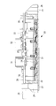
- FIG. 3 is an AA vertical cross-sectional equivalent view of the inverter device shown in FIG. 2. It is a longitudinal cross-sectional equivalent view corresponding to FIG. 3 in the inverter apparatus of the inverter integrated electric compressor which concerns on 2nd Embodiment of this invention.
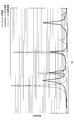
- FIG. 5 is a comparison diagram of vibration modes between the CPU substrate of the inverter device shown in FIG. 3 and FIG. 4 and an inverter device without an elastic resin adhesive layer.
- FIG. 1 shows an external side view of an inverter-integrated electric compressor 1 according to the first embodiment of the present invention.
- the inverter-integrated electric compressor 1 includes a housing 2 constituting an outer shell.
- the housing 2 is configured by integrally fastening and coupling a motor housing 3 in which an electric motor (not shown) is accommodated and a compressor housing 4 in which a compression mechanism (not shown) is accommodated with a bolt 5.
- the motor housing 3 and the compressor housing 4 are pressure vessels and are made of aluminum die casting.
- An electric motor and a compression mechanism (not shown) housed in the housing 2 are connected via a motor shaft, and the compression mechanism is driven by the rotation of the electric motor.
- a refrigerant suction port 6 is provided on one end side (right side in FIG. 1) of the motor housing 3, and low-temperature and low-pressure refrigerant gas sucked into the motor housing 3 from the refrigerant suction port 6 is around the electric motor. After being distributed along the motor axis L direction, it is sucked into the compression mechanism and compressed. The high-temperature and high-pressure refrigerant gas compressed by the compression mechanism is discharged into the compressor housing 4 and then sent out from the discharge port 7 provided on one end side (left side in FIG. 1) of the compressor housing 4. It is configured to be.
- the housing 2 includes, for example, a lower portion on one end side (right side in FIG. 1) of the motor housing 3 and a lower portion on one end side (left side in FIG. 1) of the compressor housing 4 and an upper side 1 of the compressor housing 4.
- Mounting legs 8A, 8B, and 8C are provided at a total of three locations.
- the inverter-integrated electric compressor 1 is mounted on the vehicle side by fixing the mounting legs 8A, 8B, and 8C to the side wall of the driving motor installed in the engine room of the vehicle via brackets and bolts. Installed.
- a box-shaped inverter accommodating portion 9 is integrally formed on the outer periphery of the motor housing 3 at the upper portion thereof.
- the inverter accommodating portion 9 has a box shape surrounded by a peripheral wall having a predetermined height with an open upper surface, and two cable outlets 10 are provided on the side surface.
- the upper surface of the inverter accommodating part 9 is sealed by fixing the lid member 11 with screws.
- FIG. 2 is a perspective view of the inverter device 20
- FIG. 3 is a cross-sectional view corresponding to the AA section in FIG.
- the inverter device 20 is mounted with a plurality of semiconductor switching elements made of an IGBT (not shown), a power metal substrate 21 made of an aluminum plate material on which a snubber capacitor, a discharge resistor, etc. are mounted, and a resin
- the inverter module 23 is integrated with the case 22 by insert molding.
- the resin case 22 includes a power metal substrate 21, a PN terminal 24 connected to a high voltage power source, a UVW terminal 25 for supplying three-phase AC power to the electric motor, a ground 26 and a ground.
- a large number of connection terminals 28 and the like for connecting the terminals 27, the power metal substrate 21 and a CPU substrate 30 described later are integrally formed by insert molding.
- the resin case 22 has a rectangular shape, and a PN terminal 24 protrudes on one side along the side surface of the inverter accommodating portion 9 where the cable outlet 10 is provided.
- a UVW terminal 25 protrudes on one side close to.
- a fixed leg portion 29 that is fastened and fixed to the bottom surface of the inverter accommodating portion 9 via a bolt is integrally formed at the corner portion of the resin case 22.
- the fixed leg 29 is provided with a ground terminal 27 through which a bolt can pass.
- a CPU board (printed board) 30 that is slightly larger than the resin case 22 is disposed in a state where it is connected to a number of connection terminals 28 and the ground 26.
- a control communication circuit having an element that operates at a low voltage, such as a CPU is mounted on the CPU substrate 30, and is configured to control a power system circuit mounted on the power system metal substrate 21.
- the CPU board 30 is provided with a plurality of relatively large and heavy electrical components such as a transformer 31, an electrolytic capacitor 32, and a coil 33 that constitute a control communication circuit.
- thermosetting epoxy resin layer 34 having excellent properties for insulation and moisture resistance is provided.
- This epoxy-based resin layer 34 encloses components mounted on a metal substrate 21 such as an aluminum plate material with a thermosetting resin layer, and not only has insulation and moisture resistance by firmly fixing and protecting, The vibration resistance can also be secured.
- An elastic resin adhesive layer (silicon-based) for bonding to the lower surface of the CPU substrate 30 and absorbing vibration between the upper surface of the epoxy resin layer 34 and the lower surface of the CPU substrate 30 in the resin case 22.
- Resin adhesive layer) 35 is provided.
- the elastic resin adhesive layer 35 is a silicone resin adhesive that maintains a rubber state in a temperature range in which the electric compressor 1 is used, ie, a low temperature range of about ⁇ 40 ° C. to a high temperature range of about several tens of degrees C. (For example, SE9188 equivalent manufactured by Toray Dow Corning Co., Ltd.).
- the glass transition point (Tg) of the silicon-based resin adhesive constituting the elastic resin adhesive layer 35 is set to ⁇ 40 ° C. or lower.
- the elastic resin adhesive layer 35 has a function of absorbing the vibration of the CPU substrate 30, but in order to effectively reduce vibration while suppressing the amount of resin used, the periphery is as shown in FIG.
- Relatively large and heavy electrical equipment such as a central portion of the CPU board 30 supported on the upper surface of the resin case 22 via the connection terminals 28, or a transformer 31, an electrolytic capacitor 32, a coil 33, etc. provided on the CPU board 30. It is provided corresponding to only a specific part such as a lower part of the part.
- the DC power supplied from the high-voltage power supply unit mounted on the vehicle via the high-voltage cable to the inverter device 20 of the electric compressor 1 is input to the power circuit of the power metal substrate 21 via the PN terminal 24, and the CPU
- the electric motor in the motor housing 3 is converted from the UV terminal 25 through the glass sealed terminal after being converted into the three-phase AC power of the control command frequency by the switching operation of the semiconductor switching element controlled by the control circuit of the substrate 30. Is supplied with power.
- the electric motor is rotationally driven at the control command frequency, and the compression mechanism is operated. Due to the operation of the compression mechanism, low-temperature and low-pressure refrigerant gas is sucked into the motor housing 3 from the refrigerant suction port 6.
- the refrigerant flows around the electric motor in the direction of the motor axis L in the direction of the motor axis L toward the compressor housing 4 and is sucked into the compression mechanism. After being compressed into a high-temperature and high-pressure state, the refrigerant passes through the discharge port 7 to the outside of the electric compressor 1. Is sent to.
- the low-temperature and low-pressure refrigerant gas that is sucked into the motor housing 3 from the refrigerant suction port 6 and flows in the direction of the motor axis L is in close contact with the bottom surface of the inverter housing 9 via the housing wall of the motor housing 3.
- the power metal substrate 21 of the inverter device 20 is cooled.
- heat-generating components such as semiconductor switching elements mounted on the power metal substrate 21 are forcibly cooled, so that the heat resistance performance of the inverter device 20 can be ensured.
- the inverter device 20 incorporated in the electric compressor 1 is directly inputted with traveling vibration of the vehicle on which the electric compressor 1 is mounted, vibration of the driving source thereof, vibration of the electric compressor 1 itself, or the like. The For this reason, the vibration is propagated to the power system metal substrate 21 and the CPU substrate 30 constituting the inverter device 20 and also to the electric parts and circuits installed on both the substrates.
- the power system metal substrate 21 is modularized integrally with the resin case 22 and is firmly fixed to the bottom surface of the inverter accommodating portion 9 with bolts via the fixing legs 29 and mounted on the surface thereof.
- the electrical component of the semiconductor switching element is enclosed by a thermosetting epoxy resin layer 34 having a leading edge property and moisture resistance, and is firmly fixed and protected. Therefore, it is possible to sufficiently secure the leading edge property and moisture proof property to the power metal substrate 21 to which a high voltage is applied, and to sufficiently secure the vibration resistance by increasing the rigidity against vibration. Can do.
- the CPU substrate 30 disposed on the upper surface of the inverter module 23 is located between the lower surface and the thermosetting resin layer 34, the central portion of the CPU substrate 30 or the transformer 31 provided on the CPU substrate 30, electrolysis
- the CPU substrate 30 is elastically supported by an elastic resin adhesive layer (silicon-based resin adhesive layer) 35 bonded to a specific portion such as a lower portion of a relatively large and heavy electrical component such as the capacitor 32 and the coil 33. It is made to be able to absorb the excitation force applied to the. As a result, vibration (resonance) of the CPU board 30 can be reduced, and damage or dropout of components on the board due to vibration of the CPU board 30 can be prevented.
- FIG. 5 the one before the countermeasure in which the elastic resin adhesive layer 35 is not provided is a comparative example (vibration mode indicated by a broken line), and the elastic resin adhesive layer 35 is provided corresponding to only the specific portion described above, A vibration mode (indicated by a thick solid line (1)) of the CPU substrate 30 when the CPU substrate 30 is partially bonded is shown.
- Vibration mode indicated by a broken line
- a vibration mode indicated by a thick solid line (1) of the CPU substrate 30 when the CPU substrate 30 is partially bonded is shown.
- the two resin layers 34 and 35 suitable for protecting the power metal substrate 21 and the CPU substrate 30 are provided in the resin case 22 of the inverter module 23, respectively. It is possible to appropriately protect the two substrates 21 and 30 with a small amount of resin, to increase the reliability of the inverter device 20 with respect to vibration resistance, and to reduce the weight of the inverter device 20 and the inverter-integrated electric compressor 1. Can do.
- the elastic resin adhesive layer 35 is applied only to specific parts such as the central part of the CPU board 30 that easily vibrates and the lower parts of heavy components such as the transformer 31, electrolytic capacitor 32, and coil 33 provided on the CPU board 30. Accordingly, the vibration of the CPU board 30 can be effectively suppressed while suppressing the usage amount of the elastic resin adhesive, and the weight and cost of the inverter device 20 can be reduced accordingly. it can.
- a silicon resin adhesive having excellent heat resistance and elasticity in a wide temperature range from a low temperature range to a high temperature range is used, and its glass transition point is set to -40 ° C or lower. Even if it is applied to an in-vehicle inverter-integrated electric compressor 1 that needs to be usable in a wide temperature range from about 100 to several tens of degrees Celsius, the elastic resin adhesive layer 35 maintains the rubber state and the CPU substrate 30 It can be elastically supported. Accordingly, a sufficient vibration absorbing effect can be obtained even in a low temperature environment, and the damage and dropout of components on the board due to the vibration of the CPU board 30 can be reliably prevented, and the vibration resistance of the inverter device 20 can be greatly improved. can do.
- the CPU board 30 since the upper surface of the CPU board 30 is not covered with a resin material or the like, the CPU board 30 can be maintained by removing the lid member 11 of the inverter housing portion 9. Therefore, the maintenance can be facilitated as compared with the case where the upper surface of the CPU substrate 30 is filled with the gel material or the CPU substrate 30 is filled with the resin.
- FIG. 4 differs from the first embodiment described above in that an elastic resin adhesive layer 35A is provided over almost the entire surface between the lower surface of the CPU substrate 30 and the thermosetting resin layer 34. Since other points are the same as those in the first embodiment, description thereof will be omitted.
- the elastic resin adhesive layer 35 ⁇ / b> A is provided over almost the entire surface between the lower surface of the CPU substrate 30 and the thermosetting resin layer 34 provided on the upper surface of the power metal substrate 21. It is set as the structure which provided.
- the elastic resin adhesive layer 35A As described above, by providing the elastic resin adhesive layer 35A over almost the entire surface between the lower surface of the CPU substrate 30 and the thermosetting resin layer 34, the entire lower surface of the CPU substrate 30 is supported by the elastic resin adhesive layer 35A.
- the vibration can be absorbed.
- the lower surface of the CPU substrate 30 is bonded to the entire surface by the elastic resin adhesive layer 35, and as shown in FIG. 5, the vibration is several steps higher than that obtained by partially bonding the CPU substrate 30.
- a reduction effect (vibration mode indicated by a thin solid line (2)) can be obtained. Therefore, according to the present embodiment, although the usage amount of the elastic resin adhesive is somewhat increased, priority can be given to the vibration reduction of the CPU board 30 and the vibration resistance of the inverter device 20 can be further improved.
- the present invention is not limited to the invention according to the above-described embodiment, and can be modified as appropriate without departing from the scope of the invention.
- the inverter housing portion 9 is integrally formed with the motor housing 3 .
- the inverter housing portion 9 is not necessarily formed integrally, and a separate inverter housing portion may be integrally assembled.
- the compression mechanism is not particularly limited, and any type of compression mechanism may be used.
Landscapes
- Engineering & Computer Science (AREA)
- Microelectronics & Electronic Packaging (AREA)
- Mechanical Engineering (AREA)
- General Engineering & Computer Science (AREA)
- Power Engineering (AREA)
- Compressor (AREA)
- Applications Or Details Of Rotary Compressors (AREA)
- Inverter Devices (AREA)
- Physics & Mathematics (AREA)
- Condensed Matter Physics & Semiconductors (AREA)
- General Physics & Mathematics (AREA)
Abstract
耐振性を十分確保できるとともに、軽量化を図ることができるインバータ一体型電動圧縮機およびそのインバータ装置を提供する。インバータ一体型電動圧縮機(1)において、インバータ装置(20)は、半導体スイッチング素子等が実装されているパワー系金属基板(21)と、樹脂製ケース(22)とが一体化されたインバータモジュール(23)を備え、インバータモジュール(23)の上面にCPU等の低電圧で動作する制御通信回路が実装されているCPU基板(30)が設けられた構成とされ、樹脂製ケース(22)内には、パワー系金属基板(21)の上面を覆うように絶縁および防湿用の熱硬化性樹脂層(34)が設けられているとともに、CPU基板(30)の下面と熱硬化性樹脂層(34)との間に、インバータ一体型電動圧縮機(1)の使用温度領域でゴム状態を維持する振動吸収用の弾性樹脂接着材層(35,35A)が設けられている。
Description
本発明は、電動モータと圧縮機構とが内蔵されているハウジングの外周にインバータ装置が一体に組み込まれて構成される車載用空調装置に適用して好適なインバータ一体型電動圧縮機およびそのインバータ装置に関するものである。
車両に搭載される空調装置用圧縮機として、インバータ装置が一体に組み込まれて構成されたインバータ一体型電動圧縮機が種々提案されている。このインバータ一体型電動圧縮機は、一般に電動モータと圧縮機構とが内蔵されているハウジングの外周にインバータ収容部(インバータボックス)が設けられ、その内部に高電圧電源から供給される直流電力を三相交流電力に変換し、ガラス密封端子を介して電動モータに給電するインバータ装置が組み込まれた構成とされている。
インバータ装置は、特許文献1,2に示されるように、直流電力を三相交流電力に変換する複数個の電力用半導体スイッチング素子(IGBT等)が実装されているパワー系基板(台座部、ユニットベースを含む)と、CPU等の低電圧で動作する素子を有する制御通信回路が実装されているCPU基板(プリント基板)とが上下2段に配設され、これがインバータケースあるいは外枠部内に収容されることにより、圧縮機ハウジングの外周部に組み込まれている。
車載用空調装置に適用されるインバータ一体型電動圧縮機は、過酷な温度条件下および振動条件下で使用されることから、インバータ装置においても同様に高い耐振性、防湿性および絶縁性が求められる。このため、特許文献1,2には、インバータ装置が組み込まれるインバータ収容部内にシリコンゲル等のゲル状樹脂材を充填したもの、あるいはゲル状樹脂材中にCPU基板を浮かせて設置したもの等が提案されている。また、特許文献3には、樹脂ケース内に金属基板、制御基板およびインターフェース基板の3層の基板を階層状に配置し、金属基板のパワー半導体面にゲル材を充填するとともに、その表面から制御基板の上面までを樹脂封入したものが提案されている。
しかしながら、特許文献1,2に示されるように、インバータ収容部内にCPU基板の上面を覆う位置までゲル状樹脂材を充填したものにおいては、絶縁性および防湿性を確保することができるとともに、耐振性の向上を図ることができるが、インバータ収容部内全体に充填されるゲル状樹脂材は、重量が重く、かつ高価であることから、インバータ一体型電動圧縮機の重量増大およびコストアップに繋がるという問題があった。特に、車載用空調装置の圧縮機においては、小型軽量化が重要なアイテムであり、従って、如何にして重量増大を回避しながら耐振性を確保して行くかが大きな課題となっている。
また、特許文献3に示されるものでは、樹脂封入される2層目までの基板に対して、絶縁性、防湿性および耐振性を期待することができるが、3層目の基板に対しては、耐振性の確保が困難であるとともに、2層目の制御基板も樹脂材によって封入される構成とされていることから、パワー半導体素子が設置されている金属基板のみならず、制御基板についても実質的にメンテナンスが困難になるという問題があった。
本発明は、このような事情に鑑みてなされたものであって、インバータモジュールの上面に設置されるCPU基板に対しての耐振性を十分確保できるとともに、インバータ装置を軽量化することができるインバータ一体型電動圧縮機およびそのインバータ装置を提供することを目的とする。
上記課題を解決するために、本発明のインバータ一体型電動圧縮機およびそのインバータ装置は、以下の手段を採用する。
すなわち、本発明の一態様にかかるインバータ一体型電動圧縮機は、電動モータおよび圧縮機構が内蔵されているハウジングの外周にインバータ収容部が設けられ、その内部に高電圧電源からの直流電力を三相交流電力に変換して前記電動モータに給電するインバータ装置が設けられているインバータ一体型電動圧縮機において、前記インバータ装置は、半導体スイッチング素子等が実装されているパワー系金属基板と、複数の端子類等が一体にインサート成形された樹脂製ケースとが一体化されたインバータモジュールを備え、該インバータモジュールの上面にCPU等の低電圧で動作する制御通信回路が実装されているCPU基板が設けられた構成とされ、前記樹脂製ケース内には、前記パワー系金属基板の上面を覆うように絶縁および防湿用の熱硬化性樹脂層が設けられているとともに、前記CPU基板の下面と前記熱硬化性樹脂層との間に、前記電動圧縮機の使用温度領域においてゴム状態を維持する振動吸収用の弾性樹脂接着材層が設けられている。
すなわち、本発明の一態様にかかるインバータ一体型電動圧縮機は、電動モータおよび圧縮機構が内蔵されているハウジングの外周にインバータ収容部が設けられ、その内部に高電圧電源からの直流電力を三相交流電力に変換して前記電動モータに給電するインバータ装置が設けられているインバータ一体型電動圧縮機において、前記インバータ装置は、半導体スイッチング素子等が実装されているパワー系金属基板と、複数の端子類等が一体にインサート成形された樹脂製ケースとが一体化されたインバータモジュールを備え、該インバータモジュールの上面にCPU等の低電圧で動作する制御通信回路が実装されているCPU基板が設けられた構成とされ、前記樹脂製ケース内には、前記パワー系金属基板の上面を覆うように絶縁および防湿用の熱硬化性樹脂層が設けられているとともに、前記CPU基板の下面と前記熱硬化性樹脂層との間に、前記電動圧縮機の使用温度領域においてゴム状態を維持する振動吸収用の弾性樹脂接着材層が設けられている。
上記態様によれば、インバータモジュールの樹脂製ケース内に、パワー系金属基板の上面を覆うように絶縁および防湿用の熱硬化性樹脂層が設けられているとともに、インバータモジュールの上面に設けられているCPU基板の下面と熱硬化性樹脂層との間に、電動圧縮機の使用温度領域においてゴム状態を維持する振動吸収用の弾性樹脂接着材層が設けられている。このため、パワー系金属基板に実装されている半導体スイッチング素子等をその上面を覆う熱硬化性樹脂層によってしっかり固めて保護し、高電圧が印加されるパワー系金属基板の前縁性および防湿性を確保することができ、CPU基板に加わる加振力をその下面に設けられている弾性樹脂接着材層によって吸収し、CPU基板が振動することによる基板上の部品の破損や脱落を防止することができる。従って、インバータモジュールの樹脂製ケース内に各々パワー系金属基板およびCPU基板の保護に適した2層の樹脂層を設けることによって、少ない樹脂量で2つの基板を各々適切に保護し、耐振性に対するインバータ装置の信頼性を高めることができるとともに、インバータ一体型電動圧縮機の軽量化を図ることができる。
さらに、本発明の一態様にかかるインバータ一体型電動圧縮機は、上記のインバータ一体型電動圧縮機において、前記弾性樹脂接着材層は、前記CPU基板の中央部位もしくは該CPU基板上に設けられているトランス、電解コンデンサ等の重い部品の下方部位等の特定部位のみに対応して設けられていることとしてもよい。
上記態様によれば、弾性樹脂接着材層が、CPU基板の中央部位もしくはCPU基板上に設けられているトランス、電解コンデンサ等の重い部品の下方部位等の特定部位のみに対応して設けられているため、特に振動し易いCPU基板の中央部位やCPU基板上に設けられているトランス、電解コンデンサ等の重い部品の下方部位等において、弾性樹脂接着材層を介してCPU基板の振動を吸収することができる。従って、弾性樹脂接着材の使用量を抑制しながら効果的にCPU基板の振動を抑制することができ、その分だけインバータ装置の重量低減およびコスト低減を図ることができる。
さらに、本発明の一態様にかかるインバータ一体型電動圧縮機は、上記のインバータ一体型電動圧縮機において、前記弾性樹脂接着材層は、前記CPU基板の下面と前記熱硬化性樹脂層との間のほぼ全面にわたって設けられていることとしてもよい。
上記態様によれば、弾性樹脂接着材層が、CPU基板の下面と熱硬化性樹脂層との間のほぼ全面にわたって設けられているため、CPU基板の下面全体を弾性樹脂接着材層によって支持し、その振動を吸収することができる。この場合、弾性樹脂接着材の使用量は多少多くなるものの、CPU基板の振動低減を優先することができ、インバータ装置の耐振性を一段と向上することができる。
さらに、本発明の一態様にかかるインバータ一体型電動圧縮機は、上述のいずれかのインバータ一体型電動圧縮機において、前記熱硬化性樹脂層は、エポキシ系樹脂により構成されていることとしてもよい。
上記態様によれば、熱硬化性樹脂層が、エポキシ系樹脂により構成されているため、パワー系金属基板上の実装部品を絶縁性および防湿性に優れている熱硬化性エポキシ系樹脂層により覆って(封入して)しっかりと固定し保護することができる。従って、半導体スイッチング素子等が実装されているパワー系金属基板の絶縁性および防湿性並びに耐振性を十分に確保することができる。
さらに、本発明の一態様にかかるインバータ一体型電動圧縮機は、上述のいずれかのインバータ一体型電動圧縮機において、前記弾性樹脂接着材層は、シリコン系樹脂接着材により構成されていることとしてもよい。
上記態様によれば、弾性樹脂接着材層が、シリコン系樹脂接着材により構成されているため、CPU基板の下面を低温域から高温域までの広い温度領域において優れた耐熱性と弾力性を有するシリコン系樹脂接着材層によって弾性支持し、CPU基板に加わる加振力を吸収することができる。従って、CPU基板が振動することによる基板上の部品の破損や脱落を確実に防止し、インバータ装置の耐振性を大幅に向上することができる。
さらに、本発明の一態様にかかるインバータ一体型電動圧縮機は、上記のインバータ一体型電動圧縮機において、前記シリコン系樹脂接着材は、ガラス転移点が-40℃以下に設定されていることとしてもよい。
上記態様によれば、弾性樹脂接着材層を構成するシリコン系樹脂接着材のガラス転移点が-40℃以下に設定されているため、-40℃程度の低温環境下でも使用できるようにする必要がある車載用インバータ一体型電動圧縮機に適用しても、弾性樹脂接着材層はゴム状態を維持しCPU基板を弾性支持することができる。従って、極低温環境下においても十分に振動吸収効果を得ることができる。
さらに、本発明の一態様にかかるインバータ装置は、インバータ一体型電動圧縮機に一体に組み込まれるモジュール化されたインバータ装置であって、前記インバータ装置は、半導体スイッチング素子等が実装されているパワー系金属基板と、複数の端子類等が一体にインサート成形された樹脂製ケースとが一体化されたインバータモジュールを備え、該インバータモジュールの上面にCPU等の低電圧で動作する制御通信回路が実装されているCPU基板が設けられた構成とされ、前記樹脂製ケース内には、パワー系金属基板の上面を覆うように絶縁および防湿用の熱硬化性樹脂層が設けられているとともに、前記CPU基板の下面と前記熱硬化性樹脂層との間に、前記電動圧縮機の使用温度領域においてゴム状態を維持する振動吸収用の弾性樹脂接着材層が設けられていることとしてもよい。
上記態様によれば、インバータモジュールの樹脂製ケース内に、パワー系金属基板の上面を覆うように絶縁および防湿用の熱硬化性樹脂層が設けられているとともに、インバータモジュールの上面に設けられているCPU基板の下面と熱硬化性樹脂層との間に、電動圧縮機の使用温度領域においてゴム状態を維持する振動吸収用の弾性樹脂接着材層が設けられている。このため、パワー系金属基板に実装されている半導体スイッチング素子等をその上面を覆う熱硬化性樹脂層によってしっかり固めて保護し、高電圧が印加されるパワー系金属基板の前縁性および防湿性を確保することができる。また、CPU基板に加わる加振力をその下面に設けられている弾性樹脂接着材層によって吸収し、CPU基板が振動することによる基板上の部品の破損や脱落を防止することができる。従って、インバータモジュールの樹脂製ケース内に各々パワー系金属基板およびCPU基板の保護に適した2層の樹脂層を設けることによって、少ない樹脂量で2つの基板を各々適切に保護し、耐振性に対するインバータ装置の信頼性を高めることができるとともに、インバータ装置の軽量化を図ることができる。
本発明のインバータ一体型電動圧縮機およびそのインバータ装置によると、パワー系金属基板に実装されている半導体スイッチング素子等をその上面を覆う熱硬化性樹脂層によってしっかり固めて保護し、高電圧が印加されるパワー系金属基板の前縁性および防湿性を確保することができる。また、CPU基板に加わる加振力をその下面に設けられている弾性樹脂接着材層によって吸収し、CPU基板が振動することによる基板上の部品の破損や脱落を防止することができる。このため、インバータモジュールの樹脂製ケース内に各々パワー系金属基板およびCPU基板の保護に適した2層の樹脂層を設けることによって、少ない樹脂量で2つの基板を各々適切に保護し、耐振性に対するインバータ装置の信頼性を高めることができるとともに、インバータ装置およびインバータ一体型電動圧縮機の軽量化を図ることができる。
以下に、本発明にかかる実施形態について、図面を参照して説明する。
[第1実施形態]
以下、本発明の第1実施形態について、図1ないし図3および図5を用いて説明する。
図1には、本発明の第1実施形態に係るインバータ一体型電動圧縮機1の外観側面図が示されている。
インバータ一体型電動圧縮機1は、外殻を構成するハウジング2を備えている。このハウジング2は、図示省略の電動モータが収容されているモータハウジング3と、図示省略の圧縮機構が収容されている圧縮機ハウジング4とがボルト5で一体に締め付け結合されることにより構成されている。モータハウジング3および圧縮機ハウジング4は、耐圧容器であり、アルミダイカスト製とされている。
[第1実施形態]
以下、本発明の第1実施形態について、図1ないし図3および図5を用いて説明する。
図1には、本発明の第1実施形態に係るインバータ一体型電動圧縮機1の外観側面図が示されている。
インバータ一体型電動圧縮機1は、外殻を構成するハウジング2を備えている。このハウジング2は、図示省略の電動モータが収容されているモータハウジング3と、図示省略の圧縮機構が収容されている圧縮機ハウジング4とがボルト5で一体に締め付け結合されることにより構成されている。モータハウジング3および圧縮機ハウジング4は、耐圧容器であり、アルミダイカスト製とされている。
ハウジング2の内部に収容されている図示省略の電動モータおよび圧縮機構は、モータ軸を介して連結され、電動モータの回転によって圧縮機構が駆動されるように構成されている。モータハウジング3の一端側(図1の右側)には、冷媒吸入ポート6が設けられており、この冷媒吸入ポート6からモータハウジング3内に吸い込まれた低温低圧の冷媒ガスは、電動モータの周囲をモータ軸線L方向に沿って流通後、圧縮機構に吸い込まれて圧縮される。圧縮機構により圧縮された高温高圧の冷媒ガスは、圧縮機ハウジング4内に吐き出された後、圧縮機ハウジング4の一端側(図1の左側)に設けられている吐出ポート7から外部へと送出されるように構成されている。
ハウジング2には、例えば、モータハウジング3の一端側(図1の右側)の下部および圧縮機ハウジング4の一端側(図1の左側)の下部の2箇所と、圧縮機ハウジング4の上部側1箇所との計3箇所に、取り付け脚8A,8B,8Cが設けられている。インバータ一体型電動圧縮機1は、この取り付け脚8A,8B,8Cが車両のエンジンルーム内に設置されている走行用原動機の側壁等にブラケットおよびボルトを介して固定設置されることにより車両側に搭載される。
モータハウジング3の外周部には、その上部にボックス形状のインバータ収容部9が一体に成形されている。このインバータ収容部9は、上面が開放された所定高さの周囲壁により囲われたボックス形状とされており、側面には、2つのケーブル取り出し口10が設けられている。インバータ収容部9の上面は、蓋部材11がネジ止め固定されることにより密閉されるようになっている。
インバータ収容部9の内部には、車両に搭載されている図示省略の高電圧電源ユニットあるいはバッテリー等から高電圧ケーブルを介して供給される直流電力を三相交流電力に変換し、モータハウジング3の内部に収容されている電動モータに供給するインバータ装置20が収容設置されている。図2には、このインバータ装置20の斜視図が示され、図3には、図2におけるA-A断面相当図が示されている。
インバータ装置20は、図示省略のIGBT等からなる複数個の半導体スイッチング素子が実装されているとともに、スナバコンデンサ、放電抵抗等が実装されているアルミ製板材からなるパワー系金属基板21と、樹脂製ケース22とがインサート成形により一体化されたインバータモジュール23を備えている。樹脂製ケース22には、パワー系金属基板21のほか、高電圧電源と接続されるP-N端子24、電動モータに三相交流電力を給電するU-V-W端子25、アース26およびアース端子27、パワー系金属基板21と後述のCPU基板30との間を接続する多数の接続端子28等が一体にインサート成形されている。
樹脂製ケース22は、矩形形状とされており、インバータ収容部9のケーブル取り出し口10が設けられている側面に沿う一辺にP-N端子24が突出され、これに隣接する圧縮機ハウジング4側に近い一辺にU-V-W端子25が突出されている。また、樹脂製ケース22のコーナー部には、インバータ収容部9の底面にボルトを介して締め付け固定される固定脚部29が一体に成形されている。この固定脚部29にボルトが貫通可能なアース端子27が設けられており、ボルトを介して樹脂製ケース22をインバータ収容部9の底面に固定することによって、パワー系金属基板21および後述のCPU基板30のグランドが筐体接地されるように構成されている。
インバータモジュール23を構成する樹脂製ケース22の上面には、樹脂製ケース22よりもやや大きくされたCPU基板(プリント基板)30が、多数の接続端子28およびアース26と接続された状態で配設されている。CPU基板30には、CPU等の低電圧で動作する素子を有する制御通信回路が実装されており、パワー系金属基板21に実装されているパワー系回路を制御するように構成されている。CPU基板30には、制御通信回路を構成するトランス31、電解コンデンサ32、コイル33等の比較的大きく重い複数の電装部品が設置されている。
さらに、本実施形態においては、上記したインバータ装置20のパワー系金属基板21およびCPU基板30に対する絶縁性、防湿性および耐振性を確保するために、以下のような構成が採用されている。
インバータモジュール23を構成する樹脂製ケース22の内部にあって、IGBT等の複数個の半導体スイッチング素子が実装されているパワー系金属基板21の上面に対してその実装部品の表面を覆うように、絶縁性および防湿性について優れた特性を有する熱硬化性のエポキシ系樹脂層(熱硬化性樹脂層)34が設けられている。このエポキシ系樹脂層34は、アルミ製板材等の金属基板21上に実装されている部品を熱硬化性の樹脂層により封入し、しっかりと固定保護することによって絶縁性および防湿性のみならず、耐振性をも確保できるようにしたものである。
インバータモジュール23を構成する樹脂製ケース22の内部にあって、IGBT等の複数個の半導体スイッチング素子が実装されているパワー系金属基板21の上面に対してその実装部品の表面を覆うように、絶縁性および防湿性について優れた特性を有する熱硬化性のエポキシ系樹脂層(熱硬化性樹脂層)34が設けられている。このエポキシ系樹脂層34は、アルミ製板材等の金属基板21上に実装されている部品を熱硬化性の樹脂層により封入し、しっかりと固定保護することによって絶縁性および防湿性のみならず、耐振性をも確保できるようにしたものである。
樹脂製ケース22内にあって、エポキシ系樹脂層34の上面とCPU基板30の下面との間に、CPU基板30の下面に接着しその振動を吸収するための弾性樹脂接着材層(シリコン系樹脂接着材層)35が設けられている。この弾性樹脂接着材層35は、電動圧縮機1が使用される温度領域である-40℃程度の低温域から百数十℃程度までの高温域で、ゴム状態を維持するシリコン系樹脂接着材(例えば、東レダウコーニング株式会社製SE9188相当品)により構成することができる。弾性樹脂接着材層35を構成するシリコン系樹脂接着材のガラス転移点(Tg)は、-40℃以下に設定される。
弾性樹脂接着材層35は、CPU基板30の振動を吸収する機能を担っているが、使用する樹脂量を抑制しながら効果的に振動を低減するため、図3に示されるように、周辺が樹脂製ケース22の上面に接続端子28を介して支持されているCPU基板30の中央部位、あるいはCPU基板30上に設けられているトランス31、電解コンデンサ32、コイル33等の比較的大きく重い電装部品の下方部位等の特定部位のみに対応して設けられている。
以上に説明の構成により、本実施形態によれば、以下の作用効果を奏する。
車両に搭載の高電圧電源ユニットから高電圧ケーブルを経て電動圧縮機1のインバータ装置20に供給された直流電力は、P-N端子24を経てパワー系金属基板21のパワー回路に入力され、CPU基板30の制御回路により制御される半導体スイッチング素子のスイッチング動作により制御指令周波数の三相交流電力に変換された後、U-V-W端子25からガラス密封端子を経てモータハウジング3内の電動モータに給電される。
車両に搭載の高電圧電源ユニットから高電圧ケーブルを経て電動圧縮機1のインバータ装置20に供給された直流電力は、P-N端子24を経てパワー系金属基板21のパワー回路に入力され、CPU基板30の制御回路により制御される半導体スイッチング素子のスイッチング動作により制御指令周波数の三相交流電力に変換された後、U-V-W端子25からガラス密封端子を経てモータハウジング3内の電動モータに給電される。
これにより、電動モータが制御指令周波数で回転駆動され、圧縮機構が動作される。圧縮機構の動作により、冷媒吸入ポート6から低温低圧の冷媒ガスがモータハウジング3内に吸い込まれる。この冷媒は、電動モータの周囲をモータ軸線L方向に圧縮機ハウジング4側へと流動されて圧縮機構に吸い込まれ、高温高圧状態に圧縮された後、吐出ポート7を経て電動圧縮機1の外部へと送出される。
この間、冷媒吸入ポート6からモータハウジング3内に吸い込まれ、モータ軸線L方向に流動される低温低圧の冷媒ガスは、モータハウジング3のハウジング壁を介してインバータ収納部9の底面に密着されて設置されているインバータ装置20のパワー系金属基板21を冷却する。これによって、パワー系金属基板21に実装されている半導体スイッチング素子等の発熱部品が強制冷却されるため、インバータ装置20の耐熱性能を確保することができる。
一方、電動圧縮機1に組み込まれているインバータ装置20には、電動圧縮機1が搭載されている車両の走行振動やその駆動源の振動、あるいは電動圧縮機1自体の振動等が直接入力される。このため、インバータ装置20を構成しているパワー系金属基板21やCPU基板30、さらには両基板上に設置されている電装部品や回路に対してもその振動が伝播される。
しかるに、パワー系金属基板21は、樹脂製ケース22と一体にモジュール化され、インバータ収容部9の底面に固定脚部29を介してボルトで強固に締め付け固定されるとともに、その表面に実装されている半導体スイッチング素子の電装部品は、前縁性および防湿性を有する熱硬化性のエポキシ系樹脂層34によって封入され、しっかりと固定保護されている。従って、高電圧が印加されるパワー系金属基板21に対して前縁性および防湿性を十分確保することができるとともに、振動に対してもその剛性を高めることによって耐振性を十分に確保することができる。
インバータモジュール23の上面に配設されているCPU基板30は、その下面と熱硬化性樹脂層34との間において、CPU基板30の中央部位もしくはCPU基板30上に設けられているトランス31、電解コンデンサ32、コイル33等の比較的大きく重い電装部品の下方部位等の特定部位に対応して接着されている弾性樹脂接着材層(シリコン系樹脂接着材層)35により弾性支持され、CPU基板30に加わる加振力を吸収できるようにされている。これによって、CPU基板30の振動(共振)を低減することができ、CPU基板30が振動することによる基板上の部品の破損や脱落を防止することができる。
図5には、弾性樹脂接着材層35が設けられていない対策前のものを比較例(破線で示す振動モード)とし、上記した特定部位のみに対応して弾性樹脂接着材層35を設け、CPU基板30を部分接着した場合におけるCPU基板30の振動モード(太い実線(1)で示す)が示されている。同図からも明らかなように、CPU基板30の下面の特定部位に対応して弾性樹脂接着材層35を設け、CPU基板30を部分接着した構成とすることによって、広い周波数範囲においてCPU基板30の振動を低減することができる。
このように、本実施形態によれば、インバータモジュール23の樹脂製ケース22内に各々パワー系金属基板21およびCPU基板30の保護に適した2層の樹脂層34,35を設けているため、少ない樹脂量で2つの基板21,30を各々適切に保護し、耐振性に対するインバータ装置20の信頼性を高めることができるとともに、インバータ装置20およびインバータ一体型電動圧縮機1の軽量化を図ることができる。
特に、弾性樹脂接着材層35を振動し易いCPU基板30の中央部位やCPU基板30上に設けられているトランス31、電解コンデンサ32、コイル33等の重い部品の下方部位等の特定部位のみに対応して設けているため、弾性樹脂接着材の使用量を抑制しながら効果的にCPU基板30の振動を抑制することができ、その分だけインバータ装置20の重量低減およびコスト低減を図ることができる。
また、低温域から高温域までの広い温度領域で優れた耐熱性と弾力性を有するシリコン系樹脂接着材を用い、そのガラス転移点が-40℃以下に設定されているため、-40℃程度から百数十℃程度の広い温度領域において使用可能とする必要がある車載用のインバータ一体型電動圧縮機1に適用しても、弾性樹脂接着材層35はゴム状態を維持しCPU基板30を弾性支持することができる。従って、低温環境下においても十分に振動吸収効果を得ることができ、CPU基板30が振動することによる基板上の部品の破損や脱落を確実に防止し、インバータ装置20の耐振性を大幅に向上することができる。
さらに、CPU基板30の上面が樹脂材等によって覆われていないため、インバータ収容部9の蓋部材11を取り外すことによって、CPU基板30に対するメンテナンスが可能となる。従って、CPU基板30の上面までゲル材を充填したものやCPU基板30を樹脂封入したものに比べ、メンテナンスの容易化を図ることができる。
[第2実施形態]
次に、本発明の第2実施形態について、図4を用いて説明する。
本実施形態は、上記した第1実施形態に対して、弾性樹脂接着材層35AをCPU基板30の下面と熱硬化性樹脂層34との間のほぼ全面にわたり設けている点が異なる。その他の点については、第1実施形態と同様であるので説明は省略する。
本実施形態では、図4に示されるように、CPU基板30の下面とパワー系金属基板21の上面に設けられている熱硬化性樹脂層34との間のほぼ全面にわたって弾性樹脂接着材層35Aを設けた構成としている。
次に、本発明の第2実施形態について、図4を用いて説明する。
本実施形態は、上記した第1実施形態に対して、弾性樹脂接着材層35AをCPU基板30の下面と熱硬化性樹脂層34との間のほぼ全面にわたり設けている点が異なる。その他の点については、第1実施形態と同様であるので説明は省略する。
本実施形態では、図4に示されるように、CPU基板30の下面とパワー系金属基板21の上面に設けられている熱硬化性樹脂層34との間のほぼ全面にわたって弾性樹脂接着材層35Aを設けた構成としている。
上記のように、CPU基板30の下面と熱硬化性樹脂層34との間のほぼ全面にわたって弾性樹脂接着材層35Aを設けることにより、CPU基板30の下面全体を弾性樹脂接着材層35Aによって支持し、その振動を吸収することができる。この構成の場合、CPU基板30の下面が弾性樹脂接着材層35により全面接着されることになり、図5に示されるように、CPU基板30を部分接着したものに比べても数段高い振動低減効果(細い実線(2)で示す振動モード)を得ることができる。従って、本実施形態によれば、弾性樹脂接着材の使用量は多少多くなるものの、CPU基板30の振動低減を優先することができ、インバータ装置20の耐振性を更に向上することができる。
本発明は、上記実施形態にかかる発明に限定されるものではなく、その要旨を逸脱しない範囲において、適宜変形が可能である。例えば、上記実施形態では、インバータ収容部9をモータハウジング3と一体成形した例について説明したが、必ずしも一体に成形する必要はなく、別体をなすインバータ収容部を一体に組み付けた構成としてもよい。圧縮機構については、特に制限されるものではなく、如何なる形式の圧縮機構を用いてもよい。
1 インバータ一体型電動圧縮機
2 ハウジング
9 インバータ収容部
20 インバータ装置
21 パワー系金属基板
22 樹脂製ケース
23 インバータモジュール
24 P-N端子
25 U-V-W端子
28 接続端子
30 CPU基板
31 トランス
32 電解コンデンサ
33 コイル
34 エポキシ系樹脂層(熱硬化性樹脂層)
35,35A 弾性樹脂接着材層(シリコン系樹脂接着材層)
2 ハウジング
9 インバータ収容部
20 インバータ装置
21 パワー系金属基板
22 樹脂製ケース
23 インバータモジュール
24 P-N端子
25 U-V-W端子
28 接続端子
30 CPU基板
31 トランス
32 電解コンデンサ
33 コイル
34 エポキシ系樹脂層(熱硬化性樹脂層)
35,35A 弾性樹脂接着材層(シリコン系樹脂接着材層)
Claims (7)
- 電動モータおよび圧縮機構が内蔵されているハウジングの外周にインバータ収容部が設けられ、その内部に高電圧電源からの直流電力を三相交流電力に変換して前記電動モータに給電するインバータ装置が設けられているインバータ一体型電動圧縮機において、
前記インバータ装置は、半導体スイッチング素子等が実装されているパワー系金属基板と、複数の端子類等が一体にインサート成形された樹脂製ケースとが一体化されたインバータモジュールを備え、該インバータモジュールの上面にCPU等の低電圧で動作する制御通信回路が実装されているCPU基板が設けられた構成とされ、
前記樹脂製ケース内には、前記パワー系金属基板の上面を覆うように絶縁および防湿用の熱硬化性樹脂層が設けられているとともに、前記CPU基板の下面と前記熱硬化性樹脂層との間に、前記電動圧縮機の使用温度領域においてゴム状態を維持する振動吸収用の弾性樹脂接着材層が設けられているインバータ一体型電動圧縮機。 - 前記弾性樹脂接着材層は、前記CPU基板の中央部位もしくは該CPU基板上に設けられているトランス、電解コンデンサ等の重い部品の下方部位等の特定部位のみに対応して設けられている請求項1に記載のインバータ一体型電動圧縮機。
- 前記弾性樹脂接着材層は、前記CPU基板の下面と前記熱硬化性樹脂層との間のほぼ全面にわたって設けられている請求項1に記載のインバータ一体型電動圧縮機。
- 前記熱硬化性樹脂層は、エポキシ系樹脂により構成されている請求項1ないし3のいずれかに記載のインバータ一体型電動圧縮機。
- 前記弾性樹脂接着材層は、シリコン系樹脂接着材により構成されている請求項1ないし4のいずれかに記載のインバータ一体型電動圧縮機。
- 前記シリコン系樹脂接着材は、ガラス転移点が-40℃以下に設定されている請求項5に記載のインバータ一体型電動圧縮機。
- インバータ一体型電動圧縮機に一体に組み込まれるモジュール化されたインバータ装置であって、
前記インバータ装置は、半導体スイッチング素子等が実装されているパワー系金属基板と、複数の端子類等が一体にインサート成形された樹脂製ケースとが一体化されたインバータモジュールを備え、該インバータモジュールの上面にCPU等の低電圧で動作する制御通信回路が実装されているCPU基板が設けられた構成とされ、
前記樹脂製ケース内には、パワー系金属基板の上面を覆うように絶縁および防湿用の熱硬化性樹脂層が設けられているとともに、前記CPU基板の下面と前記熱硬化性樹脂層との間に、前記電動圧縮機の使用温度領域においてゴム状態を維持する振動吸収用の弾性樹脂接着材層が設けられているインバータ装置。
Priority Applications (2)
| Application Number | Priority Date | Filing Date | Title |
|---|---|---|---|
| US13/000,775 US8717765B2 (en) | 2008-12-05 | 2009-11-26 | Integrated-inverter electric compressor and inverter unit thereof |
| EP09830332.4A EP2357361B1 (en) | 2008-12-05 | 2009-11-26 | Integrated-inverter electric compressor and inverter unit thereof |
Applications Claiming Priority (2)
| Application Number | Priority Date | Filing Date | Title |
|---|---|---|---|
| JP2008-311305 | 2008-12-05 | ||
| JP2008311305A JP5412098B2 (ja) | 2008-12-05 | 2008-12-05 | インバータ一体型電動圧縮機およびそのインバータ装置 |
Publications (1)
| Publication Number | Publication Date |
|---|---|
| WO2010064565A1 true WO2010064565A1 (ja) | 2010-06-10 |
Family
ID=42233216
Family Applications (1)
| Application Number | Title | Priority Date | Filing Date |
|---|---|---|---|
| PCT/JP2009/069918 Ceased WO2010064565A1 (ja) | 2008-12-05 | 2009-11-26 | インバータ一体型電動圧縮機およびそのインバータ装置 |
Country Status (4)
| Country | Link |
|---|---|
| US (1) | US8717765B2 (ja) |
| EP (1) | EP2357361B1 (ja) |
| JP (1) | JP5412098B2 (ja) |
| WO (1) | WO2010064565A1 (ja) |
Cited By (1)
| Publication number | Priority date | Publication date | Assignee | Title |
|---|---|---|---|---|
| DE102013015189A1 (de) | 2013-09-11 | 2015-03-12 | Fraunhofer-Gesellschaft zur Förderung der angewandten Forschung e.V. | Mobiles Kamerasystem mit einer eigenfortbewegungsfähigen Plattform sowie Verfahren zur optischen Erfassung wenigstens eines Objektes |
Families Citing this family (20)
| Publication number | Priority date | Publication date | Assignee | Title |
|---|---|---|---|---|
| JP5626200B2 (ja) * | 2011-01-06 | 2014-11-19 | 株式会社豊田自動織機 | 電気部品の固定構造 |
| US8674568B2 (en) * | 2011-01-21 | 2014-03-18 | Remy Technologies, L.L.C. | Machine with high voltage enclosure cover |
| FR2977120B1 (fr) * | 2011-06-24 | 2013-06-07 | Valeo Japan Co Ltd | Carte de circuit imprime pour boitier de compresseur |
| US8957752B2 (en) | 2011-10-07 | 2015-02-17 | Sabic Global Technologies B.V. | Inverter housing system |
| JP6173763B2 (ja) | 2013-04-26 | 2017-08-02 | 三菱重工オートモーティブサーマルシステムズ株式会社 | インバータ一体型電動圧縮機 |
| JP5951553B2 (ja) * | 2013-04-26 | 2016-07-13 | 三菱重工オートモーティブサーマルシステムズ株式会社 | インバータ一体型電動圧縮機 |
| GB2509799B (en) * | 2013-06-26 | 2015-10-07 | Protean Electric Ltd | An electric motor or generator |
| KR101337542B1 (ko) * | 2013-09-13 | 2013-12-06 | 국방과학연구소 | 전기차량의 전기추진시스템 |
| DE102013222905A1 (de) * | 2013-11-11 | 2015-05-13 | Oerlikon Leybold Vacuum Gmbh | Antriebs- und Steuereinrichtung für eine Vakuumpumpe, Vakuumpumpe sowie Verfahren zum Herstellen einer Steuerplatine für eine Vakuumpumpe |
| DE102014207023B3 (de) * | 2014-04-11 | 2015-07-30 | Magna Powertrain Hückeswagen GmbH | Kraftfahrzeug-Vakuumpumpe mit Verklebung |
| CN105099084B (zh) * | 2014-05-15 | 2017-10-17 | 中山大洋电机股份有限公司 | 将牵引电机和逆变器集成的一体化动力系统 |
| JP6682824B2 (ja) * | 2015-11-25 | 2020-04-15 | 富士電機株式会社 | 半導体装置 |
| CN107482878A (zh) * | 2017-08-17 | 2017-12-15 | 重庆路格科技有限公司 | 除露降温开关电源 |
| DE102018200195B4 (de) * | 2018-01-09 | 2025-07-31 | Bühler Motor GmbH | Antrieb mit einem kommutatormotor |
| USD954668S1 (en) * | 2019-01-10 | 2022-06-14 | Wolfspeed, Inc. | Housing for a power module assembly |
| JP7135967B2 (ja) * | 2019-03-27 | 2022-09-13 | 株式会社豊田自動織機 | 電動圧縮機 |
| CN110417281A (zh) * | 2019-07-05 | 2019-11-05 | 深圳市钰龙科技有限公司 | 一种正弦波逆变器充电电源 |
| US11353022B2 (en) | 2020-05-28 | 2022-06-07 | Emerson Climate Technologies, Inc. | Compressor having damped scroll |
| CN115638104A (zh) * | 2021-07-19 | 2023-01-24 | 杭州奥科美瑞科技有限公司 | 流体驱动装置 |
| DE202022104286U1 (de) * | 2022-07-28 | 2023-11-07 | Reinz-Dichtungs-Gmbh | Abdeckung für eine Komponente eines elektrischen Antriebssystems und damit versehene Komponente |
Citations (7)
| Publication number | Priority date | Publication date | Assignee | Title |
|---|---|---|---|---|
| JPH06291235A (ja) * | 1993-03-31 | 1994-10-18 | Sanyo Electric Co Ltd | 混成集積回路 |
| JPH10270609A (ja) * | 1997-03-28 | 1998-10-09 | Mitsubishi Electric Corp | パワー半導体装置及びその製造方法 |
| JP2000150724A (ja) * | 1998-11-13 | 2000-05-30 | Toshiba Corp | 半導体装置 |
| JP2003153552A (ja) * | 2001-11-07 | 2003-05-23 | Matsushita Electric Ind Co Ltd | インバータ回路の配設構造と配設方法及び圧縮機 |
| JP2004053050A (ja) | 2002-07-17 | 2004-02-19 | Hitachi Ltd | 冷凍装置及びそれに用いられるインバータ装置 |
| JP2006316754A (ja) | 2005-05-16 | 2006-11-24 | Mitsubishi Heavy Ind Ltd | 車両用電動圧縮機 |
| JP2007315269A (ja) | 2006-05-25 | 2007-12-06 | Mitsubishi Heavy Ind Ltd | インバータ一体型電動圧縮機 |
Family Cites Families (9)
| Publication number | Priority date | Publication date | Assignee | Title |
|---|---|---|---|---|
| US5559374A (en) * | 1993-03-25 | 1996-09-24 | Sanyo Electric Co., Ltd. | Hybrid integrated circuit |
| JPH1113635A (ja) * | 1997-06-30 | 1999-01-19 | Matsushita Electric Ind Co Ltd | 圧縮機駆動装置 |
| US6303860B1 (en) * | 1999-11-30 | 2001-10-16 | Bombardier Motor Corporation Of America | Bladder insert for encapsulant displacement |
| JP2002070743A (ja) * | 2000-08-29 | 2002-03-08 | Sanden Corp | 冷媒圧縮用電動式圧縮機 |
| JP4691819B2 (ja) * | 2001-04-25 | 2011-06-01 | 株式会社安川電機 | インバータ装置 |
| JP3526291B2 (ja) * | 2001-04-25 | 2004-05-10 | 三菱電機株式会社 | コンデンサモジュールおよびそれを用いた半導体装置 |
| US8007255B2 (en) * | 2006-11-22 | 2011-08-30 | Mitsubishi Heavy Industries, Ltd. | Inverter-integrated electric compressor with inverter storage box arrangement |
| JP5247045B2 (ja) * | 2007-02-22 | 2013-07-24 | サンデン株式会社 | インバータ一体型電動圧縮機の製造方法 |
| JP5010516B2 (ja) * | 2008-03-26 | 2012-08-29 | 三菱重工業株式会社 | インバータ一体型電動圧縮機およびそのインバータ装置 |
-
2008
- 2008-12-05 JP JP2008311305A patent/JP5412098B2/ja active Active
-
2009
- 2009-11-26 EP EP09830332.4A patent/EP2357361B1/en active Active
- 2009-11-26 WO PCT/JP2009/069918 patent/WO2010064565A1/ja not_active Ceased
- 2009-11-26 US US13/000,775 patent/US8717765B2/en active Active
Patent Citations (7)
| Publication number | Priority date | Publication date | Assignee | Title |
|---|---|---|---|---|
| JPH06291235A (ja) * | 1993-03-31 | 1994-10-18 | Sanyo Electric Co Ltd | 混成集積回路 |
| JPH10270609A (ja) * | 1997-03-28 | 1998-10-09 | Mitsubishi Electric Corp | パワー半導体装置及びその製造方法 |
| JP2000150724A (ja) * | 1998-11-13 | 2000-05-30 | Toshiba Corp | 半導体装置 |
| JP2003153552A (ja) * | 2001-11-07 | 2003-05-23 | Matsushita Electric Ind Co Ltd | インバータ回路の配設構造と配設方法及び圧縮機 |
| JP2004053050A (ja) | 2002-07-17 | 2004-02-19 | Hitachi Ltd | 冷凍装置及びそれに用いられるインバータ装置 |
| JP2006316754A (ja) | 2005-05-16 | 2006-11-24 | Mitsubishi Heavy Ind Ltd | 車両用電動圧縮機 |
| JP2007315269A (ja) | 2006-05-25 | 2007-12-06 | Mitsubishi Heavy Ind Ltd | インバータ一体型電動圧縮機 |
Non-Patent Citations (1)
| Title |
|---|
| See also references of EP2357361A4 |
Cited By (1)
| Publication number | Priority date | Publication date | Assignee | Title |
|---|---|---|---|---|
| DE102013015189A1 (de) | 2013-09-11 | 2015-03-12 | Fraunhofer-Gesellschaft zur Förderung der angewandten Forschung e.V. | Mobiles Kamerasystem mit einer eigenfortbewegungsfähigen Plattform sowie Verfahren zur optischen Erfassung wenigstens eines Objektes |
Also Published As
| Publication number | Publication date |
|---|---|
| EP2357361A4 (en) | 2017-05-17 |
| JP2010133366A (ja) | 2010-06-17 |
| EP2357361B1 (en) | 2019-05-22 |
| EP2357361A1 (en) | 2011-08-17 |
| JP5412098B2 (ja) | 2014-02-12 |
| US20110095659A1 (en) | 2011-04-28 |
| US8717765B2 (en) | 2014-05-06 |
Similar Documents
| Publication | Publication Date | Title |
|---|---|---|
| JP5412098B2 (ja) | インバータ一体型電動圧縮機およびそのインバータ装置 | |
| JP5839769B2 (ja) | インバータモジュールおよびインバータ一体型電動圧縮機 | |
| JP5107114B2 (ja) | インバータ一体型電動圧縮機 | |
| JP5107133B2 (ja) | インバータ一体型電動圧縮機 | |
| CN103222176B (zh) | 逆变器模块和逆变器一体型电动压缩机 | |
| US10122247B2 (en) | Inverter-integrated electric compressor | |
| JP5308008B2 (ja) | 車載空調装置用電動圧縮機 | |
| JP5861614B2 (ja) | 高電圧電気装置及び電動圧縮機 | |
| JP5010516B2 (ja) | インバータ一体型電動圧縮機およびそのインバータ装置 | |
| CN105190033B (zh) | 逆变器一体式电动压缩机 | |
| JP2009127523A (ja) | インバータ一体型電動圧縮機 | |
| EP2197097B1 (en) | Inverter-integrated electric compressor and coil component for inverter thereof | |
| JP2012117444A (ja) | インバータ収納部およびこれを備えているインバータ一体型電動圧縮機 | |
| JP2012117445A (ja) | インバータ収納部およびこれを備えているインバータ一体型電動圧縮機 | |
| JP5595461B2 (ja) | インバータ一体型電動圧縮機 | |
| JP5574794B2 (ja) | インバータ一体型電動圧縮機 |
Legal Events
| Date | Code | Title | Description |
|---|---|---|---|
| 121 | Ep: the epo has been informed by wipo that ep was designated in this application |
Ref document number: 09830332 Country of ref document: EP Kind code of ref document: A1 |
|
| WWE | Wipo information: entry into national phase |
Ref document number: 13000775 Country of ref document: US Ref document number: 2009830332 Country of ref document: EP |
|
| NENP | Non-entry into the national phase |
Ref country code: DE |