WO2010067724A1 - 電池装置 - Google Patents
電池装置 Download PDFInfo
- Publication number
- WO2010067724A1 WO2010067724A1 PCT/JP2009/070111 JP2009070111W WO2010067724A1 WO 2010067724 A1 WO2010067724 A1 WO 2010067724A1 JP 2009070111 W JP2009070111 W JP 2009070111W WO 2010067724 A1 WO2010067724 A1 WO 2010067724A1
- Authority
- WO
- WIPO (PCT)
- Prior art keywords
- battery
- management means
- battery management
- identification information
- management unit
- Prior art date
- Legal status (The legal status is an assumption and is not a legal conclusion. Google has not performed a legal analysis and makes no representation as to the accuracy of the status listed.)
- Ceased
Links
Images

Classifications
-
- H—ELECTRICITY
- H01—ELECTRIC ELEMENTS
- H01M—PROCESSES OR MEANS, e.g. BATTERIES, FOR THE DIRECT CONVERSION OF CHEMICAL ENERGY INTO ELECTRICAL ENERGY
- H01M10/00—Secondary cells; Manufacture thereof
- H01M10/42—Methods or arrangements for servicing or maintenance of secondary cells or secondary half-cells
- H01M10/425—Structural combination with electronic components, e.g. electronic circuits integrated to the outside of the casing
- H01M10/4257—Smart batteries, e.g. electronic circuits inside the housing of the cells or batteries
-
- H—ELECTRICITY
- H01—ELECTRIC ELEMENTS
- H01M—PROCESSES OR MEANS, e.g. BATTERIES, FOR THE DIRECT CONVERSION OF CHEMICAL ENERGY INTO ELECTRICAL ENERGY
- H01M10/00—Secondary cells; Manufacture thereof
- H01M10/42—Methods or arrangements for servicing or maintenance of secondary cells or secondary half-cells
- H01M10/425—Structural combination with electronic components, e.g. electronic circuits integrated to the outside of the casing
-
- H—ELECTRICITY
- H01—ELECTRIC ELEMENTS
- H01M—PROCESSES OR MEANS, e.g. BATTERIES, FOR THE DIRECT CONVERSION OF CHEMICAL ENERGY INTO ELECTRICAL ENERGY
- H01M10/00—Secondary cells; Manufacture thereof
- H01M10/42—Methods or arrangements for servicing or maintenance of secondary cells or secondary half-cells
- H01M10/48—Accumulators combined with arrangements for measuring, testing or indicating the condition of cells, e.g. the level or density of the electrolyte
- H01M10/482—Accumulators combined with arrangements for measuring, testing or indicating the condition of cells, e.g. the level or density of the electrolyte for several batteries or cells simultaneously or sequentially
-
- H—ELECTRICITY
- H01—ELECTRIC ELEMENTS
- H01M—PROCESSES OR MEANS, e.g. BATTERIES, FOR THE DIRECT CONVERSION OF CHEMICAL ENERGY INTO ELECTRICAL ENERGY
- H01M10/00—Secondary cells; Manufacture thereof
- H01M10/42—Methods or arrangements for servicing or maintenance of secondary cells or secondary half-cells
- H01M10/48—Accumulators combined with arrangements for measuring, testing or indicating the condition of cells, e.g. the level or density of the electrolyte
- H01M10/486—Accumulators combined with arrangements for measuring, testing or indicating the condition of cells, e.g. the level or density of the electrolyte for measuring temperature
-
- H—ELECTRICITY
- H02—GENERATION; CONVERSION OR DISTRIBUTION OF ELECTRIC POWER
- H02J—ELECTRIC POWER NETWORKS; CIRCUIT ARRANGEMENTS OR SYSTEMS FOR SUPPLYING OR DISTRIBUTING ELECTRIC POWER; SYSTEMS FOR STORING ELECTRIC ENERGY
- H02J7/00—Circuit arrangements for charging or discharging batteries or for supplying loads from batteries
- H02J7/40—Circuit arrangements for charging or discharging batteries or for supplying loads from batteries characterised by the exchange of charge or discharge related data
- H02J7/42—Circuit arrangements for charging or discharging batteries or for supplying loads from batteries characterised by the exchange of charge or discharge related data with electronic devices having internal batteries, e.g. mobile phones
-
- H—ELECTRICITY
- H02—GENERATION; CONVERSION OR DISTRIBUTION OF ELECTRIC POWER
- H02J—ELECTRIC POWER NETWORKS; CIRCUIT ARRANGEMENTS OR SYSTEMS FOR SUPPLYING OR DISTRIBUTING ELECTRIC POWER; SYSTEMS FOR STORING ELECTRIC ENERGY
- H02J7/00—Circuit arrangements for charging or discharging batteries or for supplying loads from batteries
- H02J7/40—Circuit arrangements for charging or discharging batteries or for supplying loads from batteries characterised by the exchange of charge or discharge related data
- H02J7/443—Circuit arrangements for charging or discharging batteries or for supplying loads from batteries characterised by the exchange of charge or discharge related data using passive battery identification means, e.g. resistors or capacitors
-
- H—ELECTRICITY
- H02—GENERATION; CONVERSION OR DISTRIBUTION OF ELECTRIC POWER
- H02J—ELECTRIC POWER NETWORKS; CIRCUIT ARRANGEMENTS OR SYSTEMS FOR SUPPLYING OR DISTRIBUTING ELECTRIC POWER; SYSTEMS FOR STORING ELECTRIC ENERGY
- H02J7/00—Circuit arrangements for charging or discharging batteries or for supplying loads from batteries
- H02J7/50—Circuit arrangements for charging or discharging batteries or for supplying loads from batteries acting upon multiple batteries simultaneously or sequentially
-
- G—PHYSICS
- G01—MEASURING; TESTING
- G01R—MEASURING ELECTRIC VARIABLES; MEASURING MAGNETIC VARIABLES
- G01R31/00—Arrangements for testing electric properties; Arrangements for locating electric faults; Arrangements for electrical testing characterised by what is being tested not provided for elsewhere
- G01R31/36—Arrangements for testing, measuring or monitoring the electrical condition of accumulators or electric batteries, e.g. capacity or state of charge [SoC]
- G01R31/396—Acquisition or processing of data for testing or for monitoring individual cells or groups of cells within a battery
-
- H—ELECTRICITY
- H01—ELECTRIC ELEMENTS
- H01M—PROCESSES OR MEANS, e.g. BATTERIES, FOR THE DIRECT CONVERSION OF CHEMICAL ENERGY INTO ELECTRICAL ENERGY
- H01M10/00—Secondary cells; Manufacture thereof
- H01M10/05—Accumulators with non-aqueous electrolyte
- H01M10/052—Li-accumulators
- H01M10/0525—Rocking-chair batteries, i.e. batteries with lithium insertion or intercalation in both electrodes; Lithium-ion batteries
-
- H—ELECTRICITY
- H01—ELECTRIC ELEMENTS
- H01M—PROCESSES OR MEANS, e.g. BATTERIES, FOR THE DIRECT CONVERSION OF CHEMICAL ENERGY INTO ELECTRICAL ENERGY
- H01M10/00—Secondary cells; Manufacture thereof
- H01M10/06—Lead-acid accumulators
-
- H—ELECTRICITY
- H01—ELECTRIC ELEMENTS
- H01M—PROCESSES OR MEANS, e.g. BATTERIES, FOR THE DIRECT CONVERSION OF CHEMICAL ENERGY INTO ELECTRICAL ENERGY
- H01M10/00—Secondary cells; Manufacture thereof
- H01M10/42—Methods or arrangements for servicing or maintenance of secondary cells or secondary half-cells
- H01M10/425—Structural combination with electronic components, e.g. electronic circuits integrated to the outside of the casing
- H01M2010/4278—Systems for data transfer from batteries, e.g. transfer of battery parameters to a controller, data transferred between battery controller and main controller
-
- Y—GENERAL TAGGING OF NEW TECHNOLOGICAL DEVELOPMENTS; GENERAL TAGGING OF CROSS-SECTIONAL TECHNOLOGIES SPANNING OVER SEVERAL SECTIONS OF THE IPC; TECHNICAL SUBJECTS COVERED BY FORMER USPC CROSS-REFERENCE ART COLLECTIONS [XRACs] AND DIGESTS
- Y02—TECHNOLOGIES OR APPLICATIONS FOR MITIGATION OR ADAPTATION AGAINST CLIMATE CHANGE
- Y02E—REDUCTION OF GREENHOUSE GAS [GHG] EMISSIONS, RELATED TO ENERGY GENERATION, TRANSMISSION OR DISTRIBUTION
- Y02E60/00—Enabling technologies; Technologies with a potential or indirect contribution to GHG emissions mitigation
- Y02E60/10—Energy storage using batteries
Definitions
- the present invention relates to a battery device.
- Patent Document 1 Japanese Patent Application Laid-Open No. 2004-193643
- a newly connected terminal transmits a connection request message including temporary identification information to another terminal, and as a response, the terminal competes with temporary identification information from the other terminal that has received the connection request message.
- a technique for setting temporary identification information as its own identification information when a contention message indicating a terminal having identification information is not received is disclosed. Further, for example, in Japanese Patent No.
- the central apparatus periodically transmits an identification information allocation request message to a plurality of terminals connected via a network, and transmits the identification information to the network.
- An identification information allocation request message to a plurality of terminals connected via a network, and transmits the identification information to the network.
- Patent Document 1 since a newly connected terminal uses temporary identification information to generate a request message, there is a problem that the ascending / descending order of identification information cannot be managed.
- the invention disclosed in Patent Document 2 has a problem in that an allocation request message is periodically transmitted, resulting in a communication load.
- the present invention has been made in order to solve the above-described problem, and provides a battery device capable of avoiding an increase in communication load and assigning identification information that matches the physical connection order of each column battery.
- the purpose is to provide.
- the present invention employs the following means.
- the present invention provides a column battery group in which a plurality of column batteries each having one or more battery cells are connected in series, and is provided corresponding to each of the column batteries, and manages the battery state of the corresponding column battery.
- a second communication line for connecting the battery management means in a daisy chain, and a first communication for connecting any one of the battery management means at the end of the plurality of battery management means and the central management means.
- Each of the battery management means stores the determined identification information when the identification information is determined in communication with the central management means, and is located downstream of itself.
- a battery device in which the connection switching unit with another battery management unit is set in a connected state so that the other battery management unit and the central management unit can communicate with each other.
- any one of the plurality of battery management means for managing the battery state of each column battery and the central management means located at the end are connected by the first communication line.
- the battery management means are connected in a daisy chain by the second communication line.
- Each of the second communication lines is provided with connection switching means for switching between connection and non-connection between the battery management means.
- the identification information is given to the most upstream battery management means connected to the central management means via the first communication line, and thereafter, the identification information is given by the most upstream battery management means.
- the connection switching means With the connection switching means with the other battery management means located on the downstream side, the other battery management means and the central management means can communicate with each other. In this way, identification information is sequentially given from the battery management means located on the upstream side.
- the central management unit transmits a first request for requesting allocation of identification information to the battery management unit connected via the first communication line at the start of identification information provision,
- the battery management unit that has received the first request transmits a first response including identification information of the battery management unit to the central management unit and communicates with another battery management unit located one downstream of itself.
- the other battery management unit and the central management unit can communicate with each other by setting the connection switching unit between them, and the central management unit that has received the first response receives the received first response.
- the second request including the next identification information generated based on a predetermined rule is transmitted to the other battery management unit, and the second request is received.
- the other battery management means The identification information included in the received second request is stored as its own identification information, and a second response is sent to the central management means for notifying that the information has been stored. It is good also as making a connection switching means between management means into a connection state.
- the central management means can smoothly give identification information to each battery management means.
- the present invention provides a column battery group in which a plurality of column batteries each having one or more battery cells are connected in series, and is provided corresponding to each of the column batteries, and manages the battery state of the corresponding column battery.
- the remaining battery management means except for the battery management means located at the uppermost stream connected to the central management means via the first communication line in the initial state are in an off state, Each of the battery management means When the identification information of itself is determined in communication with the central management means, the identification information thus determined is stored, and power is supplied to the other battery management means located downstream of itself.
- a battery device is provided that transmits a command to turn on the battery and puts the other battery management means into communication with the central management means.
- any one of the plurality of battery management means for managing the battery state of each column battery and the central management means located at the end are connected by the first communication line.
- the battery management means are connected in a daisy chain by the second communication line.
- the battery management means transmits a command to turn on the power to another battery management means located one downstream of itself.
- the other battery management means and the central management means are in a communicable state.
- the identification information is given to the most upstream battery management means connected to the central management means via the first communication line, and thereafter, the identification information is given by the most upstream battery management means.
- the other battery management means located downstream is turned on, the other battery management means and the central management means can communicate with each other. In this way, identification information is sequentially given from the battery management means located on the upstream side.
- the central management means transmits a first request for requesting allocation of identification information to the battery management means connected via the first communication line at the start of giving identification information.
- the battery management means that has received the first request transmits a first response including identification information of the battery management means to the central management means, and to another battery management means located one downstream from itself.
- the central management means that transmits a command to turn on the power, makes the other battery management means and the central management means communicable, and receives the first response is included in the received first response
- the second request that stores the identification information of the battery management means and includes the next identification information generated based on a predetermined rule is transmitted to the other battery management means, and the other request that has received the second request Battery management means
- the identification information included in the received second request is stored as its own identification information, and a second response is sent to the central management means for notifying that the information has been stored.
- a command to turn on the power may be transmitted to the means.
- the central management means can smoothly give identification information to each battery management means.
- the central management unit may assign the identification information in ascending order or descending order.
- the identification information is assigned in ascending order and descending order, so that the identification information in ascending order and descending order is assigned in accordance with the arrangement order of the batteries connected to the central management means.
- the battery state information can be associated with the physical arrangement order and can be managed easily.
- the central management unit may transmit the second request until there is no battery management unit that does not transmit the second response.
- the central management means detect all the battery management means by sending the second request until there is no battery management means that does not send the second response.
- the central management unit stores in advance the number of the battery management units, and the number of identification information assigned to each of the battery management units is stored in advance when the identification information is provided. An error output may be performed when the number is different from the number of battery management means.
- the central management means stores the number of battery management means in advance, the number of identification information given to the battery management means transmitted from the battery management means is compared with the number stored in advance, If they are different, an error is output. Thereby, it becomes possible to output the error of a battery management means by a simple method.
- the central management unit may re-add identification information to each of the battery management units when the number of the battery management units stored therein is changed.
- the central management means again gives the identification information of the battery management means, so the number is changed to the number of battery management means during operation. Even if there is, correct identification information can be managed. Moreover, the number of battery management means is changed by a maintenance tool, for example.
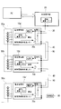
- FIG. 1 is a diagram showing a schematic configuration of the battery device according to the first embodiment of the present invention.
- the battery device 100 includes a plurality of battery management units (battery management units) 10a, 10b, and 10c, a central management unit (central management unit) 20, a first communication line 30, a first Two communication lines 40, a column battery group including a plurality of column batteries 50a, 50b, and 50c, and switching elements 60a, 60b, and 60c are provided as main components.
- battery management units battery management units
- central management unit central management unit
- switching elements 60a, 60b, and 60c are provided as main components.
- the row batteries 50a, 50b, and 50c are basically configured such that a plurality of battery cells or battery cells are connected in series. Each battery cell is provided with a voltage sensor (not shown) for detecting the voltage of the battery cell and a temperature sensor (not shown) for detecting the temperature. The detection results of the voltage sensor and the temperature sensor are output to the battery management unit 10 provided corresponding to each column battery 50. As shown in FIG. 1, in the present embodiment, the column battery 50 includes four battery cells as one column battery, but is not limited thereto. Moreover, the said secondary battery is a lithium ion battery and a lead acid battery, for example.
- the battery management units 10a, 10b, and 10c are connected in a daisy chain by the second communication line 40, and are any one of the plurality of battery management units 10a, 10b, and 10c located at the end.
- the battery management unit 10 a and the central management unit 20 are connected by a first communication line 30.
- the second communication line 40 between the battery management units has a plurality of connection switching units (connection switching means) 60a that switches connection and non-connection between the battery management units. , 60b, and 60c are provided. In the initial state, all the connection switching units 60a, 60b, and 60c are in a disconnected state.
- Each battery management unit 10a, 10b, and 10c stores the determined identification information when the identification information of the battery management unit 10a, 10b, and 10c is determined in communication with the central management unit 20, and the other one located downstream of itself.
- the connection switching unit with the battery management unit is set to the connection state, and the other battery management unit and the central management unit 20 are in a communicable state.
- the battery management unit 10a when the battery management unit 10a receives a first request that is an identification information allocation request from the central management unit 20 (details will be described later), the battery management unit 10a sends a first response including the identification information held by itself to the central management unit. 20, and the connection switching unit 60 a between the other battery management unit 10 b located one downstream from itself is connected, and the other battery management unit 10 b and the central management unit 20 can communicate with each other.
- the central management unit 20 side when viewed from the battery management unit 10a connected to the central management unit 20 by the first connection line, the central management unit 20 side is the upstream side, and the opposite side of the central management unit 20 is the downstream side. Define.
- the central management unit 20 assigns unique identification information to each of the battery management units 10a, 10b, and 10c, and the column battery 50a notified from the battery management units 10a, 10b, and 10c after the identification information is given. , 50b, 50c are acquired and managed. In the present embodiment, the central management unit 20 assigns the unique identification information in ascending order.
- the central management unit 20 transmits a first request for requesting assignment of identification information to the battery management unit 10a via the first communication line 30 at the start of giving identification information.
- the central management unit 20 stores the identification information included in the first response and the battery management unit 10a in association with each other. Then, a second request including the next identification information (for example, an identification number) is generated, and this second request is transmitted to the other battery management unit 10b connected by the operation of the battery management unit 10a.
- the next identification information for example, an identification number
- the central management unit 20 When the central management unit 20 receives the second response from the battery management unit 10b, the central management unit 20 stores the identification information included in the second response and the battery management unit 10b in association with each other and the next information of the identification information. Is generated, and the second request is transmitted to the other battery management unit 10c connected by the operation of the battery management unit 10b. In addition, the central management unit 20 repeatedly transmits the second request a predetermined number of times (for example, three times), and if the second response is not received, the central management unit 20 regards that there is no battery management unit that returns the second response. Complete the allocation of identification information.
- the central management unit 20 assigns the identification information in the order of the battery management units 10a, 10b, and 10c, and the identification information of the battery management units 10a, 10b, and 10c and the battery management units 10a, 10b, and 10c. Are stored in association with each other.
- the central management unit 20 stores the number of battery management units connected in advance, and the number of battery management units 10 in which the number of identification information assigned to each battery management unit is stored in advance when the identification information is given. It is also possible to output an error when it is different from.
- the number of connections of the battery management unit may be arbitrarily rewritten by the user, or may be rewritten using a dedicated tool such as software.
- the central management unit 20 When the central management unit 20 completes the allocation of the identification information, it starts normal communication with each battery management unit 10. Specifically, after the identification information is given, the central management unit 20 uses the battery management units 10a, 10b to obtain the battery information of the column batteries 50a, 50b, 50c connected to the battery management units 10a, 10b, 10c. 10c and manage.
- the battery information is, for example, a voltage value received from a voltage sensor provided in each column battery and a temperature value received from a temperature sensor.
- the battery state of each column battery is managed by the central management unit 20, and for example, when an abnormality occurs in any of the column batteries (abnormality of voltage between terminals, overcurrent, etc.), the error information is stored in the center.
- the data is output to a PC or the like interconnected with the management unit 20.
- a first request for requesting assignment of identification information is generated in the central management unit 20 and transmitted to the battery management unit 10 a connected via the first communication line 30.
- a first response that is a response including identification information (eg, “0001”) of the battery management unit 10a is generated and transmitted to the central management unit 20,
- the connection switching unit 60a is connected to the battery management unit 10b located on the downstream side of the battery management unit 10a so that the battery management unit 10b and the central management unit 20 can communicate with each other.
- the identification information of the battery management unit 10a included in the first response and the battery management unit 10a are stored in association with each other.
- the central management unit 20 transmits a second request including the next identification information “0002” generated based on the predetermined rule from the identification information “0001” of the battery management unit 10a to the battery management unit 10b.
- the In the battery management unit 10b that has received the second request the identification information “0002” included in the received second request is stored as the identification information, and the second response for notifying that the battery management unit 10b has stored is the central management unit. 20 and a connection switching unit 60b between the battery management unit 10c and one downstream side of the battery management unit 10b is connected. As a result, the identification information “0003” is assigned by the same procedure in the battery management unit 10c.
- the battery management unit 10a and the central management unit 20 are connected by the first communication line 30, and at the time of providing identification information, the first communication line. 30.
- Identification information is given to the most upstream battery management unit 10a connected to the central management unit 20 via 30, and then another battery management unit located one downstream by the most upstream battery management unit 10a.
- the connection switching unit 60a between 10b and 10b is connected, the other battery management unit 10b and the central management unit 20 can communicate with each other. In this way, the identification information is assigned in accordance with the physical arrangement order of the batteries by giving the identification information in order from the battery management unit 10a located on the upstream side by the central management unit 20.
- the battery management unit 20 Since the central management unit 20 stores the number of connections of the battery management unit in advance, the battery management unit 20 compares the number of connections of the battery management unit stored in advance with the number of assigned identification information. The shortage of 10 connections can be output by a simple method.
- the battery device is premised on processing by hardware, but is not limited to such a configuration.
- a configuration in which processing is separately performed by software (battery device control program) based on output signals from each sensor is also possible.
- the battery device includes a main storage device such as a CPU and a RAM, and a computer-readable recording medium on which a program for realizing all or part of the above processing is recorded.
- the CPU reads out the program recorded in the storage medium and executes information processing / arithmetic processing, thereby realizing processing similar to that of the hardware device described above.
- the computer-readable recording medium means a magnetic disk, a magneto-optical disk, a CD-ROM, a DVD-ROM, a semiconductor memory, or the like.
- the computer program may be distributed to the computer via a communication line, and the computer that has received the distribution may execute the program.
- the central management unit 20 stores the number of connections of the battery management unit in advance, but is not limited thereto.
- the number of battery management units connected during operation may be changed by a maintenance tool or the like.
- the central management unit 20 again assigns identification information to each of the battery management units. Thereby, even if the number of connections of the battery management unit is changed during operation, all the battery management units can be managed continuously.
- the battery management unit 10 is provided for each column battery, but is not limited thereto.
- a battery management unit may be provided for each battery cell, or a plurality of battery cells may be grouped and the battery management unit 10 may be provided for each group.
- the present invention is not limited to this, and no upper limit is set.
- the number of times the central management unit 20 repeatedly transmits the second request is three, but is not limited thereto.
- the number of times of repeatedly transmitting the second request may be arbitrarily set by the user.
- the normal voltage range and the temperature limit value of the above-described battery cell terminal voltage can be arbitrarily set by design.
- the assignment of unique identification information performed by the central management unit 20 has been assigned in ascending order, it is not limited to this. For example, it may be assigned in descending order.
- the unique identification information given by the central management unit 20 is assigned in ascending order, but is not limited thereto. For example, it may be assigned in descending order.
- the identification information is assigned to each battery management unit by sequentially connecting the second communication lines 40.
- the battery management units are powered on in order.
- the two are different in that identification information is assigned to each battery management unit in order.
- description of points that are common to the first embodiment will be omitted, and only differences will be described.
- the battery management units 10a ′, 10b ′, and 10c ′ are connected in a daisy chain by the second communication line 40, and among the plurality of battery management units 10a ′, 10b ′, and 10c ′, Any of the battery management units 10 a ′ located at the end and the central management unit 20 are connected by a first communication line 30.
- Each of the battery management units 10a ′, 10b ′, and 10c ′ stores the determined identification information when the identification information of the battery management unit 10a ′ itself is determined in communication with the central management unit 20.
- the other battery management unit 10b 'located on the downstream side of itself is turned on.
- connection switching unit 70a provided on the third communication line 90 provided separately from the second communication line 40 is set in a connected state, and the battery management unit 10b ′ is connected to the battery management unit 10b ′ via the third communication line 90.
- the central management unit 20 and the battery management unit 10b ′ can communicate with each other via the second communication line 40, and the battery management unit 10b ′ has the same procedure as in the first embodiment described above. Identification information is assigned.
Landscapes
- Engineering & Computer Science (AREA)
- General Chemical & Material Sciences (AREA)
- Manufacturing & Machinery (AREA)
- Chemical & Material Sciences (AREA)
- Chemical Kinetics & Catalysis (AREA)
- Electrochemistry (AREA)
- Power Engineering (AREA)
- Microelectronics & Electronic Packaging (AREA)
- Physics & Mathematics (AREA)
- General Physics & Mathematics (AREA)
- Charge And Discharge Circuits For Batteries Or The Like (AREA)
- Secondary Cells (AREA)
- Battery Mounting, Suspending (AREA)
Abstract
Description
また、例えば、特許第3549676号公報(特許文献2)には、中央装置が識別情報の割付要求メッセージをネットワークを介して接続されている複数の端末に対して定期的に送信し、該ネットワークに新しく接続された端末からこの割付要求メッセージに対する返信を受信した場合に、この新しい端末に新たな識別情報を割り付ける技術が開示されている。
また、上記特許文献2に開示されている発明では、割付要求メッセージが定期的に送信されるため、通信負荷になるという問題があった。
本発明は、1以上の電池セルを備えた列電池が直列に複数接続されてなる列電池群と、前記列電池の各々に対応して設けられ、対応する該列電池の電池状態を管理する複数の電池管理手段と、前記電池管理手段の各々に対して固有の識別情報を付与するとともに、前記電池管理手段から列電池の各々の電池状態情報を取得して管理する中央管理手段と、複数の前記電池管理手段をデイジーチェーンで接続する第2通信線と、複数の前記電池管理手段のうち、端部に位置するいずれかの該電池管理手段と該中央管理手段とを接続する第1通信線と、前記電池管理手段間の前記第2通信線にそれぞれ設けられ、該電池管理手段間の接続及び非接続を切り替える複数の接続切替手段とを備え、初期状態において全ての前記接続切替手段は非接続状態とされており、前記電池管理手段の各々は、前記中央管理手段との通信において自身の識別情報が決定されると、決定された該識別情報を記憶するとともに、自身の一つ下流側に位置する他の該電池管理手段との間の該接続切替手段を接続状態として、他の該電池管理手段と該中央管理手段とを通信可能な状態とする電池装置を提供する。
図1は、本発明の第1の実施形態に係る電池装置の概略構成を示した図である。
図1に示すように、本実施形態に係る電池装置100は、複数の電池管理部(電池管理手段)10a、10b、10c、中央管理部(中央管理手段)20、第1通信線30、第2通信線40、複数の列電池50a、50b、50cからなる列電池群、及びスイッチング素子60a、60b、60cを主な構成として備えている。
まず、識別情報付与開始時、中央管理部20において識別情報の割付を要求する第1要求が生成され、第1通信線30を介して接続される電池管理部10aに送信される。第1要求を受信した電池管理部10aにおいて、該電池管理部10aの持つ識別情報(例えば、「0001」)を含む応答である第1応答が生成されて中央管理部20に送信されるとともに、この電池管理部10aよりも一つ下流側に位置する電池管理部10bとの間の接続切替部60aが接続され、電池管理部10bと中央管理部20とが通信可能な状態とされる。
第2要求を受信した電池管理部10bにおいて、受信した第2要求に含まれる識別情報「0002」が識別情報として記憶され、電池管理部10bが記憶した旨を通知する第2応答が中央管理部20に送信されるとともに、電池管理部10bよりも一つ下流側の電池管理部10cとの間の接続切替部60bが接続される。
これにより、電池管理部10cにおいても同様の手順により識別情報「0003」が割り振られる。
また、このときに、降順または昇順に識別情報を割り当てていくことで、識別情報の並びと列電池の接続順とを一致させることが可能となる。これにより、例えば、列電池に異常が発生した場合には、いずれの列電池及び電池セルで異常が発生したかを、すみやかに認識することが可能となる。
ここでコンピュータ読み取り可能な記録媒体とは、磁気ディスク、光磁気ディスク、CD-ROM、DVD-ROM、半導体メモリ等をいう。また、このコンピュータプログラムを通信回線によってコンピュータに配信し、この配信を受けたコンピュータが当該プログラムを実行するようにしても良い。
次に、本発明の第2の実施形態について、図2を用いて説明する。
上述した第1の実施形態では、第2通信線40を順次接続することにより、各電池管理部に識別情報を割り当てたが、本実施形態では、各電池管理部の電源を順番に投入していくことで、各電池管理部に順番に識別情報を割り当てる点で両者は異なる。
以下、本実施形態の電池装置200について、第1の実施形態と共通する点については説明を省略し、異なる点についてのみ説明する。
これにより、中央管理部20と電池管理部10b´とは第2通信線40を介した通信が可能な状態とされ、上述した第1の実施形態と同様の手順により、電池管理部10b´に識別情報が割り付けられることとなる。電池管理部10b´における識別情報の付与が終了すると、同様に、電池管理部10c´から第3通信線90を介して電源投入を指示する信号が出力され、これにより、電池管理部10c´の電源が投入される。これにより、第2通信線40を介した電池管理部10c´と中央管理部20との通信が可能となり、電池管理部10c´に識別情報が割り付けられる。
このように、各電池管理部10a´、10b´、10c´の電源を順次投入していくことによっても、上述した第1の実施形態と同様に、順番に所望の識別情報を付与することが可能となる。
20 中央管理部
30 第1通信線
40 第2通信線
50a、50b、50c 列電池
60a、60b、60c 接続切替部
70a、70b、70c 接続切替部
90 第3通信線
100 電池装置
Claims (8)
- 1以上の電池セルを備えた列電池が直列に複数接続されてなる列電池群と、
前記列電池の各々に対応して設けられ、対応する該列電池の電池状態を管理する複数の電池管理手段と、
前記電池管理手段の各々に対して固有の識別情報を付与するとともに、前記電池管理手段から列電池の各々の電池状態情報を取得して管理する中央管理手段と、
複数の前記電池管理手段をデイジーチェーンで接続する第2通信線と、
複数の前記電池管理手段のうち、端部に位置するいずれかの該電池管理手段と該中央管理手段とを接続する第1通信線と、
前記電池管理手段間の前記第2通信線にそれぞれ設けられ、該電池管理手段間の接続及び非接続を切り替える複数の接続切替手段と
を備え、
初期状態において全ての前記接続切替手段は非接続状態とされており、
前記電池管理手段の各々は、前記中央管理手段との通信において自身の識別情報が決定されると、決定された該識別情報を記憶するとともに、自身の一つ下流側に位置する他の該電池管理手段との間の該接続切替手段を接続状態として、他の該電池管理手段と該中央管理手段とを通信可能な状態とする電池装置。 - 前記中央管理手段は、識別情報付与開始時において、前記第1通信線を介して接続される前記電池管理手段に対し、識別情報の割付を要求する第1要求を送信し、
前記第1要求を受信した前記電池管理手段は、自身の持つ識別情報を含む第1応答を前記中央管理手段に送信するとともに、自身よりも一つ下流側に位置する他の電池管理手段との間の前記接続切替手段を接続状態にすることで該他の電池管理手段と前記中央管理手段とを通信可能な状態とし、
前記第1応答を受信した前記中央管理手段は、受信した第1応答に含まれる該電池管理手段の識別情報を記憶するとともに、所定の規則に基づいて生成した次の識別情報を含む第2要求を、該他の電池管理手段に送信し、
前記第2要求を受信した該他の電池管理手段は、受信した前記第2要求に含まれる識別情報を自身の識別情報として記憶し、この記憶した旨を通知する第2応答を前記中央管理手段に送信するとともに、自身よりも一つ下流側の電池管理手段との間の接続切替手段を接続状態とする請求項1に記載の電池装置。 - 1以上の電池セルを備えた列電池が直列に複数接続されてなる列電池群と、
前記列電池の各々に対応して設けられ、対応する該列電池の電池状態を管理する複数の電池管理手段と、
前記電池管理手段の各々に対して固有の識別情報を付与するとともに、前記電池管理手段から列電池の各々の電池状態情報を取得して管理する中央管理手段と、
複数の前記電池管理手段をデイジーチェーンで接続する第2通信線と、
複数の前記電池管理手段のうち、端部に位置するいずれかの該電池管理手段と該中央管理手段とを接続する第1通信線とを備え、
初期状態において、前記第1通信線を介して中央管理手段と接続される最上流に位置する電池管理手段を除いた残りの電池管理手段の電源はオフ状態とされており、
前記電池管理手段の各々は、前記中央管理手段との通信において自身の識別情報が決定されると、決定された該識別情報を記憶するとともに、自身の一つ下流側に位置する他の該電池管理手段に対し、電源を投入させる指令を送信し、他の該電池管理手段と該中央管理手段とを通信可能な状態とする電池装置。 - 前記中央管理手段は、識別情報付与開始時において、前記第1通信線を介して接続される前記電池管理手段に対し、識別情報の割付を要求する第1要求を送信し、
前記第1要求を受信した前記電池管理手段は、自身の持つ識別情報を含む第1応答を前記中央管理手段に送信するとともに、自身よりも一つ下流側に位置する他の電池管理手段に対し、電源を投入させる指令を送信し、該他の電池管理手段と前記中央管理手段とを通信可能な状態とし、
前記第1応答を受信した前記中央管理手段は、受信した第1応答に含まれる該電池管理手段の識別情報を記憶するとともに、所定の規則に基づいて生成した次の識別情報を含む第2要求を、該他の電池管理手段に送信し、
前記第2要求を受信した該他の電池管理手段は、受信した前記第2要求に含まれる識別情報を自身の識別情報として記憶し、この記憶した旨を通知する第2応答を前記中央管理手段に送信するとともに、自身よりも一つ下流側の電池管理手段に対し、電源を投入させる指令を送信する請求項3に記載の電池装置。 - 前記中央管理手段は、昇順または降順で前記識別情報を割り付ける請求項1から請求項4のいずれかに記載の電池装置。
- 前記中央管理手段は、該第2応答を送信しない前記電池管理手段がなくまるまで前記第2要求を送信する請求項2または請求項4に記載の電池装置。
- 前記中央管理手段は、前記電池管理手段の数を予め記憶しており、前記識別情報付与時において、各前記電池管理手段に付与した識別情報の数が予め記憶している該電池管理手段の数と異なっていた場合にエラー出力を行う請求項1から請求項6のいずれかに記載の電池装置。
- 前記中央管理手段は、自身が記憶している前記電池管理手段の数が変更された場合に、前記電池管理手段の各々に対して再度識別情報を付与する請求項7に記載の電池装置。
Priority Applications (4)
| Application Number | Priority Date | Filing Date | Title |
|---|---|---|---|
| CN200980148950.6A CN102239621B (zh) | 2008-12-09 | 2009-11-30 | 电池装置 |
| US13/133,323 US8742617B2 (en) | 2008-12-09 | 2009-11-30 | Battery apparatus |
| KR1020117012581A KR101291959B1 (ko) | 2008-12-09 | 2009-11-30 | 전지 장치 |
| EP09831828.0A EP2357713B1 (en) | 2008-12-09 | 2009-11-30 | Battery device |
Applications Claiming Priority (2)
| Application Number | Priority Date | Filing Date | Title |
|---|---|---|---|
| JP2008-313524 | 2008-12-09 | ||
| JP2008313524A JP4796119B2 (ja) | 2008-12-09 | 2008-12-09 | 電池装置 |
Publications (1)
| Publication Number | Publication Date |
|---|---|
| WO2010067724A1 true WO2010067724A1 (ja) | 2010-06-17 |
Family
ID=42242713
Family Applications (1)
| Application Number | Title | Priority Date | Filing Date |
|---|---|---|---|
| PCT/JP2009/070111 Ceased WO2010067724A1 (ja) | 2008-12-09 | 2009-11-30 | 電池装置 |
Country Status (6)
| Country | Link |
|---|---|
| US (1) | US8742617B2 (ja) |
| EP (1) | EP2357713B1 (ja) |
| JP (1) | JP4796119B2 (ja) |
| KR (1) | KR101291959B1 (ja) |
| CN (1) | CN102239621B (ja) |
| WO (1) | WO2010067724A1 (ja) |
Cited By (6)
| Publication number | Priority date | Publication date | Assignee | Title |
|---|---|---|---|---|
| WO2011118711A1 (ja) * | 2010-03-26 | 2011-09-29 | 三菱重工業株式会社 | 電池パックおよび電池制御システム |
| EP2408053A3 (en) * | 2010-07-15 | 2013-05-29 | O2 Micro, Inc. | Assigning addresses to multiple cascade battery modules |
| WO2014162765A1 (ja) * | 2013-04-04 | 2014-10-09 | 株式会社豊田自動織機 | 電池監視システム及び識別情報設定方法 |
| JP2015192580A (ja) * | 2014-03-28 | 2015-11-02 | パナソニックIpマネジメント株式会社 | 蓄電池システム |
| US20220314832A1 (en) * | 2020-02-13 | 2022-10-06 | Lg Energy Solution, Ltd. | Battery control system, battery pack, electric vehicle, and id setting method for the battery control system |
| WO2025225644A1 (ja) * | 2024-04-26 | 2025-10-30 | 株式会社Gsユアサ | デバイス装置、エネルギー貯蔵システム |
Families Citing this family (37)
| Publication number | Priority date | Publication date | Assignee | Title |
|---|---|---|---|---|
| KR101245279B1 (ko) | 2010-10-11 | 2013-03-19 | 주식회사 엘지화학 | 배터리팩의 멀티 슬레이브에 대한 순차적 아이디 설정방법 및 시스템 |
| JP5481413B2 (ja) * | 2011-02-28 | 2014-04-23 | 株式会社日立製作所 | 蓄電池システムおよび蓄電池モジュール |
| US9608297B2 (en) | 2011-11-16 | 2017-03-28 | Datang Nxp Semiconductors Co., Ltd. | In-cell battery management device |
| DE102012210262A1 (de) * | 2011-11-18 | 2013-05-23 | Robert Bosch Gmbh | Batterie mit einer Batteriezelle mit externem und integriertem Temperatursensor und Verfahren zum Betrieb der Batterie |
| US8904049B2 (en) * | 2012-08-23 | 2014-12-02 | Lg Chem, Ltd. | Battery pack monitoring system and method for assigning a binary ID to a microprocessor in the battery pack monitoring system |
| WO2014038180A1 (ja) * | 2012-09-05 | 2014-03-13 | 三洋電機株式会社 | 電源装置および管理装置 |
| JP5693547B2 (ja) * | 2012-11-20 | 2015-04-01 | 三菱重工業株式会社 | 電池管理装置およびその制御方法ならびにプログラム、それを備えた電池監視システム |
| DE102012113078A1 (de) * | 2012-12-23 | 2014-06-26 | Prosol Invest Deutschland Gmbh | Überwachungseinrichtung |
| KR101768251B1 (ko) | 2013-04-05 | 2017-08-30 | 삼성에스디아이 주식회사 | 배터리 모듈의 정상 연결 상태 확인을 제공하는 배터리 팩 |
| TWI526956B (zh) | 2013-04-30 | 2016-03-21 | 台灣立凱綠能移動股份有限公司 | 大型電動車電源架構及其電池箱輪休排序控制方法 |
| KR102210890B1 (ko) * | 2013-06-05 | 2021-02-02 | 삼성에스디아이 주식회사 | 배터리 시스템, 및 배터리 시스템의 관리 방법 |
| JP2015008040A (ja) * | 2013-06-24 | 2015-01-15 | 株式会社東芝 | 二次電池装置及びモジュール接続判別方法 |
| KR102071404B1 (ko) * | 2013-08-12 | 2020-01-30 | 현대모비스 주식회사 | Bms의 페일 세이프 장치 및 방법 |
| JP5669902B1 (ja) * | 2013-08-30 | 2015-02-18 | 三菱電機株式会社 | 空調機制御システム、センサ機器制御方法及びプログラム |
| DE102014200321A1 (de) | 2014-01-10 | 2015-07-16 | Robert Bosch Gmbh | Verfahren zum Starten eines Batteriemanagementsystems |
| WO2015122746A1 (ko) * | 2014-02-17 | 2015-08-20 | 주식회사 엘지화학 | 고장 발생 여부의 분석이 가능한 신호를 출력하는 배터리 관리 시스템 및 이를 포함하는 배터리 구동 시스템 |
| JP6448655B2 (ja) | 2014-02-17 | 2019-01-09 | エルジー・ケム・リミテッド | 故障発生如何を分析可能な信号を出力するバッテリー管理システム及びそれを含むバッテリー駆動システム |
| WO2015126225A1 (ko) * | 2014-02-24 | 2015-08-27 | 주식회사 엘지화학 | 주파수 변조를 이용하여 식별자를 설정하는 배터리 관리 유닛 및 방법 |
| JP6513711B2 (ja) | 2014-02-24 | 2019-05-15 | エルジー・ケム・リミテッド | 周波数変調を用いて識別子を設定するバッテリー管理ユニット及び方法 |
| JP6160532B2 (ja) | 2014-03-26 | 2017-07-12 | 株式会社豊田自動織機 | 電池監視装置 |
| DE102014215730A1 (de) * | 2014-08-08 | 2016-02-11 | Robert Bosch Gmbh | Batteriezellenmodul mit Kommunikationsvorrichtung für einen Datenaustausch zwischen mehreren gleichartigen in Reihe geschalteten Batteriezellenmodulen |
| KR101779655B1 (ko) * | 2015-02-26 | 2017-09-18 | 엘에스산전 주식회사 | 에너지 저장 시스템의 동기화 방법 |
| CN106571495B (zh) * | 2015-10-08 | 2019-03-19 | 松下知识产权经营株式会社 | 蓄电系统和蓄电方法 |
| CN106602623B (zh) * | 2015-10-16 | 2020-03-24 | 北京宝沃汽车有限公司 | 电池管理系统及其更新方法、电动汽车控制系统和电动车 |
| CN108463918B (zh) * | 2015-10-30 | 2021-09-03 | 株式会社东芝 | 电池控制装置以及电池系统 |
| DE102016219894B3 (de) | 2016-10-12 | 2018-03-01 | Audi Ag | Batterie sowie Kraftfahrzeug mit einer Batterie |
| JP6922337B2 (ja) * | 2017-03-31 | 2021-08-18 | 株式会社豊田中央研究所 | 電源装置及びそれにおけるsoc推定方法 |
| KR102202615B1 (ko) * | 2017-09-25 | 2021-01-12 | 주식회사 엘지화학 | 복수의 슬레이브 배터리 관리 유닛들에게 식별 정보를 할당하기 위한 장치 |
| US11223074B2 (en) | 2017-10-16 | 2022-01-11 | Neapco Intellectual Property Holdings, Llc | Battery cell monitoring system |
| KR102255494B1 (ko) | 2018-02-22 | 2021-05-24 | 주식회사 엘지에너지솔루션 | 복수의 슬레이브 관리 모듈에게 id를 할당하기 위한 무선 배터리 제어 시스템, 방법 및 배터리 팩 |
| WO2019164203A1 (ko) * | 2018-02-22 | 2019-08-29 | 주식회사 엘지화학 | 복수의 슬레이브 관리 모듈에게 id를 할당하기 위한 무선 배터리 제어 시스템, 방법 및 배터리 팩 |
| GB2576001B (en) * | 2018-07-31 | 2022-08-10 | Petalite Ltd | Battery controller communication systems |
| KR102680186B1 (ko) * | 2018-10-10 | 2024-06-28 | 주식회사 엘지에너지솔루션 | Pwm 신호를 이용한 bms 식별자 자동 할당 시스템 및 자동 할당 방법 |
| CN111169321B (zh) * | 2018-11-09 | 2021-09-07 | 宝沃汽车(中国)有限公司 | 汽车、电池包、电池信息采集系统的控制方法 |
| KR102510886B1 (ko) | 2018-11-23 | 2023-03-16 | 삼성에스디아이 주식회사 | 슬레이브 모듈 및 이를 포함하는 번호 할당 시스템 |
| TWI718661B (zh) | 2019-09-10 | 2021-02-11 | 立錡科技股份有限公司 | 電池系統及其中之電池模組及電池控制電路 |
| CN218039399U (zh) * | 2022-08-11 | 2022-12-13 | 湖北亿纬动力有限公司 | 一种电池系统 |
Citations (5)
| Publication number | Priority date | Publication date | Assignee | Title |
|---|---|---|---|---|
| JP2002110259A (ja) * | 2000-09-28 | 2002-04-12 | Hitachi Ltd | 蓄電装置 |
| JP2003209932A (ja) * | 2002-01-10 | 2003-07-25 | Panasonic Ev Energy Co Ltd | 電池電源装置とその制御方法及びアドレス設定方法 |
| JP2004193643A (ja) | 2002-12-06 | 2004-07-08 | Nec Commun Syst Ltd | Ipアドレス自動割付方法/プログラム、端末装置 |
| JP3549676B2 (ja) | 1996-07-24 | 2004-08-04 | 富士通株式会社 | 端末id自動割付方式 |
| JP2009089486A (ja) * | 2007-09-28 | 2009-04-23 | Hitachi Ltd | 多直列電池制御システム |
Family Cites Families (7)
| Publication number | Priority date | Publication date | Assignee | Title |
|---|---|---|---|---|
| JPH08140204A (ja) * | 1994-11-08 | 1996-05-31 | Matsushita Electric Ind Co Ltd | 組電池の監視装置 |
| US5656915A (en) * | 1995-08-28 | 1997-08-12 | Eaves; Stephen S. | Multicell battery pack bilateral power distribution unit with individual cell monitoring and control |
| JP3196612B2 (ja) * | 1995-11-16 | 2001-08-06 | 松下電器産業株式会社 | 組電池の監視装置 |
| JP4122574B2 (ja) | 1998-06-23 | 2008-07-23 | 双葉電子工業株式会社 | デイジーチェイン接続機器およびデイジーチェイン接続機器のアドレス設定方法 |
| EP1806592B1 (en) * | 2005-12-29 | 2017-01-18 | Semiconductor Components Industries, LLC | Method and system for monitoring battery stacks |
| DK2024519T3 (da) * | 2006-05-15 | 2021-12-13 | A123 Systems Llc | Multikonfigurerbart, skalerbart, redundant batterimodul med multipel fejltolerance |
| CN201117741Y (zh) * | 2007-06-07 | 2008-09-17 | 上海工程技术大学 | 一种汽车智能蓄电池装置 |
-
2008
- 2008-12-09 JP JP2008313524A patent/JP4796119B2/ja active Active
-
2009
- 2009-11-30 CN CN200980148950.6A patent/CN102239621B/zh active Active
- 2009-11-30 US US13/133,323 patent/US8742617B2/en active Active
- 2009-11-30 WO PCT/JP2009/070111 patent/WO2010067724A1/ja not_active Ceased
- 2009-11-30 KR KR1020117012581A patent/KR101291959B1/ko active Active
- 2009-11-30 EP EP09831828.0A patent/EP2357713B1/en active Active
Patent Citations (5)
| Publication number | Priority date | Publication date | Assignee | Title |
|---|---|---|---|---|
| JP3549676B2 (ja) | 1996-07-24 | 2004-08-04 | 富士通株式会社 | 端末id自動割付方式 |
| JP2002110259A (ja) * | 2000-09-28 | 2002-04-12 | Hitachi Ltd | 蓄電装置 |
| JP2003209932A (ja) * | 2002-01-10 | 2003-07-25 | Panasonic Ev Energy Co Ltd | 電池電源装置とその制御方法及びアドレス設定方法 |
| JP2004193643A (ja) | 2002-12-06 | 2004-07-08 | Nec Commun Syst Ltd | Ipアドレス自動割付方法/プログラム、端末装置 |
| JP2009089486A (ja) * | 2007-09-28 | 2009-04-23 | Hitachi Ltd | 多直列電池制御システム |
Non-Patent Citations (1)
| Title |
|---|
| See also references of EP2357713A4 |
Cited By (10)
| Publication number | Priority date | Publication date | Assignee | Title |
|---|---|---|---|---|
| WO2011118711A1 (ja) * | 2010-03-26 | 2011-09-29 | 三菱重工業株式会社 | 電池パックおよび電池制御システム |
| US8958934B2 (en) | 2010-03-26 | 2015-02-17 | Mitsubishi Heavy Industries, Ltd. | Battery pack and battery control system |
| EP2408053A3 (en) * | 2010-07-15 | 2013-05-29 | O2 Micro, Inc. | Assigning addresses to multiple cascade battery modules |
| WO2014162765A1 (ja) * | 2013-04-04 | 2014-10-09 | 株式会社豊田自動織機 | 電池監視システム及び識別情報設定方法 |
| JP2014202581A (ja) * | 2013-04-04 | 2014-10-27 | 株式会社豊田自動織機 | 電池監視システム及び識別情報設定方法 |
| US10001527B2 (en) | 2013-04-04 | 2018-06-19 | Kabushiki Kaisha Toyota Jidoshokki | Battery-monitoring system and identifying-information setting method |
| JP2015192580A (ja) * | 2014-03-28 | 2015-11-02 | パナソニックIpマネジメント株式会社 | 蓄電池システム |
| US20220314832A1 (en) * | 2020-02-13 | 2022-10-06 | Lg Energy Solution, Ltd. | Battery control system, battery pack, electric vehicle, and id setting method for the battery control system |
| US12049154B2 (en) * | 2020-02-13 | 2024-07-30 | Lg Energy Solution, Ltd. | Battery control system, battery pack, electric vehicle, and id setting method for the battery control system |
| WO2025225644A1 (ja) * | 2024-04-26 | 2025-10-30 | 株式会社Gsユアサ | デバイス装置、エネルギー貯蔵システム |
Also Published As
| Publication number | Publication date |
|---|---|
| JP2010141971A (ja) | 2010-06-24 |
| US8742617B2 (en) | 2014-06-03 |
| CN102239621A (zh) | 2011-11-09 |
| JP4796119B2 (ja) | 2011-10-19 |
| US20110273023A1 (en) | 2011-11-10 |
| CN102239621B (zh) | 2014-04-23 |
| EP2357713B1 (en) | 2018-05-02 |
| EP2357713A1 (en) | 2011-08-17 |
| EP2357713A4 (en) | 2014-05-07 |
| KR20110092289A (ko) | 2011-08-17 |
| KR101291959B1 (ko) | 2013-08-09 |
Similar Documents
| Publication | Publication Date | Title |
|---|---|---|
| JP4796119B2 (ja) | 電池装置 | |
| CN110581577B (zh) | 一种储能电池即插即用控制方法 | |
| CN115664932B (zh) | 能量块并联通讯方法及装置 | |
| CN101667668A (zh) | 多单元电池系统及管理编号赋予方法 | |
| KR20170051071A (ko) | 배터리의 id 할당 장치 및 방법 | |
| JP6654518B2 (ja) | 情報処理システム、電池モジュール、制御方法、及びプログラム | |
| JP5838756B2 (ja) | Id付与システム、及びid付与方法 | |
| CN102842939A (zh) | 一种电池管理系统及电池管理方法 | |
| JP2008099482A (ja) | 組電池ブロックならびに電池パックシステムおよびそのアドレス設定方法 | |
| WO2026066526A1 (zh) | 一种电池包、电池包的控制方法、电子设备及存储介质 | |
| KR20150067832A (ko) | 배터리 모듈화 구조에서의 모듈 정보 갱신 방법 | |
| KR102101910B1 (ko) | 배터리 모듈의 id 중복 할당 방지방법 | |
| JP2020018153A (ja) | 電源装置、電源装置の制御装置、電源装置の制御方法、及び電源システム | |
| CN115498739B (zh) | 储能系统及其控制方法 | |
| CN118748670A (zh) | 地址分配方法、电池管理系统和电子设备 | |
| WO2025112153A1 (zh) | 电池数据更新装置、电池数据更新方法、设备及存储介质 | |
| JP2017163708A (ja) | 制御装置、および電源システムの識別情報付与方法 | |
| TW202326464A (zh) | 儲能裝置、儲能裝置歷史使用資料同步系統與電子系統 | |
| JP6783994B2 (ja) | 電圧測定装置、電圧検出回路、及び電圧検出方法 | |
| JPWO2018155271A1 (ja) | 電池モジュール、制御方法、プログラム、及び情報処理システム | |
| KR20230174323A (ko) | 복수의 배터리 셀들을 적어도 하나의 클러스터로 구분하기 위한 배터리 팩 | |
| JP2015072222A (ja) | 電池監視装置 | |
| CN119342038B (zh) | 基于bmscan通信的并机自动堆叠编址方法与系统 | |
| JP2000040013A (ja) | 二重化通信システムの回線異常検出方法 | |
| US11831464B2 (en) | Network routing device and method |
Legal Events
| Date | Code | Title | Description |
|---|---|---|---|
| WWE | Wipo information: entry into national phase |
Ref document number: 200980148950.6 Country of ref document: CN |
|
| 121 | Ep: the epo has been informed by wipo that ep was designated in this application |
Ref document number: 09831828 Country of ref document: EP Kind code of ref document: A1 |
|
| ENP | Entry into the national phase |
Ref document number: 20117012581 Country of ref document: KR Kind code of ref document: A |
|
| WWE | Wipo information: entry into national phase |
Ref document number: 2009831828 Country of ref document: EP |
|
| NENP | Non-entry into the national phase |
Ref country code: DE |
|
| WWE | Wipo information: entry into national phase |
Ref document number: 13133323 Country of ref document: US |