WO2010071041A1 - インクジェット描画装置 - Google Patents
インクジェット描画装置 Download PDFInfo
- Publication number
- WO2010071041A1 WO2010071041A1 PCT/JP2009/070461 JP2009070461W WO2010071041A1 WO 2010071041 A1 WO2010071041 A1 WO 2010071041A1 JP 2009070461 W JP2009070461 W JP 2009070461W WO 2010071041 A1 WO2010071041 A1 WO 2010071041A1
- Authority
- WO
- WIPO (PCT)
- Prior art keywords
- maintenance unit
- maintenance
- unit
- head module
- drawing apparatus
- Prior art date
- Legal status (The legal status is an assumption and is not a legal conclusion. Google has not performed a legal analysis and makes no representation as to the accuracy of the status listed.)
- Ceased
Links
Images


Classifications
-
- B—PERFORMING OPERATIONS; TRANSPORTING
- B41—PRINTING; LINING MACHINES; TYPEWRITERS; STAMPS
- B41J—TYPEWRITERS; SELECTIVE PRINTING MECHANISMS, i.e. MECHANISMS PRINTING OTHERWISE THAN FROM A FORME; CORRECTION OF TYPOGRAPHICAL ERRORS
- B41J2/00—Typewriters or selective printing mechanisms characterised by the printing or marking process for which they are designed
- B41J2/005—Typewriters or selective printing mechanisms characterised by the printing or marking process for which they are designed characterised by bringing liquid or particles selectively into contact with a printing material
- B41J2/01—Ink jet
- B41J2/135—Nozzles
- B41J2/165—Prevention or detection of nozzle clogging, e.g. cleaning, capping or moistening for nozzles
- B41J2/16517—Cleaning of print head nozzles
- B41J2/16535—Cleaning of print head nozzles using wiping constructions
- B41J2/16544—Constructions for the positioning of wipers
- B41J2/16547—Constructions for the positioning of wipers the wipers and caps or spittoons being on the same movable support
-
- B—PERFORMING OPERATIONS; TRANSPORTING
- B41—PRINTING; LINING MACHINES; TYPEWRITERS; STAMPS
- B41J—TYPEWRITERS; SELECTIVE PRINTING MECHANISMS, i.e. MECHANISMS PRINTING OTHERWISE THAN FROM A FORME; CORRECTION OF TYPOGRAPHICAL ERRORS
- B41J2/00—Typewriters or selective printing mechanisms characterised by the printing or marking process for which they are designed
- B41J2/005—Typewriters or selective printing mechanisms characterised by the printing or marking process for which they are designed characterised by bringing liquid or particles selectively into contact with a printing material
- B41J2/01—Ink jet
- B41J2/135—Nozzles
- B41J2/165—Prevention or detection of nozzle clogging, e.g. cleaning, capping or moistening for nozzles
- B41J2/16585—Prevention or detection of nozzle clogging, e.g. cleaning, capping or moistening for nozzles for paper-width or non-reciprocating print heads
-
- B—PERFORMING OPERATIONS; TRANSPORTING
- B41—PRINTING; LINING MACHINES; TYPEWRITERS; STAMPS
- B41J—TYPEWRITERS; SELECTIVE PRINTING MECHANISMS, i.e. MECHANISMS PRINTING OTHERWISE THAN FROM A FORME; CORRECTION OF TYPOGRAPHICAL ERRORS
- B41J3/00—Typewriters or selective printing or marking mechanisms characterised by the purpose for which they are constructed
- B41J3/28—Typewriters or selective printing or marking mechanisms characterised by the purpose for which they are constructed for printing downwardly on flat surfaces, e.g. of books, drawings, boxes, envelopes, e.g. flat-bed ink-jet printers
Definitions
- the present invention relates to an ink jet drawing apparatus, and more particularly to an ink jet drawing apparatus capable of performing head maintenance with high accuracy without the need to lengthen and enlarge the stage on the apparatus base.
- a droplet discharge head (hereinafter simply referred to as a head).
- a head There is an increasing need to land various droplets discharged from a very fine target having an error of about 1 ⁇ m on a workpiece (recording material).
- the head position be set at an accurate position. Further, it is necessary to perform maintenance work so that the landing position of the liquid droplets is landed at an appropriate position by appropriately maintaining the head.
- Patent Document 1 discloses that a maintenance area is provided adjacent to a drawing area in an apparatus main body, and a carriage holding the head is moved to the maintenance area during maintenance. Yes.
- the head is fixed on the apparatus base, and a plurality of types of maintenance units are provided on a stage installed on the same apparatus base so that a predetermined area including a position directly below the head can be moved horizontally.
- a desired maintenance unit is moved to just below the head by moving the stage.
- the maintenance unit generally includes a capping unit for preventing the nozzle surface of the head from drying, a sucking unit for forcibly sucking ink from the nozzle, a flushing tray for storing ink forcibly ejected from the nozzle, a nozzle surface It is necessary to install a plurality of types of maintenance units on the stage so that they can be used for a plurality of types, such as a wiping unit for removing dirt such as residual ink adhered to the stage. Therefore, there is a problem that the stage becomes long and large because the installation location must be secured on the stage.
- both the drawing table and the maintenance unit need to be positioned with high accuracy with respect to the head, the movement must also be performed with high accuracy.
- a stage for performing high-precision movement is extremely expensive and not only high in cost, but also needs to move the stage for a long distance in order to use a predetermined maintenance unit.
- the present invention eliminates the need to lengthen and enlarge the stage, suppresses the occurrence of head misalignment due to vibration, and performs high-precision maintenance by positioning the maintenance unit on the head. It is an object of the present invention to provide an inkjet drawing apparatus that can be used.
- a head module configured to hold a droplet discharge head having a nozzle for discharging droplets and to be unable to move in a horizontal direction, and to support a recording material on an upper surface.
- An ink jet printing apparatus configured to perform predetermined drawing by discharging droplets from the droplet discharge head toward the recording material, the drawing table being configured to be movable in a horizontal direction in a predetermined region including directly under the module A drawing device, A predetermined region including a position directly below the head module is configured to be movable, and a maintenance unit for performing maintenance of the droplet discharge head is transported to a position immediately below the head module to be positioned with respect to the droplet discharge head.
- Maintenance unit transport means Maintenance unit selection and installation means for selecting any one maintenance unit from among a plurality of types of maintenance units for performing maintenance of the droplet discharge head, and installing the selected maintenance unit on the maintenance unit transport means;
- An ink jet drawing apparatus comprising:
- the invention according to claim 2 comprises a relative position measuring means for measuring a relative position between the head module and the maintenance unit conveyed by the maintenance unit conveying means, 2.
- a third aspect of the present invention is the ink jet drawing apparatus according to the first or second aspect, wherein the maintenance unit selecting and installing means is constituted by a robot arm capable of holding one maintenance unit at a tip. .
- the maintenance unit selecting and installing means is provided so as to be slidable and movable up and down along a gantry provided so as to straddle the maintenance unit conveying means, and one maintenance unit is provided at the lower end.
- the invention according to claim 5 is the ink jet drawing apparatus according to any one of claims 1 to 4, further comprising a maintenance unit arrangement table in which the plurality of types of maintenance units are arranged on an upper surface.
- the invention according to claim 6 is characterized in that the head module and the drawing table are installed on a common surface plate, and the maintenance unit selection and installation means is not installed on the surface plate.
- An inkjet drawing apparatus according to any one of claims 1 to 5.
- the drawing table and the maintenance unit transporting unit are movable in a horizontal direction in a predetermined area including immediately below the head module, and are along a vertical direction with respect to the upper surface of the drawing table.
- the inkjet drawing apparatus according to any one of claims 1 to 6, wherein the inkjet drawing apparatus is provided on a common stage configured to be rotatable about a direction.
- the invention according to claim 8 is configured such that the drawing table is retracted to a position where it does not interfere with the maintenance unit during maintenance by the maintenance unit, and an insertion space for the maintenance unit is secured below the head module.
- a head module configured to hold a droplet discharge head having a nozzle for discharging a droplet and to be unable to move in a horizontal direction, and to support a recording material on an upper surface thereof.
- An ink jet printing apparatus configured to perform predetermined drawing by discharging droplets from the droplet discharge head toward the recording material, the drawing table being configured to be movable in a horizontal direction in a predetermined region including directly under the module A drawing device, A predetermined region including a position directly below the head module is configured to be movable, and a maintenance unit for performing maintenance of the droplet discharge head is transported to a position immediately below the head module to be positioned with respect to the droplet discharge head.
- a maintenance unit carrying means is configured by a robot arm that has a maintenance unit installed at a tip thereof, and the tip is movable in a horizontal direction and a vertical direction in a predetermined region including immediately below the head module.
- An inkjet drawing apparatus is configured by a robot arm that has a maintenance unit installed at a tip thereof, and the tip is movable in a horizontal direction and a vertical direction in a predetermined region including immediately below the head module.
- the invention according to claim 10 includes a relative position measuring means for measuring a relative position between the head module and the maintenance unit conveyed by the maintenance unit conveying means, 10.
- the invention according to claim 11 is the ink jet drawing apparatus according to claim 9 or 10, characterized in that the maintenance unit conveying means has a rotary table having a plurality of types of maintenance units installed at the tip.
- the invention according to claim 12 is characterized in that the head module and the drawing table are installed on a common surface plate, and the maintenance unit conveying means is not installed on the surface plate.
- An ink jet drawing apparatus according to any one of claims 9 to 11.
- the drawing table is configured to retract to a position where it does not interfere with the maintenance unit during maintenance by the maintenance unit, and to secure a space for inserting the maintenance unit below the head module.
- an inkjet drawing apparatus that can be provided can be provided.
- FIG. 3 is a plan view for explaining a maintenance operation by the ink jet drawing apparatus according to the first embodiment.
- FIG. 3 is a plan view for explaining a maintenance operation by the ink jet drawing apparatus according to the first embodiment.
- FIG. 3 is a plan view for explaining a maintenance operation by the ink jet drawing apparatus according to the first embodiment.
- FIG. 3 is a plan view for explaining a maintenance operation by the ink jet drawing apparatus according to the first embodiment.
- FIG. 3 is a plan view for explaining a maintenance operation by the ink jet drawing apparatus according to the first embodiment.
- FIG. 3 is a plan view for explaining a maintenance operation by the ink jet drawing apparatus according to the first embodiment.
- Side view showing a second embodiment of an ink jet drawing apparatus Top view showing a second embodiment of an ink jet drawing apparatus The top view explaining the maintenance operation
- Side view of an ink jet drawing apparatus provided with another aspect of maintenance unit selection / installation means The top view of the inkjet drawing apparatus provided with the other aspect of the maintenance unit selection installation means
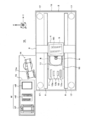
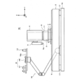
- FIG. 1 is a side view showing a first embodiment of an ink jet drawing apparatus according to the present invention
- FIG. 2 is a plan view thereof.
- a stone gantry 3 is installed on a stone surface plate 2 having a rectangular shape in plan view along the X direction in the figure.
- the gantry 3 is indicated by a one-dot chain line in FIG.
- the gantry 3 is provided with a Z stage 4 that can be moved up and down along the Z direction in the figure.
- the Z stage 4 can be moved up and down only with respect to the gantry 3 and cannot move in the horizontal direction.
- a head module 5 is installed at the lower end of the Z stage 4.
- FIG. 3 is a bottom view of the head module 5.
- the head module 5 includes a droplet discharge head (hereinafter simply referred to as a head) 51 in which a large number of nozzles 51 a for discharging droplets are arranged. By arranging and holding them in a staggered manner along the arrangement direction of 51a, a line head that is elongated along the X direction in the figure is constituted. At appropriate positions at the four corners of the bottom surface of the base plate 50, cross-shaped position confirmation markers 52 are formed. Further, a straight line connecting the position confirmation markers 52, 52 formed at a distance from two locations along the X direction is formed to be parallel to the nozzle row direction of each head 51.
- the head module 5 is arranged such that the nozzle surface of each head 51 faces downward and can face the surface of a recording material (not shown) arranged below the head module 5 in the Z direction. It is attached to the lower end of the Z stage 4 via a ⁇ rotation mechanism (not shown) for rotating in the ⁇ direction about the direction along the axis.
- a first camera 6 for viewing the lower side of the Z stage 4 is integrally attached to the side surface of the Z stage 4.
- the first camera 6 is a maintenance unit position confirmation camera composed of a CCD or the like for confirming the position and orientation of a maintenance unit M, which will be described later, disposed below, and the lens surface 6a is placed below the lens surface 6a. It is attached to the Z stage 4 so that it can be raised and lowered independently. The first camera 6 is moved up and down in order to confirm a marker formed at a predetermined position when recognizing an image of a position of a maintenance unit M described later.
- a transport stage 7 for transporting a recording material (not shown), and a ⁇ rotation mechanism for rotating the transport stage 7 in the ⁇ direction about the direction along the Z direction.
- the X direction and the Y direction are directions orthogonal to each other on a horizontal plane parallel to the upper surface of the surface plate 2, the X direction indicates the sub-scanning direction, and the Y direction indicates the main scanning direction.
- the Z direction is a direction perpendicular to the upper surface of the surface plate 2, and is a direction orthogonal to both the X direction and the Y direction.
- the transport stage 7 is a rectangular flat plate provided on the ⁇ rotation mechanism 8, and has a drawing table 11 on the upper surface thereof and a second for visually checking the drawing table 11 close to the drawing table 11.
- the camera 12 is integrally installed.
- the upper surface of the drawing table 11 is a horizontal plane parallel to the upper surface of the surface plate 2, and a recording material (not shown) that is a target for performing predetermined drawing by landing droplets discharged from the head module 5. Is placed and supported.
- the drawing table 11 is formed so as to protrude higher than the surface of the transfer stage 7.
- the rotation center of the ⁇ rotation mechanism 8 is set at the center position of the drawing table 11.
- the second camera 12 is a head position confirmation camera comprising a CCD or the like for confirming the position and orientation of the head module 5 positioned above, and the conveyance stage with the lens surface 12a facing upward. 7 is placed horizontally at a predetermined position on the upper surface of 7 and is fixedly attached to the transfer stage 7.
- the upper surface of the transfer stage 7 protrudes further to the side along the Y direction in the drawing than the installation space of the drawing table 11 and the second camera 12, and a maintenance unit described later is provided by the upper surface space of the protruding portion.
- a maintenance unit installation portion 13 for installing M is formed.
- the maintenance unit installation unit 13 has a minimum space sufficient to install any one type of maintenance unit M among the plurality of types of maintenance units M. For this reason, the maintenance stage M can be maintained by a plurality of types of maintenance units M, but the transfer stage 7 is not unnecessarily increased in size, and the maintenance unit M installed thereon is moved directly below the head module 5. The required travel distance is always minimal.
- This height difference is set to be approximately the same as the maximum height of the maintenance unit M that can be installed in the maintenance unit installation unit 13, so that the maintenance unit is placed between the head module 5 and the maintenance unit installation unit 13 during a maintenance operation described later.
- a space where M can be inserted can be secured, and a moving distance when the head module 5 is moved up and down can be shortened.
- the maintenance unit installation unit 13 includes a holding mechanism 13a for holding the installed maintenance unit M so that it cannot be moved during maintenance.
- the specific holding mechanism 13a is not particularly limited.
- a lock mechanism that locks the maintenance unit M so as to be immovable by mechanically locking the maintenance unit M
- an adsorption mechanism that adsorbs the maintenance unit M so that it cannot move due to magnetic force, air suction, or the like. Is mentioned.
- the conveyance stage 7 is rotated in the ⁇ direction by the ⁇ rotation mechanism 8 and moved along the X movement mechanism 10 and the Y movement mechanism 9, thereby including a predetermined portion including a position directly below the head module 5 attached to the Z stage 4.
- the region is configured to be movable in the horizontal direction (X, Y direction and ⁇ direction). Accordingly, the maintenance unit M installed in the maintenance unit installation section 13 on the transport stage 7 can be transported to the position immediately below the head module 5 by the horizontal movement of the transport stage 7.
- the maintenance unit conveying means in the present invention is configured.
- the positions of the transfer stage 7 in the X, Y, and ⁇ directions are detected with high accuracy by an encoder (not shown).
- a maintenance unit installation mechanism 14 for installing the maintenance unit M in the maintenance unit installation section 13 on the transfer stage 7 is disposed on the side of the surface plate 2.
- the maintenance unit installation mechanism 14 is composed of a so-called robot arm having a multi-joint structure, is not installed on the surface plate 2, has a separate structure from the surface plate 2, and is located on the side of the surface plate 2. It is attached to the installed maintenance unit arrangement table 15.
- a plurality of types of maintenance units M (m1, m2, m3) are arranged on the upper surface of the maintenance unit arrangement table 15 so as to be selectively usable.
- the maintenance unit installation mechanism 14 has a hand portion 14a for grasping and holding the maintenance unit M at the tip, and by this hand portion 14a, a plurality of types of maintenance units M ( m1, m2, m3) is selected from one of the maintenance units M (m1, m2, m3) and held, and each joint is driven to drive the maintenance unit installation unit 13 on the transport stage 7. It can be carried to a position and installed on the maintenance unit installation part 13. Therefore, the maintenance unit selection installation means in the present invention is constituted by the maintenance unit installation mechanism 14.
- the surface plate 2 is placed on a device base 16 via a vibration isolation mechanism 17 such as an air suspension.
- the maintenance unit installation mechanism 14 and the maintenance unit arrangement table 15 can be provided on the apparatus base 16 as shown in the figure, but may be installed on the floor surface as a separate body from the apparatus base 16, for example. .
- the maintenance unit installation mechanism 14 since the maintenance unit installation mechanism 14 is not installed on the surface plate 2, there is an effect that it is possible to prevent vibrations generated by driving thereof from being directly transmitted to the surface plate 2. Therefore, even if the maintenance unit installation mechanism 14 is installed on the apparatus base 16, the vibration generated by the drive is suppressed from being directly transmitted to the surface plate 2 by the vibration isolation mechanism 17, and sufficiently attenuated.
- the influence on the attachment state of each head 51 of the head module 5 can be reduced.
- the surface plate 2 does not require an installation space for the maintenance unit installation mechanism 14, the expensive surface plate 2 can be miniaturized to the minimum necessary, and the cost can be reduced.
- FIG. 4 is a block diagram showing a schematic configuration inside the ink jet drawing apparatus 1A.
- a calculation unit that controls the whole, and controls the stage controller 101, the arm controller 102, the image processing unit 103, and the ejection control unit 104, respectively.
- the stage controller 101 controls the driving of the stage drivers 105 and 106 based on the control signal from the arithmetic unit 100, and rotates the head module 5 attached to the Z stage 4 in the ⁇ direction.
- a Z-axis motor 111 for moving the Z stage 4 up and down in the Z direction is driven.
- stage controller 101 controls the driving of the stage drivers 107 to 109 based on the control signal from the arithmetic unit 100 to move the transport stage 7 in the X direction, in order to move it in the Y direction.
- the Y axis motor 113 and the ⁇ axis motor 114 for rotating in the ⁇ direction are driven.
- the arm controller 102 controls the various operations by driving the robot arm which is the maintenance unit installation mechanism 14 based on the control signal from the calculation unit 100.
- the image processing unit 103 controls driving of the camera controller 115 based on a control signal from the calculation unit 100, and a first camera 6 attached to the Z stage 4 and a second camera attached to the transfer stage 7. Twelve imaging operations and processing of the captured image are performed.
- the ejection control unit 104 controls the driving of each head 51 of the head module 5 based on a control signal from the calculation unit 100, and performs an ink dropping process based on predetermined drawing data.
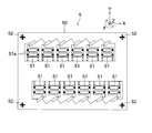
- FIG. 5 shows a plan view of the wiping unit m1, and the wiping unit m1 is arranged on the base 200 having a rectangular shape in plan view, and the wiping members 201 arranged in two rows corresponding to the two head rows of the head module 5. It has.
- Each wipe member 201 is formed in a long tape shape having a width approximately equal to the width of the nozzle surface of the head 51, wound around a roller 202, and is formed on one end of the substrate 200 at the one end of the head 51. They are juxtaposed at the same intervals as the rows.
- the tip of the wipe material 201 can be taken up by a take-up roller 203 disposed at the other end of the substrate 200.
- a motor 204 rotates the take-up roller 203.
- the separation distance between the two pairs of support rollers 205 and 205 is slightly larger than the width (recording width) in the sub-scanning direction including all the heads 51 arranged in the head module 5.
- the surface of the wipe member 201 sandwiched between the roller pairs 205 and 205 forms a wipe surface that rubs the nozzle surface of each head 51 of the head module 5.
- a wiper head 206 corresponding to each head 51 is disposed on the back surface side of the wipe surface, and supports the back surface of the wipe material 201 and causes the wipe surface to contact the nozzle surface of each head 51 during wiping. Reinforces the rubbing effect.
- a cross-shaped positioning marker 207 is formed at appropriate positions at the four corners of the upper surface of the base 200.
- the wiping unit m1 is installed and positioned on the maintenance unit installation unit 13 on the transfer stage 7, and after the wipe members 201 and the head 51 come into contact with each other, the motor 204 is driven to wind the wipe member 201. By winding it around 203, the nozzle surface of each head 51 is rubbed to clean the nozzle surface.
- the power for driving each motor 204 may be supplied from a power cord connected to a power connector (not shown), or as shown in FIG.
- the electrode 13b may be provided so that when the wiping unit m1 is installed, the electrode 13b is electrically connected to an electrode (not shown) provided in the wiping unit m1 to be supplied from the drawing apparatus main body side.
- FIG. 6 shows a plan view of the sucking unit m2, and the sucking unit m2 has a number and arrangement of sucking caps 301 corresponding to each head 51 of the head module 5 on a rectangular base 300 in plan view.
- a sucking pipe 302 is connected to each sucking cap 301.
- the other end of the sucking pipe 302 is connected to a suction pump (not shown), and the air in each sucking cap 301 is sucked by driving the suction pump.
- cross-shaped positioning markers 303 are formed at appropriate positions at the four corners of the upper surface of the base 300.
- the sucking unit m2 is installed and positioned on the maintenance unit installation unit 13 on the transport stage 7, and after each sucking cap 301 and each head 51 come into contact and contact with each other, each sucking unit is driven by a suction pump.
- a suction pump By making the inside of the cap 301 into a negative pressure state, ink is forcibly sucked from the nozzles 51a of the heads 51, and the ink clogging is eliminated and bubbles are discharged.
- the suction pump is not driven, so that the nozzle surface of each head 51 can be sealed and the nozzle 51a can be prevented from drying.
- FIG. 7 is a plan view of the flushing tray m3.
- the flushing tray m3 has a tray 401 large enough to surround all the heads 51 of the head module 5 on a rectangular base 400 in plan view. is doing.
- cross-shaped positioning markers 402 are formed at appropriate positions at the four corners of the upper surface of the base 400.
- the flushing tray m3 is placed and positioned on the maintenance unit installation portion 13 on the transport stage 7, and after being placed below the head module 5, for the purpose of eliminating nozzle clogging and homogenizing each nozzle 51a.
- a droplet forcibly discharged from each nozzle 51 a is received in the tray 401.
- maintenance unit installation mechanism 14 drives the arm and grips the desired maintenance unit M (m1, m2, m3), and then each head 51 of the head module 5 It is necessary to position accurately with respect to it.
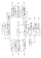
- the maintenance operation described below is executed under the control of the arithmetic unit 100 according to a predetermined program stored in advance in a predetermined recording area in the arithmetic unit 100 or a storage device (not shown).
- the maintenance content determined in advance or instructed by the operator is selected (S1).
- wiping is performed using the wiping unit m1 among the plurality of types of maintenance operations.
- maintenance device basic data relating to the wiping unit m1 for performing wiping is read (S2), and the maintenance unit installation mechanism 14 is moved based on the position coordinate data in the maintenance device basic data.
- the wiping unit m1 is gripped and held by the hand part 14a at the tip from among a plurality of types of maintenance units M (m1, m2, m3), carried to the transport stage 7, and installed on the maintenance unit installation part 13. .
- the maintenance unit M is installed with a certain degree of positioning with respect to the head module 5 (S3, FIG. 11).
- the wiping unit m1 is held on the maintenance unit installation unit 13 by the holding mechanism 13a.
- the transfer stage 7 moves to a predetermined position (installation standby position) so that the maintenance unit installation unit 13 is sufficiently retracted from below the Z stage 4 and is stationary.
- the installation standby position is determined in advance, and the position coordinates are included in the maintenance device basic data read in step S2.
- the transfer stage 7 is moved in the X and Y directions, and the first camera 6 attached to the Z stage 4 is used to select one of the wiping units m1.
- the positioning marker 207 is recognized by image recognition (S4, FIG. 12). This confirmation operation is repeated for the number of positioning markers 207, and the position coordinates of each positioning marker 207 are acquired.
- the attitude of the wiping unit m1 is calculated from each position coordinate.
- FIG. 9 is a flow of posture calculation. First, the position coordinates (X, Y) of the four positioning markers 207 are obtained and stored as marker data 1 to 4 (S20).
- the attitude data of the wiping unit m1 obtained as described above is stored as the current attitude data ( ⁇ m, Mave) of the wiping unit m1 on the maintenance unit installation unit 13 (S5).
- the second camera 12 mounted on the transfer stage 7 is moved to below the head module 5 (S6).
- Any one of the position confirmation markers 52 formed on the lower surface of the head module 5 is recognized by image recognition (S7, FIG. 13). This confirmation operation is repeated for the number of position confirmation markers 52.
- the position coordinates of each confirmed position confirmation marker 52 are set as head marker data, and posture data ( ⁇ h, Hrav) is calculated and stored in the same manner as described above according to the flow of FIG. 9 (S8).
- any of the processes in steps S3 to S5 and the processes in steps S6 to S8 may be performed first. Further, the posture data of the head module 5 may be acquired by executing the processing of steps S6 to S8 as the initial processing of the maintenance operation.
- the head module 5 is not accurately positioned with respect to each head 51. Therefore, in order to properly wipe each head 51 by the wiping unit m1, it is necessary to match the postures of the two.
- the head module 5 and the wiping unit m1 need only be relatively moved in order to match the postures of the two, but here the head module is moved by moving only the wiping unit m1 side in the X, Y and ⁇ directions. It is made to match 5 postures.
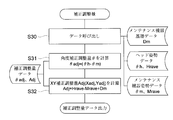
- FIG. 10 is a flowchart for calculating a correction adjustment amount for the movement.
- stored attitude data ( ⁇ m, Mave) of the wiping unit m1 attitude data ( ⁇ h, Hrav) of the head module 5, and maintenance equipment.
- the basic data Dm is called (S30).
- the maintenance device basic data Dm includes information on the contact position relationship between the head module 5 and the wiping unit m1.
- the result is stored (S32).
- the transport stage 7 is moved in the X, Y, and ⁇ directions to finely adjust the position of the maintenance unit m1. (S10). Thereby, the attitude of the wiping unit m1 on the transfer stage 7 matches the attitude of the head module 5 (FIG. 14).
- the transport stage 7 is moved so that the wiping unit m1 is positioned immediately below the head module 5, the Z stage 4 is lowered, and the head module 5 is brought into contact with the wiping unit m1 to perform head maintenance (S11, FIG. 15).
- the ink jet drawing apparatus 1A only needs to provide a space for installing only one type of the plurality of types of maintenance units M (m1, m2, m3) on the transport stage 7. There is no need to make the transfer stage 7 longer and larger, and a mechanism (maintenance unit installation mechanism 14) for installing the maintenance unit M on the transfer stage 7 is not installed on the same surface plate 2 as the transfer stage 7. Therefore, it is possible to suppress the occurrence of positional deviation of the head 51 due to the vibration accompanying the installation operation of the maintenance unit M, and it is possible to perform highly accurate maintenance.
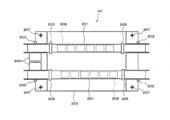
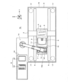
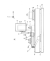
- FIG. 16 is a side view showing a second embodiment of the ink jet drawing apparatus according to the present invention
- FIG. 17 is a plan view thereof. Since the site
- the maintenance unit installation portion and the second camera that the first embodiment has are not formed on the transfer stage 7.
- a plurality of types of maintenance units M are installed in a maintenance unit transport mechanism 18 disposed on the side of the surface plate 2. For this reason, only the drawing table 11 is provided on the transfer stage 7.
- the maintenance unit transport mechanism 18 is composed of a robot arm having an articulated structure similar to the maintenance unit installation mechanism 14 in the first embodiment, and is disposed on the side of the surface plate 2 and is not provided on the surface plate 2. . Therefore, the vibration accompanying the movement does not affect the head module 5 on the surface plate 2, and the installation space for the maintenance unit transport mechanism 18 is not required on the surface plate 2.
- the maintenance unit transport mechanism 18 may be installed on the apparatus base 16 on the side of the surface plate 2 as in the first embodiment.
- a rotary table 18a in which all of a plurality of types of maintenance units M (m1, m2, m3) are installed is provided.
- the rotary table 18a is rotatable in the horizontal ⁇ direction at the tip of the arm, and a plurality of types of maintenance units M (m1, m2, m3) and the head module 5 are placed on the lower surface side at predetermined positions on the upper surface thereof.
- a second camera 12 for recognizing an image from the top to the top is attached and fixed.
- the rotary table 18a can move in a predetermined region including directly below the head module 5 by driving each joint of the maintenance unit transport mechanism 18, and can rotate a plurality of types of maintenance by rotating. Any one of the units M (m 1, m 2, m 3) can be positioned directly below the head module 5, and after positioning, the arm can be lifted to contact each head 51. Therefore, in this embodiment, the maintenance unit transport mechanism 18 in the present invention is constituted by the maintenance unit transport mechanism 18.
- Position information associated with each moving operation of the maintenance unit transport mechanism 18 is detected with high accuracy by an encoder (not shown).
- This positioning operation can also be performed according to FIGS. 8 to 10 in this embodiment.
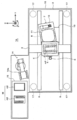
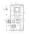
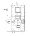
- the drawing table 11 is By inserting the second camera 12 below the retracted head module 5, the position of the head module 5 is confirmed (FIG. 18). At this time, the Z stage 4 moves upward to form a large insertion space below.
- the rotary table 18a rotates, and the flushing tray m3 is transported to the lower side of the first camera 6 provided on the Z stage 4, and the position is confirmed by the first camera 6. (FIG. 19).
- the first camera 6 descends and recognizes the positioning marker 402 on the flushing tray m3.
- the rotary table 18a is rotated so that the flushing tray m3 matches the posture of the head module 5, and the flushing tray m3 is positioned below the head module 5 (FIG. 20).
- the transfer stage 7 having the drawing table 11 is moved to a position (maintenance position) where the drawing table 11 is sufficiently retracted from below the head module 5 by the Y moving mechanism 9 in the Y direction on the surface plate 2. It is possible to move, and a space is secured below the head module 5 in which the rotary table 18a on which the maintenance unit M (m1, m2, m3) and the second camera 12 are installed can be inserted. Since the drawing table 11 is formed so as to protrude from the surface of the transfer stage 7, the moving distance for moving the head module 5 upward can be shortened in order to insert the rotary table 18 a below the head module 5. it can.
- the ink jet drawing apparatus 1B according to the second embodiment can obtain the same effect as that of the first embodiment, and in addition, can arrange a plurality of types of maintenance units M (m1, m2, m3). Since there is no need to provide an arrangement table separately, the installation space for the entire apparatus can be made compact.
- the maintenance unit installation mechanism 14 which is an example of the maintenance unit selection and installation unit described in the first embodiment, may be configured as a multi-joint structure robot arm or the following configuration.
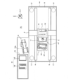
- FIG. 21 is a side view of an ink jet drawing apparatus provided with another embodiment of the maintenance unit selecting / installing means
- FIG. 22 is a plan view thereof.
- a gantry 20 is installed on the end side of the surface plate 2 along the Y direction in the drawing so as to straddle the transport stage 7 and the surface plate 2 along the X direction in the drawing. Therefore, the gantry 20 is not provided on the surface plate 2 but is provided on the apparatus base 16 here.
- a maintenance unit installation mechanism 19 for installing the maintenance unit M on the maintenance unit installation unit 13 on the transfer stage 7 is slidable along the X direction in the drawing and can be moved up and down along the Z direction. Is attached.
- a maintenance unit arrangement table 21 is arranged on the side of the surface plate 2 on the apparatus base 16, and a plurality of types of maintenance units M (m 1, m 2, m 3) are arranged on the upper surface of the gantry 20. Similarly, they are arranged so as to be selectable along the X direction in the figure.
- the maintenance unit installation mechanism 19 has a hand portion 19a for holding and holding the maintenance unit M at the lower end, and a plurality of types of maintenance units M arranged on the maintenance unit arrangement table 21 by the hand portion 19a.
- the maintenance unit selection installation means in the present invention is constituted by the maintenance unit installation mechanism 19 provided in the gantry 20.
Landscapes
- Coating Apparatus (AREA)
- Ink Jet (AREA)
Abstract
Description
前記ヘッドモジュールの直下を含む所定領域を移動可能に構成され、前記液滴吐出ヘッドのメンテナンスを行うためのメンテナンスユニットを前記ヘッドモジュールの直下まで搬送して前記液滴吐出ヘッドに対して位置決めを行うメンテナンスユニット搬送手段と、
前記液滴吐出ヘッドのメンテナンスを行うための複数種類のメンテナンスユニットのうちからいずれか1つのメンテナンスユニットを選択し、該選択されたメンテナンスユニットを前記メンテナンスユニット搬送手段に設置するメンテナンスユニット選択設置手段と、
を備えることを特徴とするインクジェット描画装置である。
前記メンテナンスユニット搬送手段は、前記相対位置計測手段によって計測された計測値に応じて前記メンテナンスユニットの位置を微調整することを特徴とする請求項1記載のインクジェット描画装置である。
前記ヘッドモジュールの直下を含む所定領域を移動可能に構成され、前記液滴吐出ヘッドのメンテナンスを行うためのメンテナンスユニットを前記ヘッドモジュールの直下まで搬送して前記液滴吐出ヘッドに対して位置決めを行うメンテナンスユニット搬送手段を有し、
前記メンテナンスユニット搬送手段は、先端にメンテナンスユニットが設置されると共に該先端が前記ヘッドモジュールの直下を含む所定領域を水平方向及び垂直方向に移動可能なロボットアームにより構成されていることを特徴とするインクジェット描画装置である。
前記メンテナンスユニット搬送手段は、前記相対位置計測手段によって計測された計測値に応じて前記メンテナンスユニットの位置を微調整することを特徴とする請求項9記載のインクジェット描画装置である。
図1は本発明に係るインクジェット描画装置の第1の実施形態を示す側面図、図2はその平面図である。
図16は本発明に係るインクジェット描画装置の第2の実施形態を示す側面図、図17はその平面図である。第1実施形態に係るインクジェット描画装置1Aと同一符号の部位は同一構成の部位であるため詳細な説明は省略する。
第1の実施形態において説明したメンテナンスユニット選択設置手段の一例であるメンテナンスユニット設置機構14は、多関節構造のロボットアームからなる構成とする他、以下の構成とすることもできる。
2 定盤
3 ガントリ
4 Zステージ
5 ヘッドモジュール
51 ヘッド
51a ノズル
52 位置確認用マーカ
6 第1のカメラ
6a レンズ面
7 搬送ステージ
8 θ回転機構
9 Y移動機構
10 X移動機構
11 描画台
12 第2のカメラ
12a レンズ面
13 メンテナンスユニット設置部
13a 保持機構
13b 電極
14、19 メンテナンスユニット設置機構
14a、19a ハンド部
15、21 メンテナンスユニット配置台
16 装置基台
17 除振機構
18 メンテナンスユニット搬送機構
18a 回転テーブル
20 ガントリ
M メンテナンスユニット
m1 ワイピングユニット
m2 サッキングユニット
m3 フラッシングトレイ
Claims (13)
- 液滴を吐出するノズルを有する液滴吐出ヘッドを保持し、水平方向の移動が不可能に構成されたヘッドモジュールと、上面に被記録材を支持し、前記ヘッドモジュールの直下を含む所定領域を水平方向に移動可能に構成された描画台とを有し、前記液滴吐出ヘッドから前記被記録材に向けて液滴を吐出することによって所定の描画を行うインクジェット描画装置であって、
前記ヘッドモジュールの直下を含む所定領域を移動可能に構成され、前記液滴吐出ヘッドのメンテナンスを行うためのメンテナンスユニットを前記ヘッドモジュールの直下まで搬送して前記液滴吐出ヘッドに対して位置決めを行うメンテナンスユニット搬送手段と、
前記液滴吐出ヘッドのメンテナンスを行うための複数種類のメンテナンスユニットのうちからいずれか1つのメンテナンスユニットを選択し、該選択されたメンテナンスユニットを前記メンテナンスユニット搬送手段に設置するメンテナンスユニット選択設置手段と、
を備えることを特徴とするインクジェット描画装置。 - 前記ヘッドモジュールと前記メンテナンスユニット搬送手段によって搬送されるメンテナンスユニットとの相対位置を計測する相対位置計測手段を備え、
前記メンテナンスユニット搬送手段は、前記相対位置計測手段によって計測された計測値に応じて前記メンテナンスユニットの位置を微調整することを特徴とする請求項1記載のインクジェット描画装置。 - 前記メンテナンスユニット選択設置手段は、先端に1つのメンテナンスユニットを保持可能なロボットアームにより構成されていることを特徴とする請求項1又は2記載のインクジェット描画装置。
- 前記メンテナンスユニット選択設置手段は、前記メンテナンスユニット搬送手段を跨ぐように設けられたガントリに沿ってスライド移動可能且つ昇降移動可能に設けられ、下端に1つのメンテナンスユニットを保持可能なハンド部を有していることを特徴とする請求項1又は2記載のインクジェット描画装置。
- 前記複数種類のメンテナンスユニットを上面に配置したメンテナンスユニット配置台を有することを特徴とする請求項1~4のいずれかに記載のインクジェット描画装置。
- 前記ヘッドモジュールと前記描画台は、共通の定盤上に設置されており、前記メンテナンスユニット選択設置手段は、前記定盤上には設置されていないことを特徴とする請求項1~5のいずれかに記載のインクジェット描画装置。
- 前記描画台と前記メンテナンスユニット搬送手段は、前記ヘッドモジュールの直下を含む所定領域を水平方向に移動可能で、且つ、前記描画台の上面に対して垂直方向に沿う方向を軸として回転移動可能に構成された共通のステージ上に設けられていることを特徴とする請求項1~6のいずれかに記載のインクジェット描画装置。
- 前記描画台は、前記メンテナンスユニットによるメンテナンス時に、該メンテナンスユニットと干渉しない位置まで退避し、前記ヘッドモジュールの下方に前記メンテナンスユニットの挿入スペースを確保するように構成されていることを特徴とする請求項1~7のいずれかに記載のインクジェット描画装置。
- 液滴を吐出するノズルを有する液滴吐出ヘッドを保持し、水平方向の移動が不可能に構成されたヘッドモジュールと、上面に被記録材を支持し、前記ヘッドモジュールの直下を含む所定領域を水平方向に移動可能に構成された描画台とを有し、前記液滴吐出ヘッドから前記被記録材に向けて液滴を吐出することによって所定の描画を行うインクジェット描画装置であって、
前記ヘッドモジュールの直下を含む所定領域を移動可能に構成され、前記液滴吐出ヘッドのメンテナンスを行うためのメンテナンスユニットを前記ヘッドモジュールの直下まで搬送して前記液滴吐出ヘッドに対して位置決めを行うメンテナンスユニット搬送手段を有し、
前記メンテナンスユニット搬送手段は、先端にメンテナンスユニットが設置されると共に該先端が前記ヘッドモジュールの直下を含む所定領域を水平方向及び垂直方向に移動可能なロボットアームにより構成されていることを特徴とするインクジェット描画装置。 - 前記ヘッドモジュールと前記メンテナンスユニット搬送手段によって搬送されるメンテナンスユニットとの相対位置を計測する相対位置計測手段を備え、
前記メンテナンスユニット搬送手段は、前記相対位置計測手段によって計測された計測値に応じて前記メンテナンスユニットの位置を微調整することを特徴とする請求項9記載のインクジェット描画装置。 - 前記メンテナンスユニット搬送手段は、先端に複数種類のメンテナンスユニットを設置した回転テーブルを有していることを特徴とする請求項9又は10記載のインクジェット描画装置。
- 前記ヘッドモジュールと前記描画台は、共通の定盤上に設置されており、前記メンテナンスユニット搬送手段は、前記定盤上には設置されていないことを特徴とする請求項9~11のいずれかに記載のインクジェット描画装置。
- 前記描画台は、前記メンテナンスユニットによるメンテナンス時に、該メンテナンスユニットと干渉しない位置まで退避し、前記ヘッドモジュールの下方に前記メンテナンスユニットの挿入スペースを確保するように構成されていることを特徴とする請求項9~12のいずれかに記載のインクジェット描画装置。
Priority Applications (4)
| Application Number | Priority Date | Filing Date | Title |
|---|---|---|---|
| US13/139,834 US8419163B2 (en) | 2008-12-18 | 2009-12-07 | Inkjet drawing apparatus |
| EP09833345.3A EP2359941A4 (en) | 2008-12-18 | 2009-12-07 | INKJET DRAWING APPARATUS |
| JP2010542937A JP5561169B2 (ja) | 2008-12-18 | 2009-12-07 | インクジェット描画装置 |
| US13/846,613 US8733886B2 (en) | 2008-12-18 | 2013-03-18 | Inkjet drawing apparatus |
Applications Claiming Priority (2)
| Application Number | Priority Date | Filing Date | Title |
|---|---|---|---|
| JP2008-322445 | 2008-12-18 | ||
| JP2008322445 | 2008-12-18 |
Related Child Applications (2)
| Application Number | Title | Priority Date | Filing Date |
|---|---|---|---|
| US13/139,834 A-371-Of-International US8419163B2 (en) | 2008-12-18 | 2009-12-07 | Inkjet drawing apparatus |
| US13/846,613 Division US8733886B2 (en) | 2008-12-18 | 2013-03-18 | Inkjet drawing apparatus |
Publications (1)
| Publication Number | Publication Date |
|---|---|
| WO2010071041A1 true WO2010071041A1 (ja) | 2010-06-24 |
Family
ID=42268712
Family Applications (1)
| Application Number | Title | Priority Date | Filing Date |
|---|---|---|---|
| PCT/JP2009/070461 Ceased WO2010071041A1 (ja) | 2008-12-18 | 2009-12-07 | インクジェット描画装置 |
Country Status (4)
| Country | Link |
|---|---|
| US (2) | US8419163B2 (ja) |
| EP (1) | EP2359941A4 (ja) |
| JP (2) | JP5561169B2 (ja) |
| WO (1) | WO2010071041A1 (ja) |
Cited By (6)
| Publication number | Priority date | Publication date | Assignee | Title |
|---|---|---|---|---|
| JP2011215173A (ja) * | 2010-03-31 | 2011-10-27 | Toray Eng Co Ltd | インクジェット塗布装置 |
| EP2559558A1 (en) * | 2011-08-16 | 2013-02-20 | Ricoh Company, Ltd. | Image forming apparatus having carriage mounting recording head for ejecting liquid droplets |
| JP2014508639A (ja) * | 2011-02-08 | 2014-04-10 | リー,グ−ファン | ディスペンシング用のジェットバルブのノズル掃除ブレード |
| JP2017087103A (ja) * | 2015-11-04 | 2017-05-25 | 富士機械製造株式会社 | 印刷装置および部品実装基材の製造装置 |
| US11400718B2 (en) | 2020-03-12 | 2022-08-02 | Ricoh Company, Ltd. | Liquid discharge apparatus |
| WO2022202223A1 (ja) * | 2021-03-23 | 2022-09-29 | 株式会社Screenホールディングス | 印刷装置、印刷方法 |
Families Citing this family (4)
| Publication number | Priority date | Publication date | Assignee | Title |
|---|---|---|---|---|
| JP6642129B2 (ja) * | 2016-03-08 | 2020-02-05 | セイコーエプソン株式会社 | 液体噴射装置 |
| US10864541B2 (en) * | 2018-01-30 | 2020-12-15 | Ford Motor Company | Ultrasonic atomizer with quick-connect mechanism |
| JP7328860B2 (ja) * | 2019-09-30 | 2023-08-17 | セーレン株式会社 | インクジェット記録装置 |
| JP7831062B2 (ja) * | 2022-03-25 | 2026-03-17 | セイコーエプソン株式会社 | 液体吐出装置の制御方法、液体吐出装置 |
Citations (3)
| Publication number | Priority date | Publication date | Assignee | Title |
|---|---|---|---|---|
| JP2005254800A (ja) | 2004-02-13 | 2005-09-22 | Seiko Epson Corp | 液滴吐出装置、並びに電気光学装置の製造方法、電気光学装置および電子機器 |
| JP2005313412A (ja) * | 2004-04-28 | 2005-11-10 | Canon Inc | 吐出口面の清掃方法、液体吐出装置およびプローブ担体の製造装置 |
| JP2008155113A (ja) | 2006-12-22 | 2008-07-10 | Seiko Epson Corp | 液滴吐出装置、及びデバイスの製造方法 |
Family Cites Families (5)
| Publication number | Priority date | Publication date | Assignee | Title |
|---|---|---|---|---|
| JP2004130299A (ja) * | 2002-08-02 | 2004-04-30 | Seiko Epson Corp | 液滴吐出装置、電気光学装置の製造方法、電気光学装置および電子機器 |
| US7275802B2 (en) * | 2005-03-03 | 2007-10-02 | Hewlett-Packard Development Company, L.P. | Cleaner |
| KR100782816B1 (ko) * | 2005-08-19 | 2007-12-06 | 삼성전자주식회사 | 잉크젯 화상형성장치 및 노즐부 메인터넌스 방법 |
| US20080024532A1 (en) * | 2006-07-26 | 2008-01-31 | Si-Kyoung Kim | Methods and apparatus for inkjet printing system maintenance |
| JP2008238143A (ja) * | 2007-03-29 | 2008-10-09 | Seiko Epson Corp | 液滴吐出装置及び液滴吐出ヘッド交換方法 |
-
2009
- 2009-12-07 JP JP2010542937A patent/JP5561169B2/ja active Active
- 2009-12-07 EP EP09833345.3A patent/EP2359941A4/en not_active Withdrawn
- 2009-12-07 US US13/139,834 patent/US8419163B2/en active Active
- 2009-12-07 WO PCT/JP2009/070461 patent/WO2010071041A1/ja not_active Ceased
-
2013
- 2013-03-18 US US13/846,613 patent/US8733886B2/en not_active Expired - Fee Related
-
2014
- 2014-04-07 JP JP2014078750A patent/JP5742997B2/ja active Active
Patent Citations (3)
| Publication number | Priority date | Publication date | Assignee | Title |
|---|---|---|---|---|
| JP2005254800A (ja) | 2004-02-13 | 2005-09-22 | Seiko Epson Corp | 液滴吐出装置、並びに電気光学装置の製造方法、電気光学装置および電子機器 |
| JP2005313412A (ja) * | 2004-04-28 | 2005-11-10 | Canon Inc | 吐出口面の清掃方法、液体吐出装置およびプローブ担体の製造装置 |
| JP2008155113A (ja) | 2006-12-22 | 2008-07-10 | Seiko Epson Corp | 液滴吐出装置、及びデバイスの製造方法 |
Non-Patent Citations (1)
| Title |
|---|
| See also references of EP2359941A4 |
Cited By (11)
| Publication number | Priority date | Publication date | Assignee | Title |
|---|---|---|---|---|
| JP2011215173A (ja) * | 2010-03-31 | 2011-10-27 | Toray Eng Co Ltd | インクジェット塗布装置 |
| JP2014508639A (ja) * | 2011-02-08 | 2014-04-10 | リー,グ−ファン | ディスペンシング用のジェットバルブのノズル掃除ブレード |
| EP2559558A1 (en) * | 2011-08-16 | 2013-02-20 | Ricoh Company, Ltd. | Image forming apparatus having carriage mounting recording head for ejecting liquid droplets |
| JP2013039723A (ja) * | 2011-08-16 | 2013-02-28 | Ricoh Co Ltd | 画像形成装置 |
| CN102950898A (zh) * | 2011-08-16 | 2013-03-06 | 株式会社理光 | 图像形成装置 |
| US8622511B2 (en) | 2011-08-16 | 2014-01-07 | Ricoh Company, Ltd. | Image forming apparatus having carriage mounting recording head for ejecting liquid droplets |
| JP2017087103A (ja) * | 2015-11-04 | 2017-05-25 | 富士機械製造株式会社 | 印刷装置および部品実装基材の製造装置 |
| US11400718B2 (en) | 2020-03-12 | 2022-08-02 | Ricoh Company, Ltd. | Liquid discharge apparatus |
| WO2022202223A1 (ja) * | 2021-03-23 | 2022-09-29 | 株式会社Screenホールディングス | 印刷装置、印刷方法 |
| JP7614900B2 (ja) | 2021-03-23 | 2025-01-16 | 株式会社Screenホールディングス | 印刷装置、印刷方法 |
| US12434477B2 (en) | 2021-03-23 | 2025-10-07 | SCREEN Holdings Co., Ltd. | Printer and printing method |
Also Published As
| Publication number | Publication date |
|---|---|
| US20110249059A1 (en) | 2011-10-13 |
| JP2014176845A (ja) | 2014-09-25 |
| JP5742997B2 (ja) | 2015-07-01 |
| US20130215190A1 (en) | 2013-08-22 |
| JP5561169B2 (ja) | 2014-07-30 |
| EP2359941A1 (en) | 2011-08-24 |
| US8733886B2 (en) | 2014-05-27 |
| JPWO2010071041A1 (ja) | 2012-05-24 |
| EP2359941A4 (en) | 2016-10-26 |
| US8419163B2 (en) | 2013-04-16 |
Similar Documents
| Publication | Publication Date | Title |
|---|---|---|
| JP5742997B2 (ja) | インクジェット描画装置 | |
| CN101484248B (zh) | 缺陷修复装置和缺陷修复方法 | |
| CN100363115C (zh) | 小滴喷射装置和电光学装置及其制造方法和电子器件 | |
| JP5556661B2 (ja) | インクジェット描画装置 | |
| WO2007129634A1 (ja) | 液滴塗布装置 | |
| WO2007123077A1 (ja) | 液滴塗布装置 | |
| WO2007132705A1 (ja) | 液滴吐出描画装置 | |
| JP6433263B2 (ja) | 液体吐出ヘッドの製造方法 | |
| WO2007123076A1 (ja) | 液滴塗布装置 | |
| JP2011240248A (ja) | インクジェットヘッド用ハウジング | |
| KR101986892B1 (ko) | 기능액 토출 장치 및 기능액 토출 위치 보정 방법 | |
| JP2009279531A (ja) | 描画検査装置および描画検査方法 | |
| JP2004172318A (ja) | ワークテーブル、ワーク搬送装置、液滴吐出装置、ワーク受け渡し方法、電気光学装置、電気光学装置の製造方法および電子機器 | |
| JP4541321B2 (ja) | 液滴塗布装置、液滴塗布方法、プログラム及びコンピュータ読み取り可能な記録媒体 | |
| JP4739426B2 (ja) | インクジェットヘッド取付け位置調整方法、及びインクジェット装置のヘッド位置制御方法 | |
| JP4036016B2 (ja) | インクジェット装置 | |
| JP4534546B2 (ja) | 液滴吐出装置、位置調整方法、電気光学装置の製造方法 | |
| JP2004172317A (ja) | ワーク位置決め装置、ワーク位置決め方法、液滴吐出装置、電気光学装置、電気光学装置の製造方法および電子機器 | |
| JP2019000780A (ja) | インクジェット塗布装置 | |
| JP2004243186A (ja) | 長尺体配設構造、液滴吐出装置、電気光学装置、電気光学装置の製造方法および電子機器 | |
| JP2005324115A (ja) | 塗布装置 | |
| JP2003270427A (ja) | 製膜装置、デバイス製造装置およびデバイス製造方法並びにデバイス | |
| JP2007090173A (ja) | 液滴塗布装置 | |
| JP2010075892A (ja) | 液体噴射装置、描画方法 | |
| JP2003265998A (ja) | 製膜装置、デバイス製造装置およびデバイスの製造方法並びにデバイス |
Legal Events
| Date | Code | Title | Description |
|---|---|---|---|
| 121 | Ep: the epo has been informed by wipo that ep was designated in this application |
Ref document number: 09833345 Country of ref document: EP Kind code of ref document: A1 |
|
| ENP | Entry into the national phase |
Ref document number: 2010542937 Country of ref document: JP Kind code of ref document: A |
|
| WWE | Wipo information: entry into national phase |
Ref document number: 2009833345 Country of ref document: EP |
|
| WWE | Wipo information: entry into national phase |
Ref document number: 13139834 Country of ref document: US |
|
| NENP | Non-entry into the national phase |
Ref country code: DE |