WO2010071205A1 - 排ガス浄化用触媒 - Google Patents
排ガス浄化用触媒 Download PDFInfo
- Publication number
- WO2010071205A1 WO2010071205A1 PCT/JP2009/071172 JP2009071172W WO2010071205A1 WO 2010071205 A1 WO2010071205 A1 WO 2010071205A1 JP 2009071172 W JP2009071172 W JP 2009071172W WO 2010071205 A1 WO2010071205 A1 WO 2010071205A1
- Authority
- WO
- WIPO (PCT)
- Prior art keywords
- catalyst
- exhaust gas
- earth metal
- alkaline earth
- slurry
- Prior art date
- Legal status (The legal status is an assumption and is not a legal conclusion. Google has not performed a legal analysis and makes no representation as to the accuracy of the status listed.)
- Ceased
Links
Images
Classifications
-
- F—MECHANICAL ENGINEERING; LIGHTING; HEATING; WEAPONS; BLASTING
- F01—MACHINES OR ENGINES IN GENERAL; ENGINE PLANTS IN GENERAL; STEAM ENGINES
- F01N—GAS-FLOW SILENCERS OR EXHAUST APPARATUS FOR MACHINES OR ENGINES IN GENERAL; GAS-FLOW SILENCERS OR EXHAUST APPARATUS FOR INTERNAL-COMBUSTION ENGINES
- F01N3/00—Exhaust or silencing apparatus having means for purifying, rendering innocuous, or otherwise treating exhaust
- F01N3/08—Exhaust or silencing apparatus having means for purifying, rendering innocuous, or otherwise treating exhaust for rendering innocuous
- F01N3/10—Exhaust or silencing apparatus having means for purifying, rendering innocuous, or otherwise treating exhaust for rendering innocuous by thermal or catalytic conversion of noxious components of exhaust
-
- B—PERFORMING OPERATIONS; TRANSPORTING
- B01—PHYSICAL OR CHEMICAL PROCESSES OR APPARATUS IN GENERAL
- B01D—SEPARATION
- B01D53/00—Separation of gases or vapours; Recovering vapours of volatile solvents from gases; Chemical or biological purification of waste gases, e.g. engine exhaust gases, smoke, fumes, flue gases, aerosols
- B01D53/34—Chemical or biological purification of waste gases
- B01D53/92—Chemical or biological purification of waste gases of engine exhaust gases
- B01D53/94—Chemical or biological purification of waste gases of engine exhaust gases by catalytic processes
- B01D53/9445—Simultaneously removing carbon monoxide, hydrocarbons or nitrogen oxides making use of three-way catalysts [TWC] or four-way-catalysts [FWC]
- B01D53/945—Simultaneously removing carbon monoxide, hydrocarbons or nitrogen oxides making use of three-way catalysts [TWC] or four-way-catalysts [FWC] characterised by a specific catalyst
-
- B—PERFORMING OPERATIONS; TRANSPORTING
- B01—PHYSICAL OR CHEMICAL PROCESSES OR APPARATUS IN GENERAL
- B01J—CHEMICAL OR PHYSICAL PROCESSES, e.g. CATALYSIS OR COLLOID CHEMISTRY; THEIR RELEVANT APPARATUS
- B01J23/00—Catalysts comprising metals or metal oxides or hydroxides, not provided for in group B01J21/00
- B01J23/02—Catalysts comprising metals or metal oxides or hydroxides, not provided for in group B01J21/00 of the alkali- or alkaline earth metals or beryllium
-
- B—PERFORMING OPERATIONS; TRANSPORTING
- B01—PHYSICAL OR CHEMICAL PROCESSES OR APPARATUS IN GENERAL
- B01J—CHEMICAL OR PHYSICAL PROCESSES, e.g. CATALYSIS OR COLLOID CHEMISTRY; THEIR RELEVANT APPARATUS
- B01J23/00—Catalysts comprising metals or metal oxides or hydroxides, not provided for in group B01J21/00
- B01J23/38—Catalysts comprising metals or metal oxides or hydroxides, not provided for in group B01J21/00 of noble metals
- B01J23/54—Catalysts comprising metals or metal oxides or hydroxides, not provided for in group B01J21/00 of noble metals combined with metals, oxides or hydroxides provided for in groups B01J23/02 - B01J23/36
- B01J23/56—Platinum group metals
- B01J23/58—Platinum group metals with alkali- or alkaline earth metals
-
- B—PERFORMING OPERATIONS; TRANSPORTING
- B01—PHYSICAL OR CHEMICAL PROCESSES OR APPARATUS IN GENERAL
- B01J—CHEMICAL OR PHYSICAL PROCESSES, e.g. CATALYSIS OR COLLOID CHEMISTRY; THEIR RELEVANT APPARATUS
- B01J23/00—Catalysts comprising metals or metal oxides or hydroxides, not provided for in group B01J21/00
- B01J23/38—Catalysts comprising metals or metal oxides or hydroxides, not provided for in group B01J21/00 of noble metals
- B01J23/54—Catalysts comprising metals or metal oxides or hydroxides, not provided for in group B01J21/00 of noble metals combined with metals, oxides or hydroxides provided for in groups B01J23/02 - B01J23/36
- B01J23/56—Platinum group metals
- B01J23/63—Platinum group metals with rare earths or actinides
-
- B—PERFORMING OPERATIONS; TRANSPORTING
- B01—PHYSICAL OR CHEMICAL PROCESSES OR APPARATUS IN GENERAL
- B01J—CHEMICAL OR PHYSICAL PROCESSES, e.g. CATALYSIS OR COLLOID CHEMISTRY; THEIR RELEVANT APPARATUS
- B01J37/00—Processes, in general, for preparing catalysts; Processes, in general, for activation of catalysts
- B01J37/02—Impregnation, coating or precipitation
- B01J37/0234—Impregnation and coating simultaneously
-
- B—PERFORMING OPERATIONS; TRANSPORTING
- B01—PHYSICAL OR CHEMICAL PROCESSES OR APPARATUS IN GENERAL
- B01J—CHEMICAL OR PHYSICAL PROCESSES, e.g. CATALYSIS OR COLLOID CHEMISTRY; THEIR RELEVANT APPARATUS
- B01J37/00—Processes, in general, for preparing catalysts; Processes, in general, for activation of catalysts
- B01J37/02—Impregnation, coating or precipitation
- B01J37/024—Multiple impregnation or coating
- B01J37/0244—Coatings comprising several layers
-
- B—PERFORMING OPERATIONS; TRANSPORTING
- B01—PHYSICAL OR CHEMICAL PROCESSES OR APPARATUS IN GENERAL
- B01J—CHEMICAL OR PHYSICAL PROCESSES, e.g. CATALYSIS OR COLLOID CHEMISTRY; THEIR RELEVANT APPARATUS
- B01J37/00—Processes, in general, for preparing catalysts; Processes, in general, for activation of catalysts
- B01J37/02—Impregnation, coating or precipitation
- B01J37/03—Precipitation; Co-precipitation
- B01J37/031—Precipitation
-
- F—MECHANICAL ENGINEERING; LIGHTING; HEATING; WEAPONS; BLASTING
- F01—MACHINES OR ENGINES IN GENERAL; ENGINE PLANTS IN GENERAL; STEAM ENGINES
- F01N—GAS-FLOW SILENCERS OR EXHAUST APPARATUS FOR MACHINES OR ENGINES IN GENERAL; GAS-FLOW SILENCERS OR EXHAUST APPARATUS FOR INTERNAL-COMBUSTION ENGINES
- F01N3/00—Exhaust or silencing apparatus having means for purifying, rendering innocuous, or otherwise treating exhaust
- F01N3/08—Exhaust or silencing apparatus having means for purifying, rendering innocuous, or otherwise treating exhaust for rendering innocuous
- F01N3/0807—Exhaust or silencing apparatus having means for purifying, rendering innocuous, or otherwise treating exhaust for rendering innocuous by using absorbents or adsorbents
- F01N3/0814—Exhaust or silencing apparatus having means for purifying, rendering innocuous, or otherwise treating exhaust for rendering innocuous by using absorbents or adsorbents combined with catalytic converters, e.g. NOx absorption/storage reduction catalysts
-
- F—MECHANICAL ENGINEERING; LIGHTING; HEATING; WEAPONS; BLASTING
- F01—MACHINES OR ENGINES IN GENERAL; ENGINE PLANTS IN GENERAL; STEAM ENGINES
- F01N—GAS-FLOW SILENCERS OR EXHAUST APPARATUS FOR MACHINES OR ENGINES IN GENERAL; GAS-FLOW SILENCERS OR EXHAUST APPARATUS FOR INTERNAL-COMBUSTION ENGINES
- F01N3/00—Exhaust or silencing apparatus having means for purifying, rendering innocuous, or otherwise treating exhaust
- F01N3/08—Exhaust or silencing apparatus having means for purifying, rendering innocuous, or otherwise treating exhaust for rendering innocuous
- F01N3/0807—Exhaust or silencing apparatus having means for purifying, rendering innocuous, or otherwise treating exhaust for rendering innocuous by using absorbents or adsorbents
- F01N3/0828—Exhaust or silencing apparatus having means for purifying, rendering innocuous, or otherwise treating exhaust for rendering innocuous by using absorbents or adsorbents characterised by the absorbed or adsorbed substances
- F01N3/0864—Oxygen
-
- B—PERFORMING OPERATIONS; TRANSPORTING
- B01—PHYSICAL OR CHEMICAL PROCESSES OR APPARATUS IN GENERAL
- B01D—SEPARATION
- B01D2255/00—Catalysts
- B01D2255/10—Noble metals or compounds thereof
- B01D2255/102—Platinum group metals
- B01D2255/1021—Platinum
-
- B—PERFORMING OPERATIONS; TRANSPORTING
- B01—PHYSICAL OR CHEMICAL PROCESSES OR APPARATUS IN GENERAL
- B01D—SEPARATION
- B01D2255/00—Catalysts
- B01D2255/10—Noble metals or compounds thereof
- B01D2255/102—Platinum group metals
- B01D2255/1023—Palladium
-
- B—PERFORMING OPERATIONS; TRANSPORTING
- B01—PHYSICAL OR CHEMICAL PROCESSES OR APPARATUS IN GENERAL
- B01D—SEPARATION
- B01D2255/00—Catalysts
- B01D2255/10—Noble metals or compounds thereof
- B01D2255/102—Platinum group metals
- B01D2255/1025—Rhodium
-
- B—PERFORMING OPERATIONS; TRANSPORTING
- B01—PHYSICAL OR CHEMICAL PROCESSES OR APPARATUS IN GENERAL
- B01D—SEPARATION
- B01D2255/00—Catalysts
- B01D2255/20—Metals or compounds thereof
- B01D2255/204—Alkaline earth metals
- B01D2255/2042—Barium
-
- B—PERFORMING OPERATIONS; TRANSPORTING
- B01—PHYSICAL OR CHEMICAL PROCESSES OR APPARATUS IN GENERAL
- B01D—SEPARATION
- B01D2255/00—Catalysts
- B01D2255/40—Mixed oxides
- B01D2255/407—Zr-Ce mixed oxides
-
- B—PERFORMING OPERATIONS; TRANSPORTING
- B01—PHYSICAL OR CHEMICAL PROCESSES OR APPARATUS IN GENERAL
- B01D—SEPARATION
- B01D2255/00—Catalysts
- B01D2255/90—Physical characteristics of catalysts
- B01D2255/902—Multilayered catalyst
- B01D2255/9022—Two layers
-
- B—PERFORMING OPERATIONS; TRANSPORTING
- B01—PHYSICAL OR CHEMICAL PROCESSES OR APPARATUS IN GENERAL
- B01J—CHEMICAL OR PHYSICAL PROCESSES, e.g. CATALYSIS OR COLLOID CHEMISTRY; THEIR RELEVANT APPARATUS
- B01J2235/00—Indexing scheme associated with group B01J35/00, related to the analysis techniques used to determine the catalysts form or properties
-
- F—MECHANICAL ENGINEERING; LIGHTING; HEATING; WEAPONS; BLASTING
- F01—MACHINES OR ENGINES IN GENERAL; ENGINE PLANTS IN GENERAL; STEAM ENGINES
- F01N—GAS-FLOW SILENCERS OR EXHAUST APPARATUS FOR MACHINES OR ENGINES IN GENERAL; GAS-FLOW SILENCERS OR EXHAUST APPARATUS FOR INTERNAL-COMBUSTION ENGINES
- F01N2370/00—Selection of materials for exhaust purification
- F01N2370/02—Selection of materials for exhaust purification used in catalytic reactors
-
- F—MECHANICAL ENGINEERING; LIGHTING; HEATING; WEAPONS; BLASTING
- F01—MACHINES OR ENGINES IN GENERAL; ENGINE PLANTS IN GENERAL; STEAM ENGINES
- F01N—GAS-FLOW SILENCERS OR EXHAUST APPARATUS FOR MACHINES OR ENGINES IN GENERAL; GAS-FLOW SILENCERS OR EXHAUST APPARATUS FOR INTERNAL-COMBUSTION ENGINES
- F01N2510/00—Surface coverings
- F01N2510/06—Surface coverings for exhaust purification, e.g. catalytic reaction
-
- F—MECHANICAL ENGINEERING; LIGHTING; HEATING; WEAPONS; BLASTING
- F01—MACHINES OR ENGINES IN GENERAL; ENGINE PLANTS IN GENERAL; STEAM ENGINES
- F01N—GAS-FLOW SILENCERS OR EXHAUST APPARATUS FOR MACHINES OR ENGINES IN GENERAL; GAS-FLOW SILENCERS OR EXHAUST APPARATUS FOR INTERNAL-COMBUSTION ENGINES
- F01N2510/00—Surface coverings
- F01N2510/06—Surface coverings for exhaust purification, e.g. catalytic reaction
- F01N2510/068—Surface coverings for exhaust purification, e.g. catalytic reaction characterised by the distribution of the catalytic coatings
- F01N2510/0684—Surface coverings for exhaust purification, e.g. catalytic reaction characterised by the distribution of the catalytic coatings having more than one coating layer, e.g. multi-layered coatings
-
- F—MECHANICAL ENGINEERING; LIGHTING; HEATING; WEAPONS; BLASTING
- F01—MACHINES OR ENGINES IN GENERAL; ENGINE PLANTS IN GENERAL; STEAM ENGINES
- F01N—GAS-FLOW SILENCERS OR EXHAUST APPARATUS FOR MACHINES OR ENGINES IN GENERAL; GAS-FLOW SILENCERS OR EXHAUST APPARATUS FOR INTERNAL-COMBUSTION ENGINES
- F01N2570/00—Exhaust treating apparatus eliminating, absorbing or adsorbing specific elements or compounds
- F01N2570/14—Nitrogen oxides
-
- Y—GENERAL TAGGING OF NEW TECHNOLOGICAL DEVELOPMENTS; GENERAL TAGGING OF CROSS-SECTIONAL TECHNOLOGIES SPANNING OVER SEVERAL SECTIONS OF THE IPC; TECHNICAL SUBJECTS COVERED BY FORMER USPC CROSS-REFERENCE ART COLLECTIONS [XRACs] AND DIGESTS
- Y02—TECHNOLOGIES OR APPLICATIONS FOR MITIGATION OR ADAPTATION AGAINST CLIMATE CHANGE
- Y02T—CLIMATE CHANGE MITIGATION TECHNOLOGIES RELATED TO TRANSPORTATION
- Y02T10/00—Road transport of goods or passengers
- Y02T10/10—Internal combustion engine [ICE] based vehicles
- Y02T10/12—Improving ICE efficiencies
Definitions
- the present invention relates to an exhaust gas purifying catalyst.
- Many exhaust gas purifying catalysts contain palladium and / or platinum as catalytic metals.
- Palladium and / or platinum has a role of promoting the reduction reaction of the oxidation reactions and NO x of HC and CO.
- An object of the present invention is to provide a technique capable of achieving excellent exhaust gas purification performance.
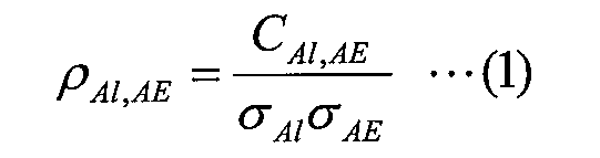
- the substrate includes a substrate, palladium and / or platinum formed on the substrate and doped with an alkaline earth metal element, and is given by the following formula (1):
- an exhaust gas purifying catalyst comprising a first catalyst layer having a correlation coefficient ⁇ Al, AE of 0.75 or more.
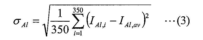
- C Al, AE , ⁇ Al, and ⁇ AE are represented by the following formulas (2), (3), and (4), respectively.
- i is a natural number of 1 to 350
- I Al, i is i among 350 points obtained by equally dividing the first catalyst layer in the thickness direction by 350.
- it is the characteristic X-ray intensity of aluminum measured using an electron beam microanalyzer
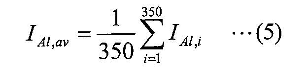
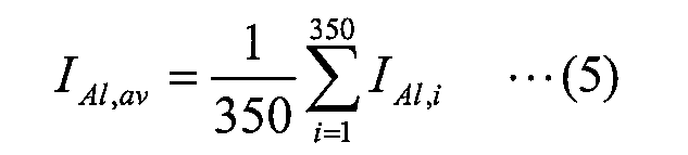
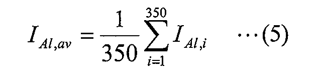
- I Al, av is an arithmetic mean value of I Al, i given by the following equation (5).
- I AE, i is the characteristic X-ray intensity of the alkaline earth metal element measured using the electron beam microanalyzer at the i-th point
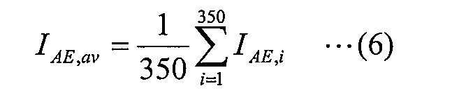
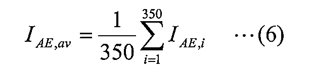
- I AE, av is the following formula (6) Is the arithmetic mean value of I AE, i given by
- a catalyst layer obtained by applying a slurry containing a substrate, palladium and / or platinum, and alumina doped with an alkaline earth metal element on the substrate; An exhaust gas purifying catalyst is provided.
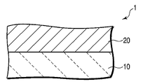
- FIG. 1 is a cross-sectional view schematically showing an exhaust gas purifying catalyst according to a first embodiment of the present invention.
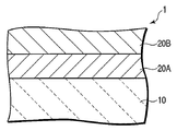
- Sectional drawing which shows schematically the catalyst for exhaust gas purification which concerns on the 2nd aspect of this invention.
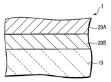
- Sectional drawing which shows schematically the catalyst for exhaust gas purification which concerns on the 3rd aspect of this invention.
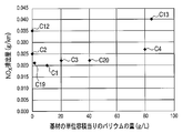
- the graph which shows an example of the relationship between the quantity of barium per unit volume of a base material, and NOx discharge
- composite oxide here means that a plurality of oxides are not simply physically mixed but a plurality of oxides form a solid solution.
- alkaline earth metal includes beryllium and magnesium.
- FIG. 1 is a cross-sectional view schematically showing an exhaust gas purifying catalyst according to the first embodiment of the present invention.
- the exhaust gas-purifying catalyst 1 includes a base material 10 and a catalyst layer 20 formed on the base material 10.
- the base material 10 for example, a monolith honeycomb type base material is used.
- the substrate is made of a ceramic such as cordierite.
- the catalyst layer 20 contains palladium and / or platinum and alumina doped with an alkaline earth metal element. Palladium and / or platinum are typically supported on alumina doped with an alkaline earth metal element. The palladium and / or platinum, is responsible for catalyzing the reduction reaction of the oxidation reactions and NO x of HC and CO.
- Alumina doped with an alkaline earth metal element has a structure in which the alkaline earth metal element is located inside each alumina particle.
- These alkaline earth metal elements may substitute a part of atoms constituting the crystal lattice of alumina, or may be located in a space between these atoms.
- part of the alkaline earth metal element replaces part of the atoms constituting the crystal lattice of alumina, and the other part of the alkaline earth metal element is located in the gap between these atoms. It may be.
- Alkaline earth metal element doped in alumina plays a role of suppressing HC poisoning of palladium and / or platinum.
- the alkaline earth metal element for example, barium, calcium, strontium, or a combination of two or more thereof is used.
- the contact between palladium supported on alumina and / or platinum and the alkaline earth metal element is relatively low. Not likely to occur. That is, a part of the alkaline earth metal element is in contact with the palladium and / or platinum, but the other part of the alkaline earth metal element is not in contact with the palladium and / or platinum. And the alkaline-earth metal element which does not contact palladium and / or platinum does not contribute to suppression of HC poisoning of palladium and / or platinum. Therefore, when there are many such alkaline earth metal elements, it may be difficult to improve the exhaust gas purification performance of the catalyst.
- the alkaline earth metal element when alumina doped with an alkaline earth metal element is used, the alkaline earth metal element can be distributed with high uniformity in the structure of the alumina.
- the alkaline earth metal element doped in the alumina and the palladium and / or platinum supported on the alumina exist close to each other. That is, in this case, contact between the alkaline earth metal element and palladium and / or platinum is more likely to occur than when a mixture of alumina and a salt of the alkaline earth metal element is used. Therefore, in this case, it is possible to more efficiently suppress palladium and / or platinum HC poisoning. Therefore, by adopting such a configuration, particularly excellent exhaust gas purification performance can be achieved.
- C Al, AE is the covariance between the intensity I Al, i and the intensity I AE, i
- ⁇ Al is the standard deviation of the intensity I Al
- ⁇ AE is the intensity I AE
- I AE is the standard deviation of i .
- the covariance C Al, AE and the standard deviations ⁇ Al and ⁇ AE are given by the following equations (2) to (4), respectively.
- I Al, av is an arithmetic mean value of the intensity I Al, i given by the following equation (5)
- I AE, av is the intensity I AE, av given by the following equation (6) . It is an arithmetic mean value of i .
- the correlation coefficient ⁇ Al, AE represented by the equation (1) is an index representing the correlation between the aluminum distribution and the alkaline earth metal element distribution in the catalyst layer 20. That is, when the alkaline earth metal element is relatively uniformly distributed in the catalyst layer 20, the correlation coefficient ⁇ Al, AE becomes a large positive value of 1 or less. On the other hand, when the alkaline earth metal element is relatively unevenly distributed in the catalyst layer 20, the correlation coefficient ⁇ Al, AE becomes a small value close to zero.
- the correlation coefficient ⁇ Al, AE when used, the uniformity of the distribution of the alkaline earth metal element in the catalyst layer 20 can be evaluated.
- the correlation coefficient ⁇ Al, AE of the catalyst layer 20 is 0.75 or more, and typically 0.79 or more.
- the catalyst layer 20 may further contain an oxygen storage material.
- an oxygen storage material for example, cerium oxide, zirconium oxide, or a composite oxide thereof is used.
- a rare earth oxide such as praseodymium oxide, lanthanum oxide, and yttrium oxide, a transition metal oxide such as iron oxide and manganese oxide, or a composite oxide thereof may be used as the oxygen storage material.
- a composite oxide of cerium oxide and zirconium oxide a composite oxide of cerium oxide, zirconium oxide, and lanthanum oxide, or cerium oxide and zirconium oxide
- a composite oxide of lanthanum oxide and yttrium oxide is used.
- the catalyst layer 20 may further contain a rare earth element.
- Rare earth element without reducing the HC purification performance of the exhaust gas purifying catalyst 1 has a function to improve the the NO x purification performance.
- this rare earth element for example, neodymium, lanthanum, praseodymium, or yttrium can be used.
- the catalyst layer 20 may further contain zeolite.
- Zeolite has a high specific surface area and is excellent in the ability to adsorb HC in exhaust gas. Therefore, the HC purification performance of the exhaust gas purification catalyst 1 can be further improved by containing zeolite.
- the catalyst layer 20 may further contain a binder.
- the binder plays a role of enhancing the durability of the catalyst by further strengthening the bond between the plurality of particles constituting the catalyst layer 20.
- alumina sol, titania sol, or silica sol is used as the binder.
- the content of the alkaline earth metal element per unit volume of the substrate 10 is, for example, in the range of 0.1 g / L to 80 g / L, and typically 1 g / L to 40 g / L. Within the range of L. When this content is less than 0.1 g / L, suppression of HC poisoning of palladium and / or platinum by an alkaline earth metal element may be insufficient. If the content is more than 80 g / L, the heat resistance of the catalyst layer 20 may be reduced, and the aggregation of palladium and / or platinum may be likely to occur.
- the alkaline earth metal element doping amount is, for example, in the range of 0.1% by mass to 20% by mass based on the mass of the alumina doped with the alkaline earth metal element. Is in the range of 1 to 10% by mass.
- the doping amount is less than 0.1% by mass, the suppression of HC poisoning of palladium and / or platinum by an alkaline earth metal element may be insufficient.
- the doping amount is more than 20% by mass, the heat resistance of alumina doped with an alkaline earth metal element is lowered, and there is a possibility that aggregation of palladium and / or platinum is likely to occur.
- the mass ratio of the alkaline earth metal element content to the palladium and / or platinum content in the catalyst layer 20 is, for example, in the range of 0.1 to 80, typically Within the range of 0.5 to 40. When this mass ratio is less than 0.1, suppression of HC poisoning of palladium and / or platinum by an alkaline earth metal element may be insufficient. When this mass ratio is larger than 80, there is a possibility that aggregation of palladium and / or platinum is likely to occur.
- alumina doped with an alkaline earth metal element is prepared as follows. That is, first, a mixed aqueous solution containing aluminum nitrate, an alkaline earth metal element carbonate and citric acid is prepared. Next, hydrazine is added to the mixed aqueous solution. Thereafter, the reaction system is heated and stirred to obtain a precipitate. The precipitate is filtered off and the resulting filter cake is dried. Next, the obtained solid is fired. In this way, alumina doped with an alkaline earth metal element is obtained.
- the catalyst layer 20 of the exhaust gas purifying catalyst 1 is obtained, for example, by applying a slurry containing palladium and / or platinum and alumina doped with an alkaline earth metal element on the substrate 10.
- a palladium salt such as palladium nitrate or a palladium complex is used as the material of the slurry.
- platinum is used as the constituent component of the catalyst layer 20, for example, a platinum complex such as dinitrodiamine platinum nitric acid or a platinum salt is used as the material of the slurry.
- the exhaust gas-purifying catalyst 1 may further include another catalyst layer on the catalyst layer 20 or between the catalyst layer 20 and the substrate 10.
- the catalyst layer 20 and other catalyst layers are different from each other in the type and content of the catalyst metal. Thereby, the exhaust gas purification performance of the exhaust gas purification catalyst 1 can be optimized.
- FIG. 2 is a cross-sectional view schematically showing an exhaust gas purifying catalyst according to the second embodiment of the present invention.
- the exhaust gas-purifying catalyst 1 includes a base material 10, a first catalyst layer 20A formed on the base material 10, and a second catalyst layer 20B formed on the first catalyst layer 20A.
- the first catalyst layer 20A has the same configuration as the catalyst layer 20 described with reference to FIG. That is, the exhaust gas-purifying catalyst 1 has the same configuration as that of the exhaust gas-purifying catalyst described with reference to FIG. 1 except that it further includes the second catalyst layer 20B.
- the second catalyst layer 20B contains rhodium. Rhodium plays a role of catalyzing the oxidation reaction of HC and CO and the reduction reaction of NO x .
- the second catalyst layer 20B may further contain alumina.
- the second catalyst layer 20B typically does not include alumina doped with an alkaline earth metal element.
- the second catalyst layer 20B may include alumina doped with an alkaline earth metal element.
- the content of the alkaline earth metal element per unit volume of the base material 10 in the second catalyst layer 20B is the alkaline earth per unit volume of the base material 10 in the first catalyst layer 20A. The content is lower than the content of similar metal elements.
- the second catalyst layer 20B may further contain an oxygen storage material.
- an oxygen storage material the same material as described for the catalyst layer 20 of the exhaust gas-purifying catalyst 1 described with reference to FIG. 1 can be used.
- the oxygen storage material a composite oxide of cerium oxide and zirconium oxide is typically used.
- the second catalyst layer 20B may further contain a rare earth element, zeolite, or binder. As these elements or materials, the same elements as described for the catalyst layer 20 can be used.
- FIG. 3 is a cross-sectional view schematically showing an exhaust gas purifying catalyst according to the third aspect of the present invention.
- the exhaust gas-purifying catalyst 1 includes a base material 10, a second catalyst layer 20B formed on the base material 10, and a first catalyst layer 20A formed on the second catalyst layer 20B. That is, the exhaust gas-purifying catalyst 1 has the same configuration as the exhaust gas-purifying catalyst described with reference to FIG. 2 except that the stacking order of the first catalyst layer 20A and the second catalyst layer 20B is reversed. have.
- the uniformity of the alkaline earth metal element distribution in each of the first catalyst layer 20A and the second catalyst layer 20B is, for example, as follows: Can be evaluated.
- the catalyst layers 20A and 20B are arranged in the configuration shown in FIG. 2 will be described.
- the correlation coefficient ⁇ Al, AE in the first catalyst layer 20A is 0.75 or more, and typically 0.79 or more. . That is, in the exhaust gas-purifying catalyst 1, the alkaline earth metal element is relatively uniformly distributed at least in the first catalyst layer 20A.
- Alumina doped with an alkaline earth metal element was prepared as follows. That is, first, a mixed aqueous solution containing aluminum nitrate, an alkaline earth metal element carbonate and citric acid was prepared. Next, hydrazine was added to the mixed aqueous solution. Thereafter, the reaction system was stirred at 70 ° C. for 24 hours to obtain a precipitate. The precipitate was filtered off and the resulting filter cake was dried. The resulting solid was then calcined at 900 ° C. for 5 hours. In this way, alumina doped with an alkaline earth metal element was obtained.
- the doping amount of the alkaline earth metal element was appropriately adjusted by changing the mass ratio of aluminum nitrate and carbonate of the alkaline earth metal element.
- Example 1 Production of catalyst C1> An alumina doped with 10% by mass of barium was prepared. Hereinafter, this is referred to as “Ba alumina BA1”.
- CZ oxide a composite oxide of cerium oxide and zirconium oxide.
- the molar ratio of the cerium element to the zirconium element was 7/3.
- this composite oxide is referred to as “CZ oxide”.
- slurry S1 100 g of Ba alumina BA1, 100 g of CZ oxide, and an aqueous palladium nitrate solution containing 1 g of palladium were mixed to prepare a slurry.
- this slurry is referred to as “slurry S1”.
- the slurry S1 was applied on the base material. Next, this was dried at 250 ° C. for 1 hour and then calcined at 500 ° C. for 1 hour.
- catalyst C1 an exhaust gas purification catalyst
- Example 2 Production of catalyst C2> An alumina doped with 0.1% by mass of barium was prepared. Hereinafter, this is referred to as “Ba alumina BA2”.
- a slurry was prepared in the same manner as the slurry S1, except that Ba alumina BA2 was used instead of Ba alumina BA1.
- this slurry is referred to as “slurry S2”.
- an exhaust gas purification catalyst was produced in the same manner as the catalyst C1, except that the slurry S2 was used instead of the slurry S1.
- this catalyst is referred to as “catalyst C2”.
- Example 3 Production of catalyst C3> Alumina doped with 20% by mass of barium was prepared. Hereinafter, this is referred to as “Ba alumina BA3”.
- a slurry was prepared in the same manner as the slurry S1, except that Ba alumina BA3 was used instead of Ba alumina BA1.
- this slurry is referred to as “slurry S3”.
- an exhaust gas purification catalyst was produced in the same manner as the catalyst C1, except that the slurry S3 was used instead of the slurry S1.
- this catalyst is referred to as “catalyst C3”.
- Example 4 Production of catalyst C4> A slurry was prepared in the same manner as Slurry S3 except that 400 g Ba alumina BA3 was used instead of 100 g Ba alumina BA3 and 50 g CZ oxide was used instead of 100 g CZ oxide.
- this slurry is referred to as “slurry S4”.
- an exhaust gas purification catalyst was produced in the same manner as the catalyst C3 except that the slurry S4 was used instead of the slurry S3.
- this catalyst is referred to as “catalyst C4”.
- Example 5 Production of catalyst C5> Use 50 g Ba alumina BA1 instead of 100 g Ba alumina BA1, use 50 g CZ oxide instead of 100 g CZ oxide, and 0.5 g palladium instead of palladium nitrate containing 1 g palladium.
- a slurry was prepared in the same manner as the slurry S1 except that palladium nitrate containing was used. Hereinafter, this slurry is referred to as “slurry S5”.
- a composite oxide of cerium oxide and zirconium oxide was prepared.
- the molar ratio of the cerium element to the zirconium element was 3/7.
- this composite oxide is referred to as “ZC oxide”.
- a slurry was prepared by mixing 50 g of alumina, 50 g of ZC oxide, and an aqueous rhodium nitrate solution containing 0.5 g of rhodium.
- this slurry is referred to as “slurry S6”.
- Slurry S5 was applied on the substrate. Next, this was dried at 250 ° C. for 1 hour and then calcined at 500 ° C. for 1 hour. Then, slurry S6 was apply
- Example 6 Production of catalyst C6> Slurry S6 was applied on the substrate. Next, this was dried at 250 ° C. for 1 hour and then calcined at 500 ° C. for 1 hour. Then, slurry S5 was apply
- an exhaust gas purification catalyst was produced. That is, an exhaust gas purification catalyst was produced in the same manner as the catalyst C5 except that the order of application of the slurry S5 and the slurry S6 was reversed. Hereinafter, this catalyst is referred to as “catalyst C6”.
- Example 7 Production of catalyst C7> A slurry was prepared in the same manner as the slurry S1, except that a dinitrodiamine platinum nitrate aqueous solution containing 1 g of platinum was used instead of the palladium nitrate aqueous solution containing 1 g of palladium.
- this slurry is referred to as “slurry S7”.
- an exhaust gas purification catalyst was produced in the same manner as the catalyst C1, except that the slurry S7 was used instead of the slurry S1.
- this catalyst is referred to as “catalyst C7”.
- Example 8 Production of catalyst C8> Slurry S1 except that an aqueous solution of a mixture of palladium nitrate containing 0.5 g of palladium and dinitrodiamine platinum nitric acid containing 0.5 g of platinum was used instead of the aqueous solution of palladium nitrate containing 1 g of palladium.
- a slurry was prepared in the same manner as described above. Hereinafter, this slurry is referred to as “slurry S8”.
- an exhaust gas purification catalyst was produced in the same manner as the catalyst C1, except that the slurry S8 was used instead of the slurry S1.
- this catalyst is referred to as “catalyst C8”.
- Example 9 Production of catalyst C9> An alumina doped with 10% by mass of strontium was prepared. Hereinafter, this is referred to as “Sr alumina”.
- a slurry was prepared in the same manner as the slurry S1, except that Sr alumina was used instead of Ba alumina BA1.
- this slurry is referred to as “slurry S9”.
- an exhaust gas purification catalyst was produced in the same manner as the catalyst C1, except that the slurry S9 was used instead of the slurry S1.
- this catalyst is referred to as “catalyst C9”.
- Example 10 Production of catalyst C10> An alumina doped with 10% by mass of calcium was prepared. Hereinafter, this is referred to as “Ca alumina”.
- a slurry was prepared in the same manner as the slurry S1, except that Ca alumina was used instead of Ba alumina BA1.
- this slurry is referred to as “slurry S10”.
- an exhaust gas purification catalyst was produced in the same manner as the catalyst C1, except that the slurry S10 was used instead of the slurry S1.
- this catalyst is referred to as “catalyst C10”.
- Example 11 Production of catalyst C11> An alumina doped with 5% by mass of barium and 5% by mass of strontium was prepared. Hereinafter, this is referred to as “BaSr alumina”.
- a slurry was prepared in the same manner as the slurry S1, except that BaSr alumina was used instead of Ba alumina BA1.
- this slurry is referred to as “slurry S11”.
- an exhaust gas purification catalyst was manufactured in the same manner as the catalyst C1, except that the slurry S11 was used instead of the slurry S1.
- this catalyst is referred to as “catalyst C11”.
- Example 12 Production of catalyst C12> Alumina doped with 0.05% by weight of barium was prepared. Hereinafter, this is referred to as “Ba alumina BA4”.
- a slurry was prepared in the same manner as the slurry S1, except that Ba alumina BA4 was used instead of Ba alumina BA1.
- this slurry is referred to as “slurry S12”.
- an exhaust gas purification catalyst was produced in the same manner as the catalyst C1, except that the slurry S12 was used instead of the slurry S1.
- this catalyst is referred to as “catalyst C12”.
- Example 13 Production of catalyst C13> Alumina doped with 21% by mass of barium was prepared. Hereinafter, this is referred to as “Ba alumina BA5”.
- a slurry was prepared in the same manner as the slurry S4, except that Ba alumina BA5 was used instead of Ba alumina BA3.
- this slurry is referred to as “slurry S13”.
- an exhaust gas purification catalyst was produced in the same manner as the catalyst C4 except that the slurry S13 was used instead of the slurry S4.
- this catalyst is referred to as “catalyst C13”.
- Example 14 Production of catalyst C14 (comparative example)> 90 g of alumina, 100 g of CZ oxide, 17 g of barium sulfate, and an aqueous palladium nitrate solution containing 1 g of palladium were mixed to prepare a slurry.
- this slurry is referred to as “slurry S14”.
- an exhaust gas purification catalyst was produced in the same manner as the catalyst C1, except that the slurry S14 was used instead of the slurry S1.
- this catalyst is referred to as “catalyst C14”.
- the ratio of the mass of barium to the sum of the mass of alumina and the mass of barium was 10% by mass.
- Example 15 Production of catalyst C15 (comparative example)> Use 45 g of alumina instead of 90 g of alumina, 50 g of CZ oxide instead of 100 g of CZ oxide, 8.5 g of barium sulfate instead of 17 g of barium sulfate, 1 g of palladium A slurry was prepared in the same manner as the slurry S14, except that palladium nitrate containing 0.5 g of palladium was used instead of palladium nitrate containing. Hereinafter, this slurry is referred to as “slurry S15”.
- an exhaust gas purification catalyst was produced in the same manner as the catalyst C5 except that the slurry S15 was used instead of the slurry S5.
- this catalyst is referred to as “catalyst C15”.
- the ratio of the mass of barium to the sum of the mass of alumina and the mass of barium was 10% by mass.
- Example 16 Production of catalyst C16 (comparative example)> An exhaust gas purification catalyst was produced in the same manner as the catalyst C6 except that the slurry S15 was used instead of the slurry S5. Hereinafter, this catalyst is referred to as “catalyst C16”.
- the ratio of the mass of barium to the sum of the mass of alumina and the mass of barium was 10% by mass.
- Example 17 Production of catalyst C17 (comparative example)> A slurry was prepared in the same manner as in the slurry S14 except that a dinitrodiamine platinum nitrate aqueous solution containing 1 g of platinum was used instead of the palladium nitrate aqueous solution containing 1 g of palladium.
- this slurry is referred to as “slurry S16”.
- an exhaust gas purification catalyst was produced in the same manner as the catalyst C14 except that the slurry S16 was used instead of the slurry S14.
- this catalyst is referred to as “catalyst C17”.
- the ratio of the mass of barium to the sum of the mass of alumina and the mass of barium was 10% by mass.
- Example 18 Production of catalyst C18 (comparative example)> Slurry S14 except that an aqueous solution of a mixture of palladium nitrate containing 0.5 g palladium and dinitrodiamine platinum nitric acid containing 0.5 g platinum was used instead of the palladium nitrate aqueous solution containing 1 g palladium.
- a slurry was prepared in the same manner as described above. Hereinafter, this slurry is referred to as “slurry S17”.
- an exhaust gas purification catalyst was produced in the same manner as the catalyst C14 except that the slurry S17 was used instead of the slurry S14.
- this catalyst is referred to as “catalyst C18”.
- the ratio of the mass of barium to the sum of the mass of alumina and the mass of barium was 10% by mass.
- Example 19 Production of catalyst C19> Alumina doped with 1% by mass of barium was prepared. Hereinafter, this is referred to as “Ba alumina BA6”.
- a slurry was prepared in the same manner as the slurry S1, except that Ba alumina BA6 was used instead of Ba alumina BA1.
- this slurry is referred to as “slurry S18”.
- an exhaust gas purification catalyst was produced in the same manner as the catalyst C1, except that the slurry S18 was used instead of the slurry S1.
- this catalyst is referred to as “catalyst C19”.
- Example 20 Production of catalyst C20> A slurry was prepared in the same manner as the slurry S4, except that Ba alumina BA1 was used instead of Ba alumina BA3. Hereinafter, this slurry is referred to as “slurry S19”.
- an exhaust gas purification catalyst was produced in the same manner as the catalyst C1, except that the slurry S19 was used instead of the slurry S4.
- this catalyst is referred to as “catalyst C19”.
- Example 21 Production of catalyst C21> A slurry was prepared in the same manner as the slurry S5, except that Ba alumina BA6 was used instead of Ba alumina BA1. Hereinafter, this slurry is referred to as “slurry S20”.
- an exhaust gas purification catalyst was produced in the same manner as the catalyst C5 except that the slurry S20 was used instead of the slurry S5.
- this catalyst is referred to as “catalyst C21”.
- Example 22 Production of catalyst C22> A composite oxide of cerium oxide, zirconium oxide and lanthanum oxide was prepared. In this composite oxide, the molar ratio of the cerium element, the zirconium element, and the lanthanum element was 5: 3: 2. Hereinafter, this composite oxide is referred to as “CZL oxide”.
- a slurry was prepared in the same manner as the slurry S1, except that CZL oxide was used instead of CZ oxide.
- this slurry is referred to as “slurry S21”.
- an exhaust gas purification catalyst was produced in the same manner as the catalyst C1, except that the slurry S21 was used instead of the slurry S1.
- this catalyst is referred to as “catalyst C22”.
- Example 23 Production of catalyst C23> A composite oxide of cerium oxide, zirconium oxide, lanthanum oxide and yttrium oxide was prepared. In this composite oxide, the molar ratio of cerium element, zirconium element, lanthanum element, and yttrium element was 5: 3: 1: 1. Hereinafter, this composite oxide is referred to as “CZLY oxide”.
- a slurry was prepared in the same manner as the slurry S1, except that CZLY oxide was used instead of CZ oxide.
- this slurry is referred to as “slurry S22”.
- an exhaust gas purification catalyst was manufactured in the same manner as the catalyst C1, except that the slurry S22 was used instead of the slurry S1.
- this catalyst is referred to as “catalyst C23”.
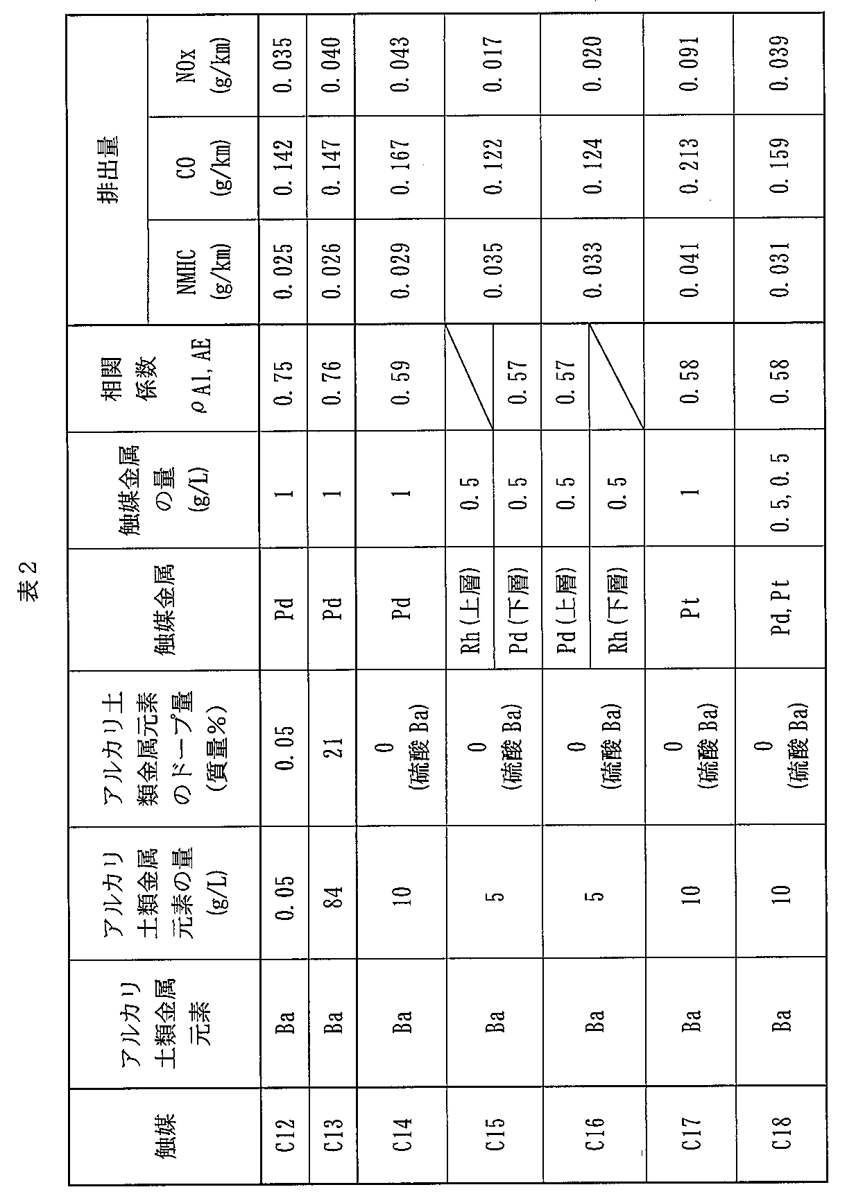
- the column “Amount of alkaline earth metal element” describes the mass of the alkaline earth metal element per unit volume of the base material.
- the column “Alkaline earth metal element dope” lists the amount of alkaline earth metal element doped based on the mass of alumina.
- the column “amount of catalyst metal” the mass of the catalyst metal per unit volume of the substrate is described.
- E is a combined value of each exhaust gas emission amount in the JC08 mode
- E C is a measured value of each exhaust gas emission amount in the JC08C mode
- E H is a measured value of each exhaust gas emission amount in the JC08H mode. It is.
- the combined values of the exhaust gas emissions thus obtained are shown in Tables 1 to 3 together with other physical property values.
- the catalysts C1 to C13 and C19 to C23 had better HC purification performance than the catalysts C14 to C18.
- FIG. 4 is a graph showing an example of the relationship between the amount of barium per unit volume of the substrate and the NO x emission amount.
- FIG. 4 shows the NO x emission amounts of the catalysts C1 to C4, C12 and C13, and C19 and C20.
Landscapes
- Chemical & Material Sciences (AREA)
- Engineering & Computer Science (AREA)
- Chemical Kinetics & Catalysis (AREA)
- Materials Engineering (AREA)
- Organic Chemistry (AREA)
- Combustion & Propulsion (AREA)
- Mechanical Engineering (AREA)
- Health & Medical Sciences (AREA)
- General Engineering & Computer Science (AREA)
- Toxicology (AREA)
- Biomedical Technology (AREA)
- Environmental & Geological Engineering (AREA)
- Analytical Chemistry (AREA)
- General Chemical & Material Sciences (AREA)
- Oil, Petroleum & Natural Gas (AREA)
- Emergency Medicine (AREA)
- Catalysts (AREA)
- Exhaust Gas Treatment By Means Of Catalyst (AREA)
Abstract
Description



この排ガス浄化用触媒1は、基材10と、基材10上に形成された触媒層20とを備えている。
パラジウム及び/又は白金は、典型的には、アルカリ土類金属元素がドープされたアルミナ上に担持されている。このパラジウム及び/又は白金は、HC及びCOの酸化反応並びにNOxの還元反応を触媒する役割を担っている。
まず、触媒層20の表面と触媒層20の基材10側の面との間を350等分して得られる350個の面を考える。そして、これら350個の面と触媒層20の主面に垂直な直線との350個の交点を考える。以下、これら350個の交点を、点Pi(i=1,2,…,350;以下同様)と呼ぶ。



この排ガス浄化用触媒1は、基材10と、基材10上に形成された第1触媒層20Aと、第1触媒層20A上に形成された第2触媒層20Bとを含んでいる。この第1触媒層20Aは、図1を参照しながら説明した触媒層20と同様の構成を有している。即ち、この排ガス浄化用触媒1は、第2触媒層20Bを更に備えていること以外は、図1を参照しながら説明した排ガス浄化用触媒と同様の構成を有している。
第2触媒層20Bは、典型的には、アルカリ土類金属元素がドープされたアルミナを含んでいない。第2触媒層20Bは、アルカリ土類金属元素がドープされたアルミナを含んでいてもよい。但し、この場合、典型的には、第2触媒層20Bにおける基材10の単位容積当りのアルカリ土類金属元素の含有量は、第1触媒層20Aにおける基材10の単位容積当りのアルカリ土類金属元素の含有量と比較してより少なくする。
この排ガス浄化用触媒1は、基材10と、基材10上に形成された第2触媒層20Bと、第2触媒層20B上に形成された第1触媒層20Aとを含んでいる。即ち、この排ガス浄化用触媒1は、第1触媒層20Aと第2触媒層20Bとの積層順が逆転していること以外は、図2を参照しながら説明した排ガス浄化用触媒と同様の構成を有している。
アルカリ土類金属元素がドープされたアルミナを、以下のようにして調製した。即ち、まず、硝酸アルミニウムとアルカリ土類金属元素の炭酸塩とクエン酸とを含んだ混合水溶液を準備した。次に、この混合水溶液に、ヒドラジンを添加した。その後、反応系を70℃で24時間に亘って攪拌し、沈殿物を得た。この沈殿物を濾別し、得られた濾過ケークを乾燥させた。次いで、得られた固体を、900℃で5時間に亘って焼成した。このようにして、アルカリ土類金属元素がドープされたアルミナを得た。
10質量%のバリウムがドープされたアルミナを準備した。以下、これを「BaアルミナBA1」と呼ぶ。
0.1質量%のバリウムがドープされたアルミナを準備した。以下、これを「BaアルミナBA2」と呼ぶ。
20質量%のバリウムがドープされたアルミナを準備した。以下、これを「BaアルミナBA3」と呼ぶ。
100gのBaアルミナBA3の代わりに400gのBaアルミナBA3を使用し、100gのCZ酸化物の代わりに50gのCZ酸化物を使用したこと以外は、スラリーS3と同様にして、スラリーを製造した。以下、このスラリーを「スラリーS4」と呼ぶ。
100gのBaアルミナBA1の代わりに50gのBaアルミナBA1を使用し、100gのCZ酸化物の代わりに50gのCZ酸化物を使用し、1gのパラジウムを含んだ硝酸パラジウムの代わりに0.5gのパラジウムを含んだ硝酸パラジウムを使用したこと以外は、スラリーS1と同様にして、スラリーを調製した。以下、このスラリーを「スラリーS5」と呼ぶ。
スラリーS6を、上記基材上に塗布した。次いで、これを250℃で1時間に亘り乾燥させた後、500℃で1時間に亘り焼成した。その後、スラリーS6が塗布された基材上に、スラリーS5を塗布した。続いて、これを250℃で1時間に亘り乾燥させた後、500℃で1時間に亘り焼成した。
1gのパラジウムを含んだ硝酸パラジウム水溶液の代わりに、1gの白金を含んだジニトロジアミン白金硝酸水溶液を使用したこと以外は、スラリーS1と同様にして、スラリーを調製した。以下、このスラリーを「スラリーS7」と呼ぶ。
1gのパラジウムを含んだ硝酸パラジウム水溶液の代わりに、0.5gのパラジウムを含んだ硝酸パラジウムと0.5gの白金を含んだジニトロジアミン白金硝酸との混合物の水溶液を使用したこと以外は、スラリーS1と同様にして、スラリーを調製した。以下、このスラリーを「スラリーS8」と呼ぶ。
10質量%のストロンチウムがドープされたアルミナを準備した。以下、これを「Srアルミナ」と呼ぶ。
10質量%のカルシウムがドープされたアルミナを準備した。以下、これを「Caアルミナ」と呼ぶ。
5質量%のバリウムと5質量%のストロンチウムとがドープされたアルミナを準備した。以下、これを「BaSrアルミナ」と呼ぶ。
0.05質量%のバリウムがドープされたアルミナを準備した。以下、これを「BaアルミナBA4」と呼ぶ。
21質量%のバリウムがドープされたアルミナを準備した。以下、これを「BaアルミナBA5」と呼ぶ。
90gのアルミナと、100gのCZ酸化物と、17gの硫酸バリウムと、1gのパラジウムを含んだ硝酸パラジウム水溶液とを混合し、スラリーを調製した。以下、このスラリーを「スラリーS14」と呼ぶ。
90gのアルミナの代わりに45gのアルミナを使用し、100gのCZ酸化物の代わりに50gのCZ酸化物を使用し、17gの硫酸バリウムの代わりに8.5gの硫酸バリウムを使用し、1gのパラジウムを含んだ硝酸パラジウムの代わりに0.5gのパラジウムを含んだ硝酸パラジウムを使用したこと以外は、スラリーS14と同様にして、スラリーを調製した。以下、このスラリーを「スラリーS15」と呼ぶ。
スラリーS5の代わりにスラリーS15を使用したこと以外は、触媒C6と同様にして、排ガス浄化用触媒を製造した。以下、この触媒を「触媒C16」と呼ぶ。
1gのパラジウムを含んだ硝酸パラジウム水溶液の代わりに、1gの白金を含んだジニトロジアミン白金硝酸水溶液を使用したこと以外は、スラリーS14と同様にして、スラリーを調製した。以下、このスラリーを「スラリーS16」と呼ぶ。
1gのパラジウムを含んだ硝酸パラジウム水溶液の代わりに、0.5gのパラジウムを含んだ硝酸パラジウムと0.5gの白金を含んだジニトロジアミン白金硝酸との混合物の水溶液を使用したこと以外は、スラリーS14と同様にして、スラリーを調製した。以下、このスラリーを「スラリーS17」と呼ぶ。
1質量%のバリウムがドープされたアルミナを準備した。以下、これを「BaアルミナBA6」と呼ぶ。
BaアルミナBA3の代わりにBaアルミナBA1を使用したこと以外は、スラリーS4と同様にして、スラリーを調製した。以下、このスラリーを「スラリーS19」と呼ぶ。
BaアルミナBA1の代わりにBaアルミナBA6を使用したこと以外は、スラリーS5と同様にして、スラリーを調製した。以下、このスラリーを「スラリーS20」と呼ぶ。
セリウム酸化物とジルコニウム酸化物とランタン酸化物との複合酸化物を準備した。この複合酸化物では、セリウム元素とジルコニウム元素とランタン元素とのモル比は、5:3:2とした。以下、この複合酸化物を「CZL酸化物」と呼ぶ。
セリウム酸化物とジルコニウム酸化物とランタン酸化物とイットリウム酸化物との複合酸化物を準備した。この複合酸化物では、セリウム元素とジルコニウム元素とランタン元素とイットリウム元素とのモル比は、5:3:1:1とした。以下、この複合酸化物を「CZLY酸化物」と呼ぶ。
触媒C1乃至C23の各々について、上述した相関係数ρAl,AEを、以下のようにして求めた。


まず、触媒C1乃至C23の各々について、6万kmの走行に相当する耐久試験を行った。次に、これらを1.0Lの排気量を有するエンジンを備えた実機車両に搭載した。続いて、この実機車両をJC08Cモード(コールドスタートによるJC08モード)及びJC08Hモード(ホットスタートによるJC08モード)で走行させ、各モードにおける非メタン炭化水素(NMHC)、CO及びNOxの排出量を測定した。そして、各モードで得られた排出量を次式に代入し、JC08モードによるNMHC、CO及びNOx排出量のコンバイン値を求めた。

Claims (10)
- 基材と、
前記基材上に形成され、パラジウム及び/又は白金と、アルカリ土類金属元素がドープされたアルミナとを含み、下記式(1)により与えられる相関係数ρAl,AEが0.75以上である第1触媒層とを具備した排ガス浄化用触媒。




iは1乃至350の自然数であり、
IAl,iは、前記第1触媒層を厚み方向に350等分して得られる面と前記第1触媒層の主面に垂直な線との350個の交点のうちi番目の交点において、電子線マイクロアナライザを用いて測定したアルミニウムの特性X線強度であり、
IAl,avは、下記式(5)により与えられる前記IAl,iの相加平均値であり、
IAE,avは、下記式(6)により与えられる前記IAE,iの相加平均値である。

- 前記相関係数ρAl,AEは0.79以上である請求項1に記載の排ガス浄化用触媒。
- 前記アルカリ土類金属元素はバリウムである請求項1又は2に記載の排ガス浄化用触媒。
- 前記第1触媒層における前記基材の単位容積当りの前記アルカリ土類金属元素の含有量は0.1g/L乃至80g/Lの範囲内にある請求項1乃至3の何れか1項に記載の排ガス浄化用触媒。
- 前記アルカリ土類金属元素のドープ量は、前記アルカリ土類金属元素がドープされたアルミナの質量を基準として0.1質量%乃至20質量%の範囲内にある請求項1乃至4の何れか1項に記載の排ガス浄化用触媒。
- 前記第1触媒層における前記パラジウム及び/又は白金の含有量に対する前記アルカリ土類金属元素の含有量の質量比は0.1乃至80の範囲内にある請求項1乃至5の何れか1項に記載の排ガス浄化用触媒。
- 前記第1触媒層上に形成され且つロジウムを含んだ第2触媒層を更に具備した請求項1乃至6の何れか1項に記載の排ガス浄化用触媒。
- 前記基材と前記第1触媒層との間に介在し且つロジウムを含んだ第2触媒層を更に具備した請求項1乃至6の何れか1項に記載の排ガス浄化用触媒。
- 前記第2触媒層は前記アルカリ土類金属元素がドープされたアルミナを含んでいないか、又は、前記第2触媒層は前記アルカリ土類金属元素がドープされたアルミナを更に含み、前記第2触媒層における前記基材の単位容積当りの前記アルカリ土類金属元素の含有量は、前記第1触媒層における前記基材の単位容積当りの前記アルカリ土類金属元素の含有量と比較してより少ない請求項7又は8に記載の排ガス浄化用触媒。
- 基材と、
パラジウム及び/又は白金と、アルカリ土類金属元素がドープされたアルミナとを含んだスラリーを前記基材上に塗布することにより得られる触媒層と
を具備した排ガス浄化用触媒。
Priority Applications (4)
| Application Number | Priority Date | Filing Date | Title |
|---|---|---|---|
| CN200980150857.9A CN102256701B (zh) | 2008-12-19 | 2009-12-18 | 废气净化用催化剂 |
| EP09833507.8A EP2368630A4 (en) | 2008-12-19 | 2009-12-18 | EMISSION CONTROL CATALYST |
| JP2010543017A JP5323093B2 (ja) | 2008-12-19 | 2009-12-18 | 排ガス浄化用触媒 |
| US13/163,341 US8318632B2 (en) | 2008-12-19 | 2011-06-17 | Exhaust gas purification catalyst |
Applications Claiming Priority (2)
| Application Number | Priority Date | Filing Date | Title |
|---|---|---|---|
| JP2008324265 | 2008-12-19 | ||
| JP2008-324265 | 2008-12-19 |
Related Child Applications (1)
| Application Number | Title | Priority Date | Filing Date |
|---|---|---|---|
| US13/163,341 Continuation US8318632B2 (en) | 2008-12-19 | 2011-06-17 | Exhaust gas purification catalyst |
Publications (1)
| Publication Number | Publication Date |
|---|---|
| WO2010071205A1 true WO2010071205A1 (ja) | 2010-06-24 |
Family
ID=42268872
Family Applications (1)
| Application Number | Title | Priority Date | Filing Date |
|---|---|---|---|
| PCT/JP2009/071172 Ceased WO2010071205A1 (ja) | 2008-12-19 | 2009-12-18 | 排ガス浄化用触媒 |
Country Status (5)
| Country | Link |
|---|---|
| US (1) | US8318632B2 (ja) |
| EP (1) | EP2368630A4 (ja) |
| JP (1) | JP5323093B2 (ja) |
| CN (1) | CN102256701B (ja) |
| WO (1) | WO2010071205A1 (ja) |
Cited By (7)
| Publication number | Priority date | Publication date | Assignee | Title |
|---|---|---|---|---|
| JP2013166097A (ja) * | 2012-02-14 | 2013-08-29 | Toyota Motor Corp | 排気ガス浄化用触媒 |
| WO2013162029A1 (ja) * | 2012-04-27 | 2013-10-31 | トヨタ自動車株式会社 | 酸化鉄-ジルコニア系複合酸化物とその製造方法、および排ガス浄化触媒 |
| JP2013240737A (ja) * | 2012-05-18 | 2013-12-05 | Toyota Motor Corp | 排ガス浄化触媒 |
| JP2013240736A (ja) * | 2012-05-18 | 2013-12-05 | Toyota Motor Corp | 排ガス浄化触媒 |
| JP2013241328A (ja) * | 2012-04-27 | 2013-12-05 | Toyota Central R&D Labs Inc | 酸化鉄−ジルコニア系複合酸化物およびその製造方法 |
| WO2020067000A1 (ja) * | 2018-09-28 | 2020-04-02 | ユミコア日本触媒株式会社 | 排ガス浄化触媒、排ガスの浄化方法、及び排ガス浄化触媒の製造方法 |
| JP2021531956A (ja) * | 2018-07-27 | 2021-11-25 | ジョンソン、マッセイ、パブリック、リミテッド、カンパニーJohnson Matthey Public Limited Company | 改良されたtwc触媒を含有する高ドーパント担体 |
Families Citing this family (17)
| Publication number | Priority date | Publication date | Assignee | Title |
|---|---|---|---|---|
| JP5337876B2 (ja) | 2009-05-27 | 2013-11-06 | 株式会社キャタラー | 排ガス浄化用触媒及びその製造方法 |
| WO2010137657A1 (ja) | 2009-05-27 | 2010-12-02 | 株式会社 キャタラー | 排ガス浄化用触媒 |
| EP2444152A4 (en) | 2009-06-16 | 2013-07-31 | Cataler Corp | EMISSION CONTROL CATALYST, POWDER MATERIAL AND METHOD FOR PRODUCING THE EMISSION CONTROL CATALYST |
| CN102470363B (zh) * | 2009-07-24 | 2015-01-28 | 株式会社科特拉 | 废气净化用催化剂 |
| JP5938819B2 (ja) | 2011-10-06 | 2016-06-22 | ジョンソン、マッセイ、パブリック、リミテッド、カンパニーJohnson Matthey Public Limited Company | 排気ガス処理用酸化触媒 |
| GB201200781D0 (en) | 2011-12-12 | 2012-02-29 | Johnson Matthey Plc | Exhaust system for a lean-burn ic engine comprising a pgm component and a scr catalyst |
| GB201200784D0 (en) | 2011-12-12 | 2012-02-29 | Johnson Matthey Plc | Exhaust system for a lean-burn internal combustion engine including SCR catalyst |
| GB2497597A (en) | 2011-12-12 | 2013-06-19 | Johnson Matthey Plc | A Catalysed Substrate Monolith with Two Wash-Coats |
| GB201200783D0 (en) | 2011-12-12 | 2012-02-29 | Johnson Matthey Plc | Substrate monolith comprising SCR catalyst |
| JP2014168764A (ja) * | 2013-03-05 | 2014-09-18 | Toyota Central R&D Labs Inc | ディーゼル排ガス用酸化触媒及びそれを用いたディーゼル排ガスの浄化方法 |
| JPWO2015076403A1 (ja) * | 2013-11-22 | 2017-03-16 | 株式会社キャタラー | 排気ガス浄化用触媒 |
| JP6417333B2 (ja) * | 2013-12-13 | 2018-11-07 | 株式会社キャタラー | 排ガス浄化用触媒 |
| JP6742751B2 (ja) * | 2016-02-19 | 2020-08-19 | 株式会社キャタラー | 排ガス浄化用触媒材料及び排ガス浄化用触媒 |
| EP3424592A4 (en) * | 2016-03-01 | 2019-11-27 | Cataler Corporation | EMISSION CONTROL CATALYST |
| JP6623111B2 (ja) * | 2016-04-13 | 2019-12-18 | 株式会社キャタラー | 排ガス浄化用触媒 |
| EP3581269B1 (en) * | 2017-04-11 | 2022-09-28 | Cataler Corporation | Catalyst for exhaust gas purification and method of preparation |
| JP7195995B2 (ja) | 2019-03-27 | 2022-12-26 | 株式会社キャタラー | 排ガス浄化用触媒 |
Citations (5)
| Publication number | Priority date | Publication date | Assignee | Title |
|---|---|---|---|---|
| JPH07289896A (ja) * | 1994-04-26 | 1995-11-07 | Hitachi Ltd | 排ガス浄化触媒およびその製造方法 |
| JPH11207183A (ja) | 1997-11-20 | 1999-08-03 | Daihatsu Motor Co Ltd | 排気ガス浄化用触媒 |
| JP2001070791A (ja) * | 1999-09-03 | 2001-03-21 | Daihatsu Motor Co Ltd | 排気ガス浄化用触媒 |
| JP2008100230A (ja) * | 2001-11-30 | 2008-05-01 | Umicore Ag & Co Kg | 希薄混合気燃焼エンジンからの排出ガスにおける窒素酸化物の量を低減するための触媒 |
| JP2008253921A (ja) * | 2007-04-05 | 2008-10-23 | Cataler Corp | 排ガス浄化用触媒 |
Family Cites Families (48)
| Publication number | Priority date | Publication date | Assignee | Title |
|---|---|---|---|---|
| US4128506A (en) * | 1978-01-23 | 1978-12-05 | General Motors Corporation | Platinum-rhodium catalyst for automotive emission control |
| US5597771A (en) * | 1993-06-25 | 1997-01-28 | Engelhard Corporation | Layered catalyst composite |
| DE69503527T2 (de) * | 1994-01-20 | 1999-04-29 | Toyota Jidosha K.K., Toyota, Aichi | Katalysator zur Reinigung von Abgasen |
| DE69412780T2 (de) * | 1994-01-28 | 1999-05-12 | Evangelos G. Patras Papadakis | Dreiwegkatalysator mit Pt, Rh und Pd, alle mit separatem Träger |
| US5559073A (en) * | 1994-09-26 | 1996-09-24 | Beijing Huaxia Environmental Protection Company | Pollution control catalyst with mutual protective distributed-active-combinations each including noble-metal-atoms stably structured and protected therein |
| US5556825A (en) * | 1995-01-06 | 1996-09-17 | Ford Motor Company | Automotive catalysts with improved oxygen storage and metal dispersion |
| JP3799651B2 (ja) * | 1995-04-28 | 2006-07-19 | マツダ株式会社 | 排気ガス浄化用触媒 |
| JPH0910594A (ja) * | 1995-04-28 | 1997-01-14 | Mazda Motor Corp | 排気ガス浄化用触媒 |
| US5948723A (en) * | 1996-09-04 | 1999-09-07 | Engelhard Corporation | Layered catalyst composite |
| JPH10180099A (ja) * | 1996-12-20 | 1998-07-07 | Ngk Insulators Ltd | 排ガス浄化用触媒及び排ガス浄化システム |
| JPH10180041A (ja) * | 1996-12-20 | 1998-07-07 | Ngk Insulators Ltd | 排ガス浄化用触媒及び排ガス浄化システム |
| JP4092441B2 (ja) * | 1997-02-24 | 2008-05-28 | 日産自動車株式会社 | 排ガス浄化用触媒 |
| GB9713428D0 (en) * | 1997-06-26 | 1997-08-27 | Johnson Matthey Plc | Improvements in emissions control |
| US6221804B1 (en) * | 1998-01-27 | 2001-04-24 | Mazda Motor Corporation | Catalyst for purifying exhaust gas and manufacturing method thereof |
| KR100326747B1 (ko) * | 1998-03-09 | 2002-03-13 | 하나와 요시카즈 | 산소 과잉 배기 가스의 정화 장치 |
| GB9813367D0 (en) * | 1998-06-22 | 1998-08-19 | Johnson Matthey Plc | Catalyst |
| DE19847008A1 (de) * | 1998-10-13 | 2000-04-20 | Degussa | Stickoxid-Speicherkatalysator |
| DE19854794A1 (de) * | 1998-11-27 | 2000-05-31 | Degussa | Katalysator für die Reinigung der Abgase eines Dieselmotors |
| JP2000176298A (ja) * | 1998-12-11 | 2000-06-27 | Mazda Motor Corp | 排気ガス浄化用触媒及びその製造方法 |
| DE60042991D1 (de) * | 1999-07-09 | 2009-11-05 | Nissan Motor | Abgasreinigungskatalysator und Verfahren zu seiner Herstellung |
| US6391822B1 (en) * | 2000-02-09 | 2002-05-21 | Delphi Technologies, Inc. | Dual NOx adsorber catalyst system |
| GB0022786D0 (en) * | 2000-09-16 | 2000-11-01 | Johnson Matthey Plc | NOx-Trap composition |
| JP4573993B2 (ja) * | 2000-11-09 | 2010-11-04 | 日産自動車株式会社 | 排気ガス浄化用触媒及びその製造方法 |
| GB0028240D0 (en) * | 2000-11-20 | 2001-01-03 | Johnson Matthey Plc | Three-way catalyst composition |
| KR100492644B1 (ko) * | 2001-02-26 | 2005-06-02 | 미쓰비시 지도샤 고교(주) | 배기 가스 정화용 촉매 |
| US6777370B2 (en) * | 2001-04-13 | 2004-08-17 | Engelhard Corporation | SOx tolerant NOx trap catalysts and methods of making and using the same |
| US6764665B2 (en) * | 2001-10-26 | 2004-07-20 | Engelhard Corporation | Layered catalyst composite |
| US7071141B2 (en) * | 2002-10-24 | 2006-07-04 | Ford Global Technologies, Llc | Perovskite catalyst system for lean burn engines |
| US7329629B2 (en) * | 2002-10-24 | 2008-02-12 | Ford Global Technologies, Llc | Catalyst system for lean burn engines |
| US7022646B2 (en) * | 2003-01-31 | 2006-04-04 | Engelhard Corporation | Layered catalyst composite |
| US7385889B2 (en) * | 2003-03-03 | 2008-06-10 | Samsung Electronics Co., Ltd. | Method and apparatus for managing disc defect using temporary DFL and temporary DDS including drive and disc information disc with temporary DFL and temporary DDS |
| JP4460844B2 (ja) * | 2003-04-17 | 2010-05-12 | 株式会社アイシーティー | 排ガス浄化用触媒および排気ガスの浄化方法 |
| DE10335785A1 (de) * | 2003-08-05 | 2005-03-10 | Umicore Ag & Co Kg | Katalysatoranordnung und Verfahren zur Reinigung des Abgases von mager betriebenen Verbrennungsmotoren |
| US7875250B2 (en) * | 2003-12-11 | 2011-01-25 | Umicore Ag & Co. Kg | Exhaust treatment device, and methods of making the same |
| US7374729B2 (en) * | 2004-03-30 | 2008-05-20 | Basf Catalysts Llc | Exhaust gas treatment catalyst |
| CN1938089B (zh) * | 2004-03-30 | 2010-12-08 | 日挥通用株式会社 | 废气净化用催化剂和废气的净化方法 |
| US7737077B2 (en) * | 2004-11-25 | 2010-06-15 | Cataler Corporation | Catalyst for purifying exhaust gases |
| KR101051418B1 (ko) * | 2006-03-16 | 2011-07-22 | 인터내쇼날 카탈리스트 테크놀로지, 인코포레이티드 | 배기가스 정화용 촉매, 그 제조방법 및 이러한 촉매를이용한 배기가스의 정화방법 |
| US7749472B2 (en) * | 2006-08-14 | 2010-07-06 | Basf Corporation | Phosgard, a new way to improve poison resistance in three-way catalyst applications |
| US7550124B2 (en) * | 2006-08-21 | 2009-06-23 | Basf Catalysts Llc | Layered catalyst composite |
| US7517510B2 (en) * | 2006-08-21 | 2009-04-14 | Basf Catalysts Llc | Layered catalyst composite |
| EP1952876A1 (en) * | 2007-01-25 | 2008-08-06 | Nissan Motor Co., Ltd. | Exhaust gas purifying catalyst and manufacturing method thereof |
| US7754171B2 (en) * | 2007-02-02 | 2010-07-13 | Basf Corporation | Multilayered catalyst compositions |
| US8007750B2 (en) * | 2007-07-19 | 2011-08-30 | Basf Corporation | Multilayered catalyst compositions |
| US7879755B2 (en) * | 2007-08-09 | 2011-02-01 | Basf Corporation | Catalyst compositions |
| JP5337876B2 (ja) * | 2009-05-27 | 2013-11-06 | 株式会社キャタラー | 排ガス浄化用触媒及びその製造方法 |
| WO2010137657A1 (ja) * | 2009-05-27 | 2010-12-02 | 株式会社 キャタラー | 排ガス浄化用触媒 |
| EP2444152A4 (en) * | 2009-06-16 | 2013-07-31 | Cataler Corp | EMISSION CONTROL CATALYST, POWDER MATERIAL AND METHOD FOR PRODUCING THE EMISSION CONTROL CATALYST |
-
2009
- 2009-12-18 JP JP2010543017A patent/JP5323093B2/ja not_active Expired - Fee Related
- 2009-12-18 CN CN200980150857.9A patent/CN102256701B/zh not_active Expired - Fee Related
- 2009-12-18 WO PCT/JP2009/071172 patent/WO2010071205A1/ja not_active Ceased
- 2009-12-18 EP EP09833507.8A patent/EP2368630A4/en not_active Ceased
-
2011
- 2011-06-17 US US13/163,341 patent/US8318632B2/en not_active Expired - Fee Related
Patent Citations (5)
| Publication number | Priority date | Publication date | Assignee | Title |
|---|---|---|---|---|
| JPH07289896A (ja) * | 1994-04-26 | 1995-11-07 | Hitachi Ltd | 排ガス浄化触媒およびその製造方法 |
| JPH11207183A (ja) | 1997-11-20 | 1999-08-03 | Daihatsu Motor Co Ltd | 排気ガス浄化用触媒 |
| JP2001070791A (ja) * | 1999-09-03 | 2001-03-21 | Daihatsu Motor Co Ltd | 排気ガス浄化用触媒 |
| JP2008100230A (ja) * | 2001-11-30 | 2008-05-01 | Umicore Ag & Co Kg | 希薄混合気燃焼エンジンからの排出ガスにおける窒素酸化物の量を低減するための触媒 |
| JP2008253921A (ja) * | 2007-04-05 | 2008-10-23 | Cataler Corp | 排ガス浄化用触媒 |
Non-Patent Citations (1)
| Title |
|---|
| See also references of EP2368630A4 |
Cited By (12)
| Publication number | Priority date | Publication date | Assignee | Title |
|---|---|---|---|---|
| JP2013166097A (ja) * | 2012-02-14 | 2013-08-29 | Toyota Motor Corp | 排気ガス浄化用触媒 |
| WO2013162029A1 (ja) * | 2012-04-27 | 2013-10-31 | トヨタ自動車株式会社 | 酸化鉄-ジルコニア系複合酸化物とその製造方法、および排ガス浄化触媒 |
| JP2013241328A (ja) * | 2012-04-27 | 2013-12-05 | Toyota Central R&D Labs Inc | 酸化鉄−ジルコニア系複合酸化物およびその製造方法 |
| RU2573022C1 (ru) * | 2012-04-27 | 2016-01-20 | Тойота Дзидося Кабусики Кайся | Железооксидно-цирконийоксидный смешанный оксид, способ его получения и катализатор очистки выхлопных газов |
| JP2013240737A (ja) * | 2012-05-18 | 2013-12-05 | Toyota Motor Corp | 排ガス浄化触媒 |
| JP2013240736A (ja) * | 2012-05-18 | 2013-12-05 | Toyota Motor Corp | 排ガス浄化触媒 |
| JP2021531956A (ja) * | 2018-07-27 | 2021-11-25 | ジョンソン、マッセイ、パブリック、リミテッド、カンパニーJohnson Matthey Public Limited Company | 改良されたtwc触媒を含有する高ドーパント担体 |
| US11794170B2 (en) | 2018-07-27 | 2023-10-24 | Johnson Matthey Public Limited Company | TWC catalysts containing high dopant support |
| JP2023162315A (ja) * | 2018-07-27 | 2023-11-08 | ジョンソン、マッセイ、パブリック、リミテッド、カンパニー | 改良されたtwc触媒を含有する高ドーパント担体 |
| JP7791861B2 (ja) | 2018-07-27 | 2025-12-24 | ジョンソン、マッセイ、パブリック、リミテッド、カンパニー | 改良されたtwc触媒を含有する高ドーパント担体 |
| WO2020067000A1 (ja) * | 2018-09-28 | 2020-04-02 | ユミコア日本触媒株式会社 | 排ガス浄化触媒、排ガスの浄化方法、及び排ガス浄化触媒の製造方法 |
| US11446639B2 (en) | 2018-09-28 | 2022-09-20 | Umicore Shokubai Japan Co., Ltd. | Exhaust gas purification catalyst, exhaust gas purification method, and production method for exhaust gas purification catalyst |
Also Published As
| Publication number | Publication date |
|---|---|
| US20110245076A1 (en) | 2011-10-06 |
| JP5323093B2 (ja) | 2013-10-23 |
| US8318632B2 (en) | 2012-11-27 |
| CN102256701B (zh) | 2014-04-09 |
| CN102256701A (zh) | 2011-11-23 |
| EP2368630A4 (en) | 2013-07-31 |
| JPWO2010071205A1 (ja) | 2012-05-31 |
| EP2368630A1 (en) | 2011-09-28 |
Similar Documents
| Publication | Publication Date | Title |
|---|---|---|
| JP5323093B2 (ja) | 排ガス浄化用触媒 | |
| JP5337875B2 (ja) | 排ガス浄化用触媒 | |
| CN102448608B (zh) | 废气净化用催化剂及其制造方法 | |
| CN102802784B (zh) | 废气净化用催化剂、粉末材料及废气净化用催化剂的制造方法 | |
| KR101432330B1 (ko) | 배출 가스 정화용 촉매 | |
| JP5173282B2 (ja) | 排ガス浄化用触媒 | |
| JP5232401B2 (ja) | 排ガス浄化用触媒 | |
| WO2008004588A1 (en) | Exhaust gas purifying catalyst | |
| CN108472590A (zh) | 排气净化装置 | |
| WO2019065659A1 (en) | CATALYST FOR PURIFYING EXHAUST GASES | |
| JP5965982B2 (ja) | 排ガス浄化用触媒及びその製造方法 | |
| WO2008047742A1 (en) | Exhaust gas purification catalyst | |
| JP6339013B2 (ja) | 排気ガス浄化触媒用担体、排気ガス浄化用触媒及び排気ガス浄化用触媒構成体 | |
| JP6623111B2 (ja) | 排ガス浄化用触媒 | |
| JP5173180B2 (ja) | 排ガス浄化用触媒 | |
| WO2013039037A1 (ja) | 排気ガス浄化用触媒及び排気ガス浄化用触媒構成体 | |
| CN111315476A (zh) | 氮氧化物吸留材料和废气净化用催化剂 | |
| JP7228451B2 (ja) | 自動車用排ガス浄化触媒 | |
| WO2025121117A1 (ja) | 排ガス浄化触媒 |
Legal Events
| Date | Code | Title | Description |
|---|---|---|---|
| WWE | Wipo information: entry into national phase |
Ref document number: 200980150857.9 Country of ref document: CN |
|
| 121 | Ep: the epo has been informed by wipo that ep was designated in this application |
Ref document number: 09833507 Country of ref document: EP Kind code of ref document: A1 |
|
| WWE | Wipo information: entry into national phase |
Ref document number: 2010543017 Country of ref document: JP |
|
| REEP | Request for entry into the european phase |
Ref document number: 2009833507 Country of ref document: EP |
|
| WWE | Wipo information: entry into national phase |
Ref document number: 2009833507 Country of ref document: EP |
|
| NENP | Non-entry into the national phase |
Ref country code: DE |