WO2010073668A1 - モータ装置、装置及び回転子の駆動方法 - Google Patents
モータ装置、装置及び回転子の駆動方法 Download PDFInfo
- Publication number
- WO2010073668A1 WO2010073668A1 PCT/JP2009/007192 JP2009007192W WO2010073668A1 WO 2010073668 A1 WO2010073668 A1 WO 2010073668A1 JP 2009007192 W JP2009007192 W JP 2009007192W WO 2010073668 A1 WO2010073668 A1 WO 2010073668A1
- Authority
- WO
- WIPO (PCT)
- Prior art keywords
- rotor
- transmission member
- motor device
- state
- moving
- Prior art date
- Legal status (The legal status is an assumption and is not a legal conclusion. Google has not performed a legal analysis and makes no representation as to the accuracy of the status listed.)
- Ceased
Links
Images










Classifications
-
- H—ELECTRICITY
- H02—GENERATION; CONVERSION OR DISTRIBUTION OF ELECTRIC POWER
- H02N—ELECTRIC MACHINES NOT OTHERWISE PROVIDED FOR
- H02N2/00—Electric machines in general using piezoelectric effect, electrostriction or magnetostriction
-
- H—ELECTRICITY
- H02—GENERATION; CONVERSION OR DISTRIBUTION OF ELECTRIC POWER
- H02N—ELECTRIC MACHINES NOT OTHERWISE PROVIDED FOR
- H02N2/00—Electric machines in general using piezoelectric effect, electrostriction or magnetostriction
- H02N2/10—Electric machines in general using piezoelectric effect, electrostriction or magnetostriction producing rotary motion, e.g. rotary motors
- H02N2/101—Electric machines in general using piezoelectric effect, electrostriction or magnetostriction producing rotary motion, e.g. rotary motors using intermittent driving, e.g. step motors
-
- H—ELECTRICITY
- H02—GENERATION; CONVERSION OR DISTRIBUTION OF ELECTRIC POWER
- H02N—ELECTRIC MACHINES NOT OTHERWISE PROVIDED FOR
- H02N2/00—Electric machines in general using piezoelectric effect, electrostriction or magnetostriction
- H02N2/10—Electric machines in general using piezoelectric effect, electrostriction or magnetostriction producing rotary motion, e.g. rotary motors
-
- H—ELECTRICITY
- H02—GENERATION; CONVERSION OR DISTRIBUTION OF ELECTRIC POWER
- H02N—ELECTRIC MACHINES NOT OTHERWISE PROVIDED FOR
- H02N2/00—Electric machines in general using piezoelectric effect, electrostriction or magnetostriction
- H02N2/10—Electric machines in general using piezoelectric effect, electrostriction or magnetostriction producing rotary motion, e.g. rotary motors
- H02N2/16—Electric machines in general using piezoelectric effect, electrostriction or magnetostriction producing rotary motion, e.g. rotary motors using travelling waves, i.e. Rayleigh surface waves
Definitions
- the present invention relates to a motor device, a device, and a method for driving a rotor.
- This application claims priority based on Japanese Patent Application No. 2008-333925 for which it applied on December 26, 2008, and uses the content here.
- a motor device is used as an actuator for driving a turning machine.
- a motor device capable of generating a high torque, such as an electric motor or an ultrasonic motor, is widely known.
- motor devices that drive more precise parts such as the joint parts of humanoid robots (devices) have been demanded.
- Even in existing motors such as electric motors and ultrasonic motors, miniaturization, torque controllability, etc.
- An object of the aspect of the present invention is to provide a motor device that can generate a high torque, can easily control torque, and is suitable for downsizing.
- a motor device includes a rotor (SF), a transmission member (BT) hung on at least a part of an outer periphery of the rotor, and the transmission member connected to the transmission member.
- a transmission unit (AC) that moves a member, and a transmission operation between the rotor and the transmission member in a rotational force transmission state and a transmission operation that moves the transmission member by a certain distance and the transmission in a state in which the rotational force transmission state is eliminated
- CONT that causes the moving unit to perform a return operation to return the member to a predetermined position.
- the motor device (MT2) includes a rotor (SF), a transmission member (BT) hung on the rotor, and a transmission of a vibration wave in one direction of the transmission member.
- a control unit (CONT) is provided that rotates the rotor in a direction opposite to the one direction by causing the member to move in a wave-like manner.
- An apparatus includes an arm unit (ARM) and the motor device (MTR, MT2) described in the present embodiment for driving the arm unit.
- ARM arm unit
- MTR motor device
- the graph which shows the characteristic of a motor apparatus The figure which shows operation
- FIG. 1 is a schematic configuration diagram illustrating an example of a motor device MTR according to the present embodiment.
- the motor device MTR includes a rotor SF, a transmission member BT, a moving part AC, a support member BS, and a control part CONT.
- the motor device MTR is in a state where the rotor SF and the moving part AC are supported by the support member BS, and a transmission member BT connected to the moving part AC is hung on the rotor SF.
- the control unit CONT is electrically connected to the moving unit AC and can supply a control signal to the moving unit AC.
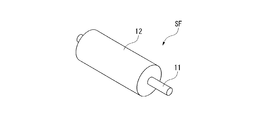
- FIG. 2 is a diagram illustrating a configuration of the rotor SF.
- the rotor SF is formed in a columnar shape, and includes a shaft portion 11 and a diameter-expanded portion 12.
- the shaft portion 11 is rotatably supported by a bearing portion 41 (see FIG. 1) of the support member BS via, for example, a bearing mechanism (not shown).
- the enlarged diameter portion 12 is a portion formed with a larger diameter than the shaft portion 11. That is, the enlarged diameter portion 12 has a larger diameter than the shaft portion 11.
- the shaft portion 11 and the enlarged diameter portion 12 are formed so as to have a common rotating shaft.
- the surface of the enlarged diameter portion 12 is an outer periphery (outer surface, outer peripheral surface) on which the transmission member BT is hung.
- the rotor SF is made of a conductive material such as aluminum. Alternatively or additionally, the rotor can be constructed using materials other than aluminum.
- the rotor SF has a detector (not shown) that can detect the outer peripheral speed of the enlarged diameter portion 12.
- the diameter of the enlarged diameter part 12 can be set to about 10 mm, for example.
- the diameter of the expanded diameter portion 12 can be about 0.5, 1, 2, 3, 4, 5, 6, 7, 8, 9, 10, 15, 20, 25, or 30 mm or more.
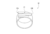
- FIG. 3 is a diagram illustrating a configuration of the transmission member BT.
- the transmission member BT is formed in a band shape and is wound around the enlarged diameter portion 12 of the rotor SF.
- the illustration of the rotor SF is omitted.
- the transmission member BT is made of a conductive material such as steel. Alternatively or additionally, the transmission member BT can be constructed using materials other than steel.
- the transmission member BT is in a state where it is wound around the enlarged diameter portion 12 by, for example, one rotation. That is, the substantial number of turns of the transmission member BT with respect to the enlarged diameter portion 12 is about 1.0.
- the substantial number of turns of the transmission member BT relative to the enlarged diameter portion 12 is, for example, about 0.2, 0.4, 0.6, 0.8, 1.2, 1.4, 1 .6, 1.8, or 2.0 or higher.
- the intersecting portion 21 of the transmission member BT has a cross belt structure. Specifically, at the intersecting portion 21, the first end 22A of the transmission member BT is divided into two and the width of the second end 22B of the transmission member BT is narrow. For this reason, the transmission member BT intersects with the second end 22B disposed between the two ends of the first end 22A. The first end 22A and the second end 22B of the transmission member BT are respectively connected to the moving part AC.
- a plurality of, for example, three such transmission members BT are provided along the axial direction of the rotor SF.
- the three transmission members BT have the same width (dimension in the rotation axis direction).
- the intersecting portions 21 of the three transmission members BT are arranged at positions shifted at equal angles in the circumferential direction of the rotor SF, specifically at positions shifted by 120 °.
- the friction coefficients between the three transmission members BT and the enlarged diameter portion 12 of the rotor SF are each formed to be, for example, 0.3.
- the number of transmission members BT can be, for example, 1, 2, 4, 5, 6, 7, 8, 9, or 10 or more for one rotor SF.
- the friction coefficient between the transmission member BT and the enlarged diameter portion 12 of the rotor SF is about 0.1, 0.2, 0.3, 0.4, 0.5. , 0.6, 0.7, 0.8, or 0.9 or higher.
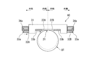
- FIG. 4 is a diagram illustrating a configuration of the moving unit AC.
- FIG. 4 shows a configuration in which the moving part AC is connected to the transmission member BT. At least a part of the moving part AC is provided at the intersection part 21 of the transmission member BT or in the vicinity thereof.
- the moving part AC includes a holding member 31, an electrostrictive element 32, a connection part 33, and a spring mechanism 34.
- the holding member 31 is formed substantially along the tangential direction of the circumference of the rotor SF at the intersecting portion 21.
- the holding member 31 has a longitudinal direction in the tangential direction. In other words, the holding member 31 has a long axis in the tangential direction.
- the holding member 31 has recesses 31a at both ends in the longitudinal direction. Openings 31b are provided at the bottoms of the recesses 31a. As shown in FIG. 1, each holding member 31 is fixed to the support member BS.
- the electrostrictive element 32 is provided in each recess 31 a of the holding member 31. For this reason, a pair of electrostrictive elements 32 are provided so as to sandwich the intersecting portion 21 as a reference position.
- Each of the pair of electrostrictive elements 32 (the first electrostrictive element 32A and the second electrostrictive element 32B) has a hollow cylindrical shape (cylindrical shape).
- the pair of electrostrictive elements 32 (the first electrostrictive element 32A and the second electrostrictive element 32B) can be deformed in directions opposite to each other with respect to the intersecting portion 21 which is the reference position (outward with respect to the intersecting portion 21) To be extensible).
- first electrostrictive element 32A and the second electrostrictive element 32B for example, a piezoelectric element or the like is used. Alternatively or additionally, an element other than the piezoelectric element can be used as the first electrostrictive element 32A and the second electrostrictive element 32B.
- the connecting portion 33 is a portion that connects the first end portion 22A of the transmission member BT and the first electrostrictive element 32A, and connects the second end portion 22B and the second electrostrictive element 32B.
- the connection part 33 has a flange member 33a and a rod member 33b.
- the flange member 33a is provided so as to be in contact with the end face of the first electrostrictive element 32A and the end face of the second electrostrictive element 32B, respectively.
- the rod member 33b is provided integrally with the flange member 33a.
- the rod member 33b passes through the first electrostrictive element 32A and the second electrostrictive element 32B, and is provided so as to pass through the opening 31b of the recess 31a.
- the tip of the rod member 33b is connected to the first end 22A and the second end 22B of the transmission member BT, respectively.
- the spring mechanism 34 is configured to press the flange member 33 a toward the intersecting portion 21.
- the spring mechanism 34 is configured by, for example, a plate spring member 34a.
- one end of the leaf spring member 34 a is connected to the outer surface of the flange member 33 a via a nut or the like, folded back so as to bypass the flange member 33 a, and the other end is fixed to the end surface of the holding member 31.
- the other end side of the leaf spring member 34 a is bent so as to come into contact with the end surface of the holding member 31.
- FIG. 5 is a block diagram showing a configuration of the control unit CONT.
- the control unit CONT includes a position command unit 51, a calculation unit 52, a controller 53, and an amplifier 54.
- the motor device MTR can detect the output value of the moving unit AC by an encoder. Based on the detected value of the encoder, the control unit CONT converts the deformation amount and deformation speed error of the first electrostrictive element 32A and the second electrostrictive element 32B into a thrust and sets it as a command value for the moving unit AC.
- FIGS. 6 and 7 show the configuration of the transmission member BT in a state where it is not hung on the rotor SF.
- the first electrostrictive element 32A and the second electrostrictive element 32B perform the same operation (however, the moving direction of the transmission member BT is reversed).
- One electrostrictive element 32A will be described as a representative.
- the flange member 33a is pressed toward the intersecting portion 21 by the spring mechanism 34.
- the first electrostrictive element 32A is deformed so as to expand.
- the first electrostrictive element 32 ⁇ / b> A extends outward with respect to the intersecting portion 21 with the abutting end with the holding member 31 as a fixed end.
- the force due to the deformation acts on the direction away from the intersecting portion 21 (hereinafter referred to as “outside”). This force presses the flange member 33a outward.
- the first electrostrictive element 32A is deformed so as to contract, and the deformation is pushed to the flange member 33a.
- the pressure drops.
- the flange member 33a moves in a direction approaching the reference position (hereinafter referred to as “inside”), and the rod member 33b pushes the end of the transmission member BT inward. .
- the end of the transmission member BT moves inward.
- Equation (2) is an equation representing effective tension using T1.
- FIG. 8 is a graph showing the relationship between the effective winding angle ⁇ and the value of the coefficient portion when the friction coefficient ⁇ is changed.
- the horizontal axis of the graph indicates the effective winding angle ⁇
- the vertical axis of the graph indicates the value of the coefficient portion.
- the value of the coefficient portion is 0.8 or more when the effective winding angle ⁇ is 300 ° or more. From this, when the friction coefficient ⁇ is 0.3, by setting the effective winding angle ⁇ to 300 ° or more, the force of 80% or more of the tension T1 by the first electrostrictive element 32A causes the torque of the rotor SF. It can be seen that it contributes to In addition to the winding angle, it is estimated from the graph of FIG. 8 that, for example, the value of the coefficient portion increases as the friction coefficient between the transmission member BT and the rotor SF increases.
- the magnitude of the torque is uniquely determined by the tension T1 of the first electrostrictive element 32A, and is independent of, for example, the moving distance of the transmission member BT. Therefore, for example, the piezo element used for the first electrostrictive element 32A and the second electrostrictive element 32B can produce a force of several hundreds of newtons or more even if it is a small element of about several millimeters. Power can be granted.
- the control unit CONT can drive the rotor SF by controlling the first electrostrictive element 32A and the second electrostrictive element 32B.
- the control unit CONT can include at least a drive mode and a return mode.
- the control unit CONT first deforms the first electrostrictive element 32A and the second electrostrictive element 32B so that the first end 22A and the second end 22B move outward (tension).
- Generation operation tension generation mode
- a tension T1 is generated on the first end 22A side of the transmission member BT
- a tension T2 is generated on the second end 22B side of the transmission member BT. Accordingly, an effective tension (T1-T2) is generated in the transmission member BT.
- the control unit CONT keeps the state where the effective tension is generated in the transmission member BT so that the first end 22A of the transmission member BT moves outward and the second end.
- the first electrostrictive element 32A and the second electrostrictive element 32B are deformed so that the portion 22B moves inward (drive operation, drive mode).
- the control unit CONT makes the moving distance of the first end 22A equal to the moving distance of the second end 22B.
- the transmission member BT moves in a state where a frictional force is generated between the transmission member BT and the rotor SF, and the rotor SF rotates in the ⁇ direction in the drawing along with the movement.
- the friction coefficient ⁇ between the transmission member BT and the rotor SF is 0.3, and the transmission member BT is wound around the enlarged diameter portion 12 of the rotor SF by one rotation (360 °). . Therefore, referring to the graph of FIG. 8, a force of about 85% of the tension T1 of the first electrostrictive element 32A is transmitted to the rotor SF as a torque.
- the controller CONT moves the first end 22A and the second end 22B by a predetermined distance, and then returns the first end 22A to the driving start position (predetermined position) as shown in FIG.
- the first electrostrictive element 32A is deformed so that the second end 22B does not move.
- the first end 22A moves inward, and the winding of the transmission member BT becomes loose. That is, the effective tension applied to the transmission member BT is released. In this state, no frictional force is generated between the transmission member BT and the rotor SF, and the rotor SF continues to rotate due to inertia.
- the control unit CONT deforms the second electrostrictive element 32B so that the second end 22B returns to the driving start position (predetermined position) as shown in FIG. Let By this operation, the second end 22B of the transmission member BT returns to the drive start position (predetermined position) while the winding of the transmission member BT is loose, that is, the effective tension is not generated (return operation, Return mode).
- the control unit CONT deforms the first electrostrictive element 32A and moves the first end 22A outward as shown in FIG. (Tension generation operation, tension generation mode).
- tension generation operation tension generation mode
- the tension T1 is generated on the first end 22A side
- the tension T2 is generated on the second end 22B side almost simultaneously with the return of the second end 22B to the drive start position.
- it will be in the state similar to the state (state of FIG. 9) which applied effective tension to transmission member BT at the time of a drive start.
- the control unit CONT deforms the first electrostrictive element 32A so that the first end 22A of the transmission member BT moves outward, and the second end 22B is inward.
- the second electrostrictive element 32B is deformed so as to move to (driving operation, driving mode).
- the moving distance of the first end 22A and the moving distance of the second end 22B are made equal.
- the transmission member BT moves in a state where a frictional force is generated between the transmission member BT and the rotor SF, and the rotor SF rotates in the ⁇ direction along with the movement.
- control unit CONT releases the effective tension added to the transmission member BT again.
- control unit CONT moves the first end 22A and the second end 22B of the transmission member BT so as to return to the start position (return operation, return mode).
- the control unit CONT causes the moving unit AC to repeatedly perform the driving operation and the return operation, so that the rotor SF continues to rotate in the ⁇ direction.
- the tension generation mode, the drive mode, and the return mode are repeated in order.
- three combinations of the transmission member BT and the moving part AC are provided along the rotation axis direction of the rotor SF, and a three-phase structure is formed. Therefore, the three-phase transmission member BT and the moving part AC can be sequentially driven for each phase.
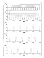
- FIG. 14 is a graph showing the relationship between tension and time when the three-phase transmission member BT and the moving part AC are alternately driven.
- the horizontal axis of the graph indicates time, and the vertical axis of the graph indicates tension.
- the broken line, the alternate long and short dash line, and the alternate long and two short dashes line in the graph indicate driving of each phase.
- the solid line in the graph indicates the tension in the entire rotor SF.
- Parts (b) to (d) of FIG. 14 show driving of each phase in part (a) of FIG.
- the driving time for one phase is set to 0.01 seconds.
- the vibration width of the tension is suppressed to be small, and stable driving can be performed.
- the moving part AC performs the driving operation and the returning operation in a state where the transmission member BT is hung on at least a part of the rotor SF
- Euler's friction belt theory is used.
- the torque is uniquely determined by the one tension applied to the transmission member BT. Therefore, it is possible to add a high torque to the rotor SF without attaching a speed reducer or the like or even with a small moving part AC.
- the small motor apparatus MTR which can generate a high torque can be obtained.
- the rotor SF can be rotated with high efficiency.
- the torque transmitted to the rotor SF can be controlled by controlling the magnitude of the tension T1 by the first electrostrictive element 32A, so that the torque control can be easily performed. it can.
- the present embodiment is different from the first embodiment in that the elastic deformation of the transmission member BT is used during the operation of the motor device MTR. Therefore, the configuration of the motor device MTR can be the same as that of the first embodiment except that the transmission member BT can be elastically deformed.
- the spring constant of the transmission member BT is k.
- the friction belt theory of Euler set the retaining force T C of the rotor SF, as shown by the following formula (3).
- the holding force T C is the force required to reactivate AIBO rotor SF at rest.
- the driving operation of the rotor SF will be mainly described with reference to FIGS.
- the configuration of the motor device is schematically shown for easy understanding. Therefore, for example, the winding angle of the transmission member BT is described so as to be different from the actual configuration.
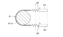
- each position of the part 22B is defined as an origin position 0. Therefore, in a state where both the first end 22A and the second end 22B of the transmission member BT are disposed at the origin position 0, no frictional force is generated between the transmission member BT and the rotor SF.
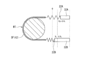
- the control unit CONT deforms the first electrostrictive element 32A so that the tension T1 on the first end 22A side of the transmission member BT becomes the target tension T1e .
- the one end 22A is moved to the outside of ⁇ X 1 (in FIG. 16, the right side of the paper).
- the control unit CONT deforms the second electrostrictive element 32B so that the second end 22B is set to the inner side of ⁇ X 2 (in FIG. 16, the tension T2 on the second end 22B side becomes the target tension T 2e .
- torque is transmitted from the transmission member BT to the rotor SF.
- the relationship of Expression (7) is established between ⁇ X1 and ⁇ X2.
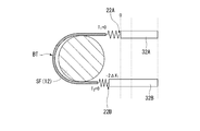
- the control unit CONT moves the first end 22A to the origin position 0 and the second end 22B from the origin position 0 (in FIG. 18, the left side of the page).
- the first electrostrictive element 32A and the second electrostrictive element 32B are deformed at the same time so as to move to.
- the transmission member BT becomes loosen only 2DerutaX 1, this result, a gap is generated between the transmission member BT and the rotor SF.
- the rotor SF is in an inertial rotation state without receiving a frictional force by the transmission member BT.
- the control unit CONT does not move the first end 22A, only the second end 22B is the origin position.
- the second electrostrictive element 32B is deformed so as to return to zero.
- both the first end 22A and the second end 22B return to the origin position 0.
- the rotor SF is in an inertial rotation state without receiving frictional force by the transmission member BT.
- the first end 22A and the second end 22B are moved to the origin position 0 in a state where the rotor SF is rotated without giving resistance to the rotor SF due to frictional force.
- the control part CONT detects the outer peripheral speed v of the enlarged diameter part 12 by means of a detector provided in the rotor SF.
- the control unit CONT determines the moving distance of the first end 22A and the second end 22B based on the detection result.
- the initial position of the first end portion 22A X 1 the initial position of the second end portion 22B was set to X 2.
- the same environment as the stationary state of the rotor SF is necessary.
- the relative speed between the outer periphery of the enlarged diameter portion 12 of the rotor SF and the transmission member BT needs to be zero.
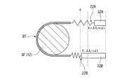
- the initial position of the first end 22A and the initial position of the second end 22B it is necessary to consider the moving distance per predetermined time of the outer periphery of the enlarged diameter portion 12.
- the initial position of the first end 22A is set as X 1 + v ⁇ t
- the initial position of the second end 22B is set as X 2 ⁇ v ⁇ t.
- ⁇ t include a sampling time of the control unit CONT.
- the control unit CONT deforms the first electrostrictive element 32A so that the tension T1 on the first end 22A side of the transmission member BT becomes the target tension T1e .
- the one end 22A is moved to the outside of ⁇ X 1 (for example, on the right side of the paper surface in FIG. 20).
- the control unit CONT deforms the second electrostrictive element 32B so that the second end 22B is set to the inner side of the second end 22B by ⁇ X 2 so that the tension T2 on the second end 22B side becomes the target tension T 2e (for example, FIG. 20).
- ⁇ X 1 for example, on the right side of the paper surface in FIG. 20
- the control unit CONT deforms the second electrostrictive element 32B so that the second end 22B is set to the inner side of the second end 22B by ⁇ X 2 so that the tension T2 on the second end 22B side becomes the target tension T 2e (for example, FIG. 20).
- ⁇ X 1 for example, on the right side of the
- the first end portion 22A is moved to the outside (for example, the right side of the page in FIG. 20) by X 1 + v ⁇ t + ⁇ X 1 with respect to the origin position 0.
- the second end portion 22B is moved outward (for example, on the right side of the sheet in FIG. 20) by X 2 ⁇ v ⁇ t ⁇ X 1 with respect to the origin position.
- the control unit CONT changes the first end 22A to the origin position 0 and the second end 22B to the inside of the origin position 0 (for example, the left side of the page in FIG. 18). While the first electrostrictive element 32A and the second electrostrictive element 32B are deformed at the same time and a gap is generated between the transmission member BT and the rotor SF, the second end without moving the first end 22A. The second electrostrictive element 32B is deformed so that only the portion 22B returns to the origin position 0. By this operation, both the first end 22A and the second end 22B return to the origin position 0. The return operation can be performed as the same operation regardless of the rotation speed of the rotor SF.
- the rotor SF can be made by repeating the driving operation and the returning operation.
- the driving operation and the returning operation are repeated as long as the value of X 1 + v ⁇ t + ⁇ X 1 does not exceed the maximum deformation amount of the first electrostrictive element 32A. Can continue to transmit torque.
- FIG. 21 is a graph showing the amount of change in the first electrostrictive element 32A and the second electrostrictive element 32B when the drive operation and the return operation are repeated.
- the horizontal axis of the graph indicates time, and the vertical axis of the graph indicates the amount of change.
- the graph indicated by the solid line in the figure indicates the amount of change of the first electrostrictive element 32A, and the graph indicated by the broken line in the figure indicates the amount of change of the second electrostrictive element 32B. As shown in the figure, it can be seen that the amount of change of the first electrostrictive element 32A increases as the drive operation (1) and the return operation (2) are repeated.
- the effective torque N e in the present embodiment includes a time t all required for performing one cycle of the drive operation and the return operation, a time t e from the start of transmission of the effective tension until the rotor SF enters an inertia state, and a target effective tension. It depends on T goal and the radius R of the enlarged diameter portion 12 of the rotor SF. Specifically, it is represented by the following formula (8).
- the effective deformation of the transmission member BT is made by using the elastic deformation of the transmission member BT and setting the relative speed between the outer periphery of the enlarged diameter portion 12 of the rotor SF and the transmission member BT to zero.
- the rotor SF is dynamically rotated while accelerating or decelerating by repeatedly performing the driving operation transmitted to the rotor SF and the returning operation of simultaneously moving the first end 22A and the second end 22B inward. Can do. Further, even with a small moving part AC, the rotor SF can be rotated with high efficiency.
- the motor device MT ⁇ b> 2 is configured to rotate the rotor SF by propagating a traveling wave to the transmission member BT wound around the rotor SF.
- the transmission member BT is wound around the rotor SF in a state where no tension is applied. By not applying tension to the transmission member BT, traveling waves are easily propagated.
- the transmission member BT has a first end 22A connected to, for example, a vibration device 61, and a second end 22B connected to, for example, a vibration suppressor 62.
- the vibration device 61 and the vibration suppression device 62 are connected to the control unit CONT.
- the control unit CONT controls the operations of the vibration exciting device 61 and the vibration suppressing device 62.
- the control unit CONT drives the vibration device 61 to propagate a traveling wave (for example, 42.2 kHz) to the transmission member BT.
- a traveling wave for example, 42.2 kHz
- the surface of the transmission member BT performs an elliptical motion. Due to the elliptical motion, the rotor SF rotates in a direction opposite to the propagation direction of the traveling wave.
- control unit CONT drives the vibration suppressor 62 to change the load resistance provided in the vibration suppressor 62 to obtain impedance matching and reduce the traveling wave reflection at the second end 22B.
- standing waves propagating to the transmission member BT are suppressed.
- the control unit CONT can reverse the rotation direction of the rotor SF by reversing the propagation direction of the traveling wave.
- the rotor SF can be rotated by propagating the traveling wave to the transmission member BT, a small size can be used as long as the traveling wave can be propagated to the transmission member BT. Even if it is a thing, it becomes possible to add a high torque to the rotor SF. Further, according to the present embodiment, the rotor SF can be rotated with high efficiency.
- FIG. 23 is a diagram illustrating a configuration in which the motor device MTR is applied to, for example, a robot arm.
- the motor device MTR is connected to a robot arm ARM (arm part) via a coupling CPL. Since the motor device MTR of the above embodiment is small and can output a high torque, the robot arm ARM can be driven with high accuracy.
- the motor device MTR of the above embodiment can also be applied to a joint portion of a robot (device), a drive unit of a machine tool (device), and the like.
- the rotor is solid.
- the present invention is not limited to this.
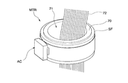
- the rotor SF may have a hollow configuration as shown in FIG. 24A, for example.
- the rotor SF has a through portion 71 that penetrates in the direction of the rotation axis.
- the penetrating portion 71 is provided with a cylindrical bearing 70.
- the rotor SF is rotatable around the bearing 70.
- wiring 72 and the like can be arranged inside the bearing 70.
- the rotor SF as a wiring pipe.
- the rotation transmission state has been described as a state in which the rotor SF and the transmission member BT do not slip due to frictional force, but the rotation transmission state is not limited thereto.
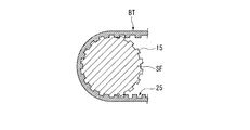
- the state in which the rotor SF and the transmission member BT are engaged may be set as the rotation transmission state.
- the rotor SF is provided with a convex portion 15
- the transmission member BT is provided with a concave portion 25 so as to mesh with the convex portion 15.
- the configuration may be such that the rotational force is transmitted by engaging the convex portion 15 of the rotor SF and the concave portion 25 of the transmission member BT.
- the direction in which the convex portion 15 of the rotor SF is provided is not particularly limited, and may be a random direction, a rotation axis direction of the rotor SF, a circumferential direction of the rotor SF, or the like. Moreover, in this embodiment, it is good also as a structure which provides a recessed part in the rotor SF and provides a convex part in the transmission member BT.
- the size of the convex portion (for example, convex portion 15) or the concave portion (for example, concave portion 25) is not particularly limited, but is small enough to allow the transmission member BT to be loosened by the moving portion AC.
- the moving portion AC is small enough to cause a gap between the rotor SF and the transmission member BT.
- the engagement in the present embodiment is, for example, that the convex portion 15 of the rotor SF and the concave portion 25 of the transmission member BT are engaged, and the convex portion 15 of the rotor SF and the concave portion 25 of the transmission member BT are fitted. Fitting, the convex portion 15 of the rotor SF and the concave portion 25 of the transmission member BT are joined together, and the convex portion 15 of the rotor SF and the concave portion 25 of the transmission member BT are completely connected. There is no need to engage.
- the transmission member BT is wound around the rotor SF by 360 ° to form the closed belt structure in which the intersecting portion 21 is provided.
- the present invention is not limited to this structure.
- an open belt structure in which the transmission member BT is wound around the rotor SF at an angle of less than 360 ° may be employed. In this case, since the entire width of the transmission member BT can be used for torque transmission, torque can be transmitted efficiently.
- a configuration in which a misregistration suppression unit is provided may be employed.
- the configuration in which the surface of the rotor SF is flat has been described as an example.
- the present invention is not limited to this.
- the said embodiment demonstrated and demonstrated the structure with the flat surface of the transmission member BT as an example, it is not restricted to this, For example, as a structure by which the groove
- An air flow path is formed between the transmission member BT and the rotor SF by at least one of the groove formed on the surface of the rotor SF and the groove formed on the surface of the transmission member BT. Therefore, the transmission member BT can be prevented from being fixed to the rotor SF, and the transmission member BT can be easily attached to and detached from the rotor SF. Further, by providing the groove as described above, dust caused by friction between the transmission member BT and the rotor SF generated during rotation can be put into the groove, and the frictional force between the transmission member BT and the rotor SF is obtained. And a stable rotation can be obtained.
- the direction in which the groove is provided on the surface of the rotor SF is not particularly limited, and may be a random direction, a rotation axis direction of the rotor SF, a circumferential direction of the rotor SF, or the like.
- the transmission member BT is formed in a strip shape.
- the present invention is not limited to this, and the transmission member BT may be formed in a linear shape or a chain shape, for example.
- the tension can be controlled by the displacement of the first electrostrictive element 32A and the second electrostrictive element 32B, the holding torque can be controlled even when the drive is stopped.
- the moving unit AC that moves the transmission member BT is described as an example having a configuration including an electrostrictive element.
- the present invention is not limited to this.
- the moving unit is replaced with an electrostrictive element.
- An electromagnet, a VCM (voice coil motor), or other actuators may be used.
- the thrust can be increased.
- an electromagnet is used, high thrust and long stroke drive are possible.
- VCM is used, long stroke driving is possible, and torque control becomes easy.
- the rotational force is transmitted from the transmission member to the rotor, and the rotor rotates.
- the torque is uniquely determined by the tension applied to the transmission member according to Euler's friction belt theory. It can be rotated. Therefore, a high torque can be applied to the rotor even if the transmission member can generate tension, even if it is small.
- the rotor since the rotor can be rotated by propagating the traveling wave to the transmission member, it is small if the traveling wave can be propagated to the transmission member. Even so, it is possible to add a high torque to the rotor.
- the rotational force is transmitted from the transmission member to the rotor, and the rotor rotates.
- the torque is uniquely determined by the tension applied to the transmission member according to Euler's friction belt theory. It can be rotated. Therefore, a high torque can be applied to the rotor even if the transmission member can generate tension, even if it is small.
Landscapes
- General Electrical Machinery Utilizing Piezoelectricity, Electrostriction Or Magnetostriction (AREA)
Abstract
Description
本願は、2008年12月26日に出願された特願2008-333925号に基づき優先権を主張し、その内容をここに援用する。
[第1実施形態]
本発明の第1実施形態を説明する。図1は、本実施形態に係るモータ装置MTRの一例を示す概略構成図である。
同図に示すように、モータ装置MTRは、回転子SFと、伝達部材BTと、移動部ACと、支持部材BSと、制御部CONTとを有している。モータ装置MTRは、回転子SF及び移動部ACが支持部材BSによって支持された状態になっており、移動部ACに接続された伝達部材BTが回転子SFに掛けられた構成になっている。制御部CONTは移動部ACに電気的に接続されており、当該移動部ACに対して制御信号を供給可能になっている。
同図に示すように、回転子SFは、円柱状に形成されており、軸部11と、拡径部12とを有している。軸部11は、例えば不図示のベアリング機構などを介して支持部材BSの軸受部41(図1参照)に回転可能に支持されている。拡径部12は、軸部11に対して径が大きく形成された部分である。すなわち、拡径部12は、軸部11に比べて大きい径を有する。軸部11及び拡径部12は、共通の回転軸を有するように形成されている。拡径部12の表面は、伝達部材BTが掛けられる外周(外面、外周面)となる。本実施形態において、回転子SFは、例えばアルミニウムなどの導電材料によって構成されている。代替的又は追加的に、回転子は、アルミニウム以外の材料を用いて構成できる。本実施形態において、回転子SFは、拡径部12の外周速度を検出可能な不図示の検出器を有している。拡径部12の直径は、例えば10mm程度に設定することができる。例えば、拡径部12の直径は、約0.5、1、2、3、4、5、6、7、8、9、10、15、20、25、又は30mm以上にできる。
同図に示すように、伝達部材BTは、帯状に形成されており、回転子SFの拡径部12に巻き掛けられている。図3においては、回転子SFの図示を省略している。本実施形態において、伝達部材BTは、例えばスチールなどの導電材料によって構成されている。代替的又は追加的に、伝達部材BTは、スチール以外の材料を用いて構成できる。本実施形態において、伝達部材BTは、拡径部12に例えば1回転巻き掛けられて交差した状態になっている。すなわち、拡径部12に対する伝達部材BTの実質的な巻き数が、約1.0である。他の実施形態において、拡径部12に対する伝達部材BTの実質的な巻き数は、例えば、約0.2、0.4、0.6、0.8、1.2、1.4、1.6、1.8、又は2.0以上にできる。本実施形態において、伝達部材BTの交差部分21は、クロスベルト構造になっている。具体的には、交差部分21において、伝達部材BTの第1端部22Aが二股に分かれていると共に伝達部材BTの第2端部22Bの幅が狭くなっている。このため、伝達部材BTは、第2端部22Bが第1端部22Aの二股の間に配置された状態で交差している。伝達部材BTの第1端部22A及び第2端部22Bは、それぞれ移動部ACに接続されている。
移動部ACの少なくとも一部は、伝達部材BTの交差部分21又はその近傍にそれぞれ設けられている。移動部ACは、保持部材31と、電歪素子32と、接続部33と、バネ機構34とを有している。
制御部CONTは、位置指令部51と、演算部52と、コントローラ53と、アンプ54とを有している。上記モータ装置MTRは、移動部ACの出力値をエンコーダによって検出できるようになっている。制御部CONTは、当該エンコーダの検出値に基づき、第1電歪素子32A及び第2電歪素子32Bの変形量、変形の速度誤差を推力に変換して移動部ACに対する指令値とする。
まず、図6及び図7を参照して、移動部ACの動作を簡単に説明する。伝達部材BTの移動の様子を判別しやすくするため、図6及び図7では、回転子SFに掛けていない状態の伝達部材BTの構成を示している。移動部ACの動作の説明においては、第1電歪素子32Aと第2電歪素子32Bとで同一の動作を行う(ただし、伝達部材BTの移動方向が逆方向になる)ため、ここでは第1電歪素子32Aを代表させて説明する。
第1電歪素子32Aに電気信号を供給しない状態においては、バネ機構34によってフランジ部材33aが交差部分21側へ押圧された状態になっている。この状態から第1電歪素子32Aに電気信号を供給すると、図6に示すように、第1電歪素子32Aが膨張するように変形する。第1電歪素子32Aは、保持部材31との当接端部を固定端として、交差部分21に対して外方に伸長する。当該変形による力が交差部分21から離れる方向(以下、「外側」と表記する)に対して作用する。この力はフランジ部材33aを外側へ押圧する。第1電歪素子32Aの変形による押圧力がバネ機構34による押圧力よりも大きくなると、フランジ部材33aが外側に移動し、ロッド部材33bが伝達部材BTの端部を外側へ引っ張る。この動作により、伝達部材BTの端部が外側に移動する。
本実施形態に係るモータ装置MTRにおいて、回転子SFを駆動させる原理を説明する。回転子SFを駆動させる際には、回転子SFに巻き掛けられた伝達部材BTに有効張力を生じさせ、当該有効張力によって回転子SFにトルクを伝達する。


次に、本発明の第2実施形態を説明する。
本実施形態では、モータ装置MTRの動作の際、伝達部材BTの弾性変形を利用する点で、第1実施形態とは異なっている。したがって、モータ装置MTRの構成については、伝達部材BTが弾性変形可能になっている点以外は、第1実施形態と同一の構成を用いることができる。



まず、制御部CONTは、図15に示すように、伝達部材BTの第1端部22Aが原点位置0からX1だけ外側に移動するように第1電歪素子32Aを変形させる。また、制御部CONTは、伝達部材BTの第2端部22Bが原点位置0からX2だけ外側に移動するように第2電歪素子32Bを変形させる。この状態を駆動動作の初期状態とする。このとき、X1及びX2については、下記式(6)を満たす。


次に、図18に示すように、制御部CONTは、第1端部22Aが原点位置0まで移動すると共に第2端部22Bが原点位置0よりも内側(図18においては、紙面の左側)へ移動するように、第1電歪素子32Aと第2電歪素子32Bとを同時に変形させる。第1電歪素子32Aと第2電歪素子32Bとを同時に変形させることにより、伝達部材BTが2ΔX1だけ緩むこととなり、この結果、伝達部材BTと回転子SFとの間に隙間が生じる。回転子SFは、伝達部材BTによって摩擦力を受けることなく、慣性回転している状態となる。
制御部CONTは、回転子SFに設けられた検出器により、拡径部12の外周速度vを検出する。制御部CONTは、検出結果に基づき、第1端部22A及び第2端部22Bの移動距離を決定する。回転子SFが静止している状態の上記駆動動作では、第1端部22Aの初期位置をX1、第2端部22Bの初期位置をX2とした。回転子SFが慣性回転している状態で、上記同様の目標有効張力を伝達部材BTに付加するには、回転子SFの静止状態と同一の環境が必要である。すなわち、回転子SFの拡径部12の外周と伝達部材BTとの相対速度をゼロにする必要がある。このため、第1端部22Aの初期位置及び第2端部22Bの初期位置を決定するに当たり、拡径部12の外周の所定時間当たりの移動距離を考慮する必要がある。具体的には、第1端部22Aの初期位置をX1+vΔt、第2端部22Bの初期位置をX2-vΔtとして設定する。ここで、Δtとしては、例えば制御部CONTのサンプリングタイムなどが挙げられる。
この後、制御部CONTは、第1端部22Aが原点位置0まで移動すると共に第2端部22Bが原点位置0よりも内側(例えば、図18においては紙面の左側)へ移動するように第1電歪素子32Aと第2電歪素子32Bとを同時に変形させ、伝達部材BTと回転子SFとの間に隙間が生じている間に、第1端部22Aを移動させること無く第2端部22Bのみが原点位置0に戻るように第2電歪素子32Bを変形させる。この動作により、第1端部22A及び第2端部22Bが共に原点位置0に戻ることになる。復帰動作は、回転子SFの回転速度によらず同一の動作として行うことができる。
本実施形態における実効トルクNeは、駆動動作と復帰動作とを1サイクル行うのに要する時間tall、有効張力の伝達開始から回転子SFが慣性状態になるまでの時間te、目標有効張力Tgoal、回転子SFの拡径部12の半径Rに依存する。具体的には、下記式(8)によって示される。

次に、本発明の第3実施形態を説明する。
本実施形態に係るモータ装置MT2は、図22に示すように、回転子SFに巻き掛けた伝達部材BTに進行波を伝播させることにより、回転子SFを回転させる構成になっている。伝達部材BTは、張力が付加されない状態で回転子SFに巻き掛けられている。伝達部材BTに張力を付加させないことにより、進行波が伝播しやすくなっている。
次に、本発明の第4実施形態を説明する。
本実施形態では、上記のモータ装置の適用例を説明する。
図23は、モータ装置MTRを例えばロボットアームに適用させた構成を示す図である。
例えば、上記実施形態においては、回転子が中実である構成としたが、これに限られることは無い。特に第4実施形態のように、ロボットアームARMなどの旋回系機械にモータ装置MTRを搭載する場合などには、例えば図24Aに示すように、回転子SFを中空の構成としても構わない。図24Aに示すように、回転子SFは、回転軸方向に貫通する貫通部71を有している。貫通部71には、円筒状のベアリング70が設けられている。回転子SFは、当該ベアリング70の周囲に回転可能になっている。
Claims (25)
- 回転子と、
前記回転子の外周の少なくとも一部に掛けられた伝達部材と、
前記伝達部材に接続され、前記伝達部材を移動させる移動部と、
前記回転子と前記伝達部材との間を回転力伝達状態として前記伝達部材を一定距離移動させる駆動動作及び前記回転力伝達状態を解消した状態で前記伝達部材を所定の位置に戻す復帰動作を前記移動部に行わせる制御部と
を備えることを特徴とするモータ装置。 - 前記移動部は、電歪素子を有する
ことを特徴とする請求項1に記載のモータ装置。 - 前記伝達部材は、線状、帯状、又は鎖状を有する
ことを特徴とする請求項1又は請求項2に記載のモータ装置。 - 前記伝達部材は、弾性変形可能に形成されている
ことを特徴とする請求項1から請求項3のうちいずれか一項に記載のモータ装置。 - 前記伝達部材は、導電性材料を含む
ことを特徴とする請求項1から請求項4のうちいずれか一項に記載のモータ装置。 - 前記回転子は、回転軸方向に貫通する貫通孔を有する
ことを特徴とする請求項1から請求項5のうちいずれか一項に記載のモータ装置。 - 前記回転子は、前記外周に形成される溝部を有する
ことを特徴とする請求項1から請求項6のうちいずれか一項に記載のモータ装置。 - 前記回転子は、回転軸方向における前記伝達部材の位置ずれを抑制する位置ずれ抑制部を有する
ことを特徴とする請求項1から請求項7のうちいずれか一項に記載のモータ装置。 - 前記伝達部材は、実質的に1回転以上前記回転子に巻き掛けられている
ことを特徴とする請求項1から請求項8のうちいずれか一項に記載のモータ装置。 - 前記移動部は、基準位置を挟む位置に設けられた一対の電歪素子を有し、
前記電歪素子が前記伝達部材の端部にそれぞれ接続されている
ことを特徴とする請求項9に記載のモータ装置。 - 前記移動部は、基準位置を挟む位置に設けられた一対の電歪素子を有し、
前記電歪素子により発生する力の方向と前記回転子の外周の前記基準位置における接線方向とが実質的に一致することを特徴とする請求項9に記載のモータ装置。 - 前記伝達部材は、複数設けられている
ことを特徴とする請求項1から請求項11のうちいずれか一項に記載のモータ装置。 - 前記移動部は、複数の前記伝達部材ごとに設けられ、
複数の前記移動部は、前記回転子の回転方向にずれた位置に配置されている
ことを特徴とする請求項12に記載のモータ装置。 - 前記回転子は、複数の前記伝達部材ごとに異なる径を有する
ことを特徴とする請求項13に記載のモータ装置。 - 複数の前記移動部は、前記回転子の回転方向に等角度でずれた位置に配置されている
ことを特徴とする請求項13又は請求項14のうちいずれか一項に記載のモータ装置。 - 前記制御部は、
前記回転子が回転している状態において、前記回転子の回転速度よりも速い速度で前記伝達部材を移動させるように前記移動部に指示する
ことを特徴とする請求項1から請求項15のうちいずれか一項に記載のモータ装置。 - 前記回転力伝達状態は、前記回転子と前記伝達部材との間に摩擦力を生じさせた状態である
ことを特徴とする請求項1から請求項16のうちいずれか一項に記載のモータ装置。 - 前記回転力伝達状態は、前記回転子と前記伝達部材とを係合させた状態である
ことを特徴とする請求項1から請求項16のうちいずれか一項に記載のモータ装置。 - 回転子と、
前記回転子に掛けられた伝達部材と、
前記伝達部材の一方向へ振動波を伝播させ前記伝達部材を波状運動させることで前記回転子を前記一方向とは反対の方向へ回転させる制御部と
を備えることを特徴とするモータ装置。 - 前記伝達部材は、張力が実質的に発生しない状態で前記回転子に掛けられる
ことを特徴とする請求項19に記載のモータ装置。 - 前記回転子は、中空に構成されている
ことを特徴とする請求項1から請求項20のうちいずれか一項に記載のモータ装置。 - 前記回転子は、回転軸方向に貫通する貫通部を有する
ことを特徴とする請求項1から請求項21のうちいずれか一項に記載のモータ装置。 - エンコーダを備える
ことを特徴とする請求項1から請求項22のうちいずれか一項に記載のモータ装置。 - 回転子と当該回転子に掛けられた伝達部材との間を回転力伝達状態として前記伝達部材を一定距離移動させることと、
前記回転力伝達状態を解消した状態で前記伝達部材を所定の位置に戻すことと
を含むことを特徴とする回転子の駆動方法。 - アーム部と、
前記アーム部を駆動させる請求項1から請求項23のうちいずれか一項に記載のモータ装置と
を備えることを特徴とする装置。
Priority Applications (4)
| Application Number | Priority Date | Filing Date | Title |
|---|---|---|---|
| BRPI0923487A BRPI0923487A2 (pt) | 2008-12-26 | 2009-12-24 | dispositivo motor, aparelho e método de acionamento para rotor |
| JP2010543886A JP5541163B2 (ja) | 2008-12-26 | 2009-12-24 | モータ装置、装置及び回転子の駆動方法 |
| EP20090834474 EP2372896A4 (en) | 2008-12-26 | 2009-12-24 | MOTOR DEVICE, DEVICE AND METHOD FOR ROTOR DRIVING |
| CN200980152249.1A CN102265500B (zh) | 2008-12-26 | 2009-12-24 | 马达装置、装置、及转子的驱动方法 |
Applications Claiming Priority (2)
| Application Number | Priority Date | Filing Date | Title |
|---|---|---|---|
| JP2008-333925 | 2008-12-26 | ||
| JP2008333925 | 2008-12-26 |
Publications (1)
| Publication Number | Publication Date |
|---|---|
| WO2010073668A1 true WO2010073668A1 (ja) | 2010-07-01 |
Family
ID=42283983
Family Applications (1)
| Application Number | Title | Priority Date | Filing Date |
|---|---|---|---|
| PCT/JP2009/007192 Ceased WO2010073668A1 (ja) | 2008-12-26 | 2009-12-24 | モータ装置、装置及び回転子の駆動方法 |
Country Status (8)
| Country | Link |
|---|---|
| US (1) | US8674586B2 (ja) |
| EP (1) | EP2372896A4 (ja) |
| JP (1) | JP5541163B2 (ja) |
| KR (1) | KR20110117060A (ja) |
| CN (1) | CN102265500B (ja) |
| BR (1) | BRPI0923487A2 (ja) |
| TW (1) | TW201031106A (ja) |
| WO (1) | WO2010073668A1 (ja) |
Families Citing this family (6)
| Publication number | Priority date | Publication date | Assignee | Title |
|---|---|---|---|---|
| JP5835212B2 (ja) * | 2010-03-31 | 2015-12-24 | 株式会社ニコン | モータ装置、モータ装置の製造方法及びロボット装置 |
| JP6415853B2 (ja) * | 2014-05-23 | 2018-10-31 | オリンパス株式会社 | 光調節装置 |
| US10029366B2 (en) * | 2014-11-21 | 2018-07-24 | Canon Kabushiki Kaisha | Control device for motor drive device, control device for multi-axial motor, and control method for motor drive device |
| FR3029365B1 (fr) * | 2014-12-01 | 2016-12-23 | Sagem Defense Securite | Procede de detection d'un blocage d'un rotor d'un moteur entrainant un organe d'actionnement |
| CN105205912A (zh) * | 2015-09-30 | 2015-12-30 | 昆山古鳌电子机械有限公司 | 一种纸币交易装置 |
| US10148199B1 (en) * | 2017-05-15 | 2018-12-04 | Baoxiang Shan | Loop-band devices configured for motion |
Citations (4)
| Publication number | Priority date | Publication date | Assignee | Title |
|---|---|---|---|---|
| JPH02261073A (ja) * | 1989-03-29 | 1990-10-23 | Sony Corp | 超音波モータ |
| JPH02311237A (ja) | 1989-05-25 | 1990-12-26 | Fuji Electric Co Ltd | 搬送装置 |
| JPH07168286A (ja) * | 1993-12-16 | 1995-07-04 | Ricoh Co Ltd | 往復移動装置 |
| JP2003516100A (ja) * | 1999-11-29 | 2003-05-07 | クレアホリック・ソシエテ・アノニム | 圧電ドライブ |
Family Cites Families (6)
| Publication number | Priority date | Publication date | Assignee | Title |
|---|---|---|---|---|
| DD203191A1 (de) * | 1982-02-05 | 1983-10-12 | Anger Hans Holger | Piezoelektrischer schlingfedervibroantrieb |
| EP2568595A3 (en) * | 1998-12-21 | 2013-05-15 | Seiko Epson Corporation | Piezoelectric actuator, timepiece, and portable device |
| GB2369489B (en) * | 2000-11-23 | 2004-03-10 | Khaled Karrai | Inertial rotation device |
| US7166953B2 (en) * | 2001-03-02 | 2007-01-23 | Jon Heim | Electroactive polymer rotary clutch motors |
| DE10117465A1 (de) * | 2001-04-06 | 2002-10-10 | Hans Richter | Piezoelektrischer Antrieb |
| JP4422721B2 (ja) * | 2004-05-21 | 2010-02-24 | 正 守屋 | 進行波型超音波モータ |
-
2009
- 2009-12-22 US US12/654,546 patent/US8674586B2/en not_active Expired - Fee Related
- 2009-12-24 JP JP2010543886A patent/JP5541163B2/ja not_active Expired - Fee Related
- 2009-12-24 EP EP20090834474 patent/EP2372896A4/en not_active Withdrawn
- 2009-12-24 CN CN200980152249.1A patent/CN102265500B/zh not_active Expired - Fee Related
- 2009-12-24 WO PCT/JP2009/007192 patent/WO2010073668A1/ja not_active Ceased
- 2009-12-24 KR KR1020117014494A patent/KR20110117060A/ko not_active Withdrawn
- 2009-12-24 BR BRPI0923487A patent/BRPI0923487A2/pt not_active IP Right Cessation
- 2009-12-25 TW TW098144879A patent/TW201031106A/zh unknown
Patent Citations (4)
| Publication number | Priority date | Publication date | Assignee | Title |
|---|---|---|---|---|
| JPH02261073A (ja) * | 1989-03-29 | 1990-10-23 | Sony Corp | 超音波モータ |
| JPH02311237A (ja) | 1989-05-25 | 1990-12-26 | Fuji Electric Co Ltd | 搬送装置 |
| JPH07168286A (ja) * | 1993-12-16 | 1995-07-04 | Ricoh Co Ltd | 往復移動装置 |
| JP2003516100A (ja) * | 1999-11-29 | 2003-05-07 | クレアホリック・ソシエテ・アノニム | 圧電ドライブ |
Non-Patent Citations (1)
| Title |
|---|
| See also references of EP2372896A4 |
Also Published As
| Publication number | Publication date |
|---|---|
| JP5541163B2 (ja) | 2014-07-09 |
| EP2372896A4 (en) | 2014-07-30 |
| CN102265500B (zh) | 2015-11-25 |
| KR20110117060A (ko) | 2011-10-26 |
| US8674586B2 (en) | 2014-03-18 |
| BRPI0923487A2 (pt) | 2018-05-29 |
| JPWO2010073668A1 (ja) | 2012-06-07 |
| EP2372896A1 (en) | 2011-10-05 |
| TW201031106A (en) | 2010-08-16 |
| US20100164326A1 (en) | 2010-07-01 |
| CN102265500A (zh) | 2011-11-30 |
Similar Documents
| Publication | Publication Date | Title |
|---|---|---|
| JP5541163B2 (ja) | モータ装置、装置及び回転子の駆動方法 | |
| US8810109B2 (en) | Piezoelectric actuator, motor, robot hand, and robot | |
| JP5641041B2 (ja) | モータ装置、モータ装置の製造方法及びロボット装置 | |
| KR20170126838A (ko) | 진동파 모터, 렌즈 경통 및 카메라 | |
| JP6333024B2 (ja) | モータ、制御システム及び制御方法 | |
| JP5835212B2 (ja) | モータ装置、モータ装置の製造方法及びロボット装置 | |
| JP2010259182A (ja) | モータ装置、回転子の駆動方法及び軸部材の駆動方法 | |
| HK1159336A (en) | Motor device, device, and method of driving rotor | |
| JPS59175982A (ja) | 駆動装置 | |
| JPWO2011125719A1 (ja) | モータ装置及び回転子の駆動方法並びにロボット装置 | |
| CN111146971A (zh) | 一种夹心式多模态复合型旋转压电作动器及其工作方法 | |
| US20220255469A1 (en) | Piezoelectric motor, control method for piezoelectric motor, and robot | |
| JP2011217490A (ja) | モータ装置、回転子の駆動方法及びロボット装置 | |
| JP5621350B2 (ja) | モータ装置、回転子の駆動方法、及びロボット装置 | |
| JP2014037028A (ja) | トルク制限機構、駆動装置及びロボット装置 | |
| JP2013070528A (ja) | モータ装置、制御プロファイル生成方法、制御プロファイル生成装置、及びロボット装置 | |
| JPS63171176A (ja) | 駆動装置 | |
| JP2011217500A (ja) | モータ装置、回転子の駆動方法及びロボット装置 | |
| JP2012010519A (ja) | モータ装置及び回転子の駆動方法並びにロボット装置 | |
| JP3190073B2 (ja) | 振動波モータおよび振動波モータを備えた装置 | |
| JP2014011883A (ja) | モータ装置及びロボット装置 | |
| JP2013247728A (ja) | モータ装置及びロボット装置 | |
| JP2012010522A (ja) | モータ装置、回転子の駆動方法及びロボット装置 | |
| JP2003070267A (ja) | ワイヤーアクチュエータ | |
| JP2012005201A (ja) | モータ装置及び回転子の駆動方法並びにロボット装置 |
Legal Events
| Date | Code | Title | Description |
|---|---|---|---|
| WWE | Wipo information: entry into national phase |
Ref document number: 200980152249.1 Country of ref document: CN |
|
| 121 | Ep: the epo has been informed by wipo that ep was designated in this application |
Ref document number: 09834474 Country of ref document: EP Kind code of ref document: A1 |
|
| ENP | Entry into the national phase |
Ref document number: 2010543886 Country of ref document: JP Kind code of ref document: A |
|
| WWE | Wipo information: entry into national phase |
Ref document number: 2009834474 Country of ref document: EP |
|
| ENP | Entry into the national phase |
Ref document number: 20117014494 Country of ref document: KR Kind code of ref document: A |
|
| NENP | Non-entry into the national phase |
Ref country code: DE |
|
| WWE | Wipo information: entry into national phase |
Ref document number: 4974/DELNP/2011 Country of ref document: IN |
|
| REG | Reference to national code |
Ref country code: BR Ref legal event code: B01A Ref document number: PI0923487 Country of ref document: BR |
|
| ENP | Entry into the national phase |
Ref document number: PI0923487 Country of ref document: BR Kind code of ref document: A2 Effective date: 20110621 |