WO2010073783A1 - タービン翼およびガスタービン - Google Patents
タービン翼およびガスタービン Download PDFInfo
- Publication number
- WO2010073783A1 WO2010073783A1 PCT/JP2009/066515 JP2009066515W WO2010073783A1 WO 2010073783 A1 WO2010073783 A1 WO 2010073783A1 JP 2009066515 W JP2009066515 W JP 2009066515W WO 2010073783 A1 WO2010073783 A1 WO 2010073783A1
- Authority
- WO
- WIPO (PCT)
- Prior art keywords
- shroud
- spring
- shroud portion
- airfoil
- end housing
- Prior art date
- Legal status (The legal status is an assumption and is not a legal conclusion. Google has not performed a legal analysis and makes no representation as to the accuracy of the status listed.)
- Ceased
Links
Images


Classifications
-
- F—MECHANICAL ENGINEERING; LIGHTING; HEATING; WEAPONS; BLASTING
- F01—MACHINES OR ENGINES IN GENERAL; ENGINE PLANTS IN GENERAL; STEAM ENGINES
- F01D—NON-POSITIVE DISPLACEMENT MACHINES OR ENGINES, e.g. STEAM TURBINES
- F01D5/00—Blades; Blade-carrying members; Heating, heat-insulating, cooling or antivibration means on the blades or the members
- F01D5/02—Blade-carrying members, e.g. rotors
-
- F—MECHANICAL ENGINEERING; LIGHTING; HEATING; WEAPONS; BLASTING
- F01—MACHINES OR ENGINES IN GENERAL; ENGINE PLANTS IN GENERAL; STEAM ENGINES
- F01D—NON-POSITIVE DISPLACEMENT MACHINES OR ENGINES, e.g. STEAM TURBINES
- F01D11/00—Preventing or minimising internal leakage of working-fluid, e.g. between stages
- F01D11/001—Preventing or minimising internal leakage of working-fluid, e.g. between stages for sealing space between stator blade and rotor
-
- F—MECHANICAL ENGINEERING; LIGHTING; HEATING; WEAPONS; BLASTING
- F01—MACHINES OR ENGINES IN GENERAL; ENGINE PLANTS IN GENERAL; STEAM ENGINES
- F01D—NON-POSITIVE DISPLACEMENT MACHINES OR ENGINES, e.g. STEAM TURBINES
- F01D11/00—Preventing or minimising internal leakage of working-fluid, e.g. between stages
- F01D11/02—Preventing or minimising internal leakage of working-fluid, e.g. between stages by non-contact sealings, e.g. of labyrinth type
-
- F—MECHANICAL ENGINEERING; LIGHTING; HEATING; WEAPONS; BLASTING
- F01—MACHINES OR ENGINES IN GENERAL; ENGINE PLANTS IN GENERAL; STEAM ENGINES
- F01D—NON-POSITIVE DISPLACEMENT MACHINES OR ENGINES, e.g. STEAM TURBINES
- F01D5/00—Blades; Blade-carrying members; Heating, heat-insulating, cooling or antivibration means on the blades or the members
- F01D5/02—Blade-carrying members, e.g. rotors
- F01D5/10—Anti- vibration means
-
- F—MECHANICAL ENGINEERING; LIGHTING; HEATING; WEAPONS; BLASTING
- F01—MACHINES OR ENGINES IN GENERAL; ENGINE PLANTS IN GENERAL; STEAM ENGINES
- F01D—NON-POSITIVE DISPLACEMENT MACHINES OR ENGINES, e.g. STEAM TURBINES
- F01D5/00—Blades; Blade-carrying members; Heating, heat-insulating, cooling or antivibration means on the blades or the members
- F01D5/12—Blades
- F01D5/14—Form or construction
- F01D5/16—Form or construction for counteracting blade vibration
-
- F—MECHANICAL ENGINEERING; LIGHTING; HEATING; WEAPONS; BLASTING
- F01—MACHINES OR ENGINES IN GENERAL; ENGINE PLANTS IN GENERAL; STEAM ENGINES
- F01D—NON-POSITIVE DISPLACEMENT MACHINES OR ENGINES, e.g. STEAM TURBINES
- F01D5/00—Blades; Blade-carrying members; Heating, heat-insulating, cooling or antivibration means on the blades or the members
- F01D5/12—Blades
- F01D5/26—Antivibration means not restricted to blade form or construction or to blade-to-blade connections or to the use of particular materials
-
- F—MECHANICAL ENGINEERING; LIGHTING; HEATING; WEAPONS; BLASTING
- F01—MACHINES OR ENGINES IN GENERAL; ENGINE PLANTS IN GENERAL; STEAM ENGINES
- F01D—NON-POSITIVE DISPLACEMENT MACHINES OR ENGINES, e.g. STEAM TURBINES
- F01D9/00—Stators
- F01D9/02—Nozzles; Nozzle boxes; Stator blades; Guide conduits, e.g. individual nozzles
-
- F—MECHANICAL ENGINEERING; LIGHTING; HEATING; WEAPONS; BLASTING
- F04—POSITIVE - DISPLACEMENT MACHINES FOR LIQUIDS; PUMPS FOR LIQUIDS OR ELASTIC FLUIDS
- F04D—NON-POSITIVE-DISPLACEMENT PUMPS
- F04D29/00—Details, component parts, or accessories
- F04D29/40—Casings; Connections of working fluid
- F04D29/52—Casings; Connections of working fluid for axial pumps
- F04D29/54—Fluid-guiding means, e.g. diffusers
- F04D29/541—Specially adapted for elastic fluid pumps
- F04D29/542—Bladed diffusers
-
- F—MECHANICAL ENGINEERING; LIGHTING; HEATING; WEAPONS; BLASTING
- F04—POSITIVE - DISPLACEMENT MACHINES FOR LIQUIDS; PUMPS FOR LIQUIDS OR ELASTIC FLUIDS
- F04D—NON-POSITIVE-DISPLACEMENT PUMPS
- F04D29/00—Details, component parts, or accessories
- F04D29/66—Combating cavitation, whirls, noise, vibration or the like; Balancing
- F04D29/661—Combating cavitation, whirls, noise, vibration or the like; Balancing especially adapted for elastic fluid pumps
- F04D29/668—Combating cavitation, whirls, noise, vibration or the like; Balancing especially adapted for elastic fluid pumps damping or preventing mechanical vibrations
-
- F—MECHANICAL ENGINEERING; LIGHTING; HEATING; WEAPONS; BLASTING
- F05—INDEXING SCHEMES RELATING TO ENGINES OR PUMPS IN VARIOUS SUBCLASSES OF CLASSES F01-F04
- F05D—INDEXING SCHEME FOR ASPECTS RELATING TO NON-POSITIVE-DISPLACEMENT MACHINES OR ENGINES, GAS-TURBINES OR JET-PROPULSION PLANTS
- F05D2250/00—Geometry
- F05D2250/10—Two-dimensional
- F05D2250/18—Two-dimensional patterned
- F05D2250/184—Two-dimensional patterned sinusoidal
-
- F—MECHANICAL ENGINEERING; LIGHTING; HEATING; WEAPONS; BLASTING
- F05—INDEXING SCHEMES RELATING TO ENGINES OR PUMPS IN VARIOUS SUBCLASSES OF CLASSES F01-F04
- F05D—INDEXING SCHEME FOR ASPECTS RELATING TO NON-POSITIVE-DISPLACEMENT MACHINES OR ENGINES, GAS-TURBINES OR JET-PROPULSION PLANTS
- F05D2250/00—Geometry
- F05D2250/60—Structure; Surface texture
- F05D2250/61—Structure; Surface texture corrugated
- F05D2250/611—Structure; Surface texture corrugated undulated
-
- F—MECHANICAL ENGINEERING; LIGHTING; HEATING; WEAPONS; BLASTING
- F05—INDEXING SCHEMES RELATING TO ENGINES OR PUMPS IN VARIOUS SUBCLASSES OF CLASSES F01-F04
- F05D—INDEXING SCHEME FOR ASPECTS RELATING TO NON-POSITIVE-DISPLACEMENT MACHINES OR ENGINES, GAS-TURBINES OR JET-PROPULSION PLANTS
- F05D2260/00—Function
- F05D2260/50—Kinematic linkage, i.e. transmission of position
- F05D2260/52—Kinematic linkage, i.e. transmission of position involving springs
-
- Y—GENERAL TAGGING OF NEW TECHNOLOGICAL DEVELOPMENTS; GENERAL TAGGING OF CROSS-SECTIONAL TECHNOLOGIES SPANNING OVER SEVERAL SECTIONS OF THE IPC; TECHNICAL SUBJECTS COVERED BY FORMER USPC CROSS-REFERENCE ART COLLECTIONS [XRACs] AND DIGESTS
- Y02—TECHNOLOGIES OR APPLICATIONS FOR MITIGATION OR ADAPTATION AGAINST CLIMATE CHANGE
- Y02T—CLIMATE CHANGE MITIGATION TECHNOLOGIES RELATED TO TRANSPORTATION
- Y02T50/00—Aeronautics or air transport
- Y02T50/60—Efficient propulsion technologies, e.g. for aircraft
Definitions
- the present invention relates to a turbine blade and a gas turbine.
- a cantilever type stationary blade provided with a shroud separately or a shroud type stationary blade integrally provided with a shroud is used as a stationary blade in a compressor of a gas turbine.
- shrouded type stationary blades are less susceptible to air leakage from the tip of the airfoil, and the inner periphery of the shroud is free of air leakage between the stationary blades and the rotor.
- a constraining rotor seal structure can be provided. From this, the type of stationary blade with shroud is advantageous in terms of performance because the amount of leaked air can be reduced to an appropriate amount.
- the above-described type of stationary blade with a shroud is provided with a circumferential base portion called a shroud portion at the inner and outer ends of the airfoil portion (profile portion).
- a shroud portion at the inner and outer ends of the airfoil portion (profile portion).
- the tenon type fixing method in which the insertion part protruding from the airfoil part is inserted into the insertion port provided in the shroud part, or the airfoil part in the above-mentioned insertion port.
- a pork chop type fixing method in which an insertion brim portion formed so as to spread out is inserted.
- the insertion part or insertion collar part may be mechanically inserted into the insertion port, or may be fixed by brazing or welding. Good.
- the shroud portion of the stationary blade is assembled in a ring shape.
- the airfoil portion and the shroud portion may be molded or processed as an integral structure.
- the shroud part absorbs thermal expansion in the circumferential direction in a state assembled in a ring shape, so as to improve the workability and assemblability of the shroud part, and to improve the maintainability of the shroud part It is divided into a plurality in the circumferential direction. For example, in the case of a stationary blade with a shroud, the shroud portion is divided for each stationary blade.
- a seal structure such as a labyrinth seal or a honeycomb seal is provided between the shroud portion and the rotating rotor shaft (see, for example, Patent Document 1).
- This sealing structure may be formed separately from the airfoil portion or the shroud portion in consideration of ease of processing and repair, and may be combined with the airfoil portion or the shroud portion after formation.
- the stationary blade is applied with an excitation force having a frequency that matches the natural frequency of the stationary blade in the air or gas flow field inside the compressor of the gas turbine, or an integer multiple of the rotational frequency. It is known that the airfoil portion and the shroud portion of the stationary blade shake greatly (respond to vibration).
- excitation force include an excitation force caused by a wake flow (wake) of a rotating moving blade, an excitation force caused by an interference flow (potential), and the like.
- the airfoil and shroud parts are designed to have a physique strength that does not cause fatigue cracks even if vibration response occurs, and the natural frequency of the stationary blade is applied to the stationary blade. It is necessary to deviate from the expected excitation frequency, in other words, to detune.
- profile parts such as expansion of blade profile width (chord) and extension of blade length (span) in the profile part due to the recent increase in output, performance, and cost reduction of gas turbines. Is becoming larger.
- the aerodynamic force or gas force acting on the airfoil portion increases, and the load or moment applied to the base portion of the airfoil portion, in other words, the connection portion between the airfoil portion and the shroud portion is reduced.
- the radius of curvature R of the fillet shape formed at the base of the airfoil it is necessary to increase the radius of curvature R of the fillet shape formed at the base of the airfoil to ensure sufficient strength.
- the profile part is compressed by the air containing gas by being driven to rotate, and receives resistance to air (including gas) in the flow field. Therefore, in order to reduce this air resistance, the profile shape is optimized, the diameter of the leading edge in the profile part and the diameter of the trailing edge are reduced, and the thickness of the airfoil in the profile part itself is reduced. Is planned.
- Patent Document 1 proposes a technique of pressing a stationary blade with a corrugated leaf spring in order to restrain relative movement by the stationary blade.
- a donut ring-shaped spring is inserted between the shroud ring arranged on the inner peripheral side and the seal holder that holds the seal, and the spring is pressed against the shroud ring, so that the stationary blade Structures that attenuate vibrations are known.
- the shroud part connected with the profile part vibrates and deforms by resonance
- the shroud part and the spring slide, and a frictional force acts between the shroud part and the spring.
- vibration energy is converted into friction energy (thermal energy) on the sliding surface between the shroud portion and the spring, and the vibration of the stationary blade is attenuated.
- Patent Document 1 does not have a structure that takes into account the replacement of the above-described spring, so when the spring is worn out due to wear due to long-term use, the spring force is increased as described above. There was a problem that it was difficult to replace the spring.
- the present invention has been made in order to solve the above-described problems.
- the present invention attenuates vibration caused by an excitation force, and assembles and disassembles a seal holder ring and a shroud ring, and replaces an elastic member such as a spring.
- a turbine blade and a gas turbine are provided.
- a turbine blade according to a first aspect of the present invention includes a shroud portion disposed at an end portion of an airfoil portion, and is slidable and detachable with respect to the shroud portion. And an elastic portion disposed in the space to urge the shroud portion and the end housing in a direction to separate the shroud portion and the shroud portion. It is provided.
- the shroud portion when the airfoil portion and the shroud portion vibrate and slide relative to the end housing, the shroud portion is pressed in a direction away from the end housing.
- the elastic part and the shroud part move relative to each other, that is, the elastic part and the shroud part slide. Therefore, the energy related to the vibration of the airfoil portion and the shroud portion is converted into thermal energy (friction energy) by sliding, and the vibration of the airfoil portion and the shroud portion is attenuated.
- the elastic part can be easily exchanged by sliding the elastic part together with the end housing from the shroud part and detaching it.
- the shroud portion is disposed independently of each of the plurality of airfoil portions, and one end housing is attached to and detached from the plurality of shroud portions. It is desirable to have a possible configuration.
- each airfoil portion and the shroud are compared with the case where the plurality of shroud portions are integrally formed.
- the part is easy to move relative to the elastic part. In other words, the sliding distance between the shroud portion and the elastic portion is increased. Therefore, more energy related to the vibration of the airfoil portion and the shroud portion is converted into thermal energy (friction energy) by sliding, and the vibration of the airfoil portion and the shroud portion is more easily damped.
- the elastic portion is a leaf spring that extends along a direction in which the plurality of shroud portions are arranged and is formed in a substantially wave shape, and a top portion of the leaf spring is the shroud. It is good also as a structure contact
- the elastic portion is a plate spring formed in a wave shape, a larger pressing force can be applied to the shroud portion as compared with the case where another spring is used.
- a plurality of shroud portions are slid with respect to one leaf spring by bringing each top portion of the leaf spring into contact with the shroud portion.
- the turbine blade according to the first aspect may further include a pressing portion that is disposed between the elastic portion and the end housing and that can be moved closer to and away from the shroud portion.
- the compression amount of the elastic portion is adjusted by bringing the pressing portion closer to the shroud portion, the force with which the elastic portion presses the shroud portion is adjusted. That is, since the frictional force between the elastic portion and the shroud portion is adjusted, the amount of vibration attenuation in the airfoil portion and the shroud portion is adjusted.
- the pressing portion approach the shroud portion, the urging force by the elastic portion is received by the shroud portion and the pressing portion.
- the urging force of the elastic portion does not act on the end housing. Therefore, when sliding the end case relative to the shroud part or when attaching or detaching the end case, the sliding force is reduced by reducing the frictional force acting on the contact surface between the shroud part and the end case. And can be easily attached and detached.
- one pressing portion may be arranged in the space formed by the plurality of shroud portions and the one end housing.
- the end housing is disposed for each of the plurality of airfoils and shrouds.
- the sealing performance between the upstream side and the downstream side of the turbine blade is enhanced.
- the elastic part is a plate-like spring that extends along a direction in which the plurality of shroud parts are arranged and is substantially wave-shaped, and the top of the spring is the It is good also as a structure contact
- the elastic portion by making the elastic portion a plate-like spring formed in a wave shape, it is possible to apply a larger pressing force to the shroud portion compared to the case where other springs are used. it can.
- a plurality of shroud portions are slid with respect to one spring.
- a plurality of the springs are arranged side by side in parallel, and the tops of the other springs are arranged to be shifted with respect to the top of one of the springs. It is good.
- the springs can be brought into contact with all the shroud portions even when the arrangement interval of the top portions of one spring is wider than the arrangement interval of the shroud portions. That is, the spring can be brought into contact with all the shroud parts by bringing the top part of the other spring into contact with the shroud part that does not come into contact with the top part of one spring.
- the pressing portion may be provided with a compression portion that compresses the elastic portion by bringing the pressing portion closer to the shroud portion.
- the pressing portion can be brought close to the shroud portion by the compression portion. Therefore, the compression amount of the elastic part is adjusted, and the force with which the elastic part presses the shroud part is adjusted. That is, since the frictional force between the elastic portion and the shroud portion is adjusted, the amount of vibration attenuation in the airfoil portion and the shroud portion is adjusted.
- the pressing portion approach the shroud portion, the urging force by the elastic portion is received by the shroud portion and the pressing portion. Therefore, when sliding the end case relative to the shroud part or when attaching or detaching the end case, the sliding force is reduced by reducing the frictional force acting on the contact surface between the shroud part and the end case. And can be easily attached and detached.
- a turbine blade includes a shroud portion disposed at an end portion of an airfoil portion, and is slidable with respect to the shroud portion and is detachable.
- An end housing that forms a space in the space, an elastic portion that is disposed in the space and urges the shroud portion and the end housing in a direction to separate them, and between the elastic portion and the shroud portion.
- a friction part arranged to be able to approach and separate from the shroud part and to be movable relative to the shroud part.
- the urging force by the elastic part is received by the friction part and the end case by bringing the friction part close to the end case.
- the urging force of the elastic portion does not act on the shroud portion. Therefore, when sliding the end case relative to the shroud part or when attaching or detaching the end case, the sliding force is reduced by reducing the frictional force acting on the contact surface between the shroud part and the end case. And can be easily attached and detached.
- the shroud portion is disposed independently of each of the plurality of airfoil portions, and one end housing is attached to and detached from the plurality of shroud portions. It is preferable that one of the friction portions is arranged with respect to one shroud portion in the space formed by the plurality of shroud portions and the one end housing.
- each airfoil portion and the shroud are compared with the case where the plurality of shroud portions are integrally formed.
- the part is easy to move relative to the friction part. In other words, the sliding distance between the shroud portion and the friction portion is increased. Therefore, more energy related to the vibration of the airfoil portion and the shroud portion is converted into thermal energy (friction energy) by sliding, and the vibration of the airfoil portion and the shroud portion is more easily damped.
- the elastic portion is a plate-like spring that extends along a direction in which the plurality of shroud portions are arranged and is substantially corrugated, and the top of the spring is the It is desirable to have a configuration in contact with the friction part or the pressing part.
- the elastic portion by making the elastic portion a spring formed in a wave shape, a larger pressing force can be applied to the shroud portion as compared with the case where another spring is used.
- the plurality of friction parts are pressed against the shroud parts by one spring.
- the friction portion extends from the friction portion toward the end housing, protrudes through the end housing, and the friction portion is inserted into the friction housing. It is desirable that a compression unit is provided that compresses the elastic portion by approaching the end housing.
- the compression portion protrudes from the friction portion through the end housing, the compression portion and the friction portion are movable in a direction approaching and separating from the end housing, Movement in a direction intersecting the approaching / separating direction is restricted. Therefore, it can be made to slide reliably between a shroud part and a friction part.
- a relief groove extending in a direction intersecting with a direction in which the end housing slides is provided on a surface of the friction portion that contacts the shroud portion. It is desirable.
- the surface in contact with the shroud portion in the friction portion is divided into two with the escape groove in between, and each surface is in contact with the shroud portion. For this reason, even if the shroud portion and the friction portion slide, the shroud portion and the friction portion are stably in contact with each other on the two surfaces described above, and occurrence of problems such as one-side contact is prevented.
- the gas turbine according to the present invention is characterized in that any one of the above-described turbine blades is provided.
- the energy related to the vibration of the airfoil portion and the shroud portion of the turbine blade is converted into thermal energy (friction energy) by sliding.
- the vibration of the airfoil portion and the shroud portion is damped.
- the end housing when the end housing is slid with respect to the shroud by moving the pressing portion closer to the shroud, the end housing is When attaching and detaching, the sliding force and attaching and detaching can be facilitated by reducing the frictional force acting on the contact surface between the shroud part and the end housing.
- the end housing is slid with respect to the shroud portion by bringing the friction portion closer to the end housing, or the end housing.
- the frictional force acting on the contact surface between the shroud portion and the end housing can be reduced to facilitate sliding movement and attachment / detachment.
- the elastic portion pressing the shroud portion away from the end housing and the shroud portion are relatively moved, that is, the elastic portion and the shroud. Since the part slides, the energy relating to the vibration of the airfoil part and the shroud part is converted into thermal energy (friction energy) by sliding. As a result, it is possible to attenuate the vibrations of the airfoil portion and the shroud portion.
- the end housing since the urging force by the elastic portion is received by the shroud portion and the pressing portion by bringing the pressing portion closer to the shroud portion, when the end housing is slid with respect to the shroud portion, the end housing is In the case of attaching and detaching, the frictional force acting on the contact surface between the shroud part and the end case can be reduced to facilitate the assembly and disassembly.
- the elastic part can be easily exchanged by sliding the elastic part together with the end housing from the shroud part to be detached.
- the friction portion and the shroud portion slide, the energy related to the vibration of the airfoil portion and the shroud portion is the thermal energy (friction) due to the sliding. Energy) and vibrations of the airfoil portion and the shroud portion can be damped. Further, since the urging force by the elastic portion is received by the friction portion and the end housing by bringing the friction portion closer to the end housing, when the end housing is slid with respect to the shroud portion, When the partial housing is attached / detached, the frictional force acting on the contact surface between the shroud portion and the end housing is reduced, and the slide movement and the attachment / detachment can be facilitated.
- FIG. 10 is a schematic diagram illustrating a state when the seal holder of the stationary blade of FIG. 9 is attached or removed. It is a schematic diagram explaining the state after attachment of the seal holder in the stationary blade of FIG.
- FIG. 10 is a schematic diagram illustrating still another arrangement example of the springs of FIG. 9. It is a schematic diagram explaining another structure of the seal holder of FIG.
- FIG. 1 is a schematic diagram illustrating the configuration of a gas turbine according to first to third embodiments described below. As shown in FIG. 1, the gas turbine 1 is provided with a compression unit 2, a combustion unit 3, a turbine unit 4, and a rotating shaft 5.
- the compression unit 2 sucks and compresses air, and supplies the compressed air to the combustion unit 3.
- a rotational driving force is transmitted from the turbine unit 4 to the compression unit 2 via the rotary shaft 5, and the compression unit 2 sucks and compresses air by being driven to rotate.
- a compression part 2 a well-known structure can be used and it does not specifically limit.
- the combustion unit 3 mixes fuel supplied from the outside and supplied compressed air, burns the air-fuel mixture to generate a high-temperature gas, and generates the generated high-temperature gas to the turbine unit 4. To supply.
- a combustion part 3 a well-known thing can be used and it does not specifically limit.
- the turbine unit 4 extracts a rotational driving force from the supplied high-temperature gas and rotationally drives the rotary shaft 5.
- a turbine part 4 a well-known structure can be used and it does not specifically limit.
- a gas turbine according to a first embodiment of the present invention will be described with reference to FIGS.
- the turbine blade of the present invention will be described by applying it from the 6-stage stationary blade to the 9-stage stationary blade in the compression section 2 of the gas turbine 1.
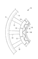
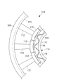
- FIG. 2 is a schematic diagram illustrating the configuration of the rotor disk and the stationary blades in the compression section of the gas turbine according to the present embodiment.
- the compressor 2 includes a stationary blade (turbine blade) 10 attached to the casing 6 of the gas turbine 1 and a disk-shaped rotor disk that is rotationally driven by the rotating shaft 5 (see FIG. 1). And a rotor blade disposed on a circumferential surface of the rotor (not shown).
- the stationary blades 10 and the moving blades are arranged at equal intervals in the circumferential direction of the rotating shaft 5 and are arranged alternately in the axial direction of the rotating shaft 5.
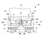
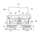
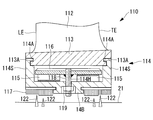
- FIG. 3 is a cross-sectional view illustrating the configuration in the vicinity of the seal holder in the stationary blade of FIG. 2 and 3, the stationary blade 10 includes an outer shroud portion 11, an airfoil portion 12, an inner shroud portion (shroud portion) 13, a seal holder (end housing) 14, and a spring ( An elastic portion 15, a spacer (pressing portion) 16, and a honeycomb seal 17 are provided.
- the outer shroud portion 11 is a member that constitutes a part of the wall surface of the flow path through which the fluid flows in the compression portion 2. Further, the outer shroud portion 11 is a curved plate-like member disposed at the radially outer end of the airfoil portion 12, and one outer shroud portion 11 is disposed for the plurality of airfoil portions 12. ing. In other words, the outer shroud part 11 is obtained by dividing a cylindrical member into a plurality of parts, and a plurality of airfoil parts 12 are connected to the inner peripheral surface thereof. As a shape of the outer shroud portion 11 and a connection method with the airfoil portion 12, a known shape and method can be used and are not particularly limited.
- the airfoil portion 12 is a member in which a cross section extending in the radial direction of the rotary shaft 5 is formed in a wing shape, and together with a moving blade rotated by the rotary shaft 5, a fluid such as air Is compressed and fed toward the combustion unit 3.
- the airfoil 12 includes a leading edge LE that is an upstream end in a flow of surrounding fluid, a trailing edge TE that is a downstream end, a suction surface that is a convex curved surface, and a concave curved shape. And a positive pressure surface.
- the inner shroud portion 13 constitutes a part of the flow path through which the fluid flows inside the compression portion 2, similarly to the outer shroud portion 11. Further, the inner shroud portion 13 is a curved plate-like member disposed at the radially inner end of the airfoil portion 12, and one inner shroud portion 13 is disposed with respect to one airfoil portion 12. Yes. In other words, the inner shroud portion 13 is obtained by dividing a cylindrical member into a plurality of parts, and the airfoil portion 12 is connected to the outer peripheral surface thereof.
- a fitting groove 13 ⁇ / b> A that extends in the circumferential direction (perpendicular to the paper surface of FIG. 3) and fits with the seal holder 14 is provided at the end of the inner shroud 13 on the front edge LE and rear edge TE side. Yes.
- the seal holder 14 is attached to the inner peripheral side (lower side in FIG. 3) of the inner shroud portion 13, and forms a space for accommodating the spring 15 and the spacer 16 together with the inner shroud portion 13.
- the seal holder 14 is provided with one seal holder 14 for the plurality of airfoil portions 12 and the inner shroud portion 13.
- the seal holder 14 is provided with a pair of side wall portions 14S extending along the radial direction on the front edge LE side and the rear edge TE side, and a bottom plate portion 14B connecting the radially inner ends of the pair of side wall portions 14S. It has been. In other words, the seal holder 14 is formed with a groove that opens toward the outer circumferential side (the upper side in FIG. 3).
- a protruding portion 14A that protrudes toward the inner side of the seal holder 14 and extends in the circumferential direction and fits with the fitting groove 13A of the inner shroud portion 13 is provided at the radially outer end of the side wall portion 14S. .
- the bottom plate portion 14 ⁇ / b> B is provided with a through hole 14 ⁇ / b> H through which a compression bolt (compression portion) 18 that presses the spring 15 together with the spacer 16 is inserted.
- the through holes 14H are provided at positions equally spaced from each of the pair of side wall portions 14S in the bottom plate portion 14B, and a plurality of through holes 14H are provided at predetermined intervals in the circumferential direction (perpendicular to the paper surface of FIG. 3). .
- the spring 15 is an elastic member that urges the inner shroud portion 13, the spacer 16, and the seal holder 14 in a separating direction. Furthermore, the spring 15 is configured to attenuate the vibration of the stationary blade 10, that is, the airfoil portion 12 and the inner shroud portion 13 by sliding with the inner shroud portion 13.
- the spring 15 is a plate spring that is formed in a substantially rectangular shape and is formed into a substantially wave shape.
- the spring force of the spring 15 is adjusted by adjusting the plate thickness of the plate spring.
- a material constituting the spring 15 a material that can maintain a required spring characteristic during operation of the gas turbine 1, that is, even when the spring 15 reaches a high temperature is desirable.
- the spring 15 is disposed in a space formed by the inner shroud portion 13 and the seal holder 14, more specifically, between the inner shroud portion 13 and the spacer 16. Furthermore, two springs 15 in total, one on the front edge LE side and one on the rear edge TE side, are arranged in parallel.
- FIG. 4 is a schematic diagram for explaining another arrangement example of the spring.
- the two springs 15 may be arranged in the same phase as described above, or may be arranged in different phases as shown in FIG. 4, and are not particularly limited.
- the top of one spring 15 is in contact with the inner shroud portion 13, and the top of the other spring 15 is in contact with the spacer 16.
- the shape of the spring 15 is such that the amplitude of the waveform (distance from the top to the top in the radial direction) is longer than the distance from the inner peripheral surface of the inner shroud portion 13 to the outer peripheral surface of the spacer 16, and each inner shroud portion.
- the top of the spring 15 is in contact with the 13 inner peripheral surfaces.
- the amplitude in the waveform of the spring 15 is determined based on the frictional force that attenuates the vibration of the stationary blade 10, that is, the amount of compression of the spring 15 necessary to generate the spring force.
- the wavelength (distance from the top to the top in the circumferential direction) in the waveform of the spring 15 is determined based on the arrangement interval, that is, the pitch of the inner shroud portion 13.
- the spacer 16 presses the spring 15 together with the compression bolt 18 toward the inner shroud portion 13, and is disposed between the bottom plate portion 14 ⁇ / b> B of the seal holder 14 and the spring 15. Is.
- one spacer 16 is disposed for the plurality of airfoils 12 and the inner shroud portion 13.
- the spacer 16 is obtained by dividing a cylindrical member into a plurality of parts, and is in contact with the spring 15 on the inner peripheral surface thereof.
- the spacer 16 is provided with an insertion hole 16H through which the compression bolt 18 is inserted.
- the honeycomb seal 17 together with seal fins 22 provided on the rotor 21, suppresses leakage of fluid flowing between the stationary blade 10 and the rotor 21.
- a known seal can be used as the honeycomb seal 17 and is not particularly limited.
- FIG. 5 is a schematic diagram for explaining a state when the seal holder is attached to or removed from the stationary blade of FIG. 3.
- the spring 15 and the spacer 16 are disposed on the inner peripheral surface side of the inner shroud portion 13, and the compression bolt 18 is screwed into the inner shroud portion 13 through the insertion hole 16 ⁇ / b> H of the spacer 16.
- the compression bolt 18 is further screwed into the inner shroud portion 13 to bring the spacer 16 closer to the inner shroud portion 13 and compress the spring 15.
- the distance from the inner peripheral surface of the inner shroud portion 13 to the outer peripheral surface of the spacer 16 is made shorter than the distance from the inner peripheral surface of the inner shroud portion 13 to the outer peripheral surface of the bottom plate portion 14B of the seal holder 14.
- the seal holder 14 is fitted to the inner shroud portion 13. Specifically, the protruding portion 14 ⁇ / b> A of the seal holder 14 is fitted into the fitting groove 13 ⁇ / b> A in the inner shroud portion 13. At this time, the seal holder 14 is fitted to the inner shroud portion 13 while sliding in the circumferential direction.
- FIG. 6 is a schematic diagram for explaining a state after the seal holder is attached to the stationary blade of FIG. Then, as shown in FIG. 6, the compression bolt 18 is removed from the inner shroud portion 13 through the through hole 14 ⁇ / b> H of the seal holder 14, and the attachment of the seal holder 14 is completed. The removal of the seal holder 14 is performed by performing the above steps in reverse order.
- the compression bolt 18 may be completely removed from the stationary blade 10 as described above, or may be left on the stationary blade 10 with a predetermined compression amount applied to the spring 15. is not.
- the stationary blade 10 vibrates due to the influence of the fluid flowing through the compression unit 2. Specifically, a vibration is generated in which the airfoil portion 12 and the inner shroud portion 13 of the stationary blade 10 swing in the circumferential direction.
- the vibration energy of the airfoil portion 12 and the inner shroud portion 13 is converted into friction energy such as heat energy by the above-described sliding, and the vibration in the stationary blade 10 is attenuated.
- the airfoil portion 12 and the inner shroud portion 13 vibrate and slide relative to the seal holder 14, the spring 15 that has pressed the inner shroud portion 13 away from the seal holder 14;
- the inner shroud portion 13 is relatively moved, that is, the spring 15 and the inner shroud portion 13 slide. Therefore, the energy related to the vibration of the airfoil portion 12 and the inner shroud portion 13 is converted into thermal energy (friction energy) by sliding, and the vibration of the airfoil portion 12 and the inner shroud portion 13 can be attenuated.
- the compression amount of the spring 15 is adjusted by bringing the spacer 16 closer to the inner shroud portion 13, the force with which the spring 15 presses the inner shroud portion 13 is adjusted. That is, since the frictional force between the spring 15 and the inner shroud portion 13 is adjusted, the amount of vibration attenuation in the airfoil portion 12 and the inner shroud portion 13 can be adjusted.
- the spring 15 can be easily exchanged by sliding the spring 15 together with the seal holder 14 from the inner shroud portion 13 and removing it. Therefore, even if the spring 15 is worn away due to wear due to long-term use, the spring 15 can be easily replaced. Further, since the spring 15 is disposed in a space surrounded by the seal holder 14 and the inner shroud portion 13, even if the spring 15 is broken, it jumps out of the space and damages the airfoil portion 12. Can be prevented.
- the spacer 16 approach the inner shroud portion 13
- the urging force by the spring 15 is received by the inner shroud portion 13 and the spacer 16.
- the biasing force of the spring 15 does not act on the seal holder 14. Therefore, when the seal holder 14 is slid with respect to the inner shroud portion 13 or when the seal holder 14 is attached or detached, the sliding force is reduced by reducing the frictional force acting on the contact surface between the inner shroud portion 13 and the seal holder 14. It can be easily moved and detached.
- the inner shroud portion 13 is independently arranged on each of the plurality of airfoil portions 12, compared to the case where the plurality of inner shroud portions 13 are integrally formed, each of the airfoil portions 12 and the inner airfoil portions 13 are arranged.
- the shroud portion 13 is easy to move relative to the spring 15. In other words, the sliding distance between the inner shroud portion 13 and the spring 15 is increased. Therefore, more energy related to the vibration of the airfoil portion 12 and the inner shroud portion 13 is converted into thermal energy (friction energy) due to sliding, and the vibration of the airfoil portion 12 and the inner shroud portion 13 is more easily damped. .
- the seal holder 14 is provided for the plurality of airfoil parts 12 and the inner shroud part 13 the seal holder 14 is disposed for each of the plurality of airfoil parts 12 and the inner shroud part 13. Compared with the case where it does, the sealing performance which concerns on the upstream and downstream of the stationary blade 10 can be made high.
- the spring 15 By making the spring 15 into a plate-like spring formed in a wave shape, a larger pressing force can be applied to the inner shroud portion 13 as compared with the case where other springs are used.
- a plurality of inner shroud portions 13 can be slid with respect to one spring 15 by bringing each top portion of the spring 15 into contact with the inner shroud portion 13.
- the spacer 16 can be brought close to the inner shroud portion 13 by the compression bolt 18. Therefore, the compression amount of the spring 15 is adjusted, and the force with which the spring 15 presses the inner shroud portion 13 is adjusted. That is, since the frictional force between the spring 15 and the inner shroud portion 13 is adjusted, the amount of vibration attenuation in the airfoil portion 12 and the inner shroud portion 13 can be adjusted.
- the biasing force by the spring 15 is received by the inner shroud portion 13 and the spacer 16 by making the spacer 16 approach the inner shroud portion 13. Therefore, when the seal holder 14 is slid with respect to the inner shroud portion 13 or when the seal holder 14 is attached or detached, the sliding force is reduced by reducing the frictional force acting on the contact surface between the inner shroud portion 13 and the seal holder 14. It can be easily moved and detached.
- FIG. 7 is a schematic diagram illustrating still another example of arrangement of the springs of FIG. It should be noted that two springs 15 may be disposed between the inner shroud portion 13 and the spacer 16 as in the above-described embodiment, and the four springs 15 are connected to the inner shroud portion 13 as shown in FIG. You may arrange
- the compression bolt 18 may be screwed into the inner shroud portion 13 and the spacer 16 may be pressed toward the inner shroud portion 13, or the pressing spring 15 may be screwed into the seal holder 14.
- the spacer 16 may be pressed toward the inner shroud portion 13 by pressing the tip of the pressing spring 15 against the spacer 16, and there is no particular limitation.
- the gas turbine 1 may be operated with the spacer 16 left between the seal holder 14 and the inner shroud portion 13, or the spacer 16 may be operated with the seal holder 14 and the inner shroud portion 13.
- the operation of the gas turbine 1 may be performed by removing from between the two, and is not particularly limited.
- the compression amount of the spring 15 may be adjusted by the compression bolt 18 to adjust the spring force by the spring 15, or the compression bolt 18 may be adjusted by adjusting only the plate thickness of the spacer 16.
- the spring force by the spring 15 may be adjusted even in a state in which is removed, and is not particularly limited.
- FIG. 8 is a schematic diagram illustrating the configuration of the rotor disk and the stationary blade in the compression section of the gas turbine according to the present embodiment.
- the compression unit 2 includes a stationary blade (turbine blade) 110 attached to the casing 6 of the gas turbine 1 and a disk-shaped rotor disk that is rotationally driven by the rotating shaft 5 (see FIG. 1).
- the stationary blades 110 and the moving blades are arranged at equal intervals in the circumferential direction of the rotating shaft 5 and are arranged alternately in the axial direction of the rotating shaft 5.
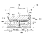
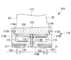
- FIG. 9 is a cross-sectional view illustrating the configuration in the vicinity of the seal holder in the stationary blade of FIG.
- the stationary blade 110 includes an outer shroud portion 111, an airfoil portion 112, an inner shroud portion (shroud portion) 113, a seal holder (end housing) 114, a spring ( An elastic portion 115, a damping plate (friction portion) 116, and a honeycomb seal 117 are provided.
- the outer shroud portion 111 is a member that constitutes a part of the wall surface of the flow path through which the fluid flows in the compression portion 2. Further, the outer shroud portion 111 is a curved plate-like member disposed at the radially outer end of the airfoil portion 112, and one outer shroud portion 111 is disposed for the plurality of airfoil portions 112. ing.
- the outer shroud part 111 is obtained by dividing a cylindrical member into a plurality of parts, and a plurality of airfoil parts 112 are connected to the inner peripheral surface thereof.
- a shape of the outer shroud portion 111 and a connection method with the airfoil portion 112 a known shape and method can be used, and there is no particular limitation.
- the airfoil portion 112 is a member in which a cross section extending in the radial direction of the rotary shaft 5 is formed in a wing shape, and together with a moving blade rotated by the rotary shaft 5, a fluid such as air Is compressed and fed toward the combustion unit 3.
- the airfoil 112 includes a leading edge LE that is an upstream end in the flow of the surrounding fluid, a trailing edge TE that is a downstream end, a suction surface that is a convexly curved surface, and a concavely curved shape. And a positive pressure surface.
- the inner shroud portion 113 constitutes a part of the flow path through which the fluid flows inside the compression portion 2, similarly to the outer shroud portion 111. Further, the inner shroud portion 113 is a curved plate-like member disposed at the radially inner end of the airfoil portion 112, and one inner shroud portion 113 is disposed with respect to one airfoil portion 112. Yes. In other words, the inner shroud portion 113 is obtained by dividing a cylindrical member into a plurality of parts, and the airfoil portion 112 is connected to the outer peripheral surface thereof.
- a fitting groove 113 ⁇ / b> A that extends in the circumferential direction (perpendicular to the paper surface of FIG. 9) and fits with the seal holder 114 is provided at the end of the inner shroud 113 on the front edge LE and rear edge TE sides. Yes.
- the seal holder 114 is attached to the inner peripheral side of the inner shroud portion 113 (lower side in FIG. 9), and forms a space for accommodating the spring 115 and the damping plate 116 together with the inner shroud portion 113. And a member that supports the honeycomb seal 117. Similar to the outer shroud portion 111, the seal holder 114 has one seal holder 114 for the plurality of airfoil portions 112 and the inner shroud portion 113.
- the seal holder 114 is provided with a pair of side wall portions 114S extending along the radial direction on the front edge LE side and the rear edge TE side, and a bottom plate portion 114B connecting the radially inner ends of the pair of side wall portions 114S. It has been. In other words, the seal holder 114 is formed with a groove that opens toward the outer circumferential side (the upper side in FIG. 9).
- a protruding portion 114A that protrudes toward the inner side of the seal holder 114 and extends in the circumferential direction and fits with the fitting groove 113A of the inner shroud portion 113 is provided at the radially outer end of the side wall portion 114S. .
- the bottom plate portion 114B is provided with a through hole 114H through which a compression bolt (compression portion) 118 that presses the spring 115 together with the damping plate 116 is inserted.
- the through holes 114H are provided at positions equally spaced from each of the pair of side wall portions 114S in the bottom plate portion 114B, and a plurality of through holes 114H are provided at a predetermined interval in the circumferential direction (perpendicular to the paper surface of FIG. 9). .
- the spring 115 is an elastic member that urges the inner shroud portion 113, the damping plate 116, and the seal holder 114 in the direction of separating. Furthermore, the spring 115 dampens vibrations of the stationary blade 110, that is, the airfoil portion 112 and the inner shroud portion 113 together with the damping plate 116.
- the spring 115 is a plate spring formed in a substantially rectangular shape and formed in a substantially wave shape, and the spring force of the spring 115 is adjusted by adjusting the plate thickness of the plate spring.
- the material constituting the spring 115 is preferably a material that can maintain the required spring characteristics during operation of the gas turbine 1, that is, even when the spring 115 is at a high temperature.
- the spring 115 is disposed in a space formed by the inner shroud portion 113 and the seal holder 114, more specifically, between the damping plate 116 and the seal holder 114. Further, a total of two springs 115 are arranged in parallel, one on the front edge LE side and one on the rear edge TE side.
- FIG. 10 is a schematic diagram for explaining another arrangement example of the springs of FIG. Note that the two springs 115 may be arranged in the same phase as described above, or may be arranged in different phases as shown in FIG. 10, and are not particularly limited. In the arrangement of the spring 115 shown in FIG. 10, the top of one spring 115 is in contact with the damping plate 116, and the top of the other spring 115 is in contact with the seal holder 114.
- the spring 115 is applied to all the damping plates 116. Can be touched. That is, the springs 115 can be brought into contact with all the damping plates 116 by bringing the tops of the other springs 115 into contact with the damping plate 116 that does not come into contact with the top of one spring 115. .
- the shape of the spring 115 is such that the amplitude of the waveform (distance from the top to the top in the radial direction) is longer than the distance from the outer peripheral surface of the damping plate 116 to the inner peripheral surface of the seal holder 114, and each damping plate 116. It is determined that the top of the spring 115 abuts against the inner peripheral surface of the spring.
- the amplitude in the waveform of the spring 115 is determined based on the frictional force that attenuates the vibration of the stationary blade 110, that is, the amount of compression of the spring 115 necessary to generate the spring force.
- the wavelength (distance from the top to the top in the circumferential direction) in the waveform of the spring 115 is determined based on the arrangement interval, that is, the pitch of the inner shroud portion 113 and the damping plate 116.
- the damping plate 116 is pressed against the inner peripheral surface of the inner shroud portion 113 by the spring 15 and is disposed between the inner shroud portion 113 and the spring 115. Similarly to the inner shroud portion 113, one damping plate 116 is disposed for each of the plurality of airfoil portions 112 and the inner shroud portion 113.
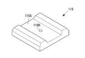
- FIG. 11 is a schematic diagram illustrating the configuration of the damping plate of FIG.
- the damping plate 116 is provided with a bolt hole 116H into which the compression bolt 118 is screwed and a relief groove 116G formed on a surface facing the inner shroud portion 113.
- the bolt hole 116 ⁇ / b> H is a female screw hole formed substantially at the center of the damping plate 116, and the compression bolt 118 is screwed into the bolt hole 116 ⁇ / b> H.
- One end of the compression bolt 118 is screwed into the bolt hole 116H of the damping plate 116.
- the other end of the compression bolt 118 is inserted into the through hole 114H of the seal holder 114.
- a nut (compression portion) 119 for compressing the spring 115 is screwed together with the compression bolt 118 to the other end portion of the compression bolt 118.
- the escape groove 116 ⁇ / b> G is a groove formed on a surface (an upper surface in FIGS. 9 and 11) facing the inner shroud portion 113 in the damping plate 116.
- the relief groove 116G is a groove extending along the direction in which the rotating shaft 5 extends (direction perpendicular to the paper surface of FIG. 9), in other words, in the direction in which the damping plate 116 and the inner shroud portion 113 slide.
- the grooves extend in a direction intersecting each other, more preferably in a direction orthogonal to each other.
- the surface of the damping plate 116 that contacts the inner shroud portion 113 is divided into two with the escape groove 116G interposed therebetween, and each surface contacts the inner shroud portion 113. For this reason, even if the inner shroud portion 113 and the damping plate 116 slide, the inner shroud portion 113 and the damping plate 116 stably come into contact with each other on the two surfaces described above, and the occurrence of defects such as one-side contact is prevented.
- the honeycomb seal 117 suppresses leakage of fluid flowing between the stationary blade 110 and the rotor 21 together with the seal fins 122 provided on the rotor 21.
- a known seal can be used as the honeycomb seal 117, and is not particularly limited.
- FIG. 12 is a schematic diagram for explaining a state when the seal holder is attached to or removed from the stationary blade of FIG. 9.
- the spring 115 and the damping plate 116 are disposed inside the seal holder 114, and the other end of the compression bolt 118 is inserted into the through hole 114 ⁇ / b> H of the seal holder 114.
- a nut 119 is screwed into the other end of the compression bolt 118 to bring the damping plate 116 closer to the bottom plate portion 114B of the seal holder 114, thereby compressing the spring 115.
- the distance from the outer peripheral surface of the bottom plate portion 114B to the outer peripheral surface of the damping plate 116 is made shorter than the distance from the outer peripheral surface of the bottom plate portion 114B to the inner peripheral surface of the inner shroud portion 113.
- the seal holder 114 is fitted into the inner shroud portion 113. Specifically, the protrusion 114 ⁇ / b> A of the seal holder 114 is fitted into the fitting groove 113 ⁇ / b> A in the inner shroud portion 113. At this time, the seal holder 114 is fitted to the inner shroud portion 113 while sliding in the circumferential direction.
- FIG. 13 is a schematic diagram for explaining a state after the seal holder is attached to the stationary blade of FIG. 9. Then, as shown in FIG. 13, the nut 119 is removed from the compression bolt 118, and the damping plate 116 is brought into contact with the inner shroud portion 113 to complete the attachment of the seal holder 114. The removal of the seal holder 114 is performed by performing the above steps in reverse order.
- the compression bolt 118 may remain attached to the damping plate 116 as described above, or may be detached from the damping plate 116, and is not particularly limited.
- the stationary blade 110 is vibrated by the influence of the fluid flowing through the compression unit 2. Specifically, a vibration is generated in which the airfoil portion 112 and the inner shroud portion 113 of the stationary blade 110 swing in the circumferential direction.
- the vibration energy of the airfoil portion 112 and the inner shroud portion 113 is converted into friction energy such as heat energy by the above-described sliding, and the vibration in the stationary blade 110 is attenuated.
- the urging force by the spring 115 is received by the damping plate 116 and the seal holder 114 by bringing the damping plate 116 closer to the seal holder 114.
- the biasing force of the spring 115 does not act on the inner shroud portion 113. Therefore, when the seal holder 114 is slid with respect to the inner shroud portion 113 or when the seal holder 114 is attached or detached, the sliding force is reduced by reducing the frictional force acting on the contact surface between the inner shroud portion 113 and the seal holder 114. It can be easily moved and detached.
- the spring 115 can be easily exchanged by sliding the spring 115 together with the seal holder 114 from the inner shroud portion 113 to be attached and detached. Therefore, even if the spring 115 is worn away due to wear due to long-term use, the spring 115 can be easily replaced. Further, since the spring 115 is disposed in a space surrounded by the seal holder 114 and the inner shroud portion 113, even if the spring 115 is broken, it jumps out of the space and damages the airfoil portion 112. Can be prevented.
- the inner shroud portion 113 is independently arranged on each of the plurality of airfoil portions 112, each of the airfoil portions 112 and the inner side is compared with the case where the plurality of inner shroud portions 113 are integrally formed.
- the shroud portion 113 is easy to move relative to the damping plate 116. In other words, the sliding distance between the inner shroud portion 113 and the damping plate 116 becomes longer. Therefore, more energy related to the vibration of the airfoil portion 112 and the inner shroud portion 113 is converted into thermal energy (friction energy) due to sliding, and the vibration of the airfoil portion 112 and the inner shroud portion 113 is more easily damped. .
- the seal holder 114 is provided for the plurality of airfoil portions 112 and the inner shroud portion 113, the seal holder 114 is disposed for each of the plurality of airfoil portions 112 and the inner shroud portion 113. Compared to the case, the sealing performance between the upstream side and the downstream side of the stationary blade 110 is enhanced.
- the spring 115 as a spring having a wave shape, it is possible to apply a larger pressing force to the inner shroud portion 113 as compared to the case of using another spring.
- the plurality of damping plates 116 are pressed against the inner shroud portion 113 by one spring.
- the compression bolt 118 protrudes from the damping plate 116 through the seal holder 114, the compression bolt 118 and the damping plate 116 can move in the direction of approaching and separating from the seal holder 114, and the approaching and separating of the compression bolt 118 and the damping plate 116. Movement in the direction intersecting the direction, that is, the circumferential direction of the rotating shaft 5 is restricted. Therefore, the inner shroud portion 113 and the damping plate 116 can be reliably slid.
- FIG. 14 is a schematic diagram illustrating still another example of arrangement of the springs of FIG. Note that, as in the above-described embodiment, two springs 115 may be disposed between the damping plate 116 and the seal holder 114, and as shown in FIG. 14, the four springs 115 are sealed with the damping plate 116 and the seal. It may be arranged between the holder 114 and the number of springs 115 is not particularly limited.
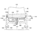
- FIG. 15 is a schematic diagram for explaining another configuration of the seal holder of FIG. 9.
- the honeycomb seal 117 may be disposed on the seal holder 114 and the seal fins 122 may be disposed on the rotor 21 as in the above-described embodiment, or the seal fins 122 may be disposed on the seal holder 114 as illustrated in FIG. It is good also as a labyrinth seal which arrange
- the compression amount of the spring 115 may be adjusted by the compression bolt 118 and the nut 119, and the spring force by the spring 115 may be adjusted, or only the plate thickness of the damping plate 116 may be adjusted. Even when the nut 119 is removed, the spring force by the spring 115 may be adjusted, and is not particularly limited.
- a gas turbine according to a third embodiment of the present invention will be described with reference to FIGS. 1 and 16 to 19.
- the turbine blade of the present invention will be described by applying it from the first-stage stationary blade to the third-stage stationary blade in the compression section 2 of the gas turbine 1, the 5-stage stationary blade to the 17-stage stationary blade, or the 10-stage stationary blade to the 14-stage stationary blade.
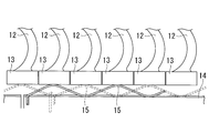
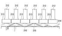
- FIG. 16 is a schematic diagram illustrating the configuration of the rotor disk and the stationary blades in the compression section of the gas turbine according to the present embodiment.
- the compression unit 2 includes a stationary blade (turbine blade) 210 attached to the casing 6 of the gas turbine 1 and a disk-shaped rotor disk that is driven to rotate by the rotating shaft 5 (see FIG. 1 and FIG. 16). And a rotor blade disposed on a circumferential surface of the rotor (not shown).
- the stationary blades 210 and the moving blades are arranged side by side at equal intervals in the circumferential direction of the rotating shaft 5 and are arranged alternately in the axial direction of the rotating shaft 5.
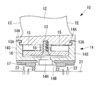
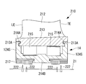
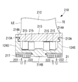
- FIG. 17 is a cross-sectional view illustrating the configuration in the vicinity of the seal holder in the stationary blade of FIG.
- the stationary blade 210 includes an outer shroud portion 211, an airfoil portion 212, an inner shroud portion (shroud portion) 213, a seal holder (end housing) 214, a spring ( An elastic portion) 215 and a honeycomb seal 217 are provided.
- the outer shroud portion 211 is a member that constitutes a part of the wall surface of the flow path through which the fluid flows in the compression portion 2. Further, the outer shroud portion 211 is a curved plate-like member disposed at the radially outer end of the airfoil portion 212, and one outer shroud portion 211 is disposed for the plurality of airfoil portions 212. ing. In other words, the outer shroud part 211 is obtained by dividing a cylindrical member into a plurality of parts, and a plurality of airfoil parts 212 are connected to the inner peripheral surface thereof. As a shape of the outer shroud portion 211 and a connection method with the airfoil portion 212, a known shape and method can be used, and there is no particular limitation.
- the airfoil portion 212 is a member in which a cross section extending in the radial direction of the rotary shaft 5 is formed in a wing shape, and is a fluid such as air together with a moving blade rotated by the rotary shaft 5. Is compressed and fed toward the combustion unit 3.
- the airfoil 212 includes a leading edge LE that is an upstream end in a flow of surrounding fluid, a trailing edge TE that is a downstream end, a suction surface that is a convex curved surface, and a concave curved shape. And a positive pressure surface.
- the inner shroud portion 213 constitutes a part of the flow path through which the fluid flows inside the compression portion 2, similarly to the outer shroud portion 211. Further, the inner shroud portion 213 is a curved plate-like member disposed at the radially inner end of the airfoil portion 212, and one inner shroud portion 213 is disposed with respect to one airfoil portion 212. Yes. In other words, the inner shroud part 213 is obtained by dividing a cylindrical member into a plurality of parts, and the airfoil part 212 is connected to the outer peripheral surface thereof.
- a fitting groove 213 ⁇ / b> A that extends in the circumferential direction (perpendicular to the paper surface of FIG. 17) and fits with the seal holder 214 is provided at the end of the inner shroud 213 on the front edge LE and rear edge TE sides. Yes.
- the seal holder 214 is attached to the inner peripheral side (the lower side of FIG. 17) of the inner shroud portion 213, and forms a space for accommodating the spring 215 in the inner shroud portion 213 together with the inner shroud portion 213.
- the seal holder 214 Similar to the outer shroud portion 211, the seal holder 214 has one seal holder 214 for the plurality of airfoil portions 212 and the inner shroud portion 213.
- the seal holder 214 is provided with a pair of side wall portions 214S extending along the radial direction on the front edge LE side and the rear edge TE side, and a bottom plate portion 214B connecting the radially inner ends of the pair of side wall portions 214S. It has been. In other words, the seal holder 214 is formed with a groove that opens toward the outer circumferential side (upper side in FIG. 17).
- a protruding portion 214A that protrudes toward the inner side of the seal holder 214 and extends in the circumferential direction and fits with the fitting groove 213A of the inner shroud portion 213 is provided at the radially outer end of the side wall portion 214S. .
- the spring 215 is an elastic member that urges the inner shroud portion 213 and the seal holder 214 in a direction away from each other. Further, the spring 215 damps the vibration of the stationary blade 210, that is, the airfoil portion 212 and the inner shroud portion 213 by sliding with the inner shroud portion 213.
- the spring 215 biases the inner shroud portion 213 and the seal holder 214 away from each other, whereby the fitting groove 213A and the protruding portion 214A are pressed and brought into close contact with each other.
- the sealing property between the two can be ensured.
- the spring 215 is a plate spring formed in a substantially rectangular shape, and is formed in a substantially waveform, and the spring force of the spring 215 is adjusted by adjusting the plate thickness of the plate spring.
- the material constituting the spring 215 is preferably a material that can maintain the required spring characteristics during operation of the gas turbine 1, that is, even when the spring 215 is at a high temperature.
- the spring 215 is disposed in a space formed by the inner shroud portion 213 and the seal holder 214, more specifically, between the inner shroud portion 213 and the seal holder 214. Further, a total of two springs 215 are arranged in parallel, one on the front edge LE side and one on the rear edge TE side.
- This embodiment is applied to an example in which the two springs 215 are arranged in the same phase, in other words, an example in which the tops of the two springs 215 are in contact with the inner shroud part 213 and the seal holder 214 at the same position. To do.
- FIG. 18 is a schematic diagram for explaining another arrangement example of the springs of FIG. Note that the two springs 215 may be arranged in the same phase as described above, or may be arranged in different phases as shown in FIG. 18, and there is no particular limitation. In the arrangement of the spring 215 shown in FIG. 18, the top of one spring 215 is in contact with the inner shroud 213, and the top of the other spring 215 is in contact with the seal holder 214.
- the shape of the spring 215 is such that the amplitude of the waveform (distance from the top to the top in the radial direction) is longer than the distance from the inner peripheral surface of the inner shroud portion 213 to the outer peripheral surface of the seal holder 214, and each inner shroud It is determined so that the top of the spring 215 abuts against the inner peripheral surface of the portion 213.
- the amplitude in the waveform of the spring 215 is determined based on the frictional force that attenuates the vibration of the stationary blade 210, that is, the amount of compression of the spring 215 necessary to generate the spring force.
- the wavelength (distance from the top to the top in the circumferential direction) in the waveform of the spring 215 is determined based on the arrangement interval, that is, the pitch of the inner shroud portions 213.
- the honeycomb seal 217 suppresses leakage of the fluid flowing between the stationary blade 210 and the rotor 21 together with the seal fins 222 provided on the rotor 21.
- a known seal can be used, and is not particularly limited.
- the stationary blade 210 vibrates due to the influence of the fluid flowing through the compression unit 2. Specifically, a vibration is generated in which the airfoil portion 212 and the inner shroud portion 213 of the stationary blade 210 swing in the circumferential direction.
- the vibration energy of the airfoil portion 212 and the inner shroud portion 213 is converted into friction energy such as heat energy by the above-described sliding, and the vibration in the stationary blade 210 is attenuated.
- the spring 215 and the inner shroud portion 213 move relative to each other, that is, the spring 215 and the inner shroud portion. 213 slides. Therefore, the energy related to the vibration of the airfoil portion 212 and the inner shroud portion 213 is converted into thermal energy (friction energy) by sliding, and the vibration of the airfoil portion 212 and the inner shroud portion 213 can be damped.
- the spring 215 can be easily replaced by sliding the spring 215 together with the seal holder 214 from the inner shroud portion 213 to be attached and detached. Therefore, even if the spring 215 is worn out due to wear due to long-term use, the spring 215 can be easily replaced. Further, since the spring 215 is disposed in a space surrounded by the seal holder 214 and the inner shroud portion 213, even if the spring 215 is broken, it jumps out of the space and damages the airfoil portion 212. Can be prevented.
- each of the airfoil portions 212 and the inner airfoil portions 213 is compared with the case where the plurality of inner shroud portions 213 are integrally formed.
- the shroud part 213 is easy to move relative to the spring 215. In other words, the sliding distance between the inner shroud portion 213 and the spring 215 is increased. Therefore, more energy related to the vibration of the airfoil portion 212 and the inner shroud portion 213 is converted into thermal energy (friction energy) due to sliding, and the vibration of the airfoil portion 212 and the inner shroud portion 213 is further damped. Can do.
- FIG. 19 is a schematic diagram illustrating still another example of arrangement of the springs of FIG. Note that, as in the above-described embodiment, two springs 215 may be disposed between the inner shroud portion 213 and the seal holder 214, and as shown in FIG. 19, the four springs 215 are arranged on the inner shroud portion 213. And the number of the springs 215 are not particularly limited.
- the turbine blade of the present invention has been described as applied to the stationary blade in the compression portion of the gas turbine.
- the turbine blade can also be applied to the stationary blade in the turbine portion of the gas turbine.
Landscapes
- Engineering & Computer Science (AREA)
- Mechanical Engineering (AREA)
- General Engineering & Computer Science (AREA)
- Turbine Rotor Nozzle Sealing (AREA)
- Structures Of Non-Positive Displacement Pumps (AREA)
Abstract
Description
翼形部とシュラウド部との間の固定は、シュラウド部に設けた差込口に翼形部から突出した差込部を差込むテノンタイプの固定方法や、上述の差込口に、翼形部から広がって形成された差込ツバ部を差し込むポークチョップタイプの固定方法が挙げられる。
また翼形部とシュラウド部とを一体構造として成型する場合や加工する場合もある。
このシール構造は、加工の容易さや補修の容易さを考慮して、翼形部またはシュラウド部と別構造として形成され、形成後に翼形部またはシュラウド部と組み合わせる構成であってもよい。
上述の励振力としては、回転する動翼の後流流れ(ウェーク)による励振力や、干渉流れ(ポテンシャル)による励振力などを例示することができる。
このため、翼形部やシュラウド部に対しては、振動応答が発生したとしても疲労亀裂を起こさない体格強度を持たせる設計が行われるとともに、静翼の固有振動数を、静翼に働くと予想される励振周波数からずらす、言い換えると離調させる必要がある。
このようにすることで、プロファイル部と連接されたシュラウド部が共振により振動変形すると、シュラウド部とバネとが摺動して、シュラウド部とバネとの間に摩擦力が働く。すると、シュラウド部とバネとの摺動面において振動エネルギが摩擦エネルギ(熱エネルギ)に変換され、静翼の振動が減衰される。
本発明の第1の態様に係るタービン翼は、翼形部の端部に配置されたシュラウド部と、前記シュラウド部に対してスライド移動可能であるとともに着脱可能とされ、前記シュラウド部との間に空間を形成する端部筐体と、前記空間に配置されシュラウド部と端部筐体とを離間させる方向に付勢するとともに、前記シュラウド部と相対移動可能に配置された弾性部と、が設けられていることを特徴とする。
そのため、より多くの翼形部およびシュラウド部の振動に係るエネルギが、摺動による熱エネルギ(摩擦エネルギ)に変換され、翼形部およびシュラウド部の振動がより減衰されやすい。
また、板バネの各頂部をそれぞれシュラウド部に当接させることにより、一つの板バネに対して複数のシュラウド部が摺動される。
また、バネの各頂部をそれぞれシュラウド部に当接させることにより、一つのバネに対して複数のシュラウド部が摺動される。
そのため、より多くの翼形部およびシュラウド部の振動に係るエネルギが、摺動による熱エネルギ(摩擦エネルギ)に変換され、翼形部およびシュラウド部の振動がより減衰されやすい。
その一方で、バネの各頂部をそれぞれシュラウド部に当接させることにより、一つのバネにより複数の摩擦部がシュラウド部に押し付けられる。
また、押圧部をシュラウド部に接近させることにより、弾性部による付勢力はシュラウド部および押圧部により受け止められるため、シュラウド部に対して端部筐体をスライド移動させる場合や、端部筐体を着脱させる場合に、シュラウド部と端部筐体との接触面に働く摩擦力を小さくして、組み付けや分解を容易にすることができるという効果を奏する。
また、弾性部を端部筐体とともにシュラウド部からスライド移動させて着脱させることにより、弾性部を容易に交換することができるという効果を奏する。
また、摩擦部を端部筐体に接近させることにより、弾性部による付勢力は摩擦部および端部筐体により受け止められるため、シュラウド部に対して端部筐体をスライド移動させる場合や、端部筐体を着脱させる場合に、シュラウド部と端部筐体との接触面に働く摩擦力を小さくして、スライド移動や着脱を容易にすることができるという効果を奏する。
ガスタービン1には、図1に示すように、圧縮部2と、燃焼部3と、タービン部4と、回転軸5と、が設けられている。
なお、圧縮部2としては、公知の構成を用いることができ、特に限定するものではない。
なお、燃焼部3としては、公知のものを用いることができ、特に限定するものではない。
なお、タービン部4としては、公知の構成を用いることができ、特に限定するものではない。
本発明の第1実施形態に係るガスタービンについて、図1から図7を参照して説明する。なお、本実施形態では、本願発明のタービン翼をガスタービン1の圧縮部2における6段静翼から9段静翼に適用して説明する。
圧縮部2には、図1および図2に示すように、ガスタービン1のケーシング6に取り付けられる静翼(タービン翼)10と、回転軸5により回転駆動される円板状のロータディスク(図示せず)の円周面に配置される動翼と、が設けられている。
静翼10と動翼とは、回転軸5における周方向に等間隔に並んで配置されているとともに、回転軸5の軸線方向に交互に並んで配置されている。
図3は、図2の静翼におけるシールホルダ近傍の構成を説明する断面図である。
静翼10は、図2および図3に示すように、外側シュラウド部11と、翼形部12と、内側シュラウド部(シュラウド部)13と、シールホルダ(端部筐体)14と、バネ(弾性部)15と、スペーサ(押圧部)16と、ハニカムシール17と、が設けられている。
外側シュラウド部11の形状や、翼形部12との接続方法としては、公知の形状や方法を用いることができ、特に限定するものではない。
翼形部12には、周囲の流体の流れにおける上流側端部である前縁LEと、下流側端部である後縁TEと、凸状に湾曲した面である負圧面と、凹状に湾曲した面である正圧面とが設けられている。
シールホルダ14は、外側シュラウド部11と同様に、複数の翼形部12および内側シュラウド部13に対して一つのシールホルダ14が配置されている。
言い換えると、シールホルダ14には、周方向外側(図3の上側)に向かって開口した溝部が形成されている。
なお、二つのバネ15を上述のように同じ位相で配置してもよいし、図4に示すように異なる位相で配置してもよく、特に限定するものではない。
図4に示すバネ15の配置では、一のバネ15の頂部が内側シュラウド部13に接触している場所で、他のバネ15の頂部はスペーサ16と接触している。
スペーサ16は、シールホルダ14と同様に、複数の翼形部12および内側シュラウド部13に対して一つのスペーサ16が配置されている。言い換えると、スペーサ16は、円筒状の部材を複数に分割したものであって、その内周面においてバネ15と接触するものである。
スペーサ16には、圧縮ボルト18が挿通される挿通孔16Hが設けられている。
ハニカムシール17としては公知のものを用いることができ、特に限定するものではない。
図5は、図3の静翼におけるシールホルダの取り付け時または取り外し時の状態を説明する模式図である。
まず、内側シュラウド部13における内周面側にバネ15およびスペーサ16を配置し、圧縮ボルト18をスペーサ16の挿通孔16Hを介して、内側シュラウド部13に螺合させる。そして、圧縮ボルト18をさらに内側シュラウド部13にねじ込むことにより、スペーサ16を内側シュラウド部13に接近させ、バネ15を圧縮する。
そして、図6に示すように、シールホルダ14の貫通孔14Hを介して、圧縮ボルト18を内側シュラウド部13から取り外してシールホルダ14の取り付けが完了する。
シールホルダ14の取り外しは、上述の工程を逆から順に行うことにより行われる。
ガスタービン1が運転されると、圧縮部2を流れる流体等の影響により静翼10に振動が生じる。具体的には、静翼10の翼形部12および内側シュラウド部13が周方向に振れる振動が発生する。
また、バネ15は、シールホルダ14および内側シュラウド部13により囲まれた空間内に配置されているため、たとえ、バネ15が破損しても当該空間から飛び出して翼形部12に損傷を与えることを防止することができる。
そのため、より多くの翼形部12および内側シュラウド部13の振動に係るエネルギが、摺動による熱エネルギ(摩擦エネルギ)に変換され、翼形部12および内側シュラウド部13の振動がより減衰されやすい。
その一方で、バネ15の各頂部をそれぞれ内側シュラウド部13に当接させることにより、一つのバネ15に対して複数の内側シュラウド部13を摺動させることができる。
なお、上述の実施形態のように、二つのバネ15を内側シュラウド部13とスペーサ16との間に配置してもよいし、図7に示すように、四つのバネ15を内側シュラウド部13とスペーサ16との間に配置してもよく、バネ15の数を特に限定するものではない。
本発明の第2実施形態に係るガスタービンについて、図1および図8から図15を参照して説明する。なお、本実施形態では、本願発明のタービン翼をガスタービン1の圧縮部2における1段静翼から4段静翼に適用して説明する。
図8は、本実施形態に係るガスタービンの圧縮部におけるロータディスクおよび静翼の構成を説明する模式図である。
圧縮部2には、図1および図8に示すように、ガスタービン1のケーシング6に取り付けられる静翼(タービン翼)110と、回転軸5により回転駆動される円板状のロータディスク(図示せず)の円周面に配置される動翼と、が設けられている。
静翼110と動翼とは、回転軸5における周方向に等間隔に並んで配置されているとともに、回転軸5の軸線方向に交互に並んで配置されている。
図9は、図8の静翼におけるシールホルダ近傍の構成を説明する断面図である。
静翼110は、図8および図9に示すように、外側シュラウド部111と、翼形部112と、内側シュラウド部(シュラウド部)113と、シールホルダ(端部筐体)114と、バネ(弾性部)115と、ダンピングプレート(摩擦部)116と、ハニカムシール117と、が設けられている。
外側シュラウド部111の形状や、翼形部112との接続方法としては、公知の形状や方法を用いることができ、特に限定するものではない。
翼形部112には、周囲の流体の流れにおける上流側端部である前縁LEと、下流側端部である後縁TEと、凸状に湾曲した面である負圧面と、凹状に湾曲した面である正圧面とが設けられている。
シールホルダ114は、外側シュラウド部111と同様に、複数の翼形部112および内側シュラウド部113に対して一つのシールホルダ114が配置されている。
言い換えると、シールホルダ114には、周方向外側(図9の上側)に向かって開口した溝部が形成されている。
なお、二つのバネ115を上述のように同じ位相で配置してもよいし、図10に示すように異なる位相で配置してもよく、特に限定するものではない。
図10に示すバネ115の配置では、一のバネ115の頂部がダンピングプレート116に接触している場所で、他のバネ115の頂部はシールホルダ114と接触している。
ダンピングプレート116は、内側シュラウド部113と同様に、複数の翼形部112および内側シュラウド部113のそれぞれに対して一つのダンピングプレート116が配置されている。
ダンピングプレート116には、圧縮ボルト118が螺合されるボルト孔116Hと、内側シュラウド部113と対向する面に形成された逃がし溝116Gと、が設けられている。
圧縮ボルト118における一方の端部がダンピングプレート116のボルト孔116Hに螺合されている。圧縮ボルト118における他方の端部は、シールホルダ114の貫通孔114Hに挿通されている。圧縮ボルト118の他方の端部には、圧縮ボルト118とともに、バネ115を圧縮するナット(圧縮部)119が螺合される。
ハニカムシール117としては公知のものを用いることができ、特に限定するものではない。
図12は、図9の静翼におけるシールホルダの取り付け時または取り外し時の状態を説明する模式図である。
まず、シールホルダ114における内部にバネ115およびダンピングプレート116を配置し、圧縮ボルト118の他方の端部をシールホルダ114の貫通孔114Hに挿通する。そして、圧縮ボルト118の他方の端部にナット119を螺合して、ダンピングプレート116をシールホルダ114の底板部114Bに接近させ、バネ115を圧縮する。
そして、図13に示すように、ナット119を圧縮ボルト118から取り外し、ダンピングプレート116を内側シュラウド部113に接触させることにより、シールホルダ114の取付けが完了する。
シールホルダ114の取り外しは、上述の工程を逆から順に行うことにより行われる。
ガスタービン1が運転されると、圧縮部2を流れる流体等の影響により静翼110に振動が生じる。具体的には、静翼110の翼形部112および内側シュラウド部113が周方向に振れる振動が発生する。
また、バネ115は、シールホルダ114および内側シュラウド部113により囲まれた空間内に配置されているため、たとえ、バネ115が破損しても当該空間から飛び出して翼形部112に損傷を与えることを防止することができる。
そのため、より多くの翼形部112および内側シュラウド部113の振動に係るエネルギが、摺動による熱エネルギ(摩擦エネルギ)に変換され、翼形部112および内側シュラウド部113の振動がより減衰されやすい。
その一方で、バネ115の各頂部をそれぞれダンピングプレート116に当接させることにより、一つのバネにより複数のダンピングプレート116が内側シュラウド部113に押し付けられる。
なお、上述の実施形態のように、二つのバネ115をダンピングプレート116とシールホルダ114との間に配置してもよいし、図14に示すように、四つのバネ115をダンピングプレート116とシールホルダ114との間に配置してもよく、バネ115の数を特に限定するものではない。
なお、上述の実施形態のように、シールホルダ114にハニカムシール117を配置し、ロータ21にシールフィン122を配置してもよいし、図15に示すように、シールホルダ114にシールフィン122を配置し、ロータ21のシールフィン122と対向する位置に段差を設けたラビリンスシールとしてもよく、特に限定するものではない。
この発明の第3実施形態に係るガスタービンについて、図1および図16から図19を参照して説明する。なお、本実施形態では、本願発明のタービン翼をガスタービン1の圧縮部2における1段静翼から3段静翼、5段静翼から17段静翼、あるいは、10段静翼から14段静翼に適用して説明する。
圧縮部2には、図1および図16に示すように、ガスタービン1のケーシング6に取り付けられる静翼(タービン翼)210と、回転軸5により回転駆動される円板状のロータディスク(図示せず)の円周面に配置される動翼と、が設けられている。
静翼210と動翼とは、回転軸5における周方向に等間隔に並んで配置されているとともに、回転軸5の軸線方向に交互に並んで配置されている。
図17は、図16の静翼におけるシールホルダ近傍の構成を説明する断面図である。
本実施形態では、静翼210をピッチが固定された静翼、言い換えると、圧縮部2の内部を流れる流体の流れに対して、迎え角が固定された静翼に適用して説明する。
静翼210は、図16および図17に示すように、外側シュラウド部211と、翼形部212と、内側シュラウド部(シュラウド部)213と、シールホルダ(端部筐体)214と、バネ(弾性部)215と、ハニカムシール217と、が設けられている。
外側シュラウド部211の形状や、翼形部212との接続方法としては、公知の形状や方法を用いることができ、特に限定するものではない。
翼形部212には、周囲の流体の流れにおける上流側端部である前縁LEと、下流側端部である後縁TEと、凸状に湾曲した面である負圧面と、凹状に湾曲した面である正圧面とが設けられている。
シールホルダ214は、外側シュラウド部211と同様に、複数の翼形部212および内側シュラウド部213に対して一つのシールホルダ214が配置されている。
言い換えると、シールホルダ214には、周方向外側(図17の上側)に向かって開口した溝部が形成されている。
なお、二つのバネ215を上述のように同じ位相で配置してもよいし、図18に示すように異なる位相で配置してもよく、特に限定するものではない。
図18に示すバネ215の配置では、一のバネ215の頂部が内側シュラウド部213に接触している場所で、他のバネ215の頂部はシールホルダ214と接触している。
ハニカムシール217としては公知のものを用いることができ、特に限定するものではない。
ガスタービン1が運転されると、圧縮部2を流れる流体等の影響により静翼210に振動が生じる。具体的には、静翼210の翼形部212および内側シュラウド部213が周方向に振れる振動が発生する。
また、バネ215は、シールホルダ214および内側シュラウド部213により囲まれた空間内に配置されているため、たとえ、バネ215が破損しても当該空間から飛び出して翼形部212に損傷を与えることを防止することができる。
そのため、より多くの翼形部212および内側シュラウド部213の振動に係るエネルギが、摺動による熱エネルギ(摩擦エネルギ)に変換され、翼形部212および内側シュラウド部213の振動をより減衰させることができる。
なお、上述の実施形態のように、二つのバネ215を内側シュラウド部213とシールホルダ214との間に配置してもよいし、図19に示すように、四つのバネ215を内側シュラウド部213とシールホルダ214との間に配置してもよく、バネ215の数を特に限定するものではない。
例えば、上記の実施の形態においては、この発明のタービン翼をガスタービンの圧縮部における静翼に適用して説明したが、ガスタービンのタービン部における静翼に適用することもできるものである。
10,110,210 静翼(タービン翼)
12,112,212 翼形部
13,113,213 内側シュラウド部(シュラウド部)
14,114,214 シールホルダ(端部筐体)
15,115,215 バネ(弾性部)
16 スペーサ(押圧部)
18 圧縮ボルト(圧縮部)
116 ダンピングプレート(摩擦部)
116G 逃がし溝
118 圧縮ボルト(圧縮部)
119 ナット(圧縮部)
Claims (14)
- 翼形部の端部に配置されたシュラウド部と、
前記シュラウド部に対してスライド移動可能であるとともに着脱可能とされ、前記シュラウド部との間に空間を形成する端部筐体と、
前記空間に配置されシュラウド部と端部筐体とを離間させる方向に付勢するとともに、前記シュラウド部と相対移動可能に配置された弾性部と、
が設けられていることを特徴とするタービン翼。 - 前記シュラウド部は、複数の前記翼形部のそれぞれに独立して配置され、
複数の前記シュラウド部に対して、一つの前記端部筐体が着脱可能とされていることを特徴とする請求項1に記載のタービン翼。 - 前記弾性部は、複数の前記シュラウド部が並ぶ方向に沿って延びるとともに、略波形に形成された板バネであり、
該板バネの頂部が前記シュラウド部または前記端部筐体と当接されていることを特徴とする請求項1または2に記載のタービン翼。 - 前記弾性部と前記端部筐体との間に配置され、前記シュラウド部に接近離間可能とされた押圧部がさらに設けられていることを特徴とする請求項1または2に記載のタービン翼。
- 前記複数のシュラウド部および前記一つの端部筐体により形成される前記空間に、一つの前記押圧部が配置されていることを特徴とする請求項4に記載のタービン翼。
- 前記弾性部は、複数の前記シュラウド部が並ぶ方向に沿って延びるとともに、略波形に形成された板状のバネであり、
該バネの頂部が前記シュラウド部または前記押圧部と当接されていることを特徴とする請求項4または5に記載のタービン翼。 - 複数の前記バネは略並行に並んで配置されるとともに、一の前記バネの頂部に対して他の前記バネの頂部がずれて配置されていることを特徴とする請求項6に記載のタービン翼。
- 前記押圧部には、前記押圧部を前記シュラウド部に接近させて前記弾性部を圧縮する圧縮部が設けられていることを特徴とする請求項4から7のいずれか一項に記載のタービン翼。
- 翼形部の端部に配置されたシュラウド部と、
前記シュラウド部に対してスライド移動可能であるとともに着脱可能とされ、前記シュラウド部との間に空間を形成する端部筐体と、
前記空間に配置され、前記シュラウド部と前記端部筐体とを離間させる方向に付勢する弾性部と、
前記弾性部と前記シュラウド部との間に配置され、前記シュラウド部に接近離間可能とされるとともに、前記シュラウド部と相対移動可能に配置された摩擦部と、
が設けられていることを特徴とするタービン翼。 - 前記シュラウド部は、複数の前記翼形部のそれぞれに独立して配置され、
複数の前記シュラウド部に対して、一つの前記端部筐体が着脱可能とされ、
前記複数のシュラウド部および前記一つの端部筐体により形成される前記空間に、一つの前記シュラウド部に対して一つの前記摩擦部が配置されていることを特徴とする請求項9に記載のタービン翼。 - 前記弾性部は、複数の前記シュラウド部が並ぶ方向に沿って延びるとともに、略波形に形成された板状のバネであり、
該バネの頂部が前記摩擦部または前記押圧部と当接されていることを特徴とする請求項9または10に記載のタービン翼。 - 前記摩擦部には、前記摩擦部から前記端部筐体に向かって延び、前記端部筐体を貫通して突出するとともに、前記摩擦部を前記端部筐体に接近させて前記弾性部を圧縮する圧縮部が設けられていることを特徴とする請求項9から11のいずれか一項に記載のタービン翼。
- 前記摩擦部における前記シュラウド部と接触する面には、前記端部筐体がスライド移動する方向に対して交差する方向に延びる逃がし溝が設けられていることを特徴とする請求項9から12のいずれか一項に記載のタービン翼。
- 請求項1から請求項13のいずれか一項に記載のタービン翼が設けられていることを特徴とするガスタービン。
Priority Applications (5)
| Application Number | Priority Date | Filing Date | Title |
|---|---|---|---|
| US13/058,439 US8708641B2 (en) | 2008-12-25 | 2009-09-24 | Turbine blade and gas turbine |
| EP09834589.5A EP2372165B1 (en) | 2008-12-25 | 2009-09-24 | Stator blade structure and gas turbine |
| KR1020117003743A KR101271363B1 (ko) | 2008-12-25 | 2009-09-24 | 터빈 날개 및 가스 터빈 |
| EP16160027.5A EP3054169B1 (en) | 2008-12-25 | 2009-09-24 | Stator blade assembly and gas turbine |
| CN200980133125.9A CN102132047B (zh) | 2008-12-25 | 2009-09-24 | 涡轮叶片及燃气轮机 |
Applications Claiming Priority (6)
| Application Number | Priority Date | Filing Date | Title |
|---|---|---|---|
| JP2008-330612 | 2008-12-25 | ||
| JP2008-330614 | 2008-12-25 | ||
| JP2008330613A JP5501610B2 (ja) | 2008-12-25 | 2008-12-25 | タービン翼およびガスタービン |
| JP2008330614A JP5501611B2 (ja) | 2008-12-25 | 2008-12-25 | タービン翼およびガスタービン |
| JP2008-330613 | 2008-12-25 | ||
| JP2008330612A JP5501609B2 (ja) | 2008-12-25 | 2008-12-25 | タービン翼およびガスタービン |
Publications (1)
| Publication Number | Publication Date |
|---|---|
| WO2010073783A1 true WO2010073783A1 (ja) | 2010-07-01 |
Family
ID=42287409
Family Applications (1)
| Application Number | Title | Priority Date | Filing Date |
|---|---|---|---|
| PCT/JP2009/066515 Ceased WO2010073783A1 (ja) | 2008-12-25 | 2009-09-24 | タービン翼およびガスタービン |
Country Status (5)
| Country | Link |
|---|---|
| US (1) | US8708641B2 (ja) |
| EP (4) | EP2905476B1 (ja) |
| KR (1) | KR101271363B1 (ja) |
| CN (1) | CN102132047B (ja) |
| WO (1) | WO2010073783A1 (ja) |
Cited By (1)
| Publication number | Priority date | Publication date | Assignee | Title |
|---|---|---|---|---|
| JPWO2022168951A1 (ja) * | 2021-02-05 | 2022-08-11 |
Families Citing this family (27)
| Publication number | Priority date | Publication date | Assignee | Title |
|---|---|---|---|---|
| US9353649B2 (en) | 2013-01-08 | 2016-05-31 | United Technologies Corporation | Wear liner spring seal |
| EP2818642A1 (de) * | 2013-06-28 | 2014-12-31 | Siemens Aktiengesellschaft | Dichtringsegment für einen Stator einer Turbine |
| US9267387B2 (en) * | 2013-07-15 | 2016-02-23 | General Electric Company | Seal platform |
| JP6461305B2 (ja) * | 2014-03-27 | 2019-01-30 | シーメンス アクチエンゲゼルシヤフトSiemens Aktiengesellschaft | ガスタービンエンジン内のステータベーン支持システム |
| JP6373500B2 (ja) | 2014-08-08 | 2018-08-15 | シーメンス エナジー インコーポレイテッド | ガスタービンエンジン内のステージ間シールハウジング最適化システム |
| DE112015003960T5 (de) * | 2014-08-29 | 2017-05-18 | Ihi Corporation | Variabler Strömungsventilmechanismus und Turbolader |
| US10329931B2 (en) | 2014-10-01 | 2019-06-25 | United Technologies Corporation | Stator assembly for a gas turbine engine |
| US10107125B2 (en) | 2014-11-18 | 2018-10-23 | United Technologies Corporation | Shroud seal and wearliner |
| US9790809B2 (en) | 2015-03-24 | 2017-10-17 | United Technologies Corporation | Damper for stator assembly |
| US10557364B2 (en) * | 2016-11-22 | 2020-02-11 | United Technologies Corporation | Two pieces stator inner shroud |
| KR102095033B1 (ko) * | 2017-05-30 | 2020-03-30 | 두산중공업 주식회사 | 베인 링 조립체 및 이를 포함하는 압축기, 가스터빈 |
| US10774668B2 (en) * | 2017-09-20 | 2020-09-15 | General Electric Company | Intersage seal assembly for counter rotating turbine |
| CN107939455B (zh) * | 2017-11-10 | 2024-05-17 | 中国联合重型燃气轮机技术有限公司 | 燃气轮机及其密封组件 |
| KR102193940B1 (ko) * | 2018-01-22 | 2020-12-22 | 두산중공업 주식회사 | 베인 링 조립체, 이의 조립방법 및 이를 포함하는 가스터빈 |
| DE102018208229A1 (de) * | 2018-05-24 | 2019-11-28 | MTU Aero Engines AG | Turbomaschinenbaugruppe mit einer Verstimmeinrichtung zur unterschiedlichen Verstimmung von Eigenfrequenzen der Schaufeln |
| FR3108675B1 (fr) * | 2020-03-25 | 2022-11-04 | Safran Aircraft Engines | Distributeur de stator de turbomachine comprenant un anneau d’étanchéité continu et libre |
| US11519284B2 (en) | 2020-06-02 | 2022-12-06 | General Electric Company | Turbine engine with a floating interstage seal |
| CN114508386B (zh) * | 2020-11-16 | 2024-06-25 | 中国航发商用航空发动机有限责任公司 | 叶片阻尼器、涡轮和航空发动机 |
| FR3119861B1 (fr) * | 2021-02-12 | 2023-08-25 | Safran Aircraft Engines | Dispositif de maintien en position d’un aubage de turbomachine |
| EP4053381B1 (en) * | 2021-03-01 | 2024-11-20 | ANSALDO ENERGIA S.p.A. | Ring segment device for turbine vanes of a power plant and corresponding gas turbine assembly for power plant |
| KR102707856B1 (ko) * | 2022-02-07 | 2024-09-23 | 두산에너빌리티 주식회사 | 베인 팁 간극을 최소화할 수 있는 압축기 및 이를 포함하는 가스터빈 |
| CN115013079B (zh) * | 2022-07-08 | 2024-10-29 | 泰安凯顺机电工程有限公司 | 一种汽轮机 |
| KR102881656B1 (ko) * | 2023-03-20 | 2025-11-04 | 두산에너빌리티 주식회사 | 터보 머신, 및 이를 포함하는 가스 터빈 |
| KR102912390B1 (ko) * | 2023-03-20 | 2026-01-13 | 두산에너빌리티 주식회사 | 터보 머신, 및 이를 포함하는 가스 터빈 |
| KR102906207B1 (ko) * | 2023-03-20 | 2025-12-30 | 두산에너빌리티 주식회사 | 터보 머신, 및 이를 포함하는 가스 터빈 |
| US12215587B2 (en) * | 2023-03-24 | 2025-02-04 | General Electric Company | Seal support assembly for a turbine engine |
| GB2639240A (en) * | 2024-03-13 | 2025-09-17 | Rolls Royce Plc | Shroud of gas turbine engine and method of manufacturing thereof |
Citations (9)
| Publication number | Priority date | Publication date | Assignee | Title |
|---|---|---|---|---|
| JPS4617327B1 (ja) * | 1965-12-06 | 1971-05-14 | ||
| JPH0223204A (ja) * | 1988-06-02 | 1990-01-25 | United Technol Corp <Utc> | 軸流回転機用静翼アセンブリ及びこれに用いるスプリング |
| JPH0482425U (ja) * | 1990-11-27 | 1992-07-17 | ||
| JPH06346703A (ja) * | 1993-04-26 | 1994-12-20 | United Technol Corp <Utc> | ダンパ装置 |
| JPH11102774A (ja) * | 1997-09-25 | 1999-04-13 | Twinbird Corp | 電気調理器 |
| JP2002276304A (ja) | 2001-03-14 | 2002-09-25 | Mitsubishi Heavy Ind Ltd | 流体回転機械の静翼およびその静翼を備えた流体回転機械 |
| JP2004011434A (ja) * | 2002-06-03 | 2004-01-15 | Mitsubishi Heavy Ind Ltd | 流体機器 |
| JP2006056151A (ja) * | 2004-08-20 | 2006-03-02 | Alps Electric Co Ltd | クリーム半田印刷装置 |
| WO2006109392A1 (ja) * | 2005-03-31 | 2006-10-19 | Piolax, Inc. | スプリング組立体 |
Family Cites Families (9)
| Publication number | Priority date | Publication date | Assignee | Title |
|---|---|---|---|---|
| US3552753A (en) * | 1968-06-26 | 1971-01-05 | Westinghouse Electric Corp | High efficiency static seal assembly |
| US3529906A (en) * | 1968-10-30 | 1970-09-22 | Westinghouse Electric Corp | Static seal structure |
| US3966353A (en) * | 1975-02-21 | 1976-06-29 | Westinghouse Electric Corporation | Ceramic-to-metal (or ceramic) cushion/seal for use with three piece ceramic stationary vane assembly |
| US4285633A (en) * | 1979-10-26 | 1981-08-25 | The United States Of America As Represented By The Secretary Of The Air Force | Broad spectrum vibration damper assembly fixed stator vanes of axial flow compressor |
| JPS6043102A (ja) * | 1983-08-18 | 1985-03-07 | Toshiba Corp | タ−ビンロ−タ |
| DE4017861A1 (de) * | 1990-06-02 | 1991-12-05 | Mtu Muenchen Gmbh | Leitkranz fuer eine gasturbine |
| FR2702242B1 (fr) * | 1993-03-03 | 1995-04-07 | Snecma | Etage d'aubes libres à une extrémité. |
| US7291946B2 (en) * | 2003-01-27 | 2007-11-06 | United Technologies Corporation | Damper for stator assembly |
| US7326030B2 (en) * | 2005-02-02 | 2008-02-05 | Siemens Power Generation, Inc. | Support system for a composite airfoil in a turbine engine |
-
2009
- 2009-09-24 US US13/058,439 patent/US8708641B2/en active Active
- 2009-09-24 EP EP15160928.6A patent/EP2905476B1/en active Active
- 2009-09-24 WO PCT/JP2009/066515 patent/WO2010073783A1/ja not_active Ceased
- 2009-09-24 EP EP16160027.5A patent/EP3054169B1/en active Active
- 2009-09-24 CN CN200980133125.9A patent/CN102132047B/zh active Active
- 2009-09-24 KR KR1020117003743A patent/KR101271363B1/ko active Active
- 2009-09-24 EP EP09834589.5A patent/EP2372165B1/en active Active
- 2009-09-24 EP EP15160927.8A patent/EP2905475B1/en active Active
Patent Citations (9)
| Publication number | Priority date | Publication date | Assignee | Title |
|---|---|---|---|---|
| JPS4617327B1 (ja) * | 1965-12-06 | 1971-05-14 | ||
| JPH0223204A (ja) * | 1988-06-02 | 1990-01-25 | United Technol Corp <Utc> | 軸流回転機用静翼アセンブリ及びこれに用いるスプリング |
| JPH0482425U (ja) * | 1990-11-27 | 1992-07-17 | ||
| JPH06346703A (ja) * | 1993-04-26 | 1994-12-20 | United Technol Corp <Utc> | ダンパ装置 |
| JPH11102774A (ja) * | 1997-09-25 | 1999-04-13 | Twinbird Corp | 電気調理器 |
| JP2002276304A (ja) | 2001-03-14 | 2002-09-25 | Mitsubishi Heavy Ind Ltd | 流体回転機械の静翼およびその静翼を備えた流体回転機械 |
| JP2004011434A (ja) * | 2002-06-03 | 2004-01-15 | Mitsubishi Heavy Ind Ltd | 流体機器 |
| JP2006056151A (ja) * | 2004-08-20 | 2006-03-02 | Alps Electric Co Ltd | クリーム半田印刷装置 |
| WO2006109392A1 (ja) * | 2005-03-31 | 2006-10-19 | Piolax, Inc. | スプリング組立体 |
Non-Patent Citations (1)
| Title |
|---|
| See also references of EP2372165A4 * |
Cited By (6)
| Publication number | Priority date | Publication date | Assignee | Title |
|---|---|---|---|---|
| JPWO2022168951A1 (ja) * | 2021-02-05 | 2022-08-11 | ||
| WO2022168951A1 (ja) * | 2021-02-05 | 2022-08-11 | 三菱パワー株式会社 | 静翼環、及び回転機械 |
| KR20230104282A (ko) * | 2021-02-05 | 2023-07-07 | 미츠비시 파워 가부시키가이샤 | 정익환, 및 회전 기계 |
| JP7465374B2 (ja) | 2021-02-05 | 2024-04-10 | 三菱重工業株式会社 | 静翼環、及び回転機械 |
| US12025032B2 (en) | 2021-02-05 | 2024-07-02 | Mitsubishi Heavy Industries, Ltd. | Stator vane ring and rotary machine |
| KR102914945B1 (ko) * | 2021-02-05 | 2026-01-19 | 미츠비시 파워 가부시키가이샤 | 정익환, 및 회전 기계 |
Also Published As
| Publication number | Publication date |
|---|---|
| EP2905476A1 (en) | 2015-08-12 |
| EP2905475A2 (en) | 2015-08-12 |
| EP2905475A3 (en) | 2015-12-16 |
| EP2372165B1 (en) | 2015-12-23 |
| EP2372165A1 (en) | 2011-10-05 |
| EP3054169B1 (en) | 2019-02-20 |
| EP3054169A1 (en) | 2016-08-10 |
| CN102132047B (zh) | 2014-11-05 |
| EP2905475B1 (en) | 2016-12-21 |
| US20110135479A1 (en) | 2011-06-09 |
| KR101271363B1 (ko) | 2013-06-07 |
| CN102132047A (zh) | 2011-07-20 |
| KR20110030701A (ko) | 2011-03-23 |
| US8708641B2 (en) | 2014-04-29 |
| EP2372165A4 (en) | 2012-06-06 |
| EP2905476B1 (en) | 2016-11-30 |
Similar Documents
| Publication | Publication Date | Title |
|---|---|---|
| WO2010073783A1 (ja) | タービン翼およびガスタービン | |
| JP5501609B2 (ja) | タービン翼およびガスタービン | |
| KR101428871B1 (ko) | 스프링 감쇠기, 고정자 조립체 및 그 제조방법 | |
| KR101409128B1 (ko) | 고정자 베인 스프링 감쇠기 | |
| CN103038454B (zh) | 一种涡轮发动机压缩机定子的角扇形片及包含该角扇形片的涡轮发动机定子和涡轮发动机 | |
| CN106499446B (zh) | 用于使相邻涡轮叶片减振的阻尼器销 | |
| CN1441149A (zh) | 用于燃气涡轮发动机涡轮喷嘴内带的片密封支承件 | |
| JPH0223204A (ja) | 軸流回転機用静翼アセンブリ及びこれに用いるスプリング | |
| EP3447344A1 (en) | Hydrostatic non-contact seal with dual material | |
| JP2011508152A (ja) | タービンノズルセグメント | |
| CN104727858A (zh) | 用于涡轮转子叶片的缓冲器构造 | |
| CN105229262A (zh) | 叶片系统和制造叶片系统的对应方法 | |
| RU2619914C2 (ru) | Сектор лопаток статора, статор осевой турбомашины, осевая турбомашина | |
| JP5501610B2 (ja) | タービン翼およびガスタービン | |
| JP2015086873A (ja) | タービンエンジンにおいて使用するバケットアセンブリ | |
| JP6278448B2 (ja) | 液体ダンパ、及びこれを備えた回転機械翼 | |
| JP6151932B2 (ja) | 回転機械用減衰部材 | |
| JP5501611B2 (ja) | タービン翼およびガスタービン | |
| JP6270531B2 (ja) | 動翼体及び回転機械 | |
| JP6256836B2 (ja) | 回転機械翼及び回転機械 | |
| US7572098B1 (en) | Vane ring with a damper | |
| JP2017061932A (ja) | ガスタービンエンジン用のノズル及びノズルアセンブリ | |
| CN110418874A (zh) | 用于转子组件的桨片和阻尼套筒 | |
| JP6118242B2 (ja) | 回転機械翼及び蒸気タービン | |
| US8834097B2 (en) | Compressor diffuser vane damper |
Legal Events
| Date | Code | Title | Description |
|---|---|---|---|
| WWE | Wipo information: entry into national phase |
Ref document number: 200980133125.9 Country of ref document: CN |
|
| 121 | Ep: the epo has been informed by wipo that ep was designated in this application |
Ref document number: 09834589 Country of ref document: EP Kind code of ref document: A1 |
|
| WWE | Wipo information: entry into national phase |
Ref document number: 2009834589 Country of ref document: EP |
|
| WWE | Wipo information: entry into national phase |
Ref document number: 13058439 Country of ref document: US |
|
| ENP | Entry into the national phase |
Ref document number: 20117003743 Country of ref document: KR Kind code of ref document: A |
|
| NENP | Non-entry into the national phase |
Ref country code: DE |