WO2010073823A1 - 工作機械 - Google Patents
工作機械 Download PDFInfo
- Publication number
- WO2010073823A1 WO2010073823A1 PCT/JP2009/068924 JP2009068924W WO2010073823A1 WO 2010073823 A1 WO2010073823 A1 WO 2010073823A1 JP 2009068924 W JP2009068924 W JP 2009068924W WO 2010073823 A1 WO2010073823 A1 WO 2010073823A1
- Authority
- WO
- WIPO (PCT)
- Prior art keywords
- tool
- machine tool
- machine
- workpiece
- attached
- Prior art date
- Legal status (The legal status is an assumption and is not a legal conclusion. Google has not performed a legal analysis and makes no representation as to the accuracy of the status listed.)
- Ceased
Links
Images




Classifications
-
- B—PERFORMING OPERATIONS; TRANSPORTING
- B23—MACHINE TOOLS; METAL-WORKING NOT OTHERWISE PROVIDED FOR
- B23Q—DETAILS, COMPONENTS, OR ACCESSORIES FOR MACHINE TOOLS, e.g. ARRANGEMENTS FOR COPYING OR CONTROLLING; MACHINE TOOLS IN GENERAL CHARACTERISED BY THE CONSTRUCTION OF PARTICULAR DETAILS OR COMPONENTS; COMBINATIONS OR ASSOCIATIONS OF METAL-WORKING MACHINES, NOT DIRECTED TO A PARTICULAR RESULT
- B23Q39/00—Metal-working machines incorporating a plurality of sub-assemblies, each capable of performing a metal-working operation
- B23Q39/02—Metal-working machines incorporating a plurality of sub-assemblies, each capable of performing a metal-working operation the sub-assemblies being capable of being brought to act at a single operating station
- B23Q39/021—Metal-working machines incorporating a plurality of sub-assemblies, each capable of performing a metal-working operation the sub-assemblies being capable of being brought to act at a single operating station with a plurality of toolheads per workholder, whereby the toolhead is a main spindle, a multispindle, a revolver or the like
- B23Q39/022—Metal-working machines incorporating a plurality of sub-assemblies, each capable of performing a metal-working operation the sub-assemblies being capable of being brought to act at a single operating station with a plurality of toolheads per workholder, whereby the toolhead is a main spindle, a multispindle, a revolver or the like with same working direction of toolheads on same workholder
- B23Q39/023—Metal-working machines incorporating a plurality of sub-assemblies, each capable of performing a metal-working operation the sub-assemblies being capable of being brought to act at a single operating station with a plurality of toolheads per workholder, whereby the toolhead is a main spindle, a multispindle, a revolver or the like with same working direction of toolheads on same workholder simultaneous working of toolheads
-
- B—PERFORMING OPERATIONS; TRANSPORTING
- B23—MACHINE TOOLS; METAL-WORKING NOT OTHERWISE PROVIDED FOR
- B23Q—DETAILS, COMPONENTS, OR ACCESSORIES FOR MACHINE TOOLS, e.g. ARRANGEMENTS FOR COPYING OR CONTROLLING; MACHINE TOOLS IN GENERAL CHARACTERISED BY THE CONSTRUCTION OF PARTICULAR DETAILS OR COMPONENTS; COMBINATIONS OR ASSOCIATIONS OF METAL-WORKING MACHINES, NOT DIRECTED TO A PARTICULAR RESULT
- B23Q1/00—Members which are comprised in the general build-up of a form of machine, particularly relatively large fixed members
- B23Q1/01—Frames, beds, pillars or like members; Arrangement of ways
- B23Q1/012—Portals
-
- B—PERFORMING OPERATIONS; TRANSPORTING
- B23—MACHINE TOOLS; METAL-WORKING NOT OTHERWISE PROVIDED FOR
- B23Q—DETAILS, COMPONENTS, OR ACCESSORIES FOR MACHINE TOOLS, e.g. ARRANGEMENTS FOR COPYING OR CONTROLLING; MACHINE TOOLS IN GENERAL CHARACTERISED BY THE CONSTRUCTION OF PARTICULAR DETAILS OR COMPONENTS; COMBINATIONS OR ASSOCIATIONS OF METAL-WORKING MACHINES, NOT DIRECTED TO A PARTICULAR RESULT
- B23Q3/00—Devices holding, supporting, or positioning work or tools, of a kind normally removable from the machine
- B23Q3/155—Arrangements for automatic insertion or removal of tools, e.g. combined with manual handling
- B23Q3/157—Arrangements for automatic insertion or removal of tools, e.g. combined with manual handling of rotary tools
- B23Q3/15706—Arrangements for automatic insertion or removal of tools, e.g. combined with manual handling of rotary tools a single tool being inserted in a spindle directly from a storage device, i.e. without using transfer devices
-
- B—PERFORMING OPERATIONS; TRANSPORTING
- B24—GRINDING; POLISHING
- B24B—MACHINES, DEVICES, OR PROCESSES FOR GRINDING OR POLISHING; DRESSING OR CONDITIONING OF ABRADING SURFACES; FEEDING OF GRINDING, POLISHING, OR LAPPING AGENTS
- B24B33/00—Honing machines or devices; Accessories therefor
- B24B33/02—Honing machines or devices; Accessories therefor designed for working internal surfaces of revolution, e.g. of cylindrical or conical shapes
-
- B—PERFORMING OPERATIONS; TRANSPORTING
- B24—GRINDING; POLISHING
- B24B—MACHINES, DEVICES, OR PROCESSES FOR GRINDING OR POLISHING; DRESSING OR CONDITIONING OF ABRADING SURFACES; FEEDING OF GRINDING, POLISHING, OR LAPPING AGENTS
- B24B53/00—Devices or means for dressing or conditioning abrasive surfaces
- B24B53/04—Devices or means for dressing or conditioning abrasive surfaces of cylindrical or conical surfaces on abrasive tools or wheels
-
- B—PERFORMING OPERATIONS; TRANSPORTING
- B23—MACHINE TOOLS; METAL-WORKING NOT OTHERWISE PROVIDED FOR
- B23Q—DETAILS, COMPONENTS, OR ACCESSORIES FOR MACHINE TOOLS, e.g. ARRANGEMENTS FOR COPYING OR CONTROLLING; MACHINE TOOLS IN GENERAL CHARACTERISED BY THE CONSTRUCTION OF PARTICULAR DETAILS OR COMPONENTS; COMBINATIONS OR ASSOCIATIONS OF METAL-WORKING MACHINES, NOT DIRECTED TO A PARTICULAR RESULT
- B23Q39/00—Metal-working machines incorporating a plurality of sub-assemblies, each capable of performing a metal-working operation
- B23Q2039/002—Machines with twin spindles
Definitions
- the present invention relates to a machine tool for machining a workpiece.
- a machine tool processes parts (workpieces) one by one, and thereafter, a plurality of processed parts are assembled to complete a product.
- JP 2007-237375 A Japanese Examined Patent Publication No. 60-052883 Japanese Patent No. 3270683 JP 61-095845 A JP-A-63-300828 Japanese Utility Model Publication No. 1-106138
- the cylinder head is assembled to the cylinder block to complete the engine.
- the piston ring has a large clearance, and the piston ring has a sufficiently large tension to fill the clearance.
- friction between the bore inner surface and the piston ring is increased, which causes a deterioration in fuel consumption of the engine.
- FIG. 12 is a block diagram showing a cylinder block machine tool line using a dummy head.
- a dummy head is assembled to a cylinder block using a dummy head assembling machine 61.
- the cylinder bore is cut into the cylinder block on which the dummy head is assembled using the cylinder bore cutting machine 62, and then the cut cylinder bore is honed using the cylinder bore honing machine 63.
- the dummy head disassembly machine 64 is used to remove the dummy head from the cylinder block, and the dummy head transport device 65 is used to transport the removed dummy head to the dummy head assembly unit 61.
- the cylinder bore is machined into the cylinder block with the dummy head attached.
- the dummy head assembling machine 61, the cylinder bore cutting machine 62, the cylinder bore honing machine 63, and the dummy head disassembling machine 64 are provided separately, and the dummy head assembling machine 61 and the dummy head disassembling machine 64 are provided separately.
- a cylinder bore cutting machine 62 and a cylinder bore honing machine 63 are arranged between them and connected by a dummy head conveying device 65 to achieve a line. This method has a problem that the cost of capital investment for the entire line is high, and that flexible production is difficult.
- This invention is made in view of the said subject, and it aims at providing the machine tool which can be processed in the state which assembled
- a machine tool according to a second invention for solving the above-mentioned problems is as follows.
- An assembly tool that removes the bolt and attaches another member to the workpiece with a bolt is attached to one of the main shafts, and a machining tool for machining the workpiece with the other members attached is attached to one of the main shafts.
- the assembly tool is used to assemble another member to the workpiece, and the machining tool is used to process the workpiece together with the other member.
- a machine tool according to a third invention for solving the above-mentioned problem is as follows.
- a tool changer for accommodating a number of tools to be attached to the spindle and replacing a tool to be attached to the spindle is provided.
- the tool accommodated in the tool changer is at least the assembly tool and the processing tool.
- a machine tool according to a fourth invention for solving the above-mentioned problems is as follows.
- the processing tool is a cutting tool for cutting the workpiece and a polishing tool for polishing the workpiece, or the cutting tool or the polishing tool.
- a machine tool according to a fifth invention for solving the above-described problem is
- One spindle is for high-efficiency machining with high output and high rigidity, and the assembly tool and the cutting tool are mounted alternately.
- the other spindle is used for precision processing with light weight, high speed and high precision, and the polishing tool is attached.
- a machine tool according to a sixth invention for solving the above-described problem is In the machine tool according to the fourth or fifth invention, Providing a dresser for molding the polishing tool; The polishing tool is molded by attaching the polishing tool to the main shaft.
- a machine tool according to a seventh invention for solving the above-described problem is In the machine tool according to any one of the first to sixth inventions, In the machine tool or outside the machine, the other member is temporarily placed on the workpiece, and a conveying device for removing the bolt after removing the bolt is provided. .
- a machine tool according to an eighth invention for solving the above-described problems is In the machine tool according to any one of the first to seventh inventions, When assembling the other member to the workpiece using the assembly tool attached to the spindle, the assembly force during assembly is controlled by monitoring the load on the spindle.
- the processes are integrated into one machine tool, the cost of equipment for assembly is greatly reduced, and flexible production is realized. be able to.
- FIG. 1 is a perspective view illustrating an example of an embodiment of a machine tool according to the present invention and a conveying device. It is the top view which illustrated an example of the embodiment of the machine tool concerning the present invention, and a conveyance device. It is the side view which illustrated an example of the embodiment of the machine tool concerning the present invention, and a conveyance device. It is a front view showing an example of an embodiment of a machine tool concerning the present invention. It is a perspective view which shows the mode at the time of the tool replacement
- FIG. 1 is a block diagram illustrating a machine tool according to the present embodiment.
- 2 is a perspective view illustrating the machine tool and the conveying device of the present embodiment
- FIG. 3 is a top view illustrating the machine tool and the conveying device of the present embodiment
- FIG. 4 is the present embodiment. It is the side view which illustrated the example machine tool and the conveying apparatus.
- FIG. 5 is a front view showing the machine tool of the present embodiment.
- the part where the workpiece is arranged is defined as the front surface or the front surface.
- the cylinder bore machining of the engine will be described as an example.
- the present invention can also be applied to machining of other products that are processed after assembly.
- the machine tool 10 of the present embodiment has at least a function of assembling / disassembling parts and a function capable of machining in a state where the parts are assembled in one machine tool. It is a collection of machines. For example, in the case of cylinder bore processing of an engine, as shown in FIG. 1, it has a dummy head assembling function B1, a cylinder bore cutting function B2, a cylinder bore honing function B3, and a dummy head disassembling function B4. Compared to the conventional case (see FIG. 12), a dummy head carrying device is not required, and the device cost can be reduced.
- the dummy head assembling function B1 the dummy head is assembled into the cylinder block, and in the cylinder bore cutting function B2, the cylinder block is assembled with the dummy head.
- the cylinder bore honing function B3 the cylinder bore is cut and the cylinder bore is honed in the cylinder block that has been cut by assembling the dummy head.
- the dummy head disassembly function B4 the dummy head is moved from the processed cylinder block to the dummy head. Will be disassembled.
- the machine tool 10 of the present embodiment is provided with a pair of beds 11 in the lower part thereof.
- a pair of guide rails 12 are provided on the upper surface of the pair of beds 11 in parallel with the Y-axis direction, and an X-axis column 13 is provided on the bed 11 via the pair of guide rails 12. Yes.
- the X-axis column 13 can be reciprocated on the guide rail 12 in the Y-axis direction by a Y-axis motor 14 provided on the rear side of the bed 11.
- the X-axis column 13 is also provided with a pair of guide rails 15 parallel to the X-axis direction.
- a Z-axis column 16 is provided on the front surface of the X-axis column 13 via the pair of guide rails 15. It has been.
- the Z-axis column 16 can reciprocate on the guide rail 15 in the X-axis direction by an X-axis motor 17 provided on the X-axis column 13.
- the first main shaft 23 is connected to the first main shaft 23 via the guide rail 24.
- 26 is provided on the Z-axis column 16.
- the first main shaft 23 is provided with a first Z-axis motor 22 at an upper portion thereof, and a cutting tool T1 is attached to the tip thereof.
- the second main shaft 26 is provided with a second Z-axis motor 25 at an upper portion thereof, and a honing tool T2 is attached to the tip thereof.
- the first main shaft 23 can be reciprocated in the Z-axis (vertical) direction on the guide rail 21 by the first Z-axis motor 22, and the second main shaft 26 can be moved by the second Z-axis motor 25.
- the guide rail 24 can reciprocate in the Z-axis direction.
- the machine tool 10 has two main shafts including the first main shaft 23 and the second main shaft 26, and is configured to stand in the vertical (Z-axis) direction.
- Each of the first main shaft 23 and the second main shaft 26 has a vertical turning axis, and can be independently moved in the Z-axis direction, with respect to the workpiece (cylinder block W1, dummy head W2).
- cylinder block W1, dummy head W2 the workpiece
- a table 32 for holding a work is provided in the front space between the pair of beds 11.
- the table 32 is rotatable about a shaft parallel to the X axis by a table driving device 31 provided on the bed 11. Accordingly, after the work is held on the table 32, the table drive device 31 rotates the table 32 to a desired angle, so that the machining with the cutting tool T1 and the honing T2 can be performed in a desired direction. .
- an elliptical tool magazine 35 (tool changer) that accommodates a large number of tools is arranged from the center between the pair of beds 11 to the rear.
- a plurality of grip portions 36 configured to grip a tool are arranged in a loop shape.
- the grip portion 36 can be sequentially moved around a plane parallel to the upper surface of the bed 11 by a drive motor (not shown).
- the gripping portion 36 that holds a desired tool is moved to the tool changing position (see FIG. 6 described later), and the first spindle 23 and the second spindle 26 are moved to the tool changing position.
- the tools attached to the first main shaft 23 and the second main shaft 26 can be replaced with desired tools.
- the tool magazine 35 includes at least a cutting tool T1 (processing tool / cutting tool) for cutting a workpiece and a honing tool T2 (processing tool / polishing tool) for polishing the workpiece. And a bolt tool T3 (assembly tool) for assembling / removing parts by bolts.
- the cutting tool T1 and the bolt tool T3 are alternately attached to the first spindle 23 side, and the honing tool T2 is attached to the second spindle 26 side.
- the first main spindle 23 is preferably used for high-efficiency machining with a high output and high rigidity of the main spindle head
- the second main spindle 26 is preferably used for precision machining with light weight and high accuracy.
- the first main shaft 23 and the second main shaft 26 have different uses, and different machining can be performed on the workpiece.
- the honing tool T2 may be attached to the high-power first main shaft 23 for processing.
- the machine tool 10 of the present embodiment has a dresser 37 for molding the honing tool T2, and this dresser 37 is provided on the bed 11.
- a transfer robot 50 (transfer device) for transferring workpieces is provided outside the machine tool 10 of the present embodiment.
- the transfer robot 50 is disposed in front of the machine tool 10, and includes a pair of transfer rails 51 parallel to the X-axis direction, a transfer table 52 provided on the pair of transfer rails 51, and a transfer table. 52, which is provided on the transfer table 52, and which is provided on the transfer table 52, holds the cylinder block W1 and the dummy head W2 as workpieces. And a robot arm 54. Further, a placing table 55 for placing the dummy head W2 before assembly is provided on the conveying table 52.
- the transfer robot 50 holds the cylinder block W1 from another line on the robot arm 54 and transfers it to the front of the machine tool 10, and then places the cylinder block W1 on the table 32 of the machine tool 10. Then, after the cylinder block W1 is held on the table 32, the dummy head W2 on the placing table 55 is temporarily placed on the cylinder block W1 using the robot arm 54. The dummy head W2 is attached to the cylinder block W1 using the bolt tool T3 of the machine tool 10 before machining, and is removed from the cylinder block W1 using the bolt tool T3 after the series of machining is completed. It is.
- the transfer robot 50 uses the robot arm 54 to place the dummy head W2 removed from the cylinder block W1 on the table 55, and then holds the cylinder block W1 and transfers it to another line. .
- FIG. 6 is a perspective view showing the machine tool of the present embodiment at the time of tool replacement
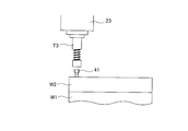
- FIG. 7 is a diagram for explaining the main shaft to which the bolt tool is attached
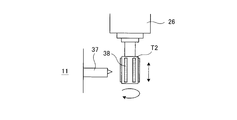
- FIG. 8 is a diagram for explaining the main shaft to which the honing tool is attached. It is.
- the X-axis column 13 When changing the tool, the X-axis column 13 is moved to the replacement work position of the tool magazine 35. For example, when exchanging the tool of the first main spindle 23 from the cutting tool T1 to the bolt tool T3, the X-axis column 13 is moved to the exchanging position of the tool magazine 35, and the cutting tool T1 that is currently empty is used. The gripping part 36 for gripping is also moved to the replacement work position. Then, the cutting tool T1 is returned to the gripping portion 36 in the empty state and gripped. Thereafter, the gripping portion 36 that grips the bolt tool T ⁇ b> 3 is moved to the replacement work position, and the bolt tool T ⁇ b> 3 is attached to the first main shaft 23, thereby performing the tool replacement.
- the bolt tool T3 is attached to the first main shaft 23, and is used when the bolt 41 of the dummy head W2 placed on the cylinder block W1 is tightened or removed. Is done.
- the tightening torque (assembly force) of the bolt 41 is set to a desired magnitude by monitoring the motor load of the first main shaft 23. Try to control.
- the tool itself at the time of tightening and removing the bolt 41 may be changed. For example, when tightening the bolt 41, a bolt tool with a torque wrench function is used, and the torque at the time of tightening the bolt 41 is always constant. It may be made to become. Further, instead of the motor load, a method of monitoring the torque with high accuracy using a force sensor built in the main shaft or a force sensor built in the bolt tool may be used.
- the honing tool T2 is attached to the second spindle 26, but in order to maintain the accuracy of the honing process, it is desirable to adjust the state of the grindstone 38 of the honing tool T2. Therefore, the machine tool 10 of the present embodiment is provided with a dresser 37 on the inner wall portion of the bed 11, and the grinding wheel 38 for grinding (dressing) can be formed using this dresser 37.
- the machine tool 10 of the present embodiment cutting and honing are performed in one apparatus, so that the positional accuracy during the cutting and honing is high, and the honing tool T2 needs to be in a floating state. Therefore, dressing using the dresser 37 is possible, and the state of the grindstone 38 can be adjusted.
- the honing tool T2 is attached to the second main shaft 27, the honing tool T2 is rotated by a predetermined angle by the second main shaft 27, the desired grindstone 38 is selected, and the second Z-axis motor 25 is selected.
- the honing tool T2 can be reciprocated in the Z-axis direction to dress the grindstone 38, and the state can be adjusted.
- the bolt tool T3 is selected from the tool magazine 35 and attached to the first spindle 23 in advance. Further, the honing tool T2 is selected from the tool magazine 35 and attached to the second spindle 26. At that time, as shown in FIG. 6, the first main shaft 23 and the second main shaft 26 are moved to the tool change position together with the X-axis column 13, and a desired tool is attached at each tool change position.
- the cylinder block W1 is transported from another line to the front of the machine tool 10, and the cylinder block W1 is placed and held on the table 32 of the machine tool 10 (see FIG. 3 and the like). Thereafter, the dummy head W2 placed on the placing table 55 is temporarily placed at a predetermined position of the cylinder block W1.
- the dummy head W2 is attached to the cylinder block W1 by tightening a plurality of bolts 41 of the dummy head W2 with a predetermined tightening torque using the bolt tool T3 attached to the first main shaft 23 (the dummy head shown in FIG. 1). Head assembly function B1).
- one dummy head having four openings is attached to the upper surface of the cylinder block.
- the engine is a V-type 6-cylinder engine, as shown in FIG. 9, two dummy heads W2 having three openings 40 are attached to the upper surface of the cylinder block W1.
- the table 32 is also used. Specifically, the cylinder block W1 is rotated together with the table 32 using the table driving device 31 so that the position where the first dummy head W2 is temporarily placed becomes horizontal. Thereafter, the first dummy head W2 is temporarily placed at the position, and the plurality of bolts 41 are tightened with the bolt tool T3 of the first main shaft 23 to attach the dummy head W2 to the cylinder block W1.
- the cylinder block W1 is rotated together with the table 32 using the table driving device 31 so that the position where the second dummy head W2 is temporarily placed is horizontal, and the second dummy head W2 is moved to the position. Is temporarily placed, and a plurality of bolts 41 are tightened with a bolt tool T3 of the first main shaft 23 so that the dummy head W2 is attached to the cylinder block W1.
- the dummy head W2 has openings larger than the machining diameter of the cylinder bore corresponding to each cylinder bore.
- each dummy head W2 is formed with three openings 40 larger than the machining diameter of the cylinder bore corresponding to each cylinder bore. Yes.
- the cutting tool T1 and the honing tool T2 pass through the opening 40 to process the cylinder block W1.
- the tool attached to the first spindle 23 is changed from the bolt tool T3 to the cutting tool T1.
- the bolt tool T ⁇ b> 3 is returned to the tool magazine 35, and the cutting tool T ⁇ b> 1 is selected from the tool magazine 35 and attached to the first spindle 23.
- the cylinder bore is cut into the cylinder block W1 to which the dummy head W2 is assembled, through the opening 40 of the dummy head W2.
- the honing of the cylinder bore is performed on the cylinder block W1 through the opening 40 of the dummy head W2 by using the honing tool T2 attached to the second main shaft 26 (cylinder bore cutting shown in FIG. 1). Processing function B2, cylinder bore honing processing function B3).
- the tool attached to the first spindle 23 is changed from the cutting tool T1 to the bolt tool T3.
- the cutting tool T1 is returned to the tool magazine 35, and the bolt tool T3 is selected from the tool magazine 35 and attached to the first spindle 23.
- the dummy head W2 is removed from the cylinder block W1 by removing the plurality of bolts 41 of the dummy head W2 fastened to the cylinder block W1 using the bolt tool T3 attached to the first main shaft 23 (FIG. 1). Dummy head disassembly function B4) shown.
- the transfer robot 50 Thereafter, using the transfer robot 50, the dummy head W2 on the upper surface of the cylinder block W1 is returned to the placing table 55, and the processed cylinder block W1 is transferred from the machine tool 10 to the next line (see FIG. 3 and the like).
- the machine tool 10 is configured to have two spindles, and a plurality of functions are performed in one machine tool by alternately operating the tools attached to the tips of the two spindles.
- the desired steps can be performed sequentially.
- assembly, cutting and polishing may be performed with only one main spindle. Similarly, it may be further increased depending on the object to be processed.
- the cylinder bore processing on the cylinder block has been described as an example, but the present invention is not limited to this.
- a support member W4 another member
- a crank hole 43 for a crankshaft is machined in the cylinder block W3 together with the support member W4.
- a support member W6 another member
- the connecting rod W5 work
- a bolt 44 a bolt 44
- the crank hole 45 for the crankshaft is machined in the cylinder block W5 together with the support member W6. It is also applicable to.
- the machine tool according to the present invention is particularly suitable for processing a workpiece in a state where parts are assembled. Further, the present invention is not limited to a vertical machine tool, and can be applied to a horizontal machine tool or the like.
Landscapes
- Engineering & Computer Science (AREA)
- Mechanical Engineering (AREA)
- Physics & Mathematics (AREA)
- Geometry (AREA)
- Finish Polishing, Edge Sharpening, And Grinding By Specific Grinding Devices (AREA)
- Automatic Tool Replacement In Machine Tools (AREA)
- Machine Tool Sensing Apparatuses (AREA)
- Grinding-Machine Dressing And Accessory Apparatuses (AREA)
Abstract
部品の組み付け/分解の機能を有すると共に、部品を組み付けた状態で加工できる工作機械を提供する。そのため、第1主軸23及び第2主軸26を有する工作機械10において、シリンダーブロックW1に開口部を有するダミーヘッドW2をボルトにより組み付けると共にボルトを取り外すボルト用工具を、第1主軸23に取り付け、シリンダーブロックW1を研磨するホーニング用工具T2を、第2主軸27に取り付け、ボルト用工具を用いて、シリンダーブロックW1にダミーヘッドW2を組み付け、その後、第1主軸23に取り付ける工具を、シリンダーブロックW1を切削する切削用工具T1に交換し、切削用工具T1、ホーニング用工具T2を用いて、ダミーヘッドW2の開口部を通して、シリンダーブロックW1を加工する。
Description
本発明は、ワークの加工を行う工作機械に関する。
工作機械は、部品(ワーク)1つ1つに対して加工を行うのが一般的であり、その後、加工後の複数の部品を組み付けて、製品を完成するようにしている。
特開2007-237375号公報
特公昭60-052883号公報
特許第3270683号公報
特開昭61-095845号公報
特開昭63-300828号公報
実開平1-106138号公報
製品によっては、複数の部品を組み付けた状態で、工作機械での加工を行わなければならない場合や行ったほうが製品の性能が向上する場合もある。例えば、自動車エンジンを例に取ると、通常、シリンダーブロック単体に工作機械でシリンダーボアの加工、仕上げを行った後、シリンダーブロックにシリンダーヘッドを組み付けて、エンジンを完成している。その場合、シリンダーヘッドの組み付けの際に、組み付け時の力により、ボア内面の形状に変形が発生するおそれがある。そのため、現状では、ピストンのクリアランスを大きく取り、そして、そのクリアランスを埋めるため、ピストンリングの張力も十分大きく取っていた。その結果、ボア内面とピストンリングとの摩擦が増えてしまい、エンジンの燃費悪化の原因となっていた。
従って、燃費向上のためにボア内面の変形を防止するためには、実際のシリンダーヘッドを組み付けた状態で、ボアの加工ができればよいが、それは物理的に不可能であるため、シリンダーヘッドと同等の変形が発生するダミーヘッドを組み付けた状態で、ボアを加工する方法が提案されている。
図12は、ダミーヘッドを用いたシリンダーブロックの工作機械のラインを示すブロック図である。このラインでは、まず、ダミーヘッド組み付け機61を用いて、シリンダーブロックにダミーヘッドを組み付ける。その後、シリンダーボア切削加工機62を用いて、ダミーヘッドが組み付けられたシリンダーブロックにシリンダーボアを切削加工し、次に、シリンダーボアホーニング加工機63を用いて、切削されたシリンダーボアをホーニング加工する。一連の加工終了後、ダミーヘッド分解機64を用いて、シリンダーブロックからダミーヘッドを取り外し、ダミーヘッド搬送装置65を用いて、取り外されたダミーヘッドをダミーヘッド組み付け器61へ搬送している。上記手順を繰り返すことで、ダミーヘッドを取り付けた状態で、シリンダーブロックにシリンダーボアを加工している。
このように、現状では、ダミーヘッド組み付け機61、シリンダーボア切削加工機62、シリンダーボアホーニング加工機63、ダミーヘッド分解機64を別々に設け、ダミーヘッド組み付け機61とダミーヘッド分解機64との間に、シリンダーボア切削加工機62及びシリンダーボアホーニング加工機63を配置し、ダミーヘッド搬送装置65で接続することで、ライン化を図っている。この方法では、ライン全体にかかる設備投資等のコストが高くなり、又、フレキシブルな生産が難しいという問題があった。
更に、作業の効率化のために各装置で同時に作業を行うとなると、装置毎にダミーヘッド及び取り付け用ボルトが必要となり、その分のコストがかかってしまい、又、ダミーヘッドやボルトは使用する度に摩耗、塑性変形していくため、その管理が必要であり、数がおおくなると、その分の管理負担も増大してしまう。
本発明は上記課題に鑑みなされたもので、部品の組み付け/分解の機能を有すると共に、部品を組み付けた状態で加工できる工作機械を提供することを目的とする。
上記課題を解決する第1の発明に係る工作機械は、
少なくとも1つ以上の主軸を有する工作機械において、
ワークに他の部材をボルトにより組み付けると共に前記ボルトを取り外す組付工具を、前記主軸の1つに取り付け、ワークを加工する加工工具を、前記主軸の1つに取り付け、
前記組付工具を用いて、前記ワークに他の部材を組み付け、前記加工工具を用いて、前記ワークを加工することを特徴とする。
少なくとも1つ以上の主軸を有する工作機械において、
ワークに他の部材をボルトにより組み付けると共に前記ボルトを取り外す組付工具を、前記主軸の1つに取り付け、ワークを加工する加工工具を、前記主軸の1つに取り付け、
前記組付工具を用いて、前記ワークに他の部材を組み付け、前記加工工具を用いて、前記ワークを加工することを特徴とする。
上記課題を解決する第2の発明に係る工作機械は、
少なくとも1つ以上の主軸を有する工作機械において、
ワークに他の部材をボルトにより組み付けると共に前記ボルトを取り外す組付工具を、前記主軸の1つに取り付け、他の部材を取り付けた状態でワークを加工する加工工具を、前記主軸の1つに取り付け、
前記組付工具を用いて、前記ワークに他の部材を組み付け、前記加工工具を用いて、前記他の部材と共に前記ワークを加工することを特徴とする。
少なくとも1つ以上の主軸を有する工作機械において、
ワークに他の部材をボルトにより組み付けると共に前記ボルトを取り外す組付工具を、前記主軸の1つに取り付け、他の部材を取り付けた状態でワークを加工する加工工具を、前記主軸の1つに取り付け、
前記組付工具を用いて、前記ワークに他の部材を組み付け、前記加工工具を用いて、前記他の部材と共に前記ワークを加工することを特徴とする。
上記課題を解決する第3の発明に係る工作機械は、
上記第1又は第2の発明に記載の工作機械において、
前記主軸に取り付ける工具を多数収容すると共に、前記主軸へ取り付ける工具を交換する工具交換装置を設け、
当該工具交換装置に収容する工具を、少なくとも前記組付工具及び前記加工工具としたことを特徴とする。
上記第1又は第2の発明に記載の工作機械において、
前記主軸に取り付ける工具を多数収容すると共に、前記主軸へ取り付ける工具を交換する工具交換装置を設け、
当該工具交換装置に収容する工具を、少なくとも前記組付工具及び前記加工工具としたことを特徴とする。
上記課題を解決する第4の発明に係る工作機械は、
上記第1~第3の発明のいずれかに記載の工作機械において、
前記加工工具は、前記ワークを切削する切削工具及び前記ワークを研磨する研磨工具、又は、前記切削工具若しくは前記研磨工具であることを特徴とする。
上記第1~第3の発明のいずれかに記載の工作機械において、
前記加工工具は、前記ワークを切削する切削工具及び前記ワークを研磨する研磨工具、又は、前記切削工具若しくは前記研磨工具であることを特徴とする。
上記課題を解決する第5の発明に係る工作機械は、
上記第4の発明に記載の工作機械において、
前記主軸を2つとすると共に、
一方の主軸を、高出力、高剛性の高能率加工用のものとして、前記組付工具及び前記切削工具を交互に取り付け、
他方の主軸を、軽量で高速、高精度な精密加工用のものとして、前記研磨工具を取り付けることを特徴とする。
上記第4の発明に記載の工作機械において、
前記主軸を2つとすると共に、
一方の主軸を、高出力、高剛性の高能率加工用のものとして、前記組付工具及び前記切削工具を交互に取り付け、
他方の主軸を、軽量で高速、高精度な精密加工用のものとして、前記研磨工具を取り付けることを特徴とする。
上記課題を解決する第6の発明に係る工作機械は、
上記第4又は第5の発明に記載の工作機械において、
前記研磨工具を成型するためのドレッサーを設け、
前記主軸に前記研磨工具を取り付けて、前記研磨工具を成型することを特徴とする。
上記第4又は第5の発明に記載の工作機械において、
前記研磨工具を成型するためのドレッサーを設け、
前記主軸に前記研磨工具を取り付けて、前記研磨工具を成型することを特徴とする。
上記課題を解決する第7の発明に係る工作機械は、
上記第1~第6の発明のいずれかに記載の工作機械において、
当該工作機械の機内又は機外に、前記ワークに前記他の部材を仮置きすると共に、前記ボルトを取り外した後の前記他の部材を前記ワークから搬出する搬送装置を設けたことを特徴とする。
上記第1~第6の発明のいずれかに記載の工作機械において、
当該工作機械の機内又は機外に、前記ワークに前記他の部材を仮置きすると共に、前記ボルトを取り外した後の前記他の部材を前記ワークから搬出する搬送装置を設けたことを特徴とする。
上記課題を解決する第8の発明に係る工作機械は、
上記第1~第7の発明のいずれかに記載の工作機械において、
前記主軸に取り付けた前記組付工具を用いて、前記ワークに前記他の部材を組み付ける場合、当該主軸の負荷を監視することにより、組み付け時の組み付け力を制御することを特徴とする。
上記第1~第7の発明のいずれかに記載の工作機械において、
前記主軸に取り付けた前記組付工具を用いて、前記ワークに前記他の部材を組み付ける場合、当該主軸の負荷を監視することにより、組み付け時の組み付け力を制御することを特徴とする。
本発明によれば、工作機械内で部品の組み付け/分解を行うことで、工程を1つの工作機械に集約し、組み付けにかかる設備のコストを大幅に低減し、更に、フレキシブルな生産を実現することができる。
10 工作機械
11 ベッド
13 X軸コラム
16 Z軸コラム
23 第1主軸
26 第2主軸
32 テーブル
35 工具マガジン
37 ドレッサー
50 搬送ロボット
T1 切削用工具
T2 ホーニング用工具
T3 ボルト用工具
W1 シリンダーブロック
W2 ダミーヘッド
11 ベッド
13 X軸コラム
16 Z軸コラム
23 第1主軸
26 第2主軸
32 テーブル
35 工具マガジン
37 ドレッサー
50 搬送ロボット
T1 切削用工具
T2 ホーニング用工具
T3 ボルト用工具
W1 シリンダーブロック
W2 ダミーヘッド
以下、本発明に係る工作機械の実施形態例を、図1~図11を用いて説明する。
(実施例1)
図1は、本実施例の工作機械を説明するブロック図である。又、図2は、本実施例の工作機械と搬送装置とを図示した斜視図であり、図3は、本実施例の工作機械と搬送装置とを図示した上面図、図4は、本実施例の工作機械と搬送装置とを図示した側面図である。又、図5は、本実施例の工作機械を示す正面図である。なお、ここでは、ワークが配置される部分を正面又は前面としている。又、本実施例では、エンジンのシリンダーボア加工を例にとって説明をするが、後述するように、組付け後の加工を行っている他の製品の加工にも適用可能である。
図1は、本実施例の工作機械を説明するブロック図である。又、図2は、本実施例の工作機械と搬送装置とを図示した斜視図であり、図3は、本実施例の工作機械と搬送装置とを図示した上面図、図4は、本実施例の工作機械と搬送装置とを図示した側面図である。又、図5は、本実施例の工作機械を示す正面図である。なお、ここでは、ワークが配置される部分を正面又は前面としている。又、本実施例では、エンジンのシリンダーボア加工を例にとって説明をするが、後述するように、組付け後の加工を行っている他の製品の加工にも適用可能である。
本実施例の工作機械10は、1つの工作機械内において、少なくとも、部品の組み付け/分解の機能と、部品を組み付けた状態で加工できる機能とを有し、これらの機能による工程を1つの工作機械に集約したものである。例えば、エンジンのシリンダーボア加工の場合には、図1に示すように、ダミーヘッド組み付け機能B1、シリンダーボア切削加工機能B2、シリンダーボアホーニング加工機能B3、ダミーヘッド分解機能B4を有している。従来と比較すると(図12参照)、ダミーヘッド搬送用の装置が不要となり、装置コストの削減が可能である。
本実施例の工作機械10における一連の工程の概略を説明すると、順に、ダミーヘッド組み付け機能B1において、ダミーヘッドをシリンダーブロックに組み付け、シリンダーボア切削加工機能B2において、ダミーヘッドを組み付けたシリンダーブロックにシリンダーボアの切削加工を行い、シリンダーボアホーニング加工機能B3において、ダミーヘッドを組み付けて切削加工したシリンダーブロックにシリンダーボアのホーニング加工を行い、ダミーヘッド分解機能B4において、加工後のシリンダーブロックからダミーヘッドを分解することになる。
次に、上記機能を有する本実施例の工作機械10の構成を、図2~図5を用いて、具体的に説明をする。
本実施例の工作機械10には、その下部に1対のベッド11が設けられている。1対のベッド11の上面には、Y軸方向に平行に1対のガイドレール12が設けられており、1対のガイドレール12を介して、ベッド11上にX軸コラム13が設けられている。このX軸コラム13は、ベッド11の後側に設けられたY軸モータ14により、ガイドレール12上をY軸方向に往復移動可能となっている。
又、X軸コラム13にも、X軸方向に平行に1対のガイドレール15が設けられており、1対のガイドレール15を介して、X軸コラム13の前面にZ軸コラム16が設けられている。このZ軸コラム16は、X軸コラム13に設けられたX軸モータ17により、ガイドレール15上をX軸方向に往復移動可能となっている。
Z軸コラム16の前面側には、Z軸方向に平行に2対のガイドレール21、24が設けられおり、ガイドレール21を介して第1主軸23が、ガイドレール24を介して第2主軸26が、Z軸コラム16に設けられている。第1主軸23には、その上部に第1Z軸モータ22が設けられ、その先端に切削用工具T1が取り付けられている。又、第2主軸26には、その上部に第2Z軸モータ25が設けられ、その先端にホーニング用工具T2が取り付けられている。そして、第1主軸23は、第1Z軸モータ22により、ガイドレール21上をZ軸(鉛直)方向に往復移動可能となっており、又、第2主軸26は、第2Z軸モータ25により、ガイドレール24上をZ軸方向に往復移動可能となっている。
このように、本実施例の工作機械10は、第1主軸23と第2主軸26からなる2つの主軸を有し、それらを鉛直(Z軸)方向に立設させた構成である。そして、第1主軸23、第2主軸26は、共に鉛直方向の旋回軸を有し、又、各々独立してZ軸方向に移動可能であり、ワーク(シリンダーブロックW1、ダミーヘッドW2)に対して鉛直方向に各々異なる加工を行うことが可能である。
1対のベッド11の間の前側の空間には、ワークを保持するためのテーブル32が設けられている。このテーブル32は、ベッド11に設けられたテーブル駆動装置31により、X軸と平行な軸を回転軸として、回転可能になっている。従って、テーブル32にワークを保持させた後、テーブル駆動装置31でテーブル32を所望の角度に回転させることにより、切削用工具T1、ホーニング用T2による加工を所望の方向に行うことが可能である。
又、1対のベッド11間の中央部から後方にかけて、工具を多数収容する長円形状の工具マガジン35(工具交換装置)が配置されている。工具マガジン35には、工具を把持するように構成された把持部36を、ループ状に複数配置している。この把持部36は、図示しない駆動モータにより、ベッド11の上面と平行な平面上を順次周回移動可能となっている。工具交換の際には、所望の工具を把持する把持部36を工具交換位置まで移動し(後述の図6参照)、その工具交換位置へ第1主軸23、第2主軸26を移動させることで、第1主軸23、第2主軸26へ取り付ける工具を、所望の工具へ交換可能となっている。
このように、第1主軸23、第2主軸26において、工具は着脱可能である。従って、本実施例の工作機械10において、工具マガジン35は、少なくとも、ワークを切削する切削用工具T1(加工工具/切削工具)と、ワークを研磨するホーニング用工具T2(加工工具/研磨工具)と、ボルトによる部品の組み付け/取り外しを行うボルト用工具T3(組付工具)とを有する。切削用工具T1、ボルト用工具T3は、第1主軸23側へ交互に取り付け、ホーニング用工具T2は、第2主軸26側へ取り付けている。なお、第1主軸23は、主軸ヘッドが高出力、高剛性の高能率加工用のものがよく、第2主軸26は、軽量で高精度な精密加工用のものがよい。このように、第1主軸23と第2主軸26とは、各々用途が異なり、異なる加工をワークに対して実施可能である。又、高能率にホーニング加工を行う場合、ホーニング加工用工具T2を高出力の第1主軸23に取り付けて加工してもよい。
又、本実施例の工作機械10は、ホーニング用工具T2を成型するためのドレッサー37を有しており、このドレッサー37をベッド11に設けている。
本実施例の工作機械10の機外には、ワーク搬送用の搬送ロボット50(搬送装置)が設けられている。搬送ロボット50は、工作機械10の前方に配置されたものであり、X軸方向に平行な1対の搬送レール51と、1対の搬送レール51上に設けられた搬送台52と、搬送台52に上に設けられ、搬送台52をX軸方向に往復移動可能とする搬送用モータ54と、搬送台52に設けられ、ワークであるシリンダーブロックW1、ダミーヘッドW2を各々保持して搬送するロボットアーム54とを有している。又、組み付け前のダミーヘッドW2を置くための置き台55が搬送台52に設けられている。
この搬送ロボット50は、他のラインからのシリンダーブロックW1をロボットアーム54に保持して、工作機械10の正面まで搬送し、その後、シリンダーブロックW1を工作機械10のテーブル32に乗せている。そして、シリンダーブロックW1をテーブル32に保持させた後、置き台55上のダミーヘッドW2を、ロボットアーム54を用いて、シリンダーブロックW1上に仮置きしている。このダミーヘッドW2は、加工前に、工作機械10のボルト用工具T3を用いて、シリンダーブロックW1に取り付けられ、一連の加工の終了後には、ボルト用工具T3を用いて、シリンダーブロックW1から取り外される。その後、搬送ロボット50は、ロボットアーム54を用いて、シリンダーブロックW1から取り外したダミーヘッドW2を置き台55上に乗せた後、シリンダーブロックW1を保持して、他のラインへ搬送することになる。なお、ダミーヘッドW2の搬送機能については、工作機械10の機内に別途設けるようにしてもよい。
次に、図6~図8を用いて、本実施例の工作機械10での工具交換及び本実施例の工作機械10で使用する工具について説明する。なお、図6は、工具交換時における本実施例の工作機械を示す斜視図であり、図7は、ボルト用工具を取り付けた主軸、図8は、ホーニング用工具を取り付けた主軸を説明する図である。
工具交換の際には、X軸コラム13を工具マガジン35の交換作業位置まで移動して行う。例えば、第1主軸23の工具を切削用工具T1からボルト用工具T3に交換する場合には、X軸コラム13を工具マガジン35の交換作業位置まで移動し、現在空状態である切削用工具T1把持用の把持部36も交換作業位置まで移動させる。そして、空状態の把持部36に切削用工具T1を戻して把持させる。その後、ボルト用工具T3を把持している把持部36を交換作業位置へ移動させて、第1主軸23にボルト用工具T3を取り付けることで、工具交換が実施される。
このボルト用工具T3は、図7に示すように、第1主軸23に取り付けられており、シリンダーブロックW1上に乗せられたダミーヘッドW2のボルト41を締め付けたり、又は、取り外したりするときに使用される。第1主軸23に取り付けられたボルト用工具T3を用いて、ボルト41を締め付けるときには、第1主軸23のモータ負荷を監視することにより、ボルト41の締め付けトルク(組み付け力)を所望の大きさに制御するようにする。又、ボルト41の締め付けるときと、取り外すときの工具自体を変更しても良く、例えば、ボルト41の締め付けるときには、トルクレンチ機能付きのボルト用工具を用い、ボルト41の締め付け時のトルクが常に一定になるようにしてもよい。又、モータ負荷ではなく、主軸内部に内臓された力センサやボルト用工具内部に内蔵された力センサを用いて、高精度にトルクを監視する方法をとってもよい。
又、第2主軸26には、ホーニング用工具T2が取り付けられるが、ホーニング加工の精度を保つためには、ホーニング用工具T2の砥石38の状態を整えることが望ましい。そのため、本実施例の工作機械10には、ベッド11の内壁部分にドレッサー37が設けてあり、このドレッサー37を用いて、研削用の砥石38の成型(ドレッシング)が可能である。
従来、シリンダーボアの切削加工とホーニング加工とは、別々の装置で行われていたため、後の工程となるホーニング加工では、切削加工の位置に追従できるようにホーニング加工を行う必要があり、そのため、ホーニング用工具はフローティング状態で保持されていた。ところが、ホーニング用工具がフローティング状態である場合、ドレッシングを行いたくても、ホーニング用工具が動いてしまい、ドレッシングを実施することは難しかった。従って、一旦ホーニング用工具を取り外し、円筒研削盤を用いて成型を行うため、稼動を大きく阻害していた。
これに対して、本実施例の工作機械10では、1つの装置内で切削加工、ホーニング加工を行うため、切削加工、ホーニング加工時の位置精度が高く、ホーニング用工具T2をフローティング状態とする必要がなくなるため、ドレッサー37を用いたドレッシングが可能となり、砥石38の状態を整えることができる。ドレッシングを行う際には、第2主軸27にホーニング用工具T2を取り付けて、第2主軸27によりホーニング用工具T2を所定角度回転させて、所望の砥石38を選択すると共に、第2Z軸モータ25によりホーニング用工具T2をZ軸方向に往復移動させて、砥石38をドレッシングして、その状態を整えることができる。
次に、シリンダーブロックへのシリンダーボア加工を例にとり、前述の図1~図9も参照して、一連の工程の動作を説明する。
予め、工作機械10において、第1主軸23に対して、工具マガジン35からボルト用工具T3を選択して、取り付けておく。又、第2主軸26に対しては、工具マガジン35からホーニング用工具T2を選択して、取り付けておく。その際には、図6に示すように、X軸コラム13と共に第1主軸23、第2主軸26を工具交換位置へ移動し、各々、工具交換位置において、所望の工具を取り付けている。
次に、搬送ロボット50を用いて、シリンダーブロックW1を他のラインから工作機械10の正面まで搬送し、工作機械10のテーブル32にシリンダーブロックW1を置いて保持させる(図3等参照)。その後、置き台55に置いてあるダミーヘッドW2をシリンダーブロックW1の所定位置に仮置きする。
そして、第1主軸23に取り付けたボルト用工具T3を用い、ダミーヘッドW2の複数のボルト41を所定の締め付けトルクで締め付けることにより、ダミーヘッドW2をシリンダーブロックW1へ取り付ける(図1で示したダミーヘッド組み付け機能B1)。
例えば、エンジンが直列4気筒エンジンである場合、シリンダーブロックの上面に、4つの開口部を有するダミーヘッドを1つ取り付けることになる。又、エンジンがV型6気筒エンジンである場合、図9に示すように、シリンダーブロックW1の上面に、3つの開口部40を有するダミーヘッドW2を2つ取り付けることになる。
又、V型6気筒エンジンである場合には、ダミーヘッドW2を2つ取り付ける必要があるが、その場合には、テーブル32も使用している。具体的には、1つ目のダミーヘッドW2を仮置きする位置が水平となるように、テーブル駆動装置31を用いて、テーブル32と共にシリンダーブロックW1を回転している。その後、当該位置に1つ目のダミーヘッドW2を仮置きし、第1主軸23のボルト用工具T3で複数のボルト41を締め付けて、ダミーヘッドW2をシリンダーブロックW1へ取り付けている。同様に、2つ目のダミーヘッドW2を仮置きする位置が水平となるように、テーブル駆動装置31を用いて、テーブル32と共にシリンダーブロックW1を回転し、当該位置に2つ目のダミーヘッドW2を仮置きし、第1主軸23のボルト用工具T3で複数のボルト41を締め付けて、ダミーヘッドW2をシリンダーブロックW1へ取り付けるようにしている。
なお、ダミーヘッドW2には、各シリンダーボアに対応して、シリンダーボアの加工径より大きい開口部が形成されている。例えば、シリンダーブロックW1がV型6気筒エンジン用である場合には、各ダミーヘッドW2には、シリンダーボアの加工径より大きい3つの開口部40が、各々のシリンダーボアに対応して形成されている。切削用工具T1、ホーニング用工具T2は、この開口部40を通って、シリンダーブロックW1への加工を行うことになる。
ダミーヘッドW2をシリンダーブロックW1へ取り付けた後、第1主軸23に取り付ける工具を、ボルト用工具T3から切削用工具T1へ変更する。この場合、工具マガジン35へボルト用工具T3を戻すと共に、工具マガジン35から切削用工具T1を選択して、第1主軸23に取り付ける。
そして、第1主軸23に取り付けた切削用工具T1を用い、ダミーヘッドW2の開口部40を通して、ダミーヘッドW2を組み付けたシリンダーブロックW1にシリンダーボアの切削加工を行う。切削加工後、今度は、第2主軸26に取り付けたホーニング用工具T2を用い、ダミーヘッドW2の開口部40を通して、シリンダーブロックW1にシリンダーボアのホーニング加工を行う(図1で示したシリンダーボア切削加工機能B2、シリンダーボアホーニング加工機能B3)。
この一連の加工工程において、シリンダーブロックW1を保持するテーブル32側は動かす必要はなく、Z軸コラム16をX軸モータ17によりX軸方向に動かせば、所望の加工位置において、第1主軸23から第2主軸26へ変更することになる。そのため、加工時の位置精度を確保した状態で、切削加工に続き、ホーニング加工を実施することになり、従来のように、ホーニング工具T2をフローティングさせて保持する必要はない。又、シリンダーブロックW1へのシリンダーボアの切削加工、ホーニング加工は、ダミーヘッドW2を組み付けた状態で行っているので、実際のシリンダーヘッドを組み付けたときのシリンダーボア内面の変形を抑制することができる。
一連の加工工程後、第1主軸23に取り付ける工具を、切削用工具T1からボルト用工具T3へ変更する。この場合、工具マガジン35へ切削用工具T1を戻すと共に、工具マガジン35からボルト用工具T3を選択して、第1主軸23に取り付ける。
そして、第1主軸23に取り付けたボルト用工具T3を用い、シリンダーブロックW1へ締め付けたダミーヘッドW2の複数のボルト41を取り外すことにより、ダミーヘッドW2をシリンダーブロックW1から取り外している(図1で示したダミーヘッド分解機能B4)。
その後、搬送ロボット50を用いて、シリンダーブロックW1上面のダミーヘッドW2を置き台55へ戻すと共に、加工後のシリンダーブロックW1を工作機械10から次のラインへ搬送する(図3等参照)。
このように、本実施例の工作機械10は、2つの主軸を有する構成であり、2つの主軸の先端に取り付けた工具を交互に動作させることにより、1つの工作機械内で複数の機能を実施することができ、所望の工程を順次実施可能にしている。その結果、複数の工程を1つの工作機械に集約し、組み付けにかかる設備のコストを大幅に低減可能とし、更に、フレキシブルな生産を実現することもできる。なお、高精度、若しくは、高速加工が要求されない場合は、1つの主軸だけで組み付け、切削及び研磨加工を行ってもよい。同様に、加工対象によっては更に増やすようにしてもよい。
上述したように、本実施例では、シリンダーブロックへのシリンダーボア加工を例にとって説明してきたが、本発明は、それだけに限るものではない。例えば、図10に示すように、シリンダーブロックW3(ワーク)に支持部材W4(他の部材)をボルト42で取り付け、支持部材W4と共にシリンダーブロックW3に、クランクシャフト用のクランク穴43を加工する場合や、図11に示すように、コンロッドW5(ワーク)に支持部材W6(他の部材)をボルト44で取り付け、支持部材W6と共にシリンダーブロックW5に、クランクシャフト用のクランク穴45を加工する場合等にも適用可能である。
本発明に係る工作機械は、特に、部品同士を組み付けた状態でワークの加工を行う場合に好適なものである。又、立形工作機械に限定することはなく、横形工作機械等にも適用可能である。
Claims (8)
- 少なくとも1つ以上の主軸を有する工作機械において、
ワークに他の部材をボルトにより組み付けると共に前記ボルトを取り外す組付工具を、前記主軸の1つに取り付け、ワークを加工する加工工具を、前記主軸の1つに取り付け、
前記組付工具を用いて、前記ワークに他の部材を組み付け、前記加工工具を用いて、前記ワークを加工することを特徴とする工作機械。 - 少なくとも1つ以上の主軸を有する工作機械において、
ワークに他の部材をボルトにより組み付けると共に前記ボルトを取り外す組付工具を、前記主軸の1つに取り付け、他の部材を取り付けた状態でワークを加工する加工工具を、前記主軸の1つに取り付け、
前記組付工具を用いて、前記ワークに他の部材を組み付け、前記加工工具を用いて、前記他の部材と共に前記ワークを加工することを特徴とする工作機械。 - 請求項1又は請求項2に記載の工作機械において、
前記主軸に取り付ける工具を多数収容すると共に、前記主軸へ取り付ける工具を交換する工具交換装置を設け、
当該工具交換装置に収容する工具を、少なくとも前記組付工具及び前記加工工具としたことを特徴とする工作機械。 - 請求項1から請求項3のいずれかに記載の工作機械において、
前記加工工具は、前記ワークを切削する切削工具及び前記ワークを研磨する研磨工具、又は、前記切削工具若しくは前記研磨工具であることを特徴とする工作機械。 - 請求項4に記載の工作機械において、
前記主軸を2つとすると共に、
一方の主軸を、高出力、高剛性の高能率加工用のものとして、前記組付工具及び前記切削工具を交互に取り付け、
他方の主軸を、軽量で高速、高精度な精密加工用のものとして、前記研磨工具を取り付けることを特徴とする工作機械。 - 請求項4又は請求項5に記載の工作機械において、
前記研磨工具を成型するためのドレッサーを設け、
前記主軸に前記研磨工具を取り付けて、前記研磨工具を成型することを特徴とする工作機械。 - 請求項1乃至請求項6のいずれかに記載の工作機械において、
当該工作機械の機内又は機外に、前記ワークに前記他の部材を仮置きすると共に、前記ボルトを取り外した後の前記他の部材を前記ワークから搬出する搬送装置を設けたことを特徴とする工作機械。 - 請求項1乃至請求項7のいずれかに記載の工作機械において、
前記主軸に取り付けた前記組付工具を用いて、前記ワークに前記他の部材を組み付ける場合、当該主軸の負荷を監視することにより、組み付け時の組み付け力を制御することを特徴とする工作機械。
Applications Claiming Priority (2)
| Application Number | Priority Date | Filing Date | Title |
|---|---|---|---|
| JP2008334155A JP2010155300A (ja) | 2008-12-26 | 2008-12-26 | 工作機械 |
| JP2008-334155 | 2008-12-26 |
Publications (1)
| Publication Number | Publication Date |
|---|---|
| WO2010073823A1 true WO2010073823A1 (ja) | 2010-07-01 |
Family
ID=42287448
Family Applications (1)
| Application Number | Title | Priority Date | Filing Date |
|---|---|---|---|
| PCT/JP2009/068924 Ceased WO2010073823A1 (ja) | 2008-12-26 | 2009-11-05 | 工作機械 |
Country Status (2)
| Country | Link |
|---|---|
| JP (1) | JP2010155300A (ja) |
| WO (1) | WO2010073823A1 (ja) |
Cited By (5)
| Publication number | Priority date | Publication date | Assignee | Title |
|---|---|---|---|---|
| EP2656965B1 (de) * | 2012-04-27 | 2017-11-29 | HOMAG GmbH | Bearbeitungsvorrichtung mit Werkzeugwechselanordnung, insbesondere Kettenwechsler |
| JP2018075667A (ja) * | 2016-11-10 | 2018-05-17 | 株式会社スギノマシン | 工作機械 |
| CN111215903A (zh) * | 2019-11-27 | 2020-06-02 | 安徽枫雅轩科技信息服务有限公司 | 一种曲轴端面加工装置 |
| CN118123506A (zh) * | 2024-03-27 | 2024-06-04 | 黄鹄(浙江)精密机床有限公司 | 一种带有对传动装置降温系统的数控加工机床 |
| EP4729231A1 (de) * | 2024-10-21 | 2026-04-22 | Weinmann Holzbausystemtechnik GmbH | Vorrichtung und verfahren zum prozessieren von werkstücken mit einer stationären lagerstation für aggregate zur prozessautomatisierung |
Families Citing this family (10)
| Publication number | Priority date | Publication date | Assignee | Title |
|---|---|---|---|---|
| JP2013039627A (ja) * | 2011-08-11 | 2013-02-28 | Takemasa:Kk | 超音波加工機の自動工具交換装置 |
| DE202015009036U1 (de) | 2015-05-06 | 2016-07-25 | Gehring Technologies Gmbh | Honmaschine mit einem Maschinengestell und mindestens zwei beidseits des Maschinengestells angeordneten Einheiten |
| WO2018051476A1 (ja) * | 2016-09-16 | 2018-03-22 | 富士機械製造株式会社 | ワーク自動搬送機 |
| JP6661031B2 (ja) | 2016-11-29 | 2020-03-11 | 株式会社Fuji | 多関節ロボットアーム |
| CN107470908B (zh) * | 2017-06-30 | 2019-01-18 | 嘉善梦溪服饰辅料厂(普通合伙) | 一种工件加工的辅助装置 |
| CN107520659B (zh) * | 2017-06-30 | 2019-03-08 | 嘉善梦溪服饰辅料厂(普通合伙) | 一种用于工件加工中的辅助装置 |
| JP6927779B2 (ja) * | 2017-07-18 | 2021-09-01 | トーヨーエイテック株式会社 | 加工装置及びそれを用いた加工方法 |
| JP7104506B2 (ja) * | 2017-10-31 | 2022-07-21 | トーヨーエイテック株式会社 | 内周面加工装置及び内周面加工方法 |
| DE102018213131B4 (de) | 2018-08-06 | 2024-08-14 | Nagel Maschinen- Und Werkzeugfabrik Gmbh | Bearbeitungssystem zur spanenden Bearbeitung von Werkstücken mit Bohrung |
| CN111390564A (zh) * | 2020-04-16 | 2020-07-10 | 耿彪 | 一种用于阀门法兰盘钻孔打磨装置 |
Citations (6)
| Publication number | Priority date | Publication date | Assignee | Title |
|---|---|---|---|---|
| JPS6052883B2 (ja) * | 1980-12-19 | 1985-11-21 | 本田技研工業株式会社 | 中ぐりとホ−ニングの複合加工装置 |
| JPH01106138U (ja) * | 1988-01-11 | 1989-07-17 | ||
| JP3270683B2 (ja) * | 1996-05-22 | 2002-04-02 | 本田技研工業株式会社 | 複合加工装置 |
| JP2007237375A (ja) * | 2006-03-13 | 2007-09-20 | Honda Motor Co Ltd | 複合工作機械 |
| WO2007119334A1 (ja) * | 2006-03-13 | 2007-10-25 | Honda Motor Co., Ltd. | ツールヘッド、工作機械及び該工作機械を用いたシリンダブロックのボアの中ぐり加工方法 |
| JP2008183666A (ja) * | 2007-01-30 | 2008-08-14 | Yamazaki Mazak Corp | マシニングセンタ |
-
2008
- 2008-12-26 JP JP2008334155A patent/JP2010155300A/ja not_active Withdrawn
-
2009
- 2009-11-05 WO PCT/JP2009/068924 patent/WO2010073823A1/ja not_active Ceased
Patent Citations (6)
| Publication number | Priority date | Publication date | Assignee | Title |
|---|---|---|---|---|
| JPS6052883B2 (ja) * | 1980-12-19 | 1985-11-21 | 本田技研工業株式会社 | 中ぐりとホ−ニングの複合加工装置 |
| JPH01106138U (ja) * | 1988-01-11 | 1989-07-17 | ||
| JP3270683B2 (ja) * | 1996-05-22 | 2002-04-02 | 本田技研工業株式会社 | 複合加工装置 |
| JP2007237375A (ja) * | 2006-03-13 | 2007-09-20 | Honda Motor Co Ltd | 複合工作機械 |
| WO2007119334A1 (ja) * | 2006-03-13 | 2007-10-25 | Honda Motor Co., Ltd. | ツールヘッド、工作機械及び該工作機械を用いたシリンダブロックのボアの中ぐり加工方法 |
| JP2008183666A (ja) * | 2007-01-30 | 2008-08-14 | Yamazaki Mazak Corp | マシニングセンタ |
Cited By (5)
| Publication number | Priority date | Publication date | Assignee | Title |
|---|---|---|---|---|
| EP2656965B1 (de) * | 2012-04-27 | 2017-11-29 | HOMAG GmbH | Bearbeitungsvorrichtung mit Werkzeugwechselanordnung, insbesondere Kettenwechsler |
| JP2018075667A (ja) * | 2016-11-10 | 2018-05-17 | 株式会社スギノマシン | 工作機械 |
| CN111215903A (zh) * | 2019-11-27 | 2020-06-02 | 安徽枫雅轩科技信息服务有限公司 | 一种曲轴端面加工装置 |
| CN118123506A (zh) * | 2024-03-27 | 2024-06-04 | 黄鹄(浙江)精密机床有限公司 | 一种带有对传动装置降温系统的数控加工机床 |
| EP4729231A1 (de) * | 2024-10-21 | 2026-04-22 | Weinmann Holzbausystemtechnik GmbH | Vorrichtung und verfahren zum prozessieren von werkstücken mit einer stationären lagerstation für aggregate zur prozessautomatisierung |
Also Published As
| Publication number | Publication date |
|---|---|
| JP2010155300A (ja) | 2010-07-15 |
Similar Documents
| Publication | Publication Date | Title |
|---|---|---|
| WO2010073823A1 (ja) | 工作機械 | |
| CN1157276C (zh) | 对夹固在夹具中的曲轴进行的粗磨和精磨 | |
| EP2246136B1 (en) | Machine and method for machining crankshaft ends | |
| CN1646247A (zh) | 在加工机床或铣床中从各个方向加工毛坯的方法及装置 | |
| CN107322428A (zh) | 基于复合式机器人去毛刺设备 | |
| WO2010088181A2 (en) | Machining center for a wind turbine hub | |
| JP2010030011A (ja) | 研削盤および研削盤のエクステンション・スピンドル交換方法 | |
| JP4741188B2 (ja) | ブランクを全面的に加工するための方法及び装置 | |
| JP4381542B2 (ja) | クランクシャフトの複合加工装置 | |
| JPH10156669A (ja) | 自動工作機械および被加工物の処理方法 | |
| MX2015001753A (es) | Maquina herramienta. | |
| KR101209995B1 (ko) | 크랭크샤프트 디버링용 로봇핸드 | |
| WO2011145698A1 (ja) | 砥石、砥石の製造方法、中ぐり工具、砥粒位置決め治具、及び、逃げ面成形方法 | |
| CN103286327A (zh) | 一种数控凸轮自动车床 | |
| CN207326659U (zh) | 基于复合式机器人去毛刺设备 | |
| CN103770017A (zh) | 一种用于成套齿轮喷丸强化处理的夹具 | |
| CN201889695U (zh) | 凸轮轴磨床的定相位装置 | |
| JP2004090203A (ja) | ルーツロータ加工方法及び加工装置 | |
| CN212020227U (zh) | 一种减震器惯性环的端面加工固定工装 | |
| KR20090057679A (ko) | 커넥팅 로드 디버링 복합 가공 장치 | |
| WO1998012009A1 (en) | Machining apparatus for works having non-circular curves | |
| JP3835578B2 (ja) | ピストンリングの複合加工装置 | |
| CN223848791U (zh) | 一种批头套筒磨削加工装置 | |
| CN202129690U (zh) | 一种具有双工作站的外圆磨床 | |
| JP5769146B2 (ja) | 旋盤 |
Legal Events
| Date | Code | Title | Description |
|---|---|---|---|
| 121 | Ep: the epo has been informed by wipo that ep was designated in this application |
Ref document number: 09834627 Country of ref document: EP Kind code of ref document: A1 |
|
| NENP | Non-entry into the national phase |
Ref country code: DE |
|
| 122 | Ep: pct application non-entry in european phase |
Ref document number: 09834627 Country of ref document: EP Kind code of ref document: A1 |