WO2010073830A1 - 通信システム及び移動局装置 - Google Patents
通信システム及び移動局装置 Download PDFInfo
- Publication number
- WO2010073830A1 WO2010073830A1 PCT/JP2009/069043 JP2009069043W WO2010073830A1 WO 2010073830 A1 WO2010073830 A1 WO 2010073830A1 JP 2009069043 W JP2009069043 W JP 2009069043W WO 2010073830 A1 WO2010073830 A1 WO 2010073830A1
- Authority
- WO
- WIPO (PCT)
- Prior art keywords
- cell
- measurement
- station apparatus
- base station
- frequency
- Prior art date
- Legal status (The legal status is an assumption and is not a legal conclusion. Google has not performed a legal analysis and makes no representation as to the accuracy of the status listed.)
- Ceased
Links
Images


Classifications
-
- H—ELECTRICITY
- H04—ELECTRIC COMMUNICATION TECHNIQUE
- H04W—WIRELESS COMMUNICATION NETWORKS
- H04W24/00—Supervisory, monitoring or testing arrangements
- H04W24/10—Scheduling measurement reports ; Arrangements for measurement reports
-
- H—ELECTRICITY
- H04—ELECTRIC COMMUNICATION TECHNIQUE
- H04W—WIRELESS COMMUNICATION NETWORKS
- H04W36/00—Hand-off or reselection arrangements
- H04W36/0005—Control or signalling for completing the hand-off
- H04W36/0083—Determination of parameters used for hand-off, e.g. generation or modification of neighbour cell lists
- H04W36/0085—Hand-off measurements
- H04W36/0094—Definition of hand-off measurement parameters
-
- H—ELECTRICITY
- H04—ELECTRIC COMMUNICATION TECHNIQUE
- H04B—TRANSMISSION
- H04B17/00—Monitoring; Testing
- H04B17/30—Monitoring; Testing of propagation channels
- H04B17/309—Measuring or estimating channel quality parameters
-
- H—ELECTRICITY
- H04—ELECTRIC COMMUNICATION TECHNIQUE
- H04L—TRANSMISSION OF DIGITAL INFORMATION, e.g. TELEGRAPHIC COMMUNICATION
- H04L1/00—Arrangements for detecting or preventing errors in the information received
- H04L1/12—Arrangements for detecting or preventing errors in the information received by using return channel
- H04L1/16—Arrangements for detecting or preventing errors in the information received by using return channel in which the return channel carries supervisory signals, e.g. repetition request signals
- H04L1/18—Automatic repetition systems, e.g. Van Duuren systems
- H04L1/1812—Hybrid protocols; Hybrid automatic repeat request [HARQ]
-
- H—ELECTRICITY
- H04—ELECTRIC COMMUNICATION TECHNIQUE
- H04L—TRANSMISSION OF DIGITAL INFORMATION, e.g. TELEGRAPHIC COMMUNICATION
- H04L1/00—Arrangements for detecting or preventing errors in the information received
- H04L1/20—Arrangements for detecting or preventing errors in the information received using signal quality detector
-
- H—ELECTRICITY
- H04—ELECTRIC COMMUNICATION TECHNIQUE
- H04W—WIRELESS COMMUNICATION NETWORKS
- H04W24/00—Supervisory, monitoring or testing arrangements
- H04W24/08—Testing, supervising or monitoring using real traffic
-
- H—ELECTRICITY
- H04—ELECTRIC COMMUNICATION TECHNIQUE
- H04L—TRANSMISSION OF DIGITAL INFORMATION, e.g. TELEGRAPHIC COMMUNICATION
- H04L1/00—Arrangements for detecting or preventing errors in the information received
- H04L1/0001—Systems modifying transmission characteristics according to link quality, e.g. power backoff
- H04L1/0002—Systems modifying transmission characteristics according to link quality, e.g. power backoff by adapting the transmission rate
- H04L1/0003—Systems modifying transmission characteristics according to link quality, e.g. power backoff by adapting the transmission rate by switching between different modulation schemes
-
- H—ELECTRICITY
- H04—ELECTRIC COMMUNICATION TECHNIQUE
- H04L—TRANSMISSION OF DIGITAL INFORMATION, e.g. TELEGRAPHIC COMMUNICATION
- H04L1/00—Arrangements for detecting or preventing errors in the information received
- H04L1/0001—Systems modifying transmission characteristics according to link quality, e.g. power backoff
- H04L1/0009—Systems modifying transmission characteristics according to link quality, e.g. power backoff by adapting the channel coding
-
- H—ELECTRICITY
- H04—ELECTRIC COMMUNICATION TECHNIQUE
- H04L—TRANSMISSION OF DIGITAL INFORMATION, e.g. TELEGRAPHIC COMMUNICATION
- H04L1/00—Arrangements for detecting or preventing errors in the information received
- H04L1/0001—Systems modifying transmission characteristics according to link quality, e.g. power backoff
- H04L1/0023—Systems modifying transmission characteristics according to link quality, e.g. power backoff characterised by the signalling
- H04L1/0026—Transmission of channel quality indication
-
- H—ELECTRICITY
- H04—ELECTRIC COMMUNICATION TECHNIQUE
- H04L—TRANSMISSION OF DIGITAL INFORMATION, e.g. TELEGRAPHIC COMMUNICATION
- H04L1/00—Arrangements for detecting or preventing errors in the information received
- H04L2001/0092—Error control systems characterised by the topology of the transmission link
- H04L2001/0093—Point-to-multipoint
-
- H—ELECTRICITY
- H04—ELECTRIC COMMUNICATION TECHNIQUE
- H04L—TRANSMISSION OF DIGITAL INFORMATION, e.g. TELEGRAPHIC COMMUNICATION
- H04L5/00—Arrangements affording multiple use of the transmission path
- H04L5/0001—Arrangements for dividing the transmission path
- H04L5/0003—Two-dimensional division
- H04L5/0005—Time-frequency
- H04L5/0007—Time-frequency the frequencies being orthogonal, e.g. OFDM(A) or DMT
- H04L5/001—Time-frequency the frequencies being orthogonal, e.g. OFDM(A) or DMT the frequencies being arranged in component carriers
Definitions
- the present invention relates to a communication system and a mobile station device, and more particularly to a communication system in which a plurality of component carriers exist and a mobile station device used in the communication system.
- 3GPP (3 rd Generation Partnership Project: Third Generation Partnership Project) is, W-CDMA (Wideband-Code Division Multiple Access: broadband - Code Division Multiple Access) and GSM (Global System for Mobile Communications: Jiesuemu) network, which was developed to This is a project for studying and creating specifications for mobile phone systems based on the.
- W-CDMA Wideband-Code Division Multiple Access: broadband - Code Division Multiple Access
- GSM Global System for Mobile Communications: Jiesuemu
- the W-CDMA system has been standardized as a third generation cellular mobile communication system, and services have been started sequentially.
- HSDPA High-Speed Downlink Packet Access
- HSDPA High-Speed Downlink Packet Access
- LTE Long Term Evolution
- EUTRA Evolved Universal Terrestrial Radio Access
- LTE-A Long Termination Evolution-Advanced
- Advanced-EUTRA Advanced-EUTRA
- OFDMA Orthogonal Frequency ⁇ ⁇ Division Multiple Access
- AMCS adaptive modulation / error correction scheme
- link adaptation adaptive radio link control
- AMCS is a wireless transmission parameter (AMC) such as an error correction method, an error correction coding rate, and a data modulation multi-value number, according to the channel quality of each mobile station apparatus, in order to efficiently perform high-speed packet data transmission Mode).
- AMC wireless transmission parameter
- the channel quality of each mobile station apparatus is fed back to the base station apparatus using CQI (Channel Quality Indicator).
- CQI Channel Quality Indicator
- FIG. 20 is a diagram showing a channel configuration used in a conventional wireless communication system. This channel configuration is used in a wireless communication system such as EUTRA (see Non-Patent Document 1).
- the wireless communication system illustrated in FIG. 8 includes a base station device 100 and mobile station devices 200a, 200b, and 200c.
- R01 indicates a communicable range of the base station apparatus 100, and the base station apparatus 100 communicates with a mobile station apparatus existing within the range R01.
- a physical broadcast channel (PBCH: PhysicalPhysBroadcast Channel), a physical downlink control channel (PDCCH: Physical Downlink Control Channel), a physical downlink Link Shared Channel (PDSCH: Physical Downlink Shared Channel), Physical Multicast Channel (PMCH: Physical Multicast Channel), Physical Control Format Indication Channel (PCFICH: Physical Control Format Indicator Channel), Physical Hybrid Automatic Repeat Request Indication Channel (PHICH: Physical Hybrid) ARQ Indicator Channel) is used.
- PBCH PhysicalPhysBroadcast Channel
- PDCCH Physical Downlink Control Channel
- PDSCH Physical Downlink Shared Channel
- PMCH Physical Multicast Channel
- PCFICH Physical Control Format Indicator Channel
- PHICH Physical Hybrid Automatic Repeat Request Indication Channel
- PUSCH physical uplink shared channel
- PUCCH physical uplink control channel
- PUCCH physical uplink control channel
- PRACH Physical Random Access Channel
- LTE-A follows the basic EUTRA system. Furthermore, in LTE-A, while the frequency band used in a general system is continuous, a plurality of continuous / discontinuous frequency bands (hereinafter referred to as carrier element (Component Carrier) or component carrier (Component Carrier)). It is proposed to operate as one wide frequency band (broadband system band) (frequency band aggregation: Spectrum-aggregation, Carrier-aggregation). That is, one system band is composed of a plurality of component carriers having a partial bandwidth in the system band that is a usable frequency band. In each component carrier, LTE and LTE-A mobile station apparatuses can operate. In addition, in order to use the frequency band allocated to the mobile communication system more flexibly, the frequency band used for downlink communication and the frequency band used for uplink communication have different frequency bandwidths. Has also been proposed.
- carrier element Component Carrier
- Component Carrier component carrier
- a first technical means is a mobile station apparatus in a mobile communication system including a base station apparatus and a mobile station apparatus, wherein the base station apparatus activates a plurality of component carriers having different frequencies.
- Each of the generated component carriers is managed as a serving cell, and an adjacent cell to the first component carrier among the component carriers is managed as a component carrier other than the first component carrier.
- a second technical means is a mobile station apparatus in a mobile communication system including a base station apparatus and a mobile station apparatus, and is activated by the base station apparatus for a plurality of cells having different frequencies.
- Each of the cells is managed as a serving cell, and an adjacent cell to the first cell among the cells is managed as a cell other than the first cell.
- a third technical means is a mobile station apparatus in a mobile communication system comprising a base station apparatus and a mobile station apparatus, wherein the base station apparatus activates a plurality of component carriers having different frequencies. All the component carriers that have been set are managed as serving cells, and component carriers other than the activated component carriers are managed as neighboring cells.
- a fourth technical means is a mobile station apparatus in a mobile communication system including a base station apparatus and a mobile station apparatus, and is activated by the base station apparatus for a plurality of cells having different frequencies. All the cells are managed as serving cells, and cells other than the activated cells are managed as neighboring cells.
- a fifth technical means is a mobile station apparatus in a mobile communication system including a base station apparatus and a mobile station apparatus, wherein the base station apparatus activates a plurality of component carriers having different frequencies.
- the base station apparatus activates a plurality of component carriers having different frequencies.
- a specific component carrier designated by the base station apparatus is managed as a serving cell
- a component carrier other than the specific component carrier designated by the base station apparatus is managed as an adjacent cell. It is characterized by that.
- a sixth technical means is a mobile station apparatus in a mobile communication system comprising a base station apparatus and a mobile station apparatus, and is activated by the base station apparatus for a plurality of cells having different frequencies.
- a specific cell designated by the base station apparatus is managed as a serving cell, and cells other than the specific cell designated by the base station apparatus are managed as neighboring cells. .
- a seventh technical means is a mobile station apparatus in a mobile communication system comprising a base station apparatus and a mobile station apparatus, wherein the base station apparatus activates a plurality of component carriers of different frequencies.
- the measurement at each frequency of the component carrier thus generated is regarded as intra-frequency measurement, and each measurement at a frequency different from each frequency of the component carrier activated by the base station apparatus is managed as inter-frequency measurement. It is characterized by that.
- An eighth technical means is a mobile station apparatus in a mobile communication system comprising a base station apparatus and a mobile station apparatus, and is activated by the base station apparatus for a plurality of cells having different frequencies.
- the measurement at each frequency of the cell is an intra-frequency measurement, and each measurement at a frequency different from each frequency of the cell activated by the base station apparatus is managed as an inter-frequency measurement.
- a ninth technical means is a mobile communication system comprising a base station device and a mobile station device, each of which is activated by the base station device for a plurality of component carriers having different frequencies.
- the component carrier is managed as a serving cell, and an adjacent cell to the first component carrier among the component carriers is managed as a component carrier other than the first component carrier.
- An eleventh technical means is a mobile communication system composed of a base station device and a mobile station device, wherein all of the component carriers having different frequencies are activated by the base station device.
- a component carrier is managed as a serving cell, and a component carrier other than the activated component carrier is managed as an adjacent cell.
- a thirteenth technical means is a mobile communication system comprising a base station apparatus and a mobile station apparatus, wherein the component activated by the base station apparatus for a plurality of component carriers of different frequencies Among the carriers, a specific component carrier designated by the base station apparatus is managed as a serving cell, and a component carrier other than the specific component carrier designated by the base station apparatus is managed as an adjacent cell. To do.
- a fourteenth technical means is a mobile communication system comprising a base station apparatus and a mobile station apparatus, wherein a plurality of cells of different frequencies are activated by the base station apparatus.
- a specific cell designated by the base station apparatus is managed as a serving cell, and cells other than the specific cell designated by the base station apparatus are managed as neighboring cells.
- a fifteenth technical means according to the present invention is a mobile communication system comprising a base station apparatus and a mobile station apparatus, wherein the component activated by the base station apparatus for a plurality of component carriers of different frequencies
- the measurement at each frequency of the carrier is an intra-frequency measurement, and each measurement at a frequency different from each frequency of the component carrier activated by the base station apparatus is managed as an inter-frequency measurement.
- a sixteenth technical means is a mobile communication system comprising a base station device and a mobile station device, wherein a plurality of cells having different frequencies are activated by the base station device.
- the measurement at each frequency is an intra-frequency measurement, and each measurement at a frequency different from each frequency of the cell activated by the base station apparatus is managed as an inter-frequency measurement.
- the communication system and mobile station apparatus of the present invention can efficiently manage measurement settings held in the base station apparatus and the mobile station apparatus in a system in which a plurality of component carriers exist, and can communicate quickly. .
- Intra-frequency measurements are measurements at the downlink frequency (downlink frequency) of the serving cell.
- Inter-frequency measurements are measurements at a frequency different from the downlink frequency of the serving cell.
- Inter-RAT measurement is a measurement using a radio technology (for example, UTRA, GERAN, CDMA2000, etc.) different from the radio technology (for example, EUTRA) of the serving cell.
- the measurement identifier (measId) is used to link a measurement object and a reporting configuration, specifically, a measurement object identifier (measObjectId) and a report configuration identifier (reportConfigId). ).
- a measurement object identifier (measObjectId) and a report configuration identifier (reportConfigId) are associated with the measurement identifier (measId).
- the measurement configuration message can be added / modified / deleted from the relationship between the measurement identifier (measId), the measurement object (Measurement objects), and the reporting configuration (Reporting configurations).
- “MeasObjectToRemoveList” is a command for deleting the measurement object (Measurement objects) corresponding to the specified measurement object identifier (measObjectId) and the specified measurement object identifier (measObjectId). At this time, all measurement identifiers (measId) associated with the specified measurement target identifier (measObjectId) are deleted. This command can specify a plurality of measurement object identifiers (measObjectId) at the same time.
- ReportConfigToRemoveList is a command for deleting a specified report configuration identifier (reportConfigId) and a report configuration (Reporting configuration) corresponding to the specified report configuration identifier (reportConfigId). At this time, all measurement identifiers (measId) associated with the specified report configuration identifier (reportConfigId) are deleted. This command can specify a plurality of report configuration identifiers (reportConfigId) at the same time.
- reportConfigToAddModifyList is a command that modifies the specified reporting configuration identifier (reportConfigId) to the specified reporting configuration (Reporting configurations) or adds the specified reporting configuration identifier (reportConfigId) and the specified reporting configuration (Reporting configurations) It is.
- This command can specify a plurality of report configuration identifiers (reportConfigId) at the same time.
- “MeasIdToRemoveList” is a command for deleting a specified measurement identifier (measId). At this time, the measurement object identifier (measObjectId) and the report setting identifier (reportConfigId) associated with the designated measurement identifier (measId) are maintained without being deleted. This command can specify a plurality of measurement identifiers (measId) at the same time.
- measIdToAddModifyList is modified to associate the specified measurement identifier (measId) with the specified measurement target identifier (measObjectId) and the specified report configuration identifier (reportConfigId), or specified with the specified measurement target identifier (measObjectId)
- This command can specify a plurality of measurement identifiers (measId) at the same time.
- the measurement object identifier is an identifier used for identifying the setting of the measurement object (Measurement objects).
- the setting of measurement objects is specified for each radio access technology (RAT) and frequency.
- Measurement objects are separately specified for EUTRA, UTRA, GERAN, and CDMA2000.
- Measurement object EUTRA (measObjectEUTRA), which is a measurement object for EUTRA, defines information to be applied to neighboring cells of EUTRA.
- the measurement target EUTRA (measObjectEUTRA) having different frequencies is treated as a different measurement target (Measurement objects), and a measurement target identifier (measObjectId) is assigned separately.
- Measurement target EUTRA includes EUTRA carrier frequency information (eutra-CarrierInfo), measurement bandwidth (measurementBandwidth), offset frequency (offsetFreq), information on neighboring cell list (neighbour cell list), black list (black list) Contains information.
- EUTRA carrier frequency information specifies a carrier frequency to be measured.
- the measurement bandwidth indicates a measurement bandwidth common to all adjacent cells operating at the carrier frequency to be measured.
- the offset frequency indicates a measurement offset value applied at the frequency to be measured.
- the information on the black list includes information on neighboring cells that are not subject to event evaluation and measurement reports.
- the information related to the black list includes a physical cell identifier (physical cell ID). In the case of EUTRA, this information is used as information for the mobile station apparatus to add, modify, or delete a black cell list (black listed ⁇ cell ⁇ list) already acquired from the broadcast information.
- Report configuration EUTRA includes event identifier (eventId), trigger amount (triggerQuantity), hysteresis (hysteresis), trigger time (timeToTrigger), report amount (reportQuantity), maximum number of report cells (maxReportCells), and report interval (ReportInterval) and the number of reports (reportAmount) are included.
- eventConfigEUTRA report configuration EUTRA
- EventId event identifier
- event trigger reporting is a method for reporting measurement when an event trigger condition is satisfied.
- event trigger periodic report is also an event trigger periodic report in which a measurement is reported a certain number of times at regular intervals when an event trigger condition is satisfied.
- the trigger amount is an amount used for evaluating the event trigger condition. That is, reference signal received power (RSRP: Reference Signal Received Power) or reference signal received quality (RSRQ: Reference Signal Received Quality) is designated. That is, the mobile station apparatus uses the amount specified by the trigger amount (triggerQuantity) to measure the downlink reference signal, and whether or not the event trigger condition specified by the event identifier (eventId) is satisfied. Determine. Hysteresis is a parameter used in event trigger conditions.
- the maximum number of report cells indicates the maximum number of cells included in the measurement report (measurementmeasurereport).
- the reporting interval (reportInterval) is used for periodic reporting (periodical reporting) or event trigger periodic reporting (event triggered periodic reporting), and is periodically reported for each interval indicated by the reporting interval (reportInterval).
- the number of reports (reportAmount) defines the number of times that periodic reporting is performed as necessary.
- threshold parameters and offset parameters (a1_Threshold, a2_Threshold, a3_Offset, a4_Threshold, a5_Threshold1, a5_Threshold2) used in the event trigger conditions described later are the mobile station device along with the event identifier (eventId) in the report setting EUTRA (reportConfigEUTRA). To be notified.
- ⁇ About event trigger conditions The following five types of event trigger conditions for making a measurement report are defined, and there are a joining condition and a leaving condition, respectively. That is, the mobile station apparatus that satisfies the subscription condition for the event specified by the base station apparatus transmits a measurement report to the base station apparatus. On the other hand, the mobile station apparatus that has transmitted the measurement report (measurement report) satisfying the event subscription condition stops transmitting the measurement report (measurement report) when the event leaving condition is satisfied.
- Ms is a measurement result for the serving cell (serving cell) (the cell-specific measurement offset value is not considered).
- Mn is a measurement result for a neighbor cell.
- Hys is a hysteresis parameter for a target event.
- Ofn is a frequency-specific measurement offset value for the frequency of the neighboring cell. Ofn corresponds to the offset frequency (offsetFreq) of the measurement object EUTRA (measObjectEUTRA).
- offsetFreq offset frequency of the measurement object EUTRA
- Ofn is the same as Ofs.
- offsetFreq offset frequency included in a measurement target EUTRA (measObjectEUTRA) corresponding to a downlink frequency different from the serving cell.
- offsetFreq offset frequency of the measurement object EUTRA
- Ocs is a cell-specific measurement offset value for the cell in the area. Ocs is included in the cell-specific offset (cellIndividualOffset) of the measurement target EUTRA (measObjectEUTRA) of the frequency of the serving cell.
- cellIndividualOffset the cell-specific offset of the measurement target EUTRA (measObjectEUTRA) of the frequency of the serving cell.
- a1_Threshold is a threshold parameter used for event A1.
- a2_Threshold is a threshold parameter used for event A2.
- a3_Offset is an offset parameter used for the event A3.
- a4_Threshold is a threshold parameter used for event A4.
- a5_Threshold1 and a5_Threshold2 are threshold parameters used for the event A5.
- the event A5 occurs.
- the base station apparatus may or may not notify the serving cell quality threshold (s-Measure).
- the base station device When the base station device notifies the serving cell quality threshold (s-Measure), the mobile station device has the serving cell quality (RSRP value) higher than the serving cell quality threshold (s-Measure).
- RSRP value serving cell quality
- the base station apparatus does not notify the cell quality threshold (s-Measure)
- the mobile station apparatus performs the measurement of the adjacent cell and the event regardless of the quality (RSRP value) of the cell (serving cell). Evaluate.
- the mobile station apparatus that satisfies the event trigger condition transmits a measurement report to the base station apparatus.
- the measurement report includes a measurement result.
- This measurement result is composed of a measurement identifier (measId), a serving cell measurement result (measResultServing), and an EUTRA measurement result list (measResultListEUTRA).
- the EUTRA measurement result list includes a physical cell identifier (physicalCellIdentity) and an EUTRA cell measurement result (measResultEUTRA).
- the measurement identifier is an identifier used for the link between the measurement target identifier (measObjectId) and the report configuration identifier (reportConfigId) as described above.
- the in-cell measurement result (measResultServing) is a measurement result for the in-cell (serving cell), and both the reference signal received power (RSRP) and the reference signal reception quality (RSRQ) for the in-zone cell (serving cell). Report the results of.
- the measurement result for the serving cell is always included in the measurement result.
- the physical cell identifier (physicalCellIdentity) is used to identify the cell.
- the EUTRA cell measurement result (measResultEUTRA) is a measurement result for the EUTRA cell. The measurement result of the adjacent cell is included only when the related event occurs.
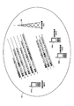
- FIG. 1 is a diagram showing a configuration of a downlink channel used in the communication system according to the first embodiment of the present invention.
- FIG. 2 is a diagram showing a configuration of an uplink channel used in the communication system according to the first embodiment of the present invention.
- the downlink channel shown in FIG. 1 and the uplink channel shown in FIG. 2 are each composed of a logical channel, a transport channel, and a physical channel.
- the logical channel defines the type of data transmission service that is transmitted and received in the medium access control (MAC) layer.
- the transport channel defines what characteristics the data transmitted over the air interface has and how it is transmitted.
- a physical channel is a physical channel that carries a transport channel.
- the downlink logical channel includes broadcast control channel (BCCH: Broadcast Control Channel), paging control channel (PCCH: Paging Control Channel), common control channel (CCCH: Common Control Channel), and dedicated control channel (DCCH: Dedicated Control Channel). ), A dedicated traffic channel (DTCH: Dedicated Traffic Channel), a multicast control channel (MCCH: Multicast Traffic Channel), and a multicast traffic channel (MTCH: Multicast Traffic Channel).
- the uplink logical channels include a common control channel (CCCH), a dedicated control channel (DCCH), and a dedicated traffic channel (DTCH).
- the downlink transport channel includes a broadcast channel (BCH: Broadcast Channel), a paging channel (PCH: Paging Channel), a downlink shared channel (DL-SCH: Downlink Shared Channel), and a multicast channel (MCH: Multicast Channel). included.
- the uplink transport channel includes an uplink shared channel (UL-SCH: Uplink-Shared Channel) and a random access channel (RACH: Random Access Channel).
- the physical downlink channel includes a physical broadcast channel (PBCH: Physical Broadcast Channel), a physical downlink control channel (PDCCH: Physical Downlink Control Channel), a physical downlink shared channel (PDSCH: Physical Downlink Shared Channel), and a physical multicast channel.
- PBCH Physical Broadcast Channel
- PDCCH Physical Downlink Control Channel
- PDSCH Physical Downlink Shared Channel
- PMCH Physical Multicast Channel
- PCFICH Physical Control Format Indicator Channel
- PHICH Physical Hybrid ARQ Indicator Channel
- the uplink physical channel includes a physical uplink shared channel (PUSCH), a physical random access channel (PRACH), and a physical uplink control channel (PUCCH: Physical Uplink Control Channel). It is.
- the broadcast control channel is a downlink channel used for broadcasting system information.
- the paging control channel is a downlink channel used for transmitting paging information, and is used when the network does not know the cell position of the mobile station apparatus.
- the common control channel is a channel used to transmit control information between the mobile station device and the network, and the mobile station device does not have a radio resource control (RRC) connection with the network. Used by.
- RRC radio resource control
- the dedicated control channel is a one-to-one (point-to-point) bidirectional channel and is a channel used for transmitting individual control information between the mobile station apparatus and the network.
- the dedicated control channel is used by a mobile station apparatus having an RRC connection.
- the dedicated traffic channel is a one-to-one bidirectional channel, is a channel dedicated to one mobile station apparatus, and is used for transferring user information (unicast data).
- the multicast control channel is a downlink channel used for transmitting point-to-multipoint MBMS (Multimedia Broadcast Multicast Service) control information from the network to the mobile station apparatus. is there. This is used for MBMS services that provide one-to-many services.
- MBMS Multimedia Broadcast Multicast Service
- MBMS service transmission methods include single-cell point-to-multipoint (SCPTM) transmission and multimedia broadcast multicast service single frequency network (MBSFN) transmission.
- SCPTM single-cell point-to-multipoint
- MBSFN multimedia broadcast multicast service single frequency network
- SCPTM transmission is a method of transmitting an MBMS service by one base station apparatus.
- the multicast control channel is used for one or a plurality of multicast traffic channels (MTCH).
- the multicast traffic channel is a downlink channel used for transmitting traffic data (MBMS transmission data) from the network to the mobile station apparatus in a point-to-multipoint manner.
- multicast control channel MCCH
- MTCH multicast traffic channel
- the paging channel supports DRX and needs to be broadcast to the entire cell.
- the paging channel is mapped to a physical resource that is dynamically used for a traffic channel and other control channels, that is, a physical downlink shared channel (PDSCH).
- PCH paging channel
- PDSCH physical downlink shared channel
- the multicast channel needs to be broadcast to the entire cell.
- quasi-static resource allocation such as MBSFN (MBMS Single Frequency Network) combining (Combining) for MBMS transmission from multiple cells and time frames using extended cyclic prefix (CP) Is supported.
- MBSFN MBMS Single Frequency Network
- CP extended cyclic prefix
- the uplink shared channel (UL-SCH) supports HARQ and dynamic adaptive radio link control.
- beam forming can be used in the uplink shared channel (UL-SCH).
- Dynamic resource allocation and semi-static resource allocation are supported.
- the random access channel (RACH) transmits limited control information and has a collision risk.
- the physical broadcast channel maps the broadcast channel (BCH) at intervals of 40 milliseconds.
- the timing of 40 milliseconds is blind detection. That is, it is not necessary to perform explicit signaling for timing presentation.
- a subframe including a physical broadcast channel (PBCH) can be decoded only by the subframe (self-decodable).
- the physical downlink control channel is downlink shared channel (PDSCH) resource allocation, hybrid automatic repeat request (HARQ) information for downlink data, and uplink that is physical uplink shared channel (PUSCH) resource allocation.
- PDSCH downlink shared channel
- HARQ hybrid automatic repeat request
- PUSCH physical uplink shared channel
- the physical downlink shared channel is a channel used for transmitting downlink data or paging information.
- the physical multicast channel is a channel used for transmitting the multicast channel (MCH), and a downlink reference signal, an uplink reference signal, and a physical downlink synchronization signal are separately arranged.
- the physical uplink shared channel is a channel mainly used for transmitting uplink data (UL-SCH).
- a channel feedback report (downlink channel quality identifier CQI (Channel Quality Indicator), precoding matrix identifier PMI (Precoding Matrix Indicator), rank identifier RI (Rank) Indicator)) and HARQ acknowledgment (ACK: Acknowledgement) / negative acknowledgment (NACK: NegativeNAcknowledgement) for downlink transmission are also transmitted using the physical uplink shared channel (PUSCH).
- CQI Channel Quality Indicator
- PMI Precoding Matrix Indicator
- rank RI rank identifier RI
- HARQ acknowledgment ACK: Acknowledgement
- NACK NegativeNAcknowledgement
- the physical random access channel is a channel used for transmitting a random access preamble and has a guard time.
- the physical uplink control channel (PUCCH) is used to transmit channel feedback reports (CQI, PMI, RI), scheduling requests (SR: Scheduling Request), HARQ for downlink transmission, acknowledgment / negative acknowledgment, etc. Is a channel.
- the physical control format indication channel (PCFICH) is a channel used to notify the mobile station apparatus of the number of OFDM symbols used for the physical downlink control channel (PDCCH), and is transmitted in each subframe.
- the downlink reference signal (DL-RS: Downlink Reference Signal) is a pilot signal transmitted at a predetermined power for each cell.
- the downlink reference signal is a signal that is periodically repeated at a predetermined time interval (for example, one frame), and the mobile station apparatus receives the downlink reference signal at the predetermined time interval and measures the reception quality. Therefore, it is used for judging reception quality for each cell. Further, it is used as a reference signal for demodulating downlink data transmitted simultaneously with the downlink reference signal.
- the sequence used for the downlink reference signal may be an arbitrary sequence as long as it is a sequence that can be uniquely identified for each cell.
- mapping between the transport channel and the physical channel is performed as follows.
- the broadcast channel (BCH) is mapped to the physical broadcast channel (PBCH).
- the multicast channel is mapped to the physical multicast channel (PMCH).
- the paging channel (PCH) and the downlink shared channel (DL-SCH) are mapped to the physical downlink shared channel (PDSCH).
- the physical downlink control channel (PDCCH), the physical hybrid automatic repeat request instruction channel (PHICH), and the physical control format instruction channel (PCFICH) are used alone.
- PDCCH physical downlink control channel
- PHICH physical hybrid automatic repeat request instruction channel
- PCFICH physical control format instruction channel
- the transport channel and the physical channel are mapped as follows.
- the uplink shared channel (UL-SCH) is mapped to the physical uplink shared channel (PUSCH).
- the broadcast control channel is mapped to the broadcast channel (BCH) and the downlink shared channel (DL-SCH).
- the common control channel (CCCH), dedicated control channel (DCCH), and dedicated traffic channel (DTCH) are mapped to the downlink shared channel (DL-SCH).
- mapping from the multicast control channel (MCCH) and the multicast traffic channel (MTCH) to the multicast channel (MCH) is performed at the time of MBSFN transmission, while this mapping is performed at the downlink shared channel (DL-SCH) at the time of SCPTM transmission.
- the logical channel and the transport channel are mapped in the uplink as follows.
- the common control channel (CCCH), dedicated control channel (DCCH), and dedicated traffic channel (DTCH) are mapped to the uplink shared channel (UL-SCH).
- the random access channel (RACH) is not mapped with the logical channel.
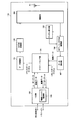
- the OFDM modulation unit 102 receives scheduling information (downlink physical resource block (PRB) allocation information (for example, physical resource block position such as frequency, time, etc.) input from the scheduling unit 104. Information) and a modulation scheme and a coding scheme corresponding to each downlink physical resource block (PRB) (including 16QAM modulation, 2/3 coding rate, etc.), encoding, data modulation, input signal Serial / parallel conversion, IFFT (Inverse Fourier Transform) processing, cyclic prefix (CP) insertion, and OFDM signal processing such as filtering are performed to generate an OFDM signal and to the radio section 103 Output.
- scheduling information downlink physical resource block (PRB) allocation information (for example, physical resource block position such as frequency, time, etc.) input from the scheduling unit 104.
- PRB physical resource block
- Information for example, physical resource block position such as frequency, time, etc.
- a modulation scheme and a coding scheme corresponding to each downlink physical resource block (PRB) including 16QA
- the radio unit 103 up-converts the modulation data input from the OFDM modulation unit 102 to a radio frequency to generate a radio signal, and transmits the radio signal to the mobile station apparatus 200 via the antenna unit A1.
- Radio section 103 receives an uplink radio signal from mobile station apparatus 200 via antenna section A1, down-converts it to a baseband signal, and receives received data from channel estimation section 105 and DFT-S- Output to the OFDM demodulator 106.
- the scheduling unit 104 performs processing of a medium access control (MAC: Medium Access Control) layer.
- the scheduling unit 104 performs mapping between logical channels and transport channels, downlink and uplink scheduling (HARQ processing, selection of transport format, etc.) and the like. Since the scheduling unit 104 controls the processing units of each physical layer in an integrated manner, the scheduling unit 104, the antenna unit A1, the radio unit 103, the channel estimation unit 105, the DFT-S-OFDM demodulation unit 106, and the data control unit 101 There is an interface between the OFDM modulation unit 102 and the data extraction unit 107. However, not shown.
- MAC Medium Access Control
- scheduling section 104 receives feedback information received from mobile station apparatus 200 (downlink channel feedback report (channel quality (CQI), number of streams (RI), precoding information (PMI), etc.)). Or ACK / NACK feedback information for downlink data), downlink physical resource block (PRB) information that can be used by each mobile station device, buffer status, scheduling information input from higher layer 108, etc. Selection processing of downlink transport format (transmission form) for modulating each data (physical resource block (PRB) allocation, modulation scheme and encoding scheme, etc.), retransmission control in HARQ, and downlink And generates the scheduling information used for scheduling.
- the scheduling information used for downlink scheduling is output to the data control unit 101 and the data extraction unit 107.
- the scheduling unit 104 estimates the uplink channel state (radio channel state) output from the channel estimation unit 105, the resource allocation request from the mobile station device 200, and each mobile station device 200. Based on the downlink physical resource block (PRB) information that can be used, the scheduling information input from the higher layer 108, etc., and the uplink transport format (transmission form) for modulating each data (physical resource block) (PRB) allocation, modulation scheme, encoding scheme, etc.) selection processing and scheduling information used for uplink scheduling are generated.
- PRB physical resource block
- the scheduling information used for uplink scheduling is output to the data control unit 101 and the data extraction unit 107.
- the scheduling unit 104 maps the downlink logical channel input from the higher layer 108 to the transport channel, and outputs it to the data control unit 101.
- the scheduling unit 104 processes the control data and the transport channel acquired in the uplink input from the data extraction unit 107 as necessary, maps them to the uplink logical channel, and outputs them to the upper layer 108. To do.
- the channel estimation unit 105 estimates an uplink channel state from an uplink demodulation reference signal (DRS: Demodulation Reference Signal) for demodulation of the uplink data, and the estimation result is used as a DFT-S-OFDM demodulation unit 106. Output to. Further, in order to perform uplink scheduling, an uplink channel state is estimated from an uplink measurement reference signal (SRS: Sounding Reference Signal), and the estimation result is output to the scheduling section 104.
- DRS Demodulation Reference Signal
- the DFT-S-OFDM demodulation unit 106 performs DFT (Discrete Fourier Transform: Discrete Fourier Transform) on the modulated data input from the radio unit 103 based on the uplink channel state estimation result input from the channel estimation unit 105. ) Perform DFT-S-OFDM signal processing such as conversion, subcarrier mapping, IFFT conversion, filtering, etc., perform demodulation processing, and output to the data extraction unit 107.
- DFT Discrete Fourier Transform: Discrete Fourier Transform
- the data extraction unit 107 confirms the correctness / incorrectness of the data input from the DFT-S-OFDM demodulation unit 106 and confirms the confirmation result (positive signal ACK / negative signal NACK). ) Is output to the scheduling unit 104.
- the separated control data includes feedback information (downlink channel feedback report (CQI, PMI, RI), ACK / NACK feedback information for downlink data) notified from the mobile station apparatus 200, and the like. .
- feedback information downlink channel feedback report (CQI, PMI, RI), ACK / NACK feedback information for downlink data
- the upper layer 108 performs processing of a packet data integration protocol (PDCP: Packet Data Convergence Protocol) layer, a radio link control (RLC: Radio Link Control) layer, and a radio resource control (RRC: Radio Resource Control) layer.
- PDCP Packet Data Convergence Protocol
- RLC Radio Link Control
- RRC Radio Resource Control
- the upper layer 108 integrates and controls the processing units of the lower layer, so the upper layer 108, the scheduling unit 104, the antenna unit A1, the radio unit 103, the channel estimation unit 105, the DFT-S-OFDM demodulation unit 106, the data
- PDCP Packet Data Convergence Protocol
- RLC Radio Link Control
- RRC Radio Resource Control
- the upper layer 108 has a radio resource control unit 109.
- the radio resource control unit 109 also manages various setting information, system information, measurement settings and measurement results, paging control, communication state management of each mobile station apparatus, mobility management such as handover, mobile station Management of buffer status for each device, management of unicast and multicast bearer connection settings, management of mobile station identifier (UEID), and the like are performed.
- the upper layer 108 transmits / receives information to another base station apparatus and information to an upper node.
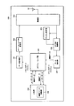
- FIG. 5 is a schematic block diagram showing the configuration of the mobile station apparatus 200 according to the first embodiment of the present invention.
- the mobile station apparatus 200 includes a data control unit 201, a DFT-S-OFDM modulation unit 202, a radio unit 203, a scheduling unit 204, a channel estimation unit 205, an OFDM demodulation unit 206, a data extraction unit 207, an upper layer 208, and an antenna unit A2. It has.
- the data control unit 201, the DFT-S-OFDM modulation unit 202, the radio unit 203, the scheduling unit 204, the upper layer 208, and the antenna unit A2 constitute a transmission unit.
- Radio section 203, scheduling section 204, channel estimation section 205, OFDM demodulation section 206, data extraction section 207, upper layer 208, and antenna section A2 constitute a reception section.
- the scheduling unit 204 constitutes a selection unit.
- the antenna unit A2, the data control unit 201, the DFT-S-OFDM modulation unit 202, and the radio unit 203 perform uplink physical layer processing.
- the antenna unit A2, the radio unit 203, the channel estimation unit 205, the OFDM demodulation unit 206, and the data extraction unit 207 perform downlink physical layer processing.
- a part of each transmission unit and reception unit is configured to perform processing separately for each component carrier, and a part is configured to perform common processing between component carriers.
- the data control unit 201 acquires a transport channel from the scheduling unit 204.
- the data control unit 201 converts the transport channel and the signal and channel generated in the physical layer based on the scheduling information input from the scheduling unit 104 to the physical channel based on the scheduling information input from the scheduling unit 204. Map. Each piece of data mapped in this way is output to the DFT-S-OFDM modulation unit 202.
- the DFT-S-OFDM modulation unit 202 performs data modulation, DFT processing, subcarrier mapping, inverse fast Fourier transform (IFFT) processing, cyclic prefix (CP) insertion, filtering on the data input from the data control unit 201.
- DFT-S-OFDM signal processing such as the above is performed to generate a DFT-S-OFDM signal and output it to the radio section 203.
- the uplink communication scheme is assumed to be a single carrier scheme such as DFT-S-OFDM, but a multicarrier scheme such as the OFDM scheme may be used instead.
- Radio section 203 up-converts the modulation data input from DFT-S-OFDM modulation section 202 to a radio frequency, generates a radio signal, and transmits the radio signal to base station apparatus 100 via antenna section A2.
- Radio section 203 receives a radio signal modulated with downlink data from base station apparatus 100 via antenna section A2, down-converts it into a baseband signal, and converts the received data into a channel estimation section. 205 and output to OFDM demodulator 206.
- the scheduling unit 204 performs processing of the medium access control layer.
- the scheduling unit 104 performs mapping between logical channels and transport channels, downlink and uplink scheduling (HARQ processing, selection of transport format, etc.) and the like. Since the scheduling unit 104 controls the processing units of each physical layer in an integrated manner, the scheduling unit 104, the antenna unit A2, the data control unit 201, the DFT-S-OFDM modulation unit 202, the channel estimation unit 205, the OFDM demodulation unit 206, an interface between the data extraction unit 207 and the wireless unit 203 exists. However, not shown.
- the scheduling unit 204 controls reception of transport channels, physical signals, and physical channels based on scheduling information (transport format and HARQ retransmission information) from the base station apparatus 100 and the upper layer 208, and the like. Scheduling information used for HARQ retransmission control and downlink scheduling is generated. The scheduling information used for downlink scheduling is output to the data control unit 201 and the data extraction unit 207.
- the scheduling unit 204 receives the uplink buffer status input from the higher layer 208 and uplink scheduling information from the base station apparatus 100 input from the data extraction unit 207 (transport format and HARQ retransmission). Information), and scheduling processing for mapping the uplink logical channel input from the upper layer 208 to the transport channel and the uplink scheduling based on the scheduling information input from the upper layer 208, etc. Scheduling information to be generated is generated.
- the scheduling information is output to the data control unit 201 and the data extraction unit 207.
- the scheduling unit 204 maps the uplink logical channel input from the higher layer 208 to the transport channel, and outputs it to the data control unit 201.
- the scheduling unit 204 also outputs the downlink channel feedback report (CQI, PMI, RI) input from the channel estimation unit 205 and the CRC confirmation result input from the data extraction unit 207 to the data control unit 201. To do.
- the scheduling unit 204 processes the control data and the transport channel acquired in the downlink input from the data extraction unit 207 as necessary, maps them to the downlink logical channel, and outputs them to the upper layer 208. To do.
- the channel estimation unit 205 estimates the downlink channel state from the downlink reference signal (RS) and demodulates the downlink data, and outputs the estimation result to the OFDM demodulation unit 206.
- RS downlink reference signal
- the channel estimation unit 205 estimates the downlink channel state from the downlink reference signal (RS) in order to notify the base station apparatus 100 of the estimation result of the downlink channel state (radio channel state), This estimation result is converted into a downlink channel feedback report (channel quality information or the like) and output to the scheduling section 204. Further, in order to notify the base station apparatus 100 of the downlink measurement result, the downlink reference signal (RS) measurement result is output to the radio resource control unit 209.
- RS downlink reference signal
- OFDM demodulation section 206 Based on the downlink channel state estimation result input from channel estimation section 205, OFDM demodulation section 206 performs OFDM demodulation processing on the modulated data input from radio section 203 and outputs the result to data extraction section 207. To do.
- the data extraction unit 207 performs cyclic redundancy check (CRC) on the data input from the OFDM demodulation unit 206 to confirm correctness and output a confirmation result (ACK / NACK feedback information) to the scheduling unit 204.
- CRC cyclic redundancy check
- the data extraction unit 207 separates the data input from the OFDM demodulation unit 206 into transport channel and physical layer control data based on the scheduling information from the scheduling unit 204, and outputs the data to the scheduling unit 204.
- the separated control data includes scheduling information such as downlink or uplink resource allocation and uplink HARQ control information.
- the search space (also referred to as a search region) of the physical downlink control signal (PDCCH) is decoded to extract downlink or uplink resource allocations addressed to the own station.
- the upper layer 208 performs processing of a packet data integration protocol (PDCP: Packet Data Convergence Protocol) layer, a radio link control (RLC: Radio Link Control) layer, and a radio resource control (RRC: Radio Resource Control) layer.
- PDCP Packet Data Convergence Protocol
- RLC Radio Link Control
- RRC Radio Resource Control
- the upper layer 208 has a radio resource control unit 209.
- the upper layer 208 integrates and controls the processing units of the lower layer, so that the upper layer 208, the scheduling unit 204, the antenna unit A2, the data control unit 201, the DFT-S-OFDM modulation unit 202, the channel estimation unit 205, There is an interface between the OFDM demodulator 206, the data extractor 207, and the radio unit 203. However, not shown.
- the radio resource control unit 209 manages various setting information, system information, measurement settings and measurement results, paging control, management of the communication state of the local station, mobility management such as handover, buffer status management, It manages the connection settings for cast and multicast bearers and manages the mobile station identifier (UEID).
- UEID mobile station identifier
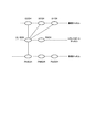
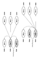
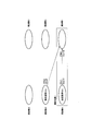
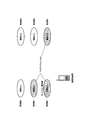
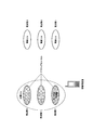
- FIG. 3 is a diagram showing an example of the network configuration of the present invention.
- the mobile station apparatus 200 can simultaneously communicate with a plurality of frequency layers (component carrier CC1 to component carrier CC3) by carrier aggregation, as a network configuration, one base station apparatus 1002 has a plurality of downlink frequency layers.
- each has a transmission unit 21 and a transmission unit 22 (CC2 to CC3), and one base station apparatus 1001 has one transmission unit 11 for each frequency layer (CC1).
- CC1 frequency layer
- the transmission part 21 and the transmission part 22 may be comprised by one transmission part.
- one base station apparatus includes a receiving unit for each of a plurality of uplink frequency layers, and one base station apparatus includes one receiving unit for each frequency layer. In some cases, both of them may be mixed.
- base station apparatuses 1001 and 1002 may be managed by host control station 300, or may be cooperatively controlled between base station apparatus 1001 and base station apparatus 1002.
- the mobile station apparatus 200 recognizes as a cell without particular awareness of which base station apparatus the downlink component carrier is transmitted from and which base station apparatus receives the uplink component carrier.
- System information such as the frequency band and bandwidth of the corresponding uplink component carrier is acquired from the system information broadcast in each cell. Since component carriers are added (carrier aggregation) to the mobile station apparatus 200 using dedicated signals (RRC signaling or the like), it is possible to set component carriers specific to the mobile station apparatus.
- the mobile station device manages a system information element (IE: Information Element) composed of a system information field that is each content of system information and one or a plurality of system information fields. These system information (including system information fields and system information elements) are managed for each component carrier by RRC of the mobile station apparatus and the base station apparatus.
- the system information is a setting information parameter managed by a system that performs communication between the mobile station apparatus and the base station apparatus, and is also a parameter necessary for the mobile station apparatus to operate in the system.
- the system information includes measurement settings (Measurement configuration), measurement identifiers (measId), measurement objects (Measurement objects), reporting settings (Reporting configurations), and the like.
- the system information managed by RRC is notified from the base station apparatus to the mobile station apparatus through the broadcast control channel (BCCH) or by RRC signaling of the common control channel (CCCH) and / or the dedicated control channel (DCCH).
- BCCH broadcast control channel
- CCCH common control channel
- DCCH dedicated control channel
- the system information managed by this RRC is managed as a parameter that is different for each component carrier (specific to each component carrier).
- a new RRC message type that designates a component carrier identification number and notifies system information may be prepared for each system information, or RRC connection reconfiguration ( RRCConnectionReconfiguration) message may be extended so that the RRC connection reconfiguration message can be notified by specifying the identification number of the component carrier.
- RRC connection reconfiguration RRCConnectionReconfiguration
- a physical cell identifier physicalCellIdentity
- a target frequency may be used as the component carrier identification number.
- SIB SystemInformationBlock
- BCCH broadcast control channel
- the mobile station apparatus manages system information of one or a plurality of component carriers having a partial bandwidth in the system band, and when a component carrier is added to the mobile station apparatus, the component carrier currently being accessed This system information is also applied to each added component carrier.
- the mobile station device does not notify the system information that is not notified as system information applied to the added component carrier.
- System information is applied to each added component carrier.
- the mobile station device transmits the system information of the currently accessed component carrier to each added component carrier. Apply.
- the mobile station device transmits system information of a default value (initial value) to each added component carrier. Apply.
- carrier aggregation can also be interpreted as a concept of adding an active component carrier (cell) or activating a component carrier (cell).
- This active component carrier (cell) is called an active set cell (Active (Set Cells) or an active set component carrier (Active Set Component Carriers).
- This active set cell includes cells (or component carriers) of the same and different frequency layers.
- the mobile station apparatus 200 that has acquired the information related to component carrier addition adjusts the radio unit 203 so that the added component carrier can be received.
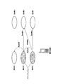
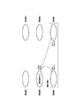
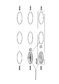
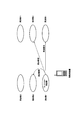
- Interpretation of serving cell 1 One example of the concept of the serving cell (interpretation 1 of the serving cell) will be described with reference to FIG.
- the mobile station apparatus and the base station apparatus interpret each active component carrier as a serving cell.
- An adjacent cell is a cell other than the serving cell when one cell in a certain active set cell is considered as the serving cell. That is, a cell in the active set may be interpreted as a neighbor cell depending on which cell is considered to be a serving cell. In this way, since the concept of the serving cell is expanded, it is possible to efficiently perform settings related to measurement of a plurality of frequency layers. Moreover, the measurement between the cells in the active set can be interpreted as the measurement between the serving cell and the adjacent cell. In addition, it is possible to apply the setting of the serving cell and the neighboring cell set in each cell as they are.
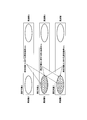
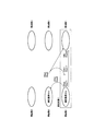
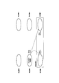
- Interpreted cell 2 Another example of the concept of the serving cell (interpretation cell interpretation 2) will be described with reference to FIG.
- the mobile station apparatus and the base station apparatus interpret all active component carriers as serving cells. Neighboring cells are cells that are not set as active set cells. In this way, since the concept of the serving cell is expanded, it is possible to efficiently perform settings related to measurement of a plurality of frequency layers. In addition, cells in the active set can be omitted from neighboring cells to be measured at the time of measurement. In addition, it is possible to apply the setting of the serving cell and the neighboring cell set in each cell as they are.
- Intra-frequency measurements are measurements at the downlink frequency of each cell set as an active set cell.
- Inter-frequency measurements are measurements at a frequency different from the downlink frequency of each cell set in the active set cell. In other words, if a cell to be measured as a serving cell is one cell in the active set cell, measurement between the serving cell to be measured in the active set cell and a cell having a different frequency in the active set cell is performed between the frequencies. It becomes measurement. Thereby, the base station apparatus and the mobile station apparatus can automatically manage the inter-frequency measurement and the intra-frequency measurement according to the setting of the active set cell.
- the identification number of the component carrier may be specified so that the measurement objects (Measurement objects) are set for each cell (component carrier).
- the measurement object identifier (measObjectId) is distinguished for each cell (component carrier).
- the mobile station apparatus and the base station apparatus identify the measurement object (Measurement objects) by specifying the measurement object identifier (measObjectId) or the component carrier identification number and the measurement object identifier (measObjectId) that include the component carrier identification number as an information element. To do.
- This setting is applicable to both the interpretation 1 of the serving cell and the interpretation 2 of the serving cell.
- the serving cell (measurement reference cell (target cell of the measurement result Ms)) for the measurement object (Measurement objects) is the designated cell (component carrier).
- reporting settings specify the component carrier identification number (cell identification number in the active set cell), and the measurement reference cell (target of the measurement result Ms)
- a reporting configuration may be set for each component carrier interpreted as a cell.
- the mobile station device and the base station device identify the report configuration identifier (reporting configuration) by specifying the report configuration identifier (reportConfigId) or the component carrier identification number and the report configuration identifier (reportConfigId) that include the component carrier identification number as an information element. To do.
- the mobile station apparatus and the base station apparatus interpret the reporting settings (Reporting configurations) using the designated cell (component carrier) as the measurement reference cell (target cell of the measurement result Ms). This setting is applicable to both the interpretation 1 of the serving cell and the interpretation 2 of the serving cell.
- the measurement identifier (measId) a common value can be used without being distinguished for each component carrier. This setting is applicable to both the interpretation 1 of the serving cell and the interpretation 2 of the serving cell.
- the measurement identifier (measId) has a plurality of serving cells to be measured. Therefore, specify the identification number of the component carrier (cell identification number in the active set cell) and the measurement reference cell (target cell of the measurement result Ms) ) So that the measurement identifier (measId) is set for each component carrier.
- the measurement reference cell (the target cell of the measurement result Ms) is a cell (component carrier) serving as a reference for the measurement object (Measurement objects) when performing the measurement (Measurement). That is, it is a serving cell in a measurement object.
- the measurement reference cell (the target cell of the measurement result Ms) is the identification number (active set) of the component carrier specified by the measurement identifier (measId), the measurement target (Measurement objects), or the reporting configuration (Reporting configuration). There is a method of identifying by a cell identification number in a cell.
- the measurement reference cell (the target cell of the measurement result Ms) is a cell (component carrier) serving as a reference for the measurement object (Measurement objects) when performing measurement. That is, it is a serving cell in a measurement object.
- the measurement reference cell is a cell (component carrier) serving as a reference for the measurement object (Measurement objects) when performing measurement. That is, it is a serving cell in a measurement object.
- all or a plurality of in-zone cells described in the interpretation of in-zone cell 2 are set as measurement reference cells (target cells of measurement result Ms) (all or a plurality of cells in the active set cell). Is a measurement reference cell (target cell of the measurement result Ms). That is, it provides a plurality of measurement reference cells (target cells of the measurement result Ms).
- report results for a plurality of measurement reference cells are reported from the mobile station apparatus.
- target cells of the measurement result Ms When setting multiple metric cells independently from the active set cell, you can set multiple metric cells (measId), measurement objects, or reporting configurations (Reporting configurations)
- the target cell of the measurement result Ms) is designated.
- the measurement reference cell When a plurality of measurement reference cells are all cells of the active set cell, the measurement reference cell (target cell of the measurement result Ms) is determined according to the setting of the active set cell.
- the base station apparatus notifies the serving cell quality threshold (s-Measure)
- the mobile station apparatus determines that the quality (RSRP value) of the measurement reference cell (target cell of the measurement result Ms) is the serving cell quality threshold (s-Measure).
- measurement of neighboring cells and event evaluation whether or not event trigger conditions are satisfied, also referred to as reporting criteria evaluation) are performed.
- the base station device does not notify the cell quality threshold (s-Measure)
- the mobile station device does not depend on the quality (RSRP value) of the neighboring cell regardless of the quality (RSRP value) of the measurement reference cell (target cell of the measurement result Ms). Perform measurement and event evaluation.
- Ms is a measurement result for a cell (component carrier) designated as a measurement reference cell.
- Mn is a measurement result for a cell (component carrier) that is not designated as a measurement reference cell in measurement objects (Measurement objects).
- Ofn is a frequency-specific measurement offset value for the frequency of a cell (component carrier) not designated as a measurement reference cell.
- Ofn is the same as Ofs.
- offsetFreq an offset frequency included in a measurement target EUTRA (measObjectEUTRA) corresponding to a downlink frequency different from the measurement reference cell.
- Ocn is a cell-specific measurement offset value for the frequency of a cell (component carrier) not designated as a measurement reference cell.
- Ocn is a cell-specific offset (cellIndividualOffset) included in the measurement target EUTRA (measObjectEUTRA) having the same downlink frequency as the measurement reference cell.
- Ocn is a cell-specific offset (cellIndividualOffset) included in a measurement target EUTRA (measObjectEUTRA) corresponding to a downlink frequency different from the measurement reference cell.
- Ocs is a cell-specific measurement offset value of the measurement reference cell.
- the mobile station measures the measurement result Ms (event A1, A2) of the measurement reference cell, or the measurement result Ms of the measurement reference cell and the measurement result Mn (event A3, A5) of the cell (component carrier) not designated as the measurement reference cell.
- each event is generated based on a measurement result Mn (event A4) of a cell (component carrier) not designated as a measurement reference cell.
- the interpretation 1 of the event trigger condition is preferably applied to the interpretation 1 of the serving cell and the interpretation 1 of the measurement reference cell.
- Ms is a measurement result for a cell (component carrier) designated as a measurement reference cell.
- Mn is a measurement result for a cell (component carrier) that is not included in the active set cell in the measurement objects.
- the mobile station uses the measurement result Ms (event A1, A2) of the measurement reference cell, or the measurement result Ms of the measurement reference cell and the measurement result Mn (event A3, A5) of the cell (component carrier) not included in the active set cell, Alternatively, each event is generated based on a measurement result Mn (event A4) of a cell (component carrier) not included in the active set cell. In this case, an event between cells in the active set cell will not be a trigger target.
- the interpretation 2 of the event trigger condition is preferably applied to the interpretation 2 of the serving cell and the interpretation 1 of the measurement reference cell.
- Ocn is a cell-specific measurement offset value for the frequency of the target cell of Mn.
- Ocn is a cell-specific offset (cellIndividualOffset) included in the measurement target EUTRA (measObjectEUTRA) having the same downlink frequency as each measurement reference cell.
- Ocn is a cell-specific offset (cellIndividualOffset) included in a measurement target EUTRA (measObjectEUTRA) corresponding to a downlink frequency different from each measurement reference cell.
- the mobile station measures the measurement result Ms (event A1, A2) of each measurement reference cell, or the measurement result Ms of each measurement reference cell and the measurement result of each measurement reference cell (target cell of the measurement result Ms).
- Measurement results Mn (event A3, A5) of cells (component carriers) other than measurement reference cells, or cells (components) other than the measurement reference cells at the time of measurement for each measurement reference cell (target cell of measurement results Ms)
- Each event is generated by the measurement result Mn (event A4) of (carrier).
- the interpretation 3 of the event trigger condition is preferably applied to the interpretation 1 of the serving cell and the interpretation 2 of the measurement reference cell.
- Ms is a measurement result for each of all or a plurality of measurement reference cells (component carriers) in the active set as described in the interpretation 2 of measurement reference cells.
- Mn is a measurement result for a cell (component carrier) other than a cell set as a measurement reference cell (a target cell of the measurement result Ms) in the measurement object (MeasurementMeasureobjects).
- the mobile station measures the measurement result Ms (event A1, A2) of the measurement reference cell, or the measurement result Ms of the measurement reference cell and the measurement result Mn (event A3, A5) of the cell (component carrier) not designated as the measurement reference cell.
- each event is generated based on a measurement result Mn (event A4) of a cell (component carrier) not designated as a measurement reference cell.
- an event between cells set as a measurement reference cell (a target cell of the measurement result Ms) is not a trigger target.
- the interpretation 3 of the event trigger condition is preferably applied to the interpretation 2 of the serving cell and the interpretation 2 of the measurement reference cell.
- the measurement result is reported by the following method (measurement result method 1) when a plurality of measurement reference cells are specified for the measurement identifier (measId).
- the base station device can grasp the status of all cells (or all cells of the active set cell) set as measurement reference cells from the mobile station device without any special designation. It becomes possible to infer the cause of each event.
- the measurement result is reported as follows when a plurality of measurement reference cells are designated for the measurement identifier (measId). .
- the mobile station device determines the optimum cell from the results of the reference signal reception power (RSRP) and / or reference signal reception quality (RSRQ) of all cells (or all cells of the active set cell) set as the measurement reference cell.
- In-cell measurement result includes optimal carrier component carrier identification number (cell identification number in active set cell), optimal cell reference signal received power (RSRP) and / or reference signal reception quality (RSRQ) To report.
- the only reported events are those with the optimal cell as the measurement cell.
- the frequency of each frequency may be compared with the value after the addition of the Ocs of each measurement reference cell with respect to each measurement reference cell. By doing in this way, it becomes possible for a base station apparatus to operate the report priority between component carriers.
- An event identifier may be assigned as a separate event with a measurement report (measurement report) for the optimal cell among all cells (or all cells in the active set cell) set as the measurement reference cell. . That is, for each measurement reference cell, the report is triggered when the optimum cell (component carrier) is changed in consideration of Ofs of each frequency and Ocs of each measurement reference cell.
- a method of processing system information related to measurement when an active set cell (component carrier) is added or deleted will be described.
- the measurement identifier (measId) linked to the measurement target identifier (measObjectId) corresponding to the carrier frequency of the added cell is deleted
- Measurement identifier linked to the measurement identifier (measObjectId) linked to the measurement target identifier (measObjectId) corresponding to the carrier frequency of the cell and linked to the measurement target identifier (measObjectId) corresponding to the carrier frequency of the deleted cell MeasId
- MeasId is linked to the measurement identifier (measId) linked to the measurement target identifier (measObjectId) corresponding to the carrier frequency of the added cell.
- the DL master frequency (also referred to as downlink primary component carrier or downlink primary cell) is a downlink frequency layer (component carrier or component carrier group) that is first accessed or monitored by the mobile station apparatus, or a base station It may be a specific downlink frequency layer determined by designation from the device.
- a downlink synchronization signal (SCH) that can acquire at least downlink synchronization is arranged.
- the DL slave frequency (also referred to as a downlink secondary component carrier or downlink secondary cell) is a downlink frequency layer that is not designated as a DL master frequency among accessible component carriers designated by the base station apparatus. .
- the UL master frequency (also referred to as an uplink primary component carrier) is an uplink frequency layer (component carrier or component carrier group) that a mobile station apparatus accesses first, or is designated by a DL master frequency, or , A component carrier or a component carrier group associated with the DL master frequency, or a specific uplink frequency layer determined by designation from the base station apparatus.
- the UL slave frequency (also referred to as an uplink secondary component carrier) is an uplink frequency layer that is not designated as the UL master frequency among accessible component carriers designated by the base station apparatus.
- the master frequency and slave frequency for each mobile station device may be different. That is, the master frequency for a certain mobile station apparatus may be configured to be the slave frequency for another mobile station apparatus. This indicates that the component carrier is added to the mobile station device using a dedicated signal, and therefore, the component carrier specific to the mobile station device can be set.
- the master frequency and the slave frequency may be arranged in adjacent carrier frequencies or may be arranged in separated carrier frequencies.
- a master frequency may be provided for each function.
- the master frequency related to measurement will be described.
- the mobile station device manages a system information element (IE: Information Element) composed of a system information field that is each content of system information and one or a plurality of system information fields. These system information (including system information fields and system information elements) are managed for each component carrier by RRC of the mobile station apparatus and the base station apparatus.
- the system information is a setting information parameter managed by a system that performs communication between the mobile station apparatus and the base station apparatus, and is also a parameter necessary for the mobile station apparatus to operate in the system.
- the system information includes measurement settings (Measurement configuration), measurement identifiers (measId), measurement objects (Measurement objects), reporting settings (Reporting configurations), and the like.
- the system information managed by RRC is notified from the base station apparatus to the mobile station apparatus through the broadcast control channel (BCCH) or by RRC signaling of the common control channel (CCCH) and / or the dedicated control channel (DCCH).
- BCCH broadcast control channel
- CCCH common control channel
- DCCH dedicated control channel
- the mobile station device and the base station device apply and manage the system information used at the master frequency to each component carrier.
- the mobile station device and the base station device interpret the DL master frequency as serving cells.
- the adjacent cell is a cell other than the DL master frequency.
- An adjacent cell is a cell other than the serving cell when one cell in a certain active set cell is considered as the serving cell. That is, a cell in the active set may be interpreted as a neighbor cell depending on which cell is considered to be a serving cell. In this way, since the concept of the serving cell is expanded, it is possible to efficiently perform settings related to measurement of a plurality of frequency layers. In addition, it is possible to perform measurement based on one cell.
- the mobile station apparatus and the base station apparatus interpret the DL master frequency in the serving cell as a measurement reference cell.
- the serving cell is composed of a plurality of component carriers including the DL master frequency.
- An adjacent cell is a cell other than a serving cell composed of a plurality of component carriers including a DL master frequency.
- Intra-frequency measurements are measurements at the DL master frequency downlink frequency.
- Inter-frequency measurements are measurements at a frequency different from the DL master frequency downlink frequency.
- Measurement objects As the measurement object identifier (measObjectId), a common value can be used without being distinguished for each component carrier.
- ReportConfigId As the report configuration identifier (reportConfigId), a common value can be used without being distinguished for each component carrier.
- the measurement identifier (measId) a common value can be used without being distinguished for each component carrier.
- Ms is the measurement result for the DL master frequency.
- Mn is a measurement result for a cell (component carrier) not designated as the DL master frequency.
- Ofn is a frequency-specific measurement offset value for the frequency of a cell (component carrier) not designated as the DL master frequency.
- Ofn is the same as Ofs.
- offsetFreq an offset frequency included in a measurement target EUTRA (measObjectEUTRA) corresponding to a downlink frequency different from the DL master frequency.
- Ocn is a cell-specific measurement offset value for the frequency of a cell (component carrier) not designated as the DL master frequency.
- Ocn is a cell-specific offset (cellIndividualOffset) included in the measurement target EUTRA (measObjectEUTRA) having the same downlink frequency as the DL master frequency.
- Ocn is a cell-specific offset (cellIndividualOffset) included in a measurement target EUTRA (measObjectEUTRA) corresponding to a downlink frequency different from the DL master frequency.
- Ocs is a cell-specific measurement offset value of the DL master frequency.
- the mobile station generates each event based on the measurement result Ms of the DL master frequency and the measurement result Mn of the cell (component carrier) not designated as the DL master frequency.
- control can be facilitated by unifying measurement parameter settings at the DL master frequency.
- Measurement identifier (measId) linked to the measurement identifier (measObjectId) linked to the corresponding measurement target identifier (measObjectId) and linked to the measurement target identifier (measObjectId) corresponding to the carrier frequency of the original DL master frequency Are linked to the measurement identifier (measId) linked to the measurement target identifier (measObjectId) corresponding to the carrier frequency of the DL master frequency to be changed.
- the component carrier can be interpreted simply as a cell, and the mobile station apparatus can also be interpreted as managing system information of a plurality of cells.
- RRC signaling is not an addition of a component carrier, but an addition of an active (activated) cell or an activation of a cell.
- Communicating with multiple component carriers is interpreted as communicating with multiple active cells. It can also be interpreted that a plurality of component carriers are managed in one cell.
- the mobile station device is not limited to a moving terminal, and may be realized by mounting the function of the mobile station device on a base station device or a fixed terminal.
- each function in the base station apparatus and a program for realizing each function in the mobile station apparatus are recorded on a computer-readable recording medium and recorded on this recording medium.
- the base station apparatus or mobile station apparatus may be controlled by causing the computer system to read and execute the program.
- the “computer system” includes an OS and hardware such as peripheral devices.
- the “computer-readable recording medium” means a storage device such as a flexible disk, a magneto-optical disk, a portable medium such as a ROM and a CD-ROM, and a hard disk incorporated in a computer system.
- a “computer-readable recording medium” means that a program is dynamically held for a short time, like a communication line when a program is transmitted via a network such as the Internet or a communication line such as a telephone line. In this case, it is intended to include those that hold a program for a certain period of time, such as a volatile memory inside a computer system serving as a server or a client in that case.
- the program may be for realizing a part of the above-described functions, and may be capable of realizing the above-described functions in combination with a program already recorded in the computer system. .
- DESCRIPTION OF SYMBOLS 100 Base station apparatus, 101 ... Data control part, 102 ... OFDM modulation part, 103 ... Radio
Landscapes
- Engineering & Computer Science (AREA)
- Signal Processing (AREA)
- Computer Networks & Wireless Communication (AREA)
- Quality & Reliability (AREA)
- Physics & Mathematics (AREA)
- Electromagnetism (AREA)
- Mobile Radio Communication Systems (AREA)
Abstract
Description
次に、測定(measurement)について、説明を行う。基地局装置は、移動局装置に対して、RRCシグナリング(無線リソース制御信号)のRRC接続再設定(RRCConnectionReconfiguration)メッセージを使って、測定設定(Measurement configuration)メッセージを送信する。移動局装置は、測定設定(Measurement configuration)メッセージに含まれるシステム情報を設定するとともに、通知されたシステム情報に従って、在圏セル(serving cell)および隣接セル(リストセル(listed cell)および/または検出セル(detected cell)を含む)に対する測定、イベント評価、測定報告を行う。リストセルは、測定対象(Measurement object)にリストされているセル(基地局装置から移動局装置へ隣接セルリストとして通知されているセル)であり、検出セルは、測定対象(Measurement object)によって指示された周波数において移動局装置が検出したが、測定対象(Measurement object)にはリストされていないセル(隣接セルリストとして通知されていない移動局装置自身が検出したセル)である。
数量設定(quantityConfig)は、測定対象(Measurement objects)がEUTRAの場合、第3層フィルタ係数(L3 filtering coefficient)を指定する。第3層フィルタ係数(L3 filtering coefficient)は、最新の測定結果と、過去のフィルタリング測定結果との比(割合)を規定する。フィルタリング結果は、移動局装置でイベント評価に利用される。
測定ギャップ設定(measGapConfig)は、測定ギャップパターン(measurement gap pattern)の設定や、測定ギャップ(measurement gap)の活性化(activation)/非活性化(deactivation)を制御するために利用される。測定ギャップ設定(measGapConfig)では、測定ギャップを活性化させる場合の情報として、ギャップパターン(gap pattern)、開始システムフレーム番号(startSFN)、開始サブフレーム番号(startSubframeNumber)が通知される。ギャップパターン(gap pattern)は、測定ギャップ(measurement gap)として、どのパターンを使うかを規定する。開始システムフレーム番号(startSFN)は、測定ギャップ(measurement gap)を開始するSFN(System Frame Number)を規定する。開始サブフレーム番号(startSubframeNumber)は、測定ギャップ(measurement gap)を開始するサブフレーム番号を規定する。
在圏セル品質スレッショルド(s-Measure)は、在圏セル(serving cell)の品質に関するスレッショルドを表し、移動局装置が測定(measurement)を行う必要があるか否かを制御するために利用される。在圏セル品質スレッショルド(s-Measure)は、参照信号受信電力(RSRP)に対する値として設定される。
ここで、測定識別子(measId)は、測定対象(Measurement objects)と、報告設定(Reporting configurations)とをリンクさせるために利用され、具体的には、測定対象識別子(measObjectId)と報告設定識別子(reportConfigId)とをリンクさせる。測定識別子(measId)には、一つの測定対象識別子(measObjectId)と一つの報告設定識別子(reportConfigId)が対応付けられる。測定設定(Measurement configuration)メッセージは、測定識別子(measId)、測定対象(Measurement objects)、報告設定(Reporting configurations)の関係に対して追加・修正・削除することが可能である。
れた測定対象(Measurement objects)に修正、または、指定された測定対象識別子(measObjectId)と指定された測定対象(Measurement objects)を追加するコマンドである。このコマンドは、同時に複数の測定対象識別子(measObjectId)の指定が可能である。
測定対象(Measurement objects)は、無線アクセス技術(RAT:Radio Access Technology)および周波数ごとに規定されている。また、報告設定(Reporting configurations
)は、EUTRAに対する規定と、EUTRA以外のRATに対する規定がある。
報告設定(Reporting configurations)には、報告設定識別子(reportConfigId)と対応付けられた報告設定EUTRA(reportConfigEUTRA)などが含まれる。
測定報告(measurement report)をするためのイベントトリガ条件には、以下の5種類が定義されており、それぞれ加入条件と離脱条件がある。すなわち、基地局装置から指定されたイベントに対する加入条件を満たした移動局装置は、基地局装置に対して測定報告(measurement report)を送信する。一方、イベント加入条件を満たして測定報告(measurement report)を送信していた移動局装置は、イベント離脱条件を満たした場合、測定報告(measurement report)の送信を停止する。以下が、各イベントに対する加入条件と離脱条件である。
イベント(Event)A1加入条件:Ms - Hys > a1_Threshold
イベント(Event)A1離脱条件:Ms + Hys < a1_Threshold
<イベント(Event)A2>
イベント(Event)A2加入条件:Ms - Hys < a2_Threshold
イベント(Event)A2離脱条件:Ms + Hys > a2_Threshold
<イベント(Event)A3>
イベント(Event)A3加入条件:Mn + Ofn + Ocn - Hys > Ms + Ofs + Ocs + a3_Offset
イベント(Event)A3離脱条件:Mn + Ofn + Ocn + Hys < Ms + Ofs + Ocs + a3_Offset
<イベント(Event)A4>
イベント(Event)A4加入条件:Mn + Ofn + Ocn - Hys > a4_Threshold
イベント(Event)A4離脱条件:Mn + Ofn + Ocn + Hys < a4_Threshold
<イベント(Event)A5>
イベント(Event)A5加入条件:Ms - Hys < a5_Threshold1, Mn + Ofn + Ocn - Hys > a5_Threshold2
イベント(Event)A5離脱条件:Ms + Hys > a5_Threshold1, Mn + Ofn + Ocn + Hys < a5_Threshold2
。
イベントトリガ条件を満たした移動局装置は、基地局装置に対して、測定報告(Measurement report)を送信する。測定報告(Measurement report)には、測定結果(Measurement result)が含まれる。
る下りリンクチャネルである。これは、1対多でサービスを提供するMBMSサービスに使用される。
在圏セルの考え方の一つの例(在圏セルの解釈1)について図6で説明する。移動局装置および基地局装置は、アクティブなコンポーネントキャリアそれぞれを在圏セル(serving cells)と解釈する。隣接セルは、あるアクティブセットセル内の一つのセルを在圏セルと考えたとき、在圏セル以外のセルである。すなわち、アクティブセット内のセルは、どのセルを在圏セルと考えるかによって隣接セルと解釈される場合がある。このようにすることにより在圏セルの概念が拡張されるため複数の周波数層の測定に関する設定を効率よく行うことが可能となる。また、測定の際にアクティブセット内のセル間での測定も在圏セルと隣接セルとの測定と解釈できる。また、それぞれのセルで設定されている在圏セルおよび隣接セルの設定をそのまま適用することが可能となる。
在圏セルの考え方の別の例(在圏セルの解釈2)について図7で説明する。移動局装置および基地局装置は、アクティブなコンポーネントキャリアすべてを在圏セル(serving cells)と解釈する。隣接セルは、アクティブセットセルに設定されていないセルである。このようにすることにより在圏セルの概念が拡張されるため複数の周波数層の測定に関する設定を効率よく行うことが可能となる。また、測定の際に測定すべき隣接セルからアクティブセット内のセルを省くことができる。また、それぞれのセルで設定されている在圏セルおよび隣接セルの設定をそのまま適用することが可能となる。
アクティブセットセルが設定されている場合の周波数内測定(intra-frequency measurements)と周波数間測定(inter-frequency measurements)の定義について図8で説明する。周波数内測定(intra-frequency measurements)は、アクティブセットセルに設定されているセルそれぞれの下りリンク周波数での測定である。周波数間測定(inter-frequency measurements)は、アクティブセットセルに設定されているセルそれぞれの下りリンク周波数とは異なる周波数での測定である。すなわち、在圏セルとして測定するセルをアクティブセットセル内のある一つのセルとすると、アクティブセットセル内の測定する在圏セルとアクティブセットセル内の周波数の異なるセルとの間の測定は周波数間測定となる。これにより、基地局装置と移動局装置は、アクティブセットセルの設定に応じて自動的に周波数間測定と周波数内測定を管理することができる。
測定対象(Measurement objects)は、周波数ごとに規定されているのでアクティブセットセル内のセルごとに設定する必要はない。その場合、測定対象識別子(measObjectId)は、セル(コンポーネントキャリア)ごとに区別することなく共通の値を使用することが可能である。この設定は、在圏セルの解釈1と在圏セルの解釈2のいずれに対しても適用可能である。
報告設定(Reporting configurations)は、測定基準セル(測定結果Msの対象セル)がすでに規定されている場合は、アクティブセットセル内のセルごとに設定する必要はない。その場合、報告設定識別子(reportConfigId)は、コンポーネントキャリアごとに区別することなく共通の値を使用することが可能である。この設定は、在圏セルの解釈1と在圏セルの解釈2のいずれに対しても適用可能である。
測定識別子(measId)は、コンポーネントキャリアごとに区別することなく共通の値を使用することが可能である。この設定は、在圏セルの解釈1と在圏セルの解釈2のいずれに対しても適用可能である。
図9に示すように測定基準セル(測定結果Msの対象セル)は、測定(Measurement)を行う際の測定対象(Measurement objects)に対する基準となるセル(コンポーネントキャリア)である。すなわち、測定対象(Measurement objects)における在圏セルである。上記で説明したように測定基準セル(測定結果Msの対象セル)は、測定識別子(measId)や測定対象(Measurement objects)や報告設定(Reporting configurations)で指定されたコンポーネントキャリアの識別番号(アクティブセットセル内のセル識別番号)で識別する方法がある。
図10に示すように測定基準セル(測定結果Msの対象セル)は、測定(Measurement)を行う際の測定対象(Measurement objects)に対する基準となるセル(コンポーネントキャリア)である。すなわち、測定対象(Measurement objects)における在圏セルである。別の方法(測定基準セルの解釈2)として、在圏セルの解釈2で説明した在圏セルすべてまたは複数を測定基準セル(測定結果Msの対象セル)する(アクティブセットセル内のすべてまたは複数のセルを測定基準セル(測定結果Msの対象セル)とする)方法がある。すなわち、それは、複数の測定基準セル(測定結果Msの対象セル)を設けることになる。この場合、複数の測定基準セル(測定結果Msの対象セル)に対する報告結果が移動局装置から報告される。複数の測定基準セルをアクティブセットセルと独立に設定する場合は、測定識別子(measId)の設定、測定対象(Measurement objects)の設定、報告設定(Reporting configurations)のいずれかで複数の測定基準セル(測定結果Msの対象セル)が指定される。複数の測定基準セルをアクティブセットセルのすべてのセルとする場合は、アクティブセットセルの設定に応じて測定基準セル(測定結果Msの対象セル)が定まることになる。
基地局装置が在圏セル品質スレッショルド(s-Measure)を通知する場合、移動局装置は、測定基準セル(測定結果Msの対象セル)の品質(RSRP値)が在圏セル品質スレッショルド(s-Measure)よりも低いときに、隣接セルの測定と、イベント評価(イベントトリガ条件を満たすか否か、報告条件(Reporting criteria)の評価とも言う)を行う。一方、基地局装置が在圏セル品質スレッショルド(s-Measure)を通知しない場合、移動局装置は、測定基準セル(測定結果Msの対象セル)の品質(RSRP値)によらず、隣接セルの測定と、イベント評価を行う。
測定報告(measurement report)をするためのイベントトリガ条件(イベントトリガ条件の解釈1)について図11で説明する。
続いて、測定報告(measurement report)をするための別のイベントトリガ条件(イベントトリガ条件の解釈2)について図12で説明する。
また、測定報告(measurement report)をするための別のイベントトリガ条件(イベントトリガ条件の解釈3)について図13で説明する。
また、測定報告(measurement report)をするための別のイベントトリガ条件(イベントトリガ条件の解釈4)について図14で説明する。
測定結果(Measurement result)は、測定基準セルが測定識別子(measId)ごとに指定されている場合は、アクティブセットセルが設定されていない場合(キャリアアグリゲーションが行われない場合)と同様であり、在圏セル測定結果(measResultServing)に、測定基準セルとして設定されたセルの参照信号受信電力(RSRP)および参照信号受信品質(RSRQ)の結果を報告するのが望ましい。この場合、基地局主導型の測定基準セルの指定・決定となる。測定基準セルが測定識別子(measId)とコンポーネントキャリアの識別番号(アクティブセットセル内のセル識別番号)とで識別可能な場合は、コンポーネントキャリアの識別番号(アクティブセットセル内のセル識別番号)も指定する。すなわち、移動局装置は、複数の測定基準セルに対して測定を行い、トリガ条件を満たした測定基準セルを報告する。この場合、移動局主導型の測定基準セルの指定・決定となる。また、セルを識別するために利用する物理セル識別子(physicalCellIdentity)は、コンポーネントキャリア間で同じ場合があるが測定対象EUTRA(measObjectEUTRA)が周波数ごとに設定されているため周波数で識別可能である。
アクティブセットセル(コンポーネントキャリア)の追加・修正を行った際の測定(Measurement)に関するシステム情報の処理方法について説明する。
在圏セルの考え方の一つの例について図16で説明する。移動局装置および基地局装置は、DLマスター周波数を在圏セル(serving cells)と解釈する。隣接セルは、DLマスター周波数以外のセルである。隣接セルは、あるアクティブセットセル内の一つのセルを在圏セルと考えたとき、在圏セル以外のセルである。すなわち、アクティブセット内のセルは、どのセルを在圏セルと考えるかによって隣接セルと解釈される場合がある。このようにすることにより在圏セルの概念が拡張されるため複数の周波数層の測定に関する設定を効率よく行うことが可能となる。また、一つのセルを基準にして測定を行うことが可能となる。
アクティブセットセルが設定されている場合の周波数内測定(intra-frequency measurements)と周波数間測定(inter-frequency measurements)の定義について図18で説明する。周波数内測定(intra-frequency measurements)は、DLマスター周波数の下りリンク周波数での測定である。周波数間測定(inter-frequency measurements)は、DLマスター周波数の下りリンク周波数とは異なる周波数での測定である。
測定対象識別子(measObjectId)は、コンポーネントキャリアごとに区別することなく共通の値を使用することが可能である。
報告設定識別子(reportConfigId)は、コンポーネントキャリアごとに区別することなく共通の値を使用することが可能である。
測定識別子(measId)は、コンポーネントキャリアごとに区別することなく共通の値を使用することが可能である。
測定報告(measurement report)をするためのイベントトリガ条件について図19で説明する。
在圏セル測定結果(measResultServing)に、DLマスター周波数として設定されたセルの参照信号受信電力(RSRP)および参照信号受信品質(RSRQ)の結果を報告する。
DLマスター周波数の変更が行われた場合、変更先のDLマスター周波数のキャリア周波数に対応する測定対象識別子(measObjectId)にリンクされている測定識別子(measId)を変更元のDLマスター周波数のキャリア周波数に対応する測定対象識別子(measObjectId)にリンクされている測定識別子(measId)にリンクさせ、変更元のDLマスター周波数のキャリア周波数に対応する測定対象識別子(measObjectId)にリンクされている測定識別子(measId)を変更先のDLマスター周波数のキャリア周波数に対応する測定対象識別子(measObjectId)にリンクされている測定識別子(measId)にリンクさせる。このように、DLマスター周波数の変更などの処理に応じて、自動的に測定設定を変更することにより、設定のための信号の削減と早期の設定反映が可能となる。
Claims (16)
- 基地局装置および移動局装置から構成される移動通信システムにおける移動局装置であって、
異なる周波数の複数のコンポーネントキャリアに対して、前記基地局装置によって活性化されたそれぞれの前記コンポーネントキャリアを在圏セルとして管理し、前記コンポーネントキャリアのうちの第1のコンポーネントキャリアに対する隣接セルを、第1のコンポーネントキャリア以外のコンポーネントキャリアとして管理することを特徴とする移動局装置。 - 基地局装置および移動局装置から構成される移動通信システムにおける移動局装置であって、
異なる周波数の複数のセルに対して、前記基地局装置によって活性化されたそれぞれの前記セルを在圏セルとして管理し、前記セルのうちの第1のセルに対する隣接セルを、第1のセル以外のセルとして管理することを特徴とする移動局装置。 - 基地局装置および移動局装置から構成される移動通信システムにおける移動局装置であって、
異なる周波数の複数のコンポーネントキャリアに対して、前記基地局装置によって活性化されたすべてのコンポーネントキャリアを在圏セルとして管理し、前記活性化されたコンポーネントキャリア以外のコンポーネントキャリアを隣接セルとして管理することを特徴とする移動局装置。 - 基地局装置および移動局装置から構成される移動通信システムにおける移動局装置であって、
異なる周波数の複数のセルに対して、前記基地局装置によって活性化されたすべてのセルを在圏セルとして管理し、前記活性化されたセル以外のセルを隣接セルとして管理することを特徴とする移動局装置。 - 基地局装置および移動局装置から構成される移動通信システムにおける移動局装置であって、
異なる周波数の複数のコンポーネントキャリアに対して、前記基地局装置によって活性化された前記コンポーネントキャリアのうち、前記基地局装置によって指定された特定のコンポーネントキャリアを在圏セルとして管理し、前記基地局装置によって指定された特定のコンポーネントキャリア以外のコンポーネントキャリアを隣接セルとして管理することを特徴とする移動局装置。 - 基地局装置および移動局装置から構成される移動通信システムにおける移動局装置であって、
異なる周波数の複数のセルに対して、前記基地局装置によって活性化された前記セルのうち、前記基地局装置によって指定された特定のセルを在圏セルとして管理し、前記基地局装置によって指定された特定のセル以外のセルを隣接セルとして管理することを特徴とする移動局装置。 - 基地局装置および移動局装置から構成される移動通信システムにおける移動局装置であって、
異なる周波数の複数のコンポーネントキャリアに対して、前記基地局装置によって活性化された前記コンポーネントキャリアのそれぞれの周波数での測定を周波数内測定とし、前記基地局装置によって活性化された前記コンポーネントキャリアのそれぞれの周波数とは異なる周波数でのそれぞれの測定を周波数間測定として管理することを特徴とする移動局装置。 - 基地局装置および移動局装置から構成される移動通信システムにおける移動局装置であって、
異なる周波数の複数のセルに対して、前記基地局装置によって活性化された前記セルのそれぞれの周波数での測定を周波数内測定とし、前記基地局装置によって活性化された前記セルのそれぞれの周波数とは異なる周波数でのそれぞれの測定を周波数間測定として管理することを特徴とする移動局装置。 - 基地局装置および移動局装置から構成される移動通信システムであって、
異なる周波数の複数のコンポーネントキャリアに対して、前記基地局装置によって活性化されたそれぞれの前記コンポーネントキャリアを在圏セルとして管理し、前記コンポーネントキャリアのうちの第1のコンポーネントキャリアに対する隣接セルを、第1のコンポーネントキャリア以外のコンポーネントキャリアとして管理することを特徴とする移動通信システム。 - 基地局装置および移動局装置から構成される移動通信システムであって、
異なる周波数の複数のセルに対して、前記基地局装置によって活性化されたそれぞれの前記セルを在圏セルとして管理し、前記セルのうちの第1のセルに対する隣接セルを、第1のセル以外のセルとして管理することを特徴とする移動通信システム。 - 基地局装置および移動局装置から構成される移動通信システムであって、
異なる周波数の複数のコンポーネントキャリアに対して、前記基地局装置によって活性化されたすべてのコンポーネントキャリアを在圏セルとして管理し、前記活性化されたコンポーネントキャリア以外のコンポーネントキャリアを隣接セルとして管理することを特徴とする移動通信システム。 - 基地局装置および移動局装置から構成される移動通信システムであって、
異なる周波数の複数のセルに対して、前記基地局装置によって活性化されたすべてのセルを在圏セルとして管理し、前記活性化されたセル以外のセルを隣接セルとして管理することを特徴とする移動通信システム。 - 基地局装置および移動局装置から構成される移動通信システムであって、
異なる周波数の複数のコンポーネントキャリアに対して、前記基地局装置によって活性化された前記コンポーネントキャリアのうち、前記基地局装置によって指定された特定のコンポーネントキャリアを在圏セルとして管理し、前記基地局装置によって指定された特定のコンポーネントキャリア以外のコンポーネントキャリアを隣接セルとして管理することを特徴とする移動通信システム。 - 基地局装置および移動局装置から構成される移動通信システムであって、
異なる周波数の複数のセルに対して、前記基地局装置によって活性化された前記セルのうち、前記基地局装置によって指定された特定のセルを在圏セルとして管理し、前記基地局装置によって指定された特定のセル以外のセルを隣接セルとして管理することを特徴とする移動通信システム。 - 基地局装置および移動局装置から構成される移動通信システムであって、
異なる周波数の複数のコンポーネントキャリアに対して、前記基地局装置によって活性化された前記コンポーネントキャリアのそれぞれの周波数での測定を周波数内測定とし、前記基地局装置によって活性化された前記コンポーネントキャリアのそれぞれの周波数とは異なる周波数でのそれぞれの測定を周波数間測定として管理することを特徴とする移動通信システム。 - 基地局装置および移動局装置から構成される移動通信システムであって、
異なる周波数の複数のセルに対して、前記基地局装置によって活性化された前記セルのそれぞれの周波数での測定を周波数内測定とし、前記基地局装置によって活性化された前記セルのそれぞれの周波数とは異なる周波数でのそれぞれの測定を周波数間測定として管理することを特徴とする移動通信システム。
Priority Applications (12)
| Application Number | Priority Date | Filing Date | Title |
|---|---|---|---|
| US13/142,394 US8644827B2 (en) | 2008-12-26 | 2009-11-09 | Mobile station apparatus, management method in a mobile station apparatus, processing section, base station apparatus and communication system |
| KR1020117015420A KR101289955B1 (ko) | 2008-12-26 | 2009-11-09 | 이동국 장치, 이동국 장치의 관리 방법, 처리부, 기지국 장치 및 통신 시스템 |
| EP17151090.2A EP3171634B1 (en) | 2008-12-26 | 2009-11-09 | Evaluation of measurement events in a system using carrier aggregation |
| EP09834634.9A EP2373084B1 (en) | 2008-12-26 | 2009-11-09 | Communication system and mobile station device |
| JP2010543971A JP4814398B2 (ja) | 2008-12-26 | 2009-11-09 | 移動局装置、移動局装置の管理方法、処理部、基地局装置、及び通信システム |
| AU2009332075A AU2009332075B2 (en) | 2008-12-26 | 2009-11-09 | Mobile station apparatus, management method in a mobile station apparatus, processing section, base station apparatus and communication system |
| KR1020127014301A KR101528965B1 (ko) | 2008-12-26 | 2009-11-09 | 이동국 장치, 이동국 장치의 관리 방법, 처리부, 기지국 장치 및 통신 시스템 |
| CN200980152750.8A CN102293032B (zh) | 2008-12-26 | 2009-11-09 | 移动台设备、移动台设备中的管理方法、处理部分、基站设备及通信系统 |
| CA2750368A CA2750368C (en) | 2008-12-26 | 2009-11-09 | Mobile station apparatus, management method in a mobile station apparatus, processing section, base station apparatus and communication system |
| ZA2011/05469A ZA201105469B (en) | 2008-12-26 | 2011-07-25 | Communication system and mobile station apparatus |
| US14/140,319 US10178572B2 (en) | 2008-12-26 | 2013-12-24 | Mobile station apparatus, management method in a mobile station apparatus, processing section, base station apparatus and communication system |
| US16/239,032 US10674391B2 (en) | 2008-12-26 | 2019-01-03 | Terminal apparatus, communication method for terminal apparatus, base station apparatus and communication method for base station apparatus |
Applications Claiming Priority (2)
| Application Number | Priority Date | Filing Date | Title |
|---|---|---|---|
| JP2008-332144 | 2008-12-26 | ||
| JP2008332144 | 2008-12-26 |
Related Child Applications (2)
| Application Number | Title | Priority Date | Filing Date |
|---|---|---|---|
| US13/142,394 A-371-Of-International US8644827B2 (en) | 2008-12-26 | 2009-11-09 | Mobile station apparatus, management method in a mobile station apparatus, processing section, base station apparatus and communication system |
| US14/140,319 Division US10178572B2 (en) | 2008-12-26 | 2013-12-24 | Mobile station apparatus, management method in a mobile station apparatus, processing section, base station apparatus and communication system |
Publications (1)
| Publication Number | Publication Date |
|---|---|
| WO2010073830A1 true WO2010073830A1 (ja) | 2010-07-01 |
Family
ID=42287455
Family Applications (1)
| Application Number | Title | Priority Date | Filing Date |
|---|---|---|---|
| PCT/JP2009/069043 Ceased WO2010073830A1 (ja) | 2008-12-26 | 2009-11-09 | 通信システム及び移動局装置 |
Country Status (9)
| Country | Link |
|---|---|
| US (3) | US8644827B2 (ja) |
| EP (2) | EP3171634B1 (ja) |
| JP (5) | JP4814398B2 (ja) |
| KR (2) | KR101528965B1 (ja) |
| CN (2) | CN105721121B (ja) |
| AU (1) | AU2009332075B2 (ja) |
| CA (1) | CA2750368C (ja) |
| WO (1) | WO2010073830A1 (ja) |
| ZA (1) | ZA201105469B (ja) |
Cited By (20)
| Publication number | Priority date | Publication date | Assignee | Title |
|---|---|---|---|---|
| JP2010193456A (ja) * | 2009-02-18 | 2010-09-02 | Ntt Docomo Inc | 移動通信におけるハンドオーバー測定方法及びその装置 |
| CN102404055A (zh) * | 2010-09-10 | 2012-04-04 | 电信科学技术研究院 | 一种测量干扰的方法、系统和设备 |
| WO2012040912A1 (zh) * | 2010-09-28 | 2012-04-05 | 中兴通讯股份有限公司 | 一种载波测量方法和系统 |
| WO2012067221A1 (ja) * | 2010-11-18 | 2012-05-24 | 株式会社エヌ・ティ・ティ・ドコモ | 移動通信方法及び無線基地局 |
| JP2013093749A (ja) * | 2011-10-26 | 2013-05-16 | Ntt Docomo Inc | 無線通信システム、無線基地局、移動通信端末、および通信制御方法 |
| WO2013099615A1 (ja) * | 2011-12-27 | 2013-07-04 | 株式会社 エヌ・ティ・ティ・ドコモ | ユーザ端末、及び基地局並びに通信制御方法 |
| JP2013150307A (ja) * | 2011-12-21 | 2013-08-01 | Ntt Docomo Inc | 物理ハイブリッド自動再送要求指示チャネル情報の伝送方法およびその装置 |
| WO2013129113A1 (ja) * | 2012-03-01 | 2013-09-06 | 株式会社 エヌ・ティ・ティ・ドコモ | 移動局、及び通信方法 |
| WO2013147067A1 (ja) * | 2012-03-30 | 2013-10-03 | 株式会社エヌ・ティ・ティ・ドコモ | 無線通信方法、無線基地局、ユーザ端末及び無線通信システム |
| CN103718594A (zh) * | 2011-08-02 | 2014-04-09 | 夏普株式会社 | 通信系统、终端及基站 |
| CN103718629A (zh) * | 2011-06-10 | 2014-04-09 | 诺基亚公司 | 载波聚合 |
| JP2016195454A (ja) * | 2010-07-27 | 2016-11-17 | ソニー株式会社 | キャリアアグリゲーションをサポートする通信システムにおいてセルを切り替える方法、デバイス及びシステム |
| JP2017507624A (ja) * | 2014-01-16 | 2017-03-16 | ノキア ソリューションズ アンド ネットワークス オサケユキチュア | ユーザ装置のサービングセルにおける隣接セルの付加的にサポートされる周波数帯域に関連した情報の取得 |
| US10143016B2 (en) | 2010-12-03 | 2018-11-27 | Interdigital Patent Holdings, Inc. | Methods, apparatus and systems for performing multi-radio access technology carrier aggregation |
| US10349463B2 (en) | 2012-08-23 | 2019-07-09 | Interdigital Patent Holdings, Inc. | Operating with multiple schedulers in a wireless system |
| JPWO2020202381A1 (ja) * | 2019-03-29 | 2020-10-08 | ||
| US10973019B2 (en) | 2012-08-23 | 2021-04-06 | Interdigital Patent Holdings, Inc. | Physical layer operation for multi-layer operation in a wireless system |
| JP2022120030A (ja) * | 2009-04-28 | 2022-08-17 | 三菱電機株式会社 | 移動体通信システム、基地局および移動端末 |
| JP2022544203A (ja) * | 2019-08-13 | 2022-10-17 | クアルコム,インコーポレイテッド | 強化されたモビリティのためのアップリンク切替え |
| US11838849B2 (en) | 2011-07-29 | 2023-12-05 | Interdigital Patent Holdings, Inc. | Methods and apparatus for radio resources management in multi-radio access technology wireless systems |
Families Citing this family (52)
| Publication number | Priority date | Publication date | Assignee | Title |
|---|---|---|---|---|
| US8626217B2 (en) * | 2007-09-26 | 2014-01-07 | Huawei Technologies Co., Ltd. | Wireless communication system, base station apparatus and mobile station apparatus |
| US8412222B2 (en) * | 2008-06-27 | 2013-04-02 | Qualcomm Incorporated | Broadcast-multicast transmission with rate adaption |
| CN101925004B (zh) * | 2009-06-17 | 2016-12-07 | 中兴通讯股份有限公司 | 基于多播广播业务的动态调度信息的处理方法和装置 |
| JP5059062B2 (ja) * | 2009-07-08 | 2012-10-24 | シャープ株式会社 | 通信システム、移動局装置および基地局装置 |
| KR101486622B1 (ko) * | 2010-04-29 | 2015-01-29 | 한국전자통신연구원 | 캐리어 에그리게이션에 기반한 핸드오버 방법 |
| US9762372B2 (en) * | 2010-06-15 | 2017-09-12 | Texas Instruments Incorporated | CSI reporting on PUSCH for carrier aggregation |
| JP5243492B2 (ja) * | 2010-06-21 | 2013-07-24 | 株式会社エヌ・ティ・ティ・ドコモ | 基地局、移動局、測定結果情報制御方法 |
| US9049619B2 (en) * | 2010-08-12 | 2015-06-02 | Lg Electronics Inc. | Apparatus and method of reporting power headroom in wireless communication system |
| WO2012044227A1 (en) * | 2010-10-01 | 2012-04-05 | Telefonaktiebolaget L M Ericsson (Publ) | Methods providing aided signal synchronization and related network nodes and devices |
| CN103155619A (zh) | 2010-10-07 | 2013-06-12 | 京瓷株式会社 | 无线测量收集方法和无线终端 |
| WO2012112101A1 (en) | 2011-02-15 | 2012-08-23 | Telefonaktiebolaget L M Ericsson (Publ) | Configuration of reference signal transmission bandwidth |
| US8923331B2 (en) * | 2011-10-04 | 2014-12-30 | Futurewei Technologies, Inc. | System and method for measurement bandwidth configuration |
| GB2498721B (en) * | 2012-01-24 | 2014-10-15 | Broadcom Corp | Apparatus,method and computer program for wireless communication |
| US9973955B2 (en) * | 2012-03-16 | 2018-05-15 | Futurewei Technologies, Inc. | Systems and methods for reference signals and CSI feedback |
| TW201340756A (zh) * | 2012-03-19 | 2013-10-01 | Innovative Sonic Corp | 記錄和回報可能會於無線通訊網路中造成存取問題的事件之方法和裝置 |
| CN103326837A (zh) * | 2012-03-19 | 2013-09-25 | 上海贝尔股份有限公司 | 用于管理多点协作的方法与装置 |
| CN103391571B (zh) * | 2012-05-09 | 2018-12-04 | 北京三星通信技术研究有限公司 | 一种异频邻小区的测量方法及用户设备 |
| US10355846B2 (en) * | 2012-06-26 | 2019-07-16 | Telefonaktiebolaget Lm Ericsson (Publ) | Methods and nodes for soft cell uplink prioritization |
| JP6593859B2 (ja) * | 2012-07-05 | 2019-10-23 | 日本電気株式会社 | 無線通信システム、無線端末、無線局、および通信制御方法 |
| CN103581945A (zh) * | 2012-08-06 | 2014-02-12 | 中兴通讯股份有限公司 | 测量配置的处理方法及装置 |
| US10075903B2 (en) * | 2012-09-19 | 2018-09-11 | Lg Electronics Inc. | Method and apparatus for receiving system information in wireless communication system |
| EP2717634B1 (en) * | 2012-10-05 | 2018-01-10 | Telefonaktiebolaget LM Ericsson (publ) | Frequency correction and time slot boundary detection |
| JP5950785B2 (ja) * | 2012-10-05 | 2016-07-13 | 株式会社Nttドコモ | 無線基地局及び移動局 |
| US9320041B2 (en) * | 2012-10-12 | 2016-04-19 | Empire Technology Development Llc | Dynamic carrier assignment of carrier aggregation in an LTE-advanced system |
| WO2014157397A1 (ja) * | 2013-03-27 | 2014-10-02 | 京セラ株式会社 | 通信制御方法、ユーザ端末、及び基地局 |
| US9338671B2 (en) * | 2013-08-09 | 2016-05-10 | Qualcomm Incorporated | Method and apparatus for handling primary scrambling codes |
| US9479950B2 (en) * | 2013-08-16 | 2016-10-25 | Telefonaktiebolaget Lm Ericsson (Publ) | Method and apparatus for inter-frequency measurements in a communication network |
| EP3962168B1 (en) | 2013-08-22 | 2023-11-08 | Honor Device Co., Ltd. | Signal measurement method and apparatus |
| CN105493600B (zh) * | 2013-08-29 | 2019-11-08 | 夏普株式会社 | 终端装置、基站装置、通信方法以及集成电路 |
| KR102206280B1 (ko) * | 2014-01-24 | 2021-01-22 | 삼성전자주식회사 | 이동 통신 시스템에서 핸드오버 파라미터 설정 방법 및 장치 |
| TWI603635B (zh) * | 2014-05-09 | 2017-10-21 | 諾基亞科技公司 | 用於多重廣播單頻網路量測之最小量測需求技術 |
| JP6084184B2 (ja) * | 2014-08-08 | 2017-02-22 | 株式会社Nttドコモ | ユーザ端末、無線通信システム及び無線通信方法 |
| EP3767972B1 (en) * | 2014-09-18 | 2023-11-29 | Sony Group Corporation | Apparatus and method for improved multicast reception |
| DK3205160T3 (da) * | 2014-10-10 | 2020-06-02 | Ericsson Telefon Ab L M | Rapportering af trådløs indretning |
| WO2016068662A2 (ko) * | 2014-10-30 | 2016-05-06 | 엘지전자 주식회사 | 무선 통신 시스템에서 단말에 의해 수행되는 mbms 동작 방법 및 상기 방법을 이용하는 단말 |
| EP3346751B1 (en) | 2015-09-04 | 2021-10-27 | Samsung Electronics Co., Ltd. | Method and apparatus for performing measurement using permission list by terminal in which multiple carriers are set |
| WO2017048086A1 (ko) * | 2015-09-18 | 2017-03-23 | 엘지전자 주식회사 | 단말이 측정 결과를 보고하는 방법 및 장치 |
| EP3360365B1 (en) * | 2015-10-05 | 2024-05-29 | Nokia Solutions and Networks Oy | Arrangement of measurement reporting groups |
| WO2017084005A1 (zh) * | 2015-11-16 | 2017-05-26 | 华为技术有限公司 | 一种小区测量报告的方法及用户设备 |
| CN106941689B (zh) * | 2016-01-04 | 2020-09-11 | 中国移动通信集团公司 | 一种测量上报方法和装置 |
| EP3476153B1 (en) * | 2016-06-22 | 2020-04-29 | Telefonaktiebolaget LM Ericsson (PUBL) | Candidate link locating by a wireless terminal |
| CN111314973B (zh) * | 2016-08-12 | 2021-12-14 | 华为技术有限公司 | 一种数据处理方法以及相关设备 |
| BR112019009622A2 (pt) * | 2016-11-14 | 2019-08-13 | Ericsson Telefon Ab L M | dispositivos sem fio capazes de realizar pelo menos uma medição de rádio de intrafrequência, método em um dispositivo sem fio, nós de rede capazes de operar em uma rede com um dispositivo sem fio e método em um nó de rede |
| CN108243438B (zh) | 2016-12-26 | 2021-10-15 | 华为技术有限公司 | 一种通道配置的方法以及基站 |
| CN109392156B (zh) | 2017-08-11 | 2023-10-24 | 华为技术有限公司 | 信号传输方法、相关装置及系统 |
| CN110731072B (zh) * | 2017-11-26 | 2021-09-03 | Oppo广东移动通信有限公司 | 基站和用户设备 |
| CN110012498B (zh) * | 2018-01-05 | 2022-04-29 | 展讯通信(上海)有限公司 | 配置bwp相关测量间隙的方法、装置、基站及用户设备 |
| WO2019159390A1 (en) * | 2018-02-14 | 2019-08-22 | Nec Corporation | System and methods for signals transmission in multi-carriers cell system |
| US11363480B2 (en) | 2019-05-07 | 2022-06-14 | Ofinno, Llc | Conditional radio resource management measurements |
| US11540195B2 (en) * | 2019-05-31 | 2022-12-27 | Apple Inc. | Cellular enhancements for application mobility |
| CN112532348B (zh) * | 2020-11-22 | 2022-02-18 | 广州技象科技有限公司 | 基于通信信道的链路自适应方法、装置、设备及存储介质 |
| CN114698010A (zh) * | 2020-12-28 | 2022-07-01 | 上海朗帛通信技术有限公司 | 一种被用于无线通信的通信节点中的方法和装置 |
Family Cites Families (48)
| Publication number | Priority date | Publication date | Assignee | Title |
|---|---|---|---|---|
| BR9405406A (pt) | 1993-06-14 | 1999-09-08 | Ericsson Telefon Ab L M | Processo e sistema suscetìvel de múltiplo acesso por divisão de código para sistemas de comunicação celulares |
| US5517674A (en) * | 1993-08-09 | 1996-05-14 | Telefonaktiebolaget Lm Ericsson | Low capacity mobile assisted handoff in a cellular communications network |
| US6845238B1 (en) * | 1999-09-15 | 2005-01-18 | Telefonaktiebolaget Lm Ericsson (Publ) | Inter-frequency measurement and handover for wireless communications |
| GB9922217D0 (en) * | 1999-09-20 | 1999-11-17 | Nokia Telecommunications Oy | Reporting in a cellular communication system |
| US7110765B2 (en) * | 2002-08-27 | 2006-09-19 | Qualcomm Incorporated | Limiting cell reselection based on pilot power |
| JP4016792B2 (ja) * | 2002-10-16 | 2007-12-05 | 日産自動車株式会社 | 移動体情報配信システム |
| CN100421499C (zh) * | 2002-10-23 | 2008-09-24 | 诺基亚公司 | 移动通信系统中的无线电资源控制方法、无线电通信系统以及网络单元 |
| US7127253B2 (en) * | 2003-02-13 | 2006-10-24 | Asustek Computer Inc. | Penalty of cell reselection for a wireless device |
| US7453912B2 (en) * | 2004-04-15 | 2008-11-18 | Qualcomm Incorporated | Methods and apparatus for selecting between multiple carriers based on signal energy measurements |
| EP3179775B1 (en) * | 2004-07-30 | 2019-01-30 | Commscope Technologies LLC | Method and system of setting transmitter power levels |
| JP2009510870A (ja) * | 2005-11-24 | 2009-03-12 | ノキア コーポレイション | 無線周波識別(rfid)通信サブシステムおよび無線通信サブシステムのスケジューリングされた動作を可能にする方法、モジュール、端末ならびにシステム |
| KR100725777B1 (ko) * | 2006-02-06 | 2007-06-08 | 삼성전자주식회사 | 이동통신 단말기에서 셀 재선택을 위한 측정 회수 감소방법 |
| US7965672B2 (en) * | 2006-03-02 | 2011-06-21 | Samsung Electronics Co., Ltd | Method and apparatus for cell selection in a mobile communication system |
| TW200806054A (en) * | 2006-07-03 | 2008-01-16 | Sunplus Technology Co Ltd | Cell reselection method and system using an active measurement set in a mobile communication |
| CN100466843C (zh) * | 2006-07-05 | 2009-03-04 | 华为技术有限公司 | 一种基于小区独立偏置量的小区切换方法 |
| JP4805047B2 (ja) | 2006-07-20 | 2011-11-02 | 株式会社エヌ・ティ・ティ・ドコモ | 移動局及びハンドオーバ制御方法 |
| WO2008050230A2 (en) * | 2006-10-27 | 2008-05-02 | Nokia Corporation | Method and apparatus for handover measurement |
| WO2008053302A2 (en) * | 2006-10-30 | 2008-05-08 | Nokia Corporation | Apparatus, method and computer program product providing extended measurement control signal for handoff measurement under interference coordination |
| EP2135474A1 (en) * | 2007-03-09 | 2009-12-23 | Interdigital Technology Corporation | Method and apparatus for adjusting a reselection timer and cell ranking criteria, and reporting degraded signal measurement of a serving cell |
| AR065711A1 (es) * | 2007-03-13 | 2009-06-24 | Interdigital Tech Corp | Un procedimiento de reseleccion de celula para comunicaciones inalambricas |
| US8072918B2 (en) * | 2007-04-03 | 2011-12-06 | Texas Instruments Incorporated | Network-based inter-cell power control for multi-channel wireless networks |
| US20080274742A1 (en) * | 2007-05-02 | 2008-11-06 | Motorola, Inc. | Method for performing mobility measurements among different networks |
| TWI507061B (zh) * | 2007-06-18 | 2015-11-01 | 內數位科技公司 | 執行胞元重選的無線發射接收單元及其方法 |
| US20090067386A1 (en) * | 2007-06-19 | 2009-03-12 | Qualcomm Incorporated | Method and apparatus for cell reselection enhancement for e-utran |
| KR20140107609A (ko) * | 2007-06-21 | 2014-09-04 | 인터디지탈 테크날러지 코포레이션 | E-utran에 대한 핸드오버 관련 측정 보고 |
| WO2009015265A1 (en) * | 2007-07-25 | 2009-01-29 | Texas Instruments Incorporated | Tire monitoring device and method |
| US8340664B2 (en) * | 2007-08-03 | 2012-12-25 | Qualcomm Incorporated | Cell reselection in a wireless communication system |
| GB2464427B (en) * | 2007-08-10 | 2012-04-04 | Lg Electronics Inc | Method of reporting measurement result in wireless communication system |
| KR101147311B1 (ko) * | 2007-08-17 | 2012-05-18 | 가부시키가이샤 엔티티 도코모 | 유저장치 및 무선통신시스템 |
| KR101479340B1 (ko) * | 2007-09-18 | 2015-01-06 | 엘지전자 주식회사 | 무선통신 시스템에서 셀 재선택 과정을 수행하는 방법 |
| US20090185524A1 (en) * | 2008-01-02 | 2009-07-23 | Interdigital Patent Holdings, Inc. | Manual cell detection and selection procedures |
| EP2077690B1 (en) * | 2008-01-07 | 2015-03-18 | LG Electronics Inc. | Method of reselecting a cell based on priorities |
| WO2009088332A1 (en) * | 2008-01-07 | 2009-07-16 | Telefonaktiebolaget Lm Ericsson (Publ) | Identification of unique cell identity for building neighbour cell relation |
| US9001791B2 (en) * | 2008-01-31 | 2015-04-07 | Telefonaktiebolaget L M Ericsson (Publ) | Detection of time division duplex downlink/uplink configuration |
| WO2009116751A2 (en) * | 2008-03-16 | 2009-09-24 | Lg Electronics Inc. | Method and apparatus for acquiring resource allocation of control channel |
| EP2255588B1 (en) * | 2008-03-20 | 2018-05-09 | Telefonaktiebolaget LM Ericsson (publ) | Scheduling of uplink measurement reports |
| US8165026B2 (en) * | 2008-03-25 | 2012-04-24 | Qualcomm Incorporated | Method and apparatus to report and manage cells in a multi carrier system |
| EP2787785B1 (en) * | 2008-03-25 | 2017-06-07 | Telefonaktiebolaget LM Ericsson (publ) | Anchor carrier selection in multi-carrier wireless network |
| WO2009123391A1 (en) * | 2008-03-31 | 2009-10-08 | Lg Electronics Inc. | Reporting measurements from a mobile station to a network and associated handover control method |
| US8774133B2 (en) * | 2008-05-02 | 2014-07-08 | Mediatek Inc. | Method of cell measurement based on cell reselection and measured report in UMTS cellular system |
| EP2117276B1 (en) * | 2008-05-10 | 2010-09-22 | Research In Motion Limited | Apparatus and method for cell reselection in a radio access network |
| CN102057591B (zh) * | 2008-06-04 | 2014-03-19 | 爱立信电话股份有限公司 | 移动通信网络中的方法和设备 |
| US8711811B2 (en) * | 2008-06-19 | 2014-04-29 | Telefonaktiebolaget L M Ericsson (Publ) | Identifying multi-component carrier cells |
| BRPI0822911B1 (pt) * | 2008-06-19 | 2020-10-06 | Huawei Technologies Co., Ltd | Método para agregação de portadora, transmissor em um sistema de comunicação por rádio e sistema de comunicação por rádio |
| US8737383B2 (en) * | 2008-07-07 | 2014-05-27 | Intel Corporation | Techniques for enhanced persistent scheduling with efficient link adaptation capability |
| US8514793B2 (en) | 2008-10-31 | 2013-08-20 | Interdigital Patent Holdings, Inc. | Method and apparatus for monitoring and processing component carriers |
| KR101065706B1 (ko) | 2008-11-23 | 2011-09-19 | 엘지전자 주식회사 | 무선 이동 통신 시스템에서 제어 정보를 전송하는 방법 |
| US9332464B2 (en) * | 2009-06-19 | 2016-05-03 | Qualcomm Incorporated | Method and apparatus that facilitates measurement procedures in multicarrier operation |
-
2009
- 2009-11-09 CN CN201610289020.4A patent/CN105721121B/zh active Active
- 2009-11-09 CA CA2750368A patent/CA2750368C/en active Active
- 2009-11-09 EP EP17151090.2A patent/EP3171634B1/en active Active
- 2009-11-09 EP EP09834634.9A patent/EP2373084B1/en not_active Not-in-force
- 2009-11-09 US US13/142,394 patent/US8644827B2/en active Active
- 2009-11-09 KR KR1020127014301A patent/KR101528965B1/ko active Active
- 2009-11-09 CN CN200980152750.8A patent/CN102293032B/zh active Active
- 2009-11-09 JP JP2010543971A patent/JP4814398B2/ja active Active
- 2009-11-09 KR KR1020117015420A patent/KR101289955B1/ko not_active Expired - Fee Related
- 2009-11-09 WO PCT/JP2009/069043 patent/WO2010073830A1/ja not_active Ceased
- 2009-11-09 AU AU2009332075A patent/AU2009332075B2/en active Active
-
2011
- 2011-07-25 ZA ZA2011/05469A patent/ZA201105469B/en unknown
- 2011-08-24 JP JP2011182285A patent/JP5100871B2/ja not_active Expired - Fee Related
-
2012
- 2012-09-24 JP JP2012209048A patent/JP5559851B2/ja not_active Expired - Fee Related
-
2013
- 2013-12-24 US US14/140,319 patent/US10178572B2/en active Active
-
2014
- 2014-06-05 JP JP2014116367A patent/JP2014222878A/ja active Pending
-
2015
- 2015-12-28 JP JP2015257071A patent/JP6096273B2/ja active Active
-
2019
- 2019-01-03 US US16/239,032 patent/US10674391B2/en not_active Expired - Fee Related
Non-Patent Citations (1)
| Title |
|---|
| CMCC: "Multicarrier Operation and PDCCH design of Carrier Aggregation", 3GPP TSG RAN WG1 MEETING #55, R1-084333, - 10 November 2008 (2008-11-10), XP050317608 * |
Cited By (50)
| Publication number | Priority date | Publication date | Assignee | Title |
|---|---|---|---|---|
| JP2010193456A (ja) * | 2009-02-18 | 2010-09-02 | Ntt Docomo Inc | 移動通信におけるハンドオーバー測定方法及びその装置 |
| JP7615272B2 (ja) | 2009-04-28 | 2025-01-16 | 三菱電機株式会社 | 移動体通信システム、基地局および移動端末 |
| JP7378539B2 (ja) | 2009-04-28 | 2023-11-13 | 三菱電機株式会社 | 移動体通信システム、基地局および移動端末 |
| JP2022120030A (ja) * | 2009-04-28 | 2022-08-17 | 三菱電機株式会社 | 移動体通信システム、基地局および移動端末 |
| JP2024001279A (ja) * | 2009-04-28 | 2024-01-09 | 三菱電機株式会社 | 移動体通信システム、基地局および移動端末 |
| JP2016195454A (ja) * | 2010-07-27 | 2016-11-17 | ソニー株式会社 | キャリアアグリゲーションをサポートする通信システムにおいてセルを切り替える方法、デバイス及びシステム |
| CN102404055A (zh) * | 2010-09-10 | 2012-04-04 | 电信科学技术研究院 | 一种测量干扰的方法、系统和设备 |
| CN102404055B (zh) * | 2010-09-10 | 2014-06-18 | 电信科学技术研究院 | 一种测量干扰的方法、系统和设备 |
| WO2012040912A1 (zh) * | 2010-09-28 | 2012-04-05 | 中兴通讯股份有限公司 | 一种载波测量方法和系统 |
| AU2011330133B2 (en) * | 2010-11-18 | 2015-01-22 | Ntt Docomo, Inc. | Mobile communication method and radio base station |
| JP2012109843A (ja) * | 2010-11-18 | 2012-06-07 | Ntt Docomo Inc | 移動通信方法及び無線基地局 |
| WO2012067221A1 (ja) * | 2010-11-18 | 2012-05-24 | 株式会社エヌ・ティ・ティ・ドコモ | 移動通信方法及び無線基地局 |
| US9055480B2 (en) | 2010-11-18 | 2015-06-09 | Ntt Docomo, Inc. | Mobile communication method and radio base station |
| RU2550742C2 (ru) * | 2010-11-18 | 2015-05-10 | Нтт Докомо, Инк. | Способ мобильной связи и базовая радиостанция |
| TWI472200B (zh) * | 2010-11-18 | 2015-02-01 | Ntt Docomo Inc | 移動通訊方法及無線基地台 |
| KR101451764B1 (ko) | 2010-11-18 | 2014-10-22 | 가부시키가이샤 엔티티 도코모 | 이동통신방법 및 무선기지국 |
| US11871391B2 (en) | 2010-12-03 | 2024-01-09 | Interdigital Patent Holdings, Inc. | Methods, apparatus and systems for performing multi-radio access technology carrier aggregation |
| US12581471B2 (en) | 2010-12-03 | 2026-03-17 | Interdigital Patent Holdings, Inc. | Methods, apparatus and systems for performing multi-radio access technology carrier aggregation |
| US10143016B2 (en) | 2010-12-03 | 2018-11-27 | Interdigital Patent Holdings, Inc. | Methods, apparatus and systems for performing multi-radio access technology carrier aggregation |
| US11363597B2 (en) | 2010-12-03 | 2022-06-14 | Interdigital Patent Holdings, Inc. | Methods, apparatus and systems for performing multi-radio access technology carrier aggregation |
| US10560944B2 (en) | 2010-12-03 | 2020-02-11 | Interdigital Patent Holdings, Inc. | Methods, apparatus and systems for performing multi-radio access technology carrier aggregation |
| CN103718629A (zh) * | 2011-06-10 | 2014-04-09 | 诺基亚公司 | 载波聚合 |
| US11838849B2 (en) | 2011-07-29 | 2023-12-05 | Interdigital Patent Holdings, Inc. | Methods and apparatus for radio resources management in multi-radio access technology wireless systems |
| US12167316B2 (en) | 2011-07-29 | 2024-12-10 | Interdigital Patent Holdings, Inc. | Methods and apparatus for radio resources management in multi-radio access technology wireless systems |
| CN103718594A (zh) * | 2011-08-02 | 2014-04-09 | 夏普株式会社 | 通信系统、终端及基站 |
| CN103718594B (zh) * | 2011-08-02 | 2018-05-22 | 夏普株式会社 | 通信系统、终端及基站 |
| US10142949B2 (en) | 2011-08-02 | 2018-11-27 | Sharp Kabushiki Kaisha | Terminal, and base station for measurement of downlink received power and configuration of appropriate received power |
| US10779247B2 (en) | 2011-08-02 | 2020-09-15 | Sharp Kabushiki Kaisha | Communication system, terminal, and base station |
| JP2013093749A (ja) * | 2011-10-26 | 2013-05-16 | Ntt Docomo Inc | 無線通信システム、無線基地局、移動通信端末、および通信制御方法 |
| JP2013150307A (ja) * | 2011-12-21 | 2013-08-01 | Ntt Docomo Inc | 物理ハイブリッド自動再送要求指示チャネル情報の伝送方法およびその装置 |
| WO2013099615A1 (ja) * | 2011-12-27 | 2013-07-04 | 株式会社 エヌ・ティ・ティ・ドコモ | ユーザ端末、及び基地局並びに通信制御方法 |
| JP2013135456A (ja) * | 2011-12-27 | 2013-07-08 | Ntt Docomo Inc | ユーザ端末、及び基地局並びに通信制御方法 |
| JP2013183254A (ja) * | 2012-03-01 | 2013-09-12 | Ntt Docomo Inc | 移動局、及び通信方法 |
| US9456392B2 (en) | 2012-03-01 | 2016-09-27 | Ntt Docomo, Inc. | Mobile station and communication method |
| WO2013129113A1 (ja) * | 2012-03-01 | 2013-09-06 | 株式会社 エヌ・ティ・ティ・ドコモ | 移動局、及び通信方法 |
| CN104221455A (zh) * | 2012-03-30 | 2014-12-17 | 株式会社Ntt都科摩 | 无线通信方法、无线基站、用户终端以及无线通信系统 |
| WO2013147067A1 (ja) * | 2012-03-30 | 2013-10-03 | 株式会社エヌ・ティ・ティ・ドコモ | 無線通信方法、無線基地局、ユーザ端末及び無線通信システム |
| US9497650B2 (en) | 2012-03-30 | 2016-11-15 | Ntt Docomo, Inc. | Radio communication method, radio base station, user terminal, and radio communication system |
| US10973019B2 (en) | 2012-08-23 | 2021-04-06 | Interdigital Patent Holdings, Inc. | Physical layer operation for multi-layer operation in a wireless system |
| US11184942B2 (en) | 2012-08-23 | 2021-11-23 | Interdigital Patent Holdings, Inc. | Operating with multiple schedulers in a wireless system |
| US11716781B2 (en) | 2012-08-23 | 2023-08-01 | Interdigital Patent Holdings, Inc. | Operating with multiple schedulers in a wireless system |
| US10349463B2 (en) | 2012-08-23 | 2019-07-09 | Interdigital Patent Holdings, Inc. | Operating with multiple schedulers in a wireless system |
| US10506455B2 (en) | 2014-01-16 | 2019-12-10 | Nokia Solutions And Networks Oy | Obtaining additional supported bands of neighbor cells via automatic neighbor relation (ANR) |
| JP2017507624A (ja) * | 2014-01-16 | 2017-03-16 | ノキア ソリューションズ アンド ネットワークス オサケユキチュア | ユーザ装置のサービングセルにおける隣接セルの付加的にサポートされる周波数帯域に関連した情報の取得 |
| JPWO2020202381A1 (ja) * | 2019-03-29 | 2020-10-08 | ||
| JP2022544203A (ja) * | 2019-08-13 | 2022-10-17 | クアルコム,インコーポレイテッド | 強化されたモビリティのためのアップリンク切替え |
| JP7548996B2 (ja) | 2019-08-13 | 2024-09-10 | クアルコム,インコーポレイテッド | 強化されたモビリティのためのアップリンク切替え |
| US12317148B2 (en) | 2019-08-13 | 2025-05-27 | Qualcomm Incorporated | Uplink switching for enhanced mobility |
| KR102835650B1 (ko) | 2019-08-13 | 2025-07-17 | 퀄컴 인코포레이티드 | 강화된 이동성을 위한 업링크 스위칭 |
| KR20240014609A (ko) * | 2019-08-13 | 2024-02-01 | 퀄컴 인코포레이티드 | 강화된 이동성을 위한 업링크 스위칭 |
Also Published As
Similar Documents
| Publication | Publication Date | Title |
|---|---|---|
| JP5654169B1 (ja) | 端末装置、基地局装置、端末装置によって実行される方法、および基地局装置によって実行される方法 | |
| JP6096273B2 (ja) | 端末装置、端末装置の処理方法、端末装置に実装される処理部、基地局装置、基地局装置の処理方法及び基地局装置に実装される処理部 | |
| JP2010154399A (ja) | 通信システム及び移動局装置 | |
| JP5706950B2 (ja) | 端末装置、端末装置の通信方法、端末装置の処理部、基地局装置、基地局装置の通信方法、基地局装置の処理部 | |
| JP5406973B2 (ja) | 端末装置、端末装置の通信方法、端末装置の処理部、基地局装置、基地局装置の通信方法、基地局装置の処理部 |
Legal Events
| Date | Code | Title | Description |
|---|---|---|---|
| WWE | Wipo information: entry into national phase |
Ref document number: 200980152750.8 Country of ref document: CN |
|
| 121 | Ep: the epo has been informed by wipo that ep was designated in this application |
Ref document number: 09834634 Country of ref document: EP Kind code of ref document: A1 |
|
| DPE1 | Request for preliminary examination filed after expiration of 19th month from priority date (pct application filed from 20040101) | ||
| ENP | Entry into the national phase |
Ref document number: 2010543971 Country of ref document: JP Kind code of ref document: A |
|
| WWE | Wipo information: entry into national phase |
Ref document number: 2750368 Country of ref document: CA |
|
| REEP | Request for entry into the european phase |
Ref document number: 2009834634 Country of ref document: EP |
|
| WWE | Wipo information: entry into national phase |
Ref document number: 2009834634 Country of ref document: EP |
|
| WWE | Wipo information: entry into national phase |
Ref document number: 4504/CHENP/2011 Country of ref document: IN |
|
| NENP | Non-entry into the national phase |
Ref country code: DE |
|
| ENP | Entry into the national phase |
Ref document number: 20117015420 Country of ref document: KR Kind code of ref document: A |
|
| WWE | Wipo information: entry into national phase |
Ref document number: 2009332075 Country of ref document: AU |
|
| ENP | Entry into the national phase |
Ref document number: 2009332075 Country of ref document: AU Date of ref document: 20091109 Kind code of ref document: A |
|
| WWE | Wipo information: entry into national phase |
Ref document number: 13142394 Country of ref document: US |