WO2010073847A1 - 車載用インバータ一体型電動圧縮機 - Google Patents
車載用インバータ一体型電動圧縮機 Download PDFInfo
- Publication number
- WO2010073847A1 WO2010073847A1 PCT/JP2009/069325 JP2009069325W WO2010073847A1 WO 2010073847 A1 WO2010073847 A1 WO 2010073847A1 JP 2009069325 W JP2009069325 W JP 2009069325W WO 2010073847 A1 WO2010073847 A1 WO 2010073847A1
- Authority
- WO
- WIPO (PCT)
- Prior art keywords
- inverter
- vehicle
- electric compressor
- lid member
- housing
- Prior art date
- Legal status (The legal status is an assumption and is not a legal conclusion. Google has not performed a legal analysis and makes no representation as to the accuracy of the status listed.)
- Ceased
Links
Images

Classifications
-
- F—MECHANICAL ENGINEERING; LIGHTING; HEATING; WEAPONS; BLASTING
- F04—POSITIVE - DISPLACEMENT MACHINES FOR LIQUIDS; PUMPS FOR LIQUIDS OR ELASTIC FLUIDS
- F04B—POSITIVE-DISPLACEMENT MACHINES FOR LIQUIDS; PUMPS
- F04B39/00—Component parts, details, or accessories, of pumps or pumping systems specially adapted for elastic fluids, not otherwise provided for in, or of interest apart from, groups F04B25/00 - F04B37/00
- F04B39/12—Casings; Cylinders; Cylinder heads; Fluid connections
- F04B39/121—Casings
-
- B—PERFORMING OPERATIONS; TRANSPORTING
- B60—VEHICLES IN GENERAL
- B60H—ARRANGEMENTS OF HEATING, COOLING, VENTILATING OR OTHER AIR-TREATING DEVICES SPECIALLY ADAPTED FOR PASSENGER OR GOODS SPACES OF VEHICLES
- B60H1/00—Heating, cooling or ventilating devices
- B60H1/32—Cooling devices
- B60H1/3204—Cooling devices using compression
- B60H1/3223—Cooling devices using compression characterised by the arrangement or type of the compressor
-
- B—PERFORMING OPERATIONS; TRANSPORTING
- B60—VEHICLES IN GENERAL
- B60H—ARRANGEMENTS OF HEATING, COOLING, VENTILATING OR OTHER AIR-TREATING DEVICES SPECIALLY ADAPTED FOR PASSENGER OR GOODS SPACES OF VEHICLES
- B60H1/00—Heating, cooling or ventilating devices
- B60H1/32—Cooling devices
- B60H1/3204—Cooling devices using compression
- B60H1/3229—Cooling devices using compression characterised by constructional features, e.g. housings, mountings, conversion systems
-
- F—MECHANICAL ENGINEERING; LIGHTING; HEATING; WEAPONS; BLASTING
- F04—POSITIVE - DISPLACEMENT MACHINES FOR LIQUIDS; PUMPS FOR LIQUIDS OR ELASTIC FLUIDS
- F04B—POSITIVE-DISPLACEMENT MACHINES FOR LIQUIDS; PUMPS
- F04B35/00—Piston pumps specially adapted for elastic fluids and characterised by the driving means to their working members, or by combination with, or adaptation to, specific driving engines or motors, not otherwise provided for
- F04B35/04—Piston pumps specially adapted for elastic fluids and characterised by the driving means to their working members, or by combination with, or adaptation to, specific driving engines or motors, not otherwise provided for the means being electric
-
- F—MECHANICAL ENGINEERING; LIGHTING; HEATING; WEAPONS; BLASTING
- F04—POSITIVE - DISPLACEMENT MACHINES FOR LIQUIDS; PUMPS FOR LIQUIDS OR ELASTIC FLUIDS
- F04B—POSITIVE-DISPLACEMENT MACHINES FOR LIQUIDS; PUMPS
- F04B2203/00—Motor parameters
- F04B2203/02—Motor parameters of rotating electric motors
- F04B2203/0204—Frequency of the electric current
Definitions
- the present invention relates to an in-vehicle inverter-integrated electric compressor in which an inverter device suitable for application to a compressor for an air conditioner mounted in an electric vehicle, a hybrid vehicle, or the like is integrated.
- An electric compressor in which an inverter device is integrated is used as a compressor of an air conditioner mounted on an electric vehicle or a hybrid vehicle.
- This inverter-integrated electric compressor is provided with an inverter housing portion on the outer periphery of a housing in which a compression mechanism and an electric motor for driving the compressor mechanism are built, and high voltage DC power supplied from a power supply unit is supplied into the inverter housing portion.
- An inverter device that converts into phase AC power and supplies power to the electric motor is housed and installed, and the inverter housing portion is sealed by a lid member.
- An electric compressor for a vehicle air conditioner is generally mounted in an engine room of a vehicle, but when mounted in a position where the lid member that seals the inverter housing portion can be accessed in a vehicle-mounted state, The lid member can be removed without taking safety measures such as removing the connector of the power cable connected to the power source. For this reason, there was a risk of inadvertently contacting the high voltage by removing the lid member while applying a high voltage to the inverter device.
- the interlock mechanism shown in Patent Documents 1 and 2 is a structure of a safety mechanism for avoiding a risk of contact with an inverter device to which a high voltage is applied by removing a cover member of the inverter housing portion.
- current control devices such as an interlock switch mechanism that operates by attaching and detaching the protective cover and interlock plate are installed. It is essential. For this reason, there has been a problem that the configuration of the inverter device becomes complicated, and it is inevitable to secure a space for installing the interlock mechanism and to increase the cost.
- the present invention has been made in view of such circumstances, and a vehicle-mounted inverter that can reliably eliminate the risk of contact with an inverter device to which a high voltage is applied by a safety mechanism having a simple configuration.
- An object is to provide an integrated electric compressor.
- the in-vehicle inverter-integrated electric compressor of the present invention employs the following means. That is, an inverter housing part is provided on the outer periphery of the housing, the inverter device is housed and installed in the inverter housing part, and the opening part of the inverter housing part is hermetically sealed by a lid member fixed with screws.
- a safety mechanism is provided that makes it impossible to remove a part of a fixing screw that fixes the lid member to the inverter accommodating portion in a state where the electric compressor is mounted on the vehicle.
- the lid member of the inverter housing portion cannot be removed while the electric compressor is mounted on the vehicle.
- the electric compressor must be lowered from the vehicle.
- the safety mechanism is configured such that at least two of the fixing screws cannot be removed.
- the lid member can be rotated even if all the fixing screws other than the two fixing screws are removed. It is difficult to open the inside of the inverter accommodating portion. Accordingly, it is possible to reliably eliminate the risk of contact with the inverter device in a state where a high voltage is applied.
- the safety mechanism includes a safety cover that covers a part of the fixing screw, and a side of the safety cover that faces the mounted portion when the vehicle is mounted. It is preferable that it is comprised from the fixing screw fixed to the said housing containing an inverter accommodating part.
- the safety mechanism includes a safety cover that covers a part of the fixing screw, and a fixing screw that fixes the safety cover to the housing including the inverter accommodating portion on the surface side facing the mounted portion when the vehicle is mounted. Therefore, the safety mechanism can be simply configured by only a safety cover that covers a part of the fixing screw and a fixing screw that fixes the safety cover, and the fixing screw that fixes the safety cover is not covered in the vehicle. Since it faces the mounting portion and cannot be removed, the fixing screw of the lid member cannot be removed in the on-vehicle state. Therefore, it is possible to eliminate the danger caused by removing the lid member in a state where a high voltage is applied, and to simplify and save the configuration as compared with the conventional safety mechanism using an interlock mechanism or special screws. Space and cost can be reduced.
- the safety mechanism includes a bent portion in which a part of the lid member is bent and extended to a surface facing the mounted portion when mounted, and the bent portion. It is preferable that it is comprised from the screw
- the safety mechanism includes a bent portion in which a part of the lid member is bent and extended to the side facing the mounted portion when mounted on the vehicle, and the folded portion is connected to the inverter on the surface facing the mounted portion when mounted on the vehicle. Since it is comprised from the screw which fixes to the housing containing an accommodating part, a safety mechanism can be simply comprised only by the bending part which bent and extended a part of lid member, and the screw which fixes this bending part to the housing side. In addition, the screw that fixes the bent portion to the housing side faces the mounted portion side in the in-vehicle state and cannot be removed, so that the lid member cannot be removed in the in-vehicle state. Therefore, it is possible to eliminate the danger caused by removing the lid member in a state where a high voltage is applied, and to simplify and save the configuration as compared with the conventional safety mechanism using an interlock mechanism or special screws. Space and cost can be reduced.
- the safety mechanism is provided on a bracket that mounts the electric compressor on a mounted portion when the vehicle is mounted, and covers a part of the fixing screw when the vehicle is mounted. It is preferable that the cover portion is configured.
- the safety mechanism is provided on the bracket that mounts the electric compressor on the mounted portion when mounted on the vehicle, and is configured by the cover portion that covers a part of the fixing screw when mounted on the vehicle.
- the cover for covering a part of the fixing screw can be simply provided on the compressor mounting bracket, and a part of the fixing screw for fixing the lid member is a cover provided on the bracket in the in-vehicle state. It is covered by the part and cannot be removed. Therefore, it is possible to eliminate the danger caused by removing the lid member in a state where a high voltage is applied, and to simplify and save the configuration as compared with the conventional safety mechanism using an interlock mechanism or special screws. Space and cost can be reduced.
- the lid member of the inverter housing portion cannot be removed while the electric compressor is mounted on the vehicle, and the electric compressor must be lowered from the vehicle in order to remove the lid member.
- the power cable connector is inevitably disconnected and the high voltage system is shut off, and then the electric compressor must be removed from the vehicle and the lid member must be removed, so that a high voltage is applied to the inverter device.
- the risk of coming into contact with the high voltage can be eliminated by removing the lid member.
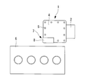
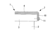
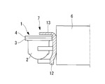
- FIG. 1 is an external perspective view of a vehicle-mounted inverter-integrated electric compressor according to a first embodiment of the present invention. It is a top view in the vehicle-mounted state of the vehicle-mounted inverter integrated electric compressor shown in FIG. It is a side view of the in-vehicle inverter integrated electric compressor according to the second embodiment of the present invention. It is a rear view in the vehicle-mounted state of the vehicle-mounted inverter integrated electric compressor which concerns on 3rd Embodiment of this invention.
- FIG. 1 shows an external perspective view of an in-vehicle inverter-integrated electric compressor according to the first embodiment of the present invention
- FIG. 2 shows a plan view in the in-vehicle state.
- the in-vehicle inverter-integrated electric compressor 1 includes a housing 2 in which an electric motor (not shown) and a compression mechanism driven by the electric motor are incorporated.
- the housing 2 may have a structure in which an aluminum die-cast motor housing and a compressor housing are integrally coupled.
- the inverter housing 3 is integrally formed on the outer periphery of the housing 2 on the side where the electric motor is built.
- the inverter accommodating portion 3 has a box shape with an upper surface opened, and an inverter device (not shown) is accommodated and installed therein.
- the inverter device converts high-voltage DC power supplied from an in-vehicle power supply unit into three-phase AC power and supplies it to the electric motor. High-voltage components such as smoothing capacitors and common mode coils, IGBTs, etc.
- a known inverter device may be used.
- the above inverter device requires insulation, moisture proofing, vibration proofing, cooling and the like, and is housed and installed in the inverter housing portion 3 in a state where the corresponding measures are taken.
- the upper surface opening of the inverter housing 3 is sealed by a lid member 4 that is fastened and fixed via a plurality of fixing screws 5 to form a waterproof structure.
- FIG. 2 is a plan view showing a state in which the in-vehicle inverter-integrated electric compressor 1 is mounted on the side wall of the engine body 6 via the bracket 12.
- the inverter-integrated electric compressor 1 is supplied with high-voltage DC power from a power supply unit mounted on the inverter device via a power cable. For this reason, when the cover member 4 of the inverter accommodating portion 3 is removed in a state where the connector of the power cable is connected during maintenance or the like, there is a risk of contact with a high voltage.
- a safety mechanism 7 for eliminating this risk in the present embodiment, as shown in FIG. 1, among the plurality of fixing screws 5 that fasten and fix the lid member 4 of the inverter accommodating portion 3. A safety cover 8 covering at least two fixing screws 5 is provided. Then, the safety cover 8 is connected to the housing 2 including the inverter accommodating portion 3 via the screw 9 on the side surface facing the side wall of the engine main body 6 which is the mounted portion of the inverter-integrated electric compressor 1 in the vehicle-mounted state. A configuration that is fixed is adopted.
- FIG. 2 shows a plan view of the inverter-integrated electric compressor 1 mounted on the side wall of the engine body 6 via a compressor mounting bracket 12 (see FIG. 4).
- the inverter-integrated electric compressor 1 is connected to a vehicle-mounted power supply unit via a power cable, and is driven by electric power supplied from the power supply unit to the inverter device installed in the inverter housing 3.
- This electric power is high-voltage direct current power, converted into three-phase alternating current power having a command frequency from a control device (not shown) by an inverter device, and supplied to an electric motor built in the housing 2.
- a safety mechanism 7 is provided so that the lid member 4 cannot be removed if the inverter-integrated electric compressor 1 remains in a vehicle.
- the safety mechanism 7 covers at least two of the plurality of fixing screws 5 that fix the lid member 4 with a safety cover 8, and uses screws 9 that fix the safety cover 8 to the housing 2 side. In the vehicle-mounted state, the lid member 4 cannot be removed in the vehicle-mounted state by being arranged on the side surface facing the side wall of the engine body 6.
- the inverter-integrated electric compressor 1 in order to remove the lid member 4 of the inverter accommodating portion 3, the inverter-integrated electric compressor 1 must be lowered from the vehicle. As a result, the connector of the power cable is inevitably disconnected to shut off the high voltage system. After that, the inverter-integrated electric compressor 1 must be lowered from the vehicle and the lid member 4 must be removed. For this reason, the cover member 4 is removed in a state where a high voltage is applied to the inverter device, and the risk of contact with the high voltage can be eliminated.
- a safety mechanism 7 that makes it impossible to remove the lid member 4 in a vehicle-mounted state, a safety cover 8 that covers at least two fixing screws 5, and a side wall of the engine body 6 that is a mounted portion when the vehicle is mounted on the safety cover 8. Therefore, the safety mechanism 7 can have a very simple configuration. Therefore, compared with the conventional safety mechanism using an interlock mechanism, a special screw, or the like, the configuration can be simplified, the installation space can be saved, and the cost can be reduced.
- FIG. 3 the structure of the safety mechanism 7 is bent as shown in FIG. 3 in which a part of the lid member 4 is bent and extended to the side surface facing the side wall of the engine body 6 that is the mounted portion when mounted on the vehicle. A portion 10 is formed, and the bent portion 10 is fixed to the inverter accommodating portion 3 or the housing 2 via two fixing screws 11 on the side facing the side wall of the engine body 6.
- the safety mechanism 7 that makes it impossible to remove the lid member 4 in the vehicle-mounted state is fixed to the bent portion 10 in which a part of the lid member 4 is bent and extended and the bent portion 10 is fixed to the housing 2 side
- a simple configuration can be achieved with only the screw 11.
- the fixing screw 11 that fixes the bent portion 10 to the housing 2 side faces the side wall of the engine body 6 that is the mounted portion and cannot be removed in the in-vehicle state, so the lid member 4 is also removed in the in-vehicle state. It becomes impossible.
- the present embodiment as well as in the first embodiment, it is possible to eliminate the danger caused by the removal of the lid member 4 in a state where a high voltage is applied, and a conventional method using an interlock mechanism, a special screw, or the like. Compared with this safety mechanism, the structure can be simplified, the installation space can be saved, and the cost can be reduced.
- FIG. 4 differs from the first embodiment described above in that the safety mechanism 7 is configured and a cover 13 that makes the fixing screw 5 of the lid member 4 unremovable is provided on the compressor mounting bracket 12. . Since other points are the same as those in the first embodiment, description thereof will be omitted.
- the safety mechanism 7 is configured such that a compressor mounting bracket 12 that mounts the inverter-integrated electric compressor 1 on the side wall of the engine body 6 has a part of its upper end.
- a cover portion 13 that extends in the horizontal direction and covers at least two fixing screws 5 of the lid member 4 in a vehicle-mounted state is integrally formed.
- the safety mechanism 7 that makes it impossible to remove the lid member 4 in a vehicle-mounted state uses an existing compressor mounting bracket 12 and at least two fixing screws 5 are used as a part thereof. It is possible to simply form the cover portion 13 that covers the cover. In addition, a part of the fixing screw 5 for fixing the lid member 4 is covered with the cover portion 13 provided on the bracket 12 in the in-vehicle state and cannot be removed. For this reason, in this embodiment as well as in the first embodiment, it is possible to eliminate the danger caused by removing the lid member 4 in a state where a high voltage is applied, and an interlock mechanism, a special screw, etc. Compared with the conventional safety mechanism used, the configuration can be simplified, the installation space can be saved, and the cost can be reduced.
- this invention is not limited to the invention concerning the said embodiment, In the range which does not deviate from the summary, it can change suitably.
- the inverter accommodating portion 3 is integrally formed with the housing 2 has been described.
- the inverter housing portion 3 is not necessarily integrally formed, and a separately formed member may be integrally assembled.
- the position where the safety cover 8, the bent portion 10, and the cover portion 13 are provided may be any position along the front-rear direction of the inverter accommodating portion 3.
- At least two fixing screws 5 are covered with the safety cover 8 and the cover portion 13 and the bent portion 10 is fixed with the two fixing screws 11.
- the number of screws of the fixing screw 5 covered by the cover portion 13 or the fixing screw 11 for fixing the bent portion 10 may be one or three or more, and it goes without saying that these are also included in the present invention. Absent.
Landscapes
- Engineering & Computer Science (AREA)
- Mechanical Engineering (AREA)
- General Engineering & Computer Science (AREA)
- Physics & Mathematics (AREA)
- Thermal Sciences (AREA)
- Compressor (AREA)
- Air-Conditioning For Vehicles (AREA)
Abstract
ハウジング(2)の外周にインバータ収容部(3)が設けられ、該インバータ収容部(3)内にインバータ装置が収容設置されるとともに、該インバータ収容部(3)の開口部がネジ止め固定される蓋部材(4)により密閉されている車載用インバータ一体型電動圧縮機(1)において、電動圧縮機(1)が車載された状態で、蓋部材(4)をインバータ収容部(3)に固定している固定ネジ(5)の一部を取り外し不能とする安全機構(7)が設けられている。
Description
本発明は、電気自動車やハイブリッド車等に搭載される空調装置用の圧縮機に適用して好適なインバータ装置が一体に組み込まれている車載用インバータ一体型電動圧縮機に関するものである。
電気自動車やハイブリッド車等に搭載される空調装置の圧縮機としては、インバータ装置が一体に組み込まれている電動圧縮機が用いられている。このインバータ一体型電動圧縮機は、圧縮機構およびそれを駆動する電動モータが内蔵されたハウジングの外周にインバータ収容部を設け、該インバータ収容部内に電源ユニットから供給される高電圧の直流電力を三相交流電力に変換して電動モータに給電するインバータ装置が収容設置された構成とされており、インバータ収容部は蓋部材により密閉されるようになっている。
車両空調装置用の電動圧縮機は、一般に車両のエンジンルーム内に搭載されるが、車載状態において、インバータ収容部を密閉している蓋部材にアクセスが可能な位置に搭載されている場合、高圧電源に繋がれている電源ケーブルのコネクタを外す等の安全処置を取らなくても蓋部材を取り外すことができる。このため、インバータ装置に高電圧を印加したままで蓋部材を取り外すことにより、うっかり高電圧に接触する危険性があった。
そこで、インバータ装置をメンテナンスする際などにおいて、作業者がインバータ収容部を密閉している蓋部材を取り外す場合、蓋部材の上面に設けられている別の保護カバーやインターロックプレートを取り外すことによって、インバータ装置に供給されている高電圧を自動的に遮断するインターロック機構を設け、蓋部材を取り外すときの安全性を確保できるようにした技術が提案されている(例えば、特許文献1,2参照)。
しかしながら、特許文献1,2に示されているインターロック機構は、インバータ収容部の蓋部材を外すことにより、高電圧が印加されたインバータ装置に接触する危険性を回避するための安全機構の構成としては、蓋部材の上面にネジ等により着脱自在に設置される保護カバーやインターロックプレートの他に、保護カバーやインターロックプレートの着脱により動作するインターロックスイッチ機構等の電流制御機器を設置することが不可欠なものである。このため、インバータ装置の構成が複雑化するとともに、インターロック機構を設置するスペースの確保やコストアップが避けられないという問題があった。
本発明は、このような事情に鑑みてなされたものであって、簡素な構成の安全機構により、高電圧が印加されたインバータ装置に接触する危険性を確実に解消することができる車載用インバータ一体型電動圧縮機を提供することを目的とする。
上記課題を解決するために、本発明の車載用インバータ一体型電動圧縮機は、以下の手段を採用する。
すなわち、ハウジングの外周にインバータ収容部が設けられ、前記インバータ収容部内にインバータ装置が収容設置されるとともに、前記インバータ収容部の開口部がネジ止め固定される蓋部材により密閉されている車載用インバータ一体型電動圧縮機において、前記電動圧縮機が車載された状態で、前記蓋部材を前記インバータ収容部に固定している固定ネジの一部を取り外し不能とする安全機構が設けられている。
すなわち、ハウジングの外周にインバータ収容部が設けられ、前記インバータ収容部内にインバータ装置が収容設置されるとともに、前記インバータ収容部の開口部がネジ止め固定される蓋部材により密閉されている車載用インバータ一体型電動圧縮機において、前記電動圧縮機が車載された状態で、前記蓋部材を前記インバータ収容部に固定している固定ネジの一部を取り外し不能とする安全機構が設けられている。
本発明によれば、インバータ収容部の開口部が蓋部材により密閉されている電動圧縮機が車載された状態で、蓋部材をインバータ収容部に固定している固定ネジの一部を取り外し不能とする安全機構が設けられているため、電動圧縮機を車載したままではインバータ収容部の蓋部材を取り外すことができず、蓋部材を取り外すには電動圧縮機を車両から下ろさなければならない。その結果、必然的に電源ケーブルのコネクタを外して高電圧系を遮断した後、電動圧縮機を車両から下ろして蓋部材を取り外さなければならなくなる。従って、インバータ装置に高電圧が印加された状態で蓋部材が外され、高電圧に接触する危険性を解消することができる。また、かかる危険性を解消するため、複雑で高価なインターロック機構や高価な特殊ネジ等を用いた安全機構を設ける必要がなく、安全機構の構成の簡素化、設置スペースの省スペース化および低コスト化を図ることができる。
さらに、上記の車載用インバータ一体型電動圧縮機において、前記安全機構は、前記固定ネジの少なくとも2個以上を取り外し不能とするように構成されていることが好ましい。
この構成によれば、安全機構が、固定ネジの少なくとも2個以上を取り外し不能とするように構成されているため、仮に2個以外の固定ネジを全て取り外したとしても、蓋部材を回転させることは困難であり、インバータ収容部の内部を開放することはできない。従って、高電圧が印加されている状態のインバータ装置に接触する危険性を確実に解消することができる。
さらに、上述のいずれかの車載用インバータ一体型電動圧縮機において、前記安全機構は、前記固定ネジの一部を覆う安全カバーと、該安全カバーを車載時に被搭載部と対向する面側において前記インバータ収容部を含む前記ハウジングに固定する固定ネジとから構成されていることが好ましい。
この構成によれば、安全機構が、固定ネジの一部を覆う安全カバーと、該安全カバーを車載時に被搭載部と対向する面側においてインバータ収容部を含むハウジングに固定する固定ネジとから構成されているので、安全機構を固定ネジの一部を覆う安全カバーと該安全カバーを固定する固定ネジのみによって簡素に構成することができ、しかも安全カバーを固定する固定ネジは、車載状態では被搭載部側に面して位置し取り外しができなくなるため、蓋部材の固定ネジも車載状態では取り外しが不能となる。従って、高電圧が印加された状態で蓋部材が取り外されることによる危険性を解消することができるとともに、インターロック機構や特殊ネジ等を用いた従来の安全機構に比べ、構成の簡素化、省スペース化および低コスト化を図ることができる。
さらに、上述のいずれかの車載用インバータ一体型電動圧縮機において、前記安全機構は、前記蓋部材の一部を車載時に被搭載部と対向する面側に折り曲げ延長した折り曲げ部と、該折り曲げ部を車載時に被搭載部と対向する面側において前記インバータ収容部を含む前記ハウジングに固定するネジとから構成されていることが好ましい。
この構成によれば、安全機構が、蓋部材の一部を車載時に被搭載部と対向する面側に折り曲げ延長した折り曲げ部と、該折り曲げ部を車載時に被搭載部と対向する面側においてインバータ収容部を含むハウジングに固定するネジとから構成されているので、安全機構を蓋部材の一部を折り曲げ延長した折り曲げ部と該折り曲げ部をハウジング側に固定するネジのみにより簡素に構成することができ、しかも折り曲げ部をハウジング側に固定するネジは、車載状態では被搭載部側に面して位置し取り外しができなくなるため、蓋部材も車載状態では取り外し不能となる。従って、高電圧が印加された状態で蓋部材が取り外されることによる危険性を解消することができるとともに、インターロック機構や特殊ネジ等を用いた従来の安全機構に比べ、構成の簡素化、省スペース化および低コスト化を図ることができる。
さらに、上述のいずれかの車載用インバータ一体型電動圧縮機において、前記安全機構は、前記電動圧縮機を車載時に被搭載部にマウントするブラケットに設けられ、車載時に前記固定ネジの一部を覆うカバー部により構成されていることが好ましい
。
。
この構成によれば、安全機構が、電動圧縮機を車載時に被搭載部にマウントするブラケットに設けられ、車載時に固定ネジの一部を覆うカバー部により構成されているので、安全機構を既存の圧縮機マウント用のブラケットに固定ネジの一部を覆うカバー部を設けることにより簡素に構成することができ、しかも蓋部材を固定する固定ネジの一部は、車載状態ではブラケットに設けられたカバー部によって覆われ、取り外しができなくなる。従って、高電圧が印加された状態で蓋部材が取り外されることによる危険性を解消することができるとともに、インターロック機構や特殊ネジ等を用いた従来の安全機構に比べ、構成の簡素化、省スペース化および低コスト化を図ることができる。
本発明によると、電動圧縮機を車載したままではインバータ収容部の蓋部材を取り外すことができず、蓋部材を取り外すには電動圧縮機を車両から下ろさなければならない。その結果、必然的に電源ケーブルのコネクタを外して高電圧系を遮断した後、電動圧縮機を車両から下ろして蓋部材を取り外さなければならなくなるため、インバータ装置に高電圧が印加された状態で蓋部材が外され、高電圧に接触する危険性を解消することができる。また、かかる危険性を解消するため、複雑で高価なインターロック機構や高価な特殊ネジ等を用いた安全機構を設ける必要がなく、安全機構の構成の簡素化、設置スペースの省スペース化および低コスト化を図ることができる。
以下に、本発明にかかる実施形態について、図面を参照して説明する。
[第1実施形態]
以下、本発明の第1実施形態について、図1および図2を用いて説明する。
図1には、本発明の第1実施形態に係る車載用インバータ一体型電動圧縮機の外観斜視図が示され、図2には、その車載状態での平面視図が示されている。
車載用インバータ一体型電動圧縮機1は、内部に図示省略の電動モータと該電動モータにより駆動される圧縮機構が内蔵されたハウジング2を備えている。なお、このハウジング2は、アルミダイカスト製のモータハウジングと圧縮機ハウジングとが一体に結合されている構成であってもよい。
[第1実施形態]
以下、本発明の第1実施形態について、図1および図2を用いて説明する。
図1には、本発明の第1実施形態に係る車載用インバータ一体型電動圧縮機の外観斜視図が示され、図2には、その車載状態での平面視図が示されている。
車載用インバータ一体型電動圧縮機1は、内部に図示省略の電動モータと該電動モータにより駆動される圧縮機構が内蔵されたハウジング2を備えている。なお、このハウジング2は、アルミダイカスト製のモータハウジングと圧縮機ハウジングとが一体に結合されている構成であってもよい。
ハウジング2の電動モータが内蔵されている側の外周には、インバータ収容部3が一体に成形されている。このインバータ収容部3は、上面が開口されたボックス形状とされており、内部に図示省略のインバータ装置が収容設置されている。インバータ装置は、車載の電源ユニットから供給される高電圧の直流電力を三相交流電力に変換して電動モータに給電するものであり、平滑コンデンサやコモンモードコイル等の高電圧系部品、IGBT等の複数個の半導体スイッチング素子から構成されるスイッチング回路が実装されたパワー系基板およびCPU等の低電圧で動作される素子から構成される制御通信回路が実装されたCPU基板等により構成されている公知のインバータ装置であってよい。
上記のインバータ装置は、絶縁、防湿、防振および冷却等が必要であり、それぞれ対応処置が施された状態でインバータ収容部3内に収容設置されている。このインバータ収容部3の上面開口部は、複数個の固定ネジ5を介して締め付け固定される蓋部材4によって密閉され、防水構造とされている。
車載用インバータ一体型電動圧縮機1は、例えばハイブリッド車に搭載される場合、エンジンルーム内において、エンジン本体(被搭載部)6の側壁等に圧縮機マウント用ブラケット12(図4参照)を介して片持ち状態で搭載されることになる。図2には、車載用インバータ一体型電動圧縮機1をエンジン本体6の側壁にブラケット12を介して搭載した状態の平面視図が示されている。インバータ一体型電動圧縮機1には、インバータ装置に対して車載されている電源ユニットから電源ケーブルを介して高電圧の直流電力が供給されることになる。このため、メンテナンス時などにおいて、電源ケーブルのコネクタを接続したままの状態でインバータ収容部3の蓋部材4を取り外すと高電圧に触れる危険性が生ずる。
この危険性を解消するための安全機構7として、本実施形態においては、図1に示されるように、インバータ収容部3の蓋部材4を締め付け固定している複数個の固定ネジ5のうちの少なくとも2個の固定ネジ5を覆う安全カバー8を設けている。そして、この安全カバー8を、車載状態においてインバータ一体型電動圧縮機1の被搭載部であるエンジン本体6の側壁と対向する側面側で、インバータ収容部3を含むハウジング2にネジ9を介して固定するようにした構成を採用している。
以上に説明の構成により、本実施形態によれば、以下の作用効果を奏する。
上記インバータ一体型電動圧縮機1をエンジン本体6の側壁に圧縮機マウント用ブラケット12(図4参照)を介して搭載した状態の平面視図が、図2に示されている。この状態でインバータ一体型電動圧縮機1は、車載の電源ユニットと電源ケーブルを介して接続され、電源ユニットからインバータ収容部3内に設置されているインバータ装置に給電される電力によって駆動される。この電力は高電圧の直流電力であり、インバータ装置によって図示省略の制御装置からの指令周波数の三相交流電力に変換され、ハウジング2内に内蔵されている電動モータに供給される。
上記インバータ一体型電動圧縮機1をエンジン本体6の側壁に圧縮機マウント用ブラケット12(図4参照)を介して搭載した状態の平面視図が、図2に示されている。この状態でインバータ一体型電動圧縮機1は、車載の電源ユニットと電源ケーブルを介して接続され、電源ユニットからインバータ収容部3内に設置されているインバータ装置に給電される電力によって駆動される。この電力は高電圧の直流電力であり、インバータ装置によって図示省略の制御装置からの指令周波数の三相交流電力に変換され、ハウジング2内に内蔵されている電動モータに供給される。
インバータ装置をメンテナンスする際には、インバータ収容部3を密閉している蓋部材4を取り外す必要があるが、電源ケーブルのコネクタを外す等の安全処置を取らないまま蓋部材4を取り外すと、うっかり高電圧に触れてしまう危険性がある。この危険性を解消するため、インバータ一体型電動圧縮機1を車載状態のままでは、蓋部材4を取り外すことができないように、安全機構7が設けられている。安全機構7は、蓋部材4を固定している複数個の固定ネジ5のうちの少なくとも2個を安全カバー8により覆い、この安全カバー8をハウジング2側に対して固定しているネジ9を、車載状態においてエンジン本体6の側壁と対向する側面側に配置することにより、車載状態では蓋部材4を外せないようにしている。
これによって、インバータ収容部3の蓋部材4を取り外すには、インバータ一体型電動圧縮機1を車両から下ろさなければならず、その結果、必然的に電源ケーブルのコネクタを外して高電圧系を遮断した後、インバータ一体型電動圧縮機1を車両から下ろして蓋部材4を取り外さなければならなくなる。このため、インバータ装置に高電圧が印加された状態で蓋部材4が外され、高電圧に接触する危険性を解消することができる。
また、上記危険性を解消するため、従来のように、複雑で高価なインターロック機構や高価な特殊ネジ等を用いた安全機構を設ける必要がなく、安全機構7の構成の簡素化、設置スペースの省スペース化および低コスト化を図ることができる。さらに、安全カバー8により複数個の固定ネジ5のうちの少なくとも2個を覆い、車載状態では取り外すことができないようにしているため、仮に2個以外の固定ネジ5を全て取り外したとしても、蓋部材4を回転させることは困難であり、インバータ収容部3の内部を開放することはできない。従って、高電圧が印加されている状態のインバータ装置に接触する危険性を確実に解消することができる。
加えて、車載状態で蓋部材4の取り外しを不能とする安全機構7を、固定ネジ5の少なくとも2個を覆う安全カバー8と該安全カバー8を車載時に被搭載部であるエンジン本体6の側壁と対向する面側においてインバータ収容部3を含むハウジング2に固定するネジ9のみから構成しているため、安全機構7を非常に簡素な構成とすることができる。従って、インターロック機構や特殊ネジ等を用いた従来の安全機構に比べ、構成の簡素化、設置スペースの省スペース化および低コスト化を図ることができる。
[第2実施形態]
次に、本発明の第2実施形態について、図3を用いて説明する。
本実施形態は、上記した第1実施形態に対して、安全カバー8を追設する代わりに蓋部材4の形状を工夫して安全機構7を構成している点が異なる。その他の点については、第1実施形態と同様であるので説明は省略する。
本実施形態においては、安全機構7の構成を、図3に示されるように、蓋部材4の一部を車載時に被搭載部であるエンジン本体6の側壁と対向する側面側に折り曲げ延長した折り曲げ部10を形成し、この折り曲げ部10をエンジン本体6の側壁と対向する面側においてインバータ収容部3またはハウジング2に2個の固定ネジ11を介して固定した構成としている。
次に、本発明の第2実施形態について、図3を用いて説明する。
本実施形態は、上記した第1実施形態に対して、安全カバー8を追設する代わりに蓋部材4の形状を工夫して安全機構7を構成している点が異なる。その他の点については、第1実施形態と同様であるので説明は省略する。
本実施形態においては、安全機構7の構成を、図3に示されるように、蓋部材4の一部を車載時に被搭載部であるエンジン本体6の側壁と対向する側面側に折り曲げ延長した折り曲げ部10を形成し、この折り曲げ部10をエンジン本体6の側壁と対向する面側においてインバータ収容部3またはハウジング2に2個の固定ネジ11を介して固定した構成としている。
上記構成とすることにより、車載状態において蓋部材4の取り外しを不能とする安全機構7を、蓋部材4の一部を折り曲げ延長した折り曲げ部10と該折り曲げ部10をハウジング2側に固定する固定ネジ11のみにより簡素に構成することができる。しかも、折り曲げ部10をハウジング2側に固定する固定ネジ11は、車載状態では被搭載部であるエンジン本体6の側壁に面して位置し取り外しができなくなるため、蓋部材4も車載状態では取り外し不能となる。従って、本実施形態でも第1実施形態と同様、高電圧が印加された状態で蓋部材4が取り外されることによる危険性を解消することができるとともに、インターロック機構や特殊ネジ等を用いた従来の安全機構に比べ、構成の簡素化、設置スペースの省スペース化および低コスト化を図ることができる。
[第3実施形態]
次に、本発明の第3実施形態について、図4を用いて説明する。
本実施形態は、上記した第1実施形態に対して、安全機構7を構成し、蓋部材4の固定ネジ5を取り外し不能にするカバー13を圧縮機マウント用ブラケット12に設けている点が異なる。その他の点については、第1実施形態と同様であるので説明は省略する。
本実施形態では、安全機構7の構成を、図4に示されるように、インバータ一体型電動圧縮機1をエンジン本体6の側壁にマウントする圧縮機マウント用ブラケット12にその上端部の一部を水平方向に延長し、車載状態において蓋部材4の固定ネジ5の少なくとも2個を覆うカバー部13を一体に形成した構成としている。
次に、本発明の第3実施形態について、図4を用いて説明する。
本実施形態は、上記した第1実施形態に対して、安全機構7を構成し、蓋部材4の固定ネジ5を取り外し不能にするカバー13を圧縮機マウント用ブラケット12に設けている点が異なる。その他の点については、第1実施形態と同様であるので説明は省略する。
本実施形態では、安全機構7の構成を、図4に示されるように、インバータ一体型電動圧縮機1をエンジン本体6の側壁にマウントする圧縮機マウント用ブラケット12にその上端部の一部を水平方向に延長し、車載状態において蓋部材4の固定ネジ5の少なくとも2個を覆うカバー部13を一体に形成した構成としている。
上記のような構成とすることにより、車載状態において蓋部材4の取り外しを不能とする安全機構7を、既存の圧縮機マウント用ブラケット12を利用し、その一部に固定ネジ5の少なくとも2個を覆うカバー部13を一体に形成して簡素に構成することができる。しかも、蓋部材4を固定する固定ネジ5の一部は、車載状態ではブラケット12に設けられたカバー部13によって覆われ、取り外しができなくなる。このため、本実施形態においても、第1実施形態と同様、高電圧が印加された状態で蓋部材4が取り外されることによる危険性を解消することができるとともに、インターロック機構や特殊ネジ等を用いた従来の安全機構に比べ、構成の簡素化、設置スペースの省スペース化および低コスト化を図ることができる。
なお、本発明は、上記実施形態にかかる発明に限定されるものではなく、その要旨を逸脱しない範囲において、適宜変形が可能である。例えば、上記実施形態では、インバータ収容部3をハウジング2に一体成形している例について説明したが、必ずしも一体成形されている必要はなく、別に成形した部材を一体に組み付けた構成としてもよい。また、安全カバー8、折り曲げ部10、カバー部13を設ける位置は、インバータ収容部3の前後方向に沿う位置のどの位置であってもよい。
さらに、上記した各実施形態では、少なくとも2個の固定ネジ5を安全カバー8、カバー部13により覆うとともに、2個の固定ネジ11により折り曲げ部10を固定する構成としているが、安全カバー8、カバー部13により覆われる固定ネジ5、あるいは折り曲げ部10を固定する固定ネジ11のネジ数は、1個または3個以上であってもよく、これらも本発明に包含されることは云うまでもない。
1 車載用インバータ一体型電動圧縮機
2 ハウジング
3 インバータ収容部
4 蓋部材
5 固定ネジ
6 エンジン本体(被搭載部)
7 安全機構
8 安全カバー
9 ネジ
10 折り曲げ部
11 固定ネジ
12 圧縮機マウント用ブラケット
13 カバー部
2 ハウジング
3 インバータ収容部
4 蓋部材
5 固定ネジ
6 エンジン本体(被搭載部)
7 安全機構
8 安全カバー
9 ネジ
10 折り曲げ部
11 固定ネジ
12 圧縮機マウント用ブラケット
13 カバー部
Claims (5)
- ハウジングの外周にインバータ収容部が設けられ、前記インバータ収容部内にインバータ装置が収容設置されるとともに、前記インバータ収容部の開口部がネジ止め固定される蓋部材により密閉されている車載用インバータ一体型電動圧縮機において、
前記電動圧縮機が車載された状態で、前記蓋部材を前記インバータ収容部に固定している固定ネジの一部を取り外し不能とする安全機構が設けられている車載用インバータ一体型電動圧縮機。 - 前記安全機構は、前記固定ネジの少なくとも2個以上を取り外し不能とするように構成されている請求項1に記載の車載用インバータ一体型電動圧縮機。
- 前記安全機構は、前記固定ネジの一部を覆う安全カバーと、該安全カバーを車載時に被搭載部と対向する面側において前記インバータ収容部を含む前記ハウジングに固定する固定ネジとから構成されている請求項1または2に記載の車載用インバータ一体型電動圧縮機。
- 前記安全機構は、前記蓋部材の一部を車載時に被搭載部と対向する面側に折り曲げ延長した折り曲げ部と、該折り曲げ部を車載時に被搭載部と対向する面側において前記インバータ収容部を含む前記ハウジングに固定するネジとから構成されている請求項1または2に記載の車載用インバータ一体型電動圧縮機。
- 前記安全機構は、前記電動圧縮機を車載時に被搭載部にマウントするブラケットに設けられ、車載時に前記固定ネジの一部を覆うカバー部により構成されている請求項1または2に記載の車載用インバータ一体型電動圧縮機。
Priority Applications (2)
| Application Number | Priority Date | Filing Date | Title |
|---|---|---|---|
| EP09834651.3A EP2372156B1 (en) | 2008-12-26 | 2009-11-13 | In-vehicle integrated-inverter electric compressor |
| US13/058,450 US8796889B2 (en) | 2008-12-26 | 2009-11-13 | In-vehicle integrated-inverter electric compressor |
Applications Claiming Priority (2)
| Application Number | Priority Date | Filing Date | Title |
|---|---|---|---|
| JP2008-335057 | 2008-12-26 | ||
| JP2008335057A JP5302669B2 (ja) | 2008-12-26 | 2008-12-26 | 車載用インバータ一体型電動圧縮機 |
Publications (1)
| Publication Number | Publication Date |
|---|---|
| WO2010073847A1 true WO2010073847A1 (ja) | 2010-07-01 |
Family
ID=42287468
Family Applications (1)
| Application Number | Title | Priority Date | Filing Date |
|---|---|---|---|
| PCT/JP2009/069325 Ceased WO2010073847A1 (ja) | 2008-12-26 | 2009-11-13 | 車載用インバータ一体型電動圧縮機 |
Country Status (4)
| Country | Link |
|---|---|
| US (1) | US8796889B2 (ja) |
| EP (1) | EP2372156B1 (ja) |
| JP (1) | JP5302669B2 (ja) |
| WO (1) | WO2010073847A1 (ja) |
Cited By (1)
| Publication number | Priority date | Publication date | Assignee | Title |
|---|---|---|---|---|
| US9812919B2 (en) | 2012-08-10 | 2017-11-07 | Mitsubishi Heavy Industries Automotive Thermal Systems Co., Ltd. | Inverter-integrated electrically driven compressor |
Families Citing this family (11)
| Publication number | Priority date | Publication date | Assignee | Title |
|---|---|---|---|---|
| CN104334414B (zh) * | 2012-04-30 | 2017-03-08 | 瑞美技术有限责任公司 | 用于覆盖进入端口的系统和方法 |
| US9809181B2 (en) | 2012-04-30 | 2017-11-07 | Borgwarner Inc. | Systems and methods for covering access ports |
| JP5699994B2 (ja) * | 2012-06-29 | 2015-04-15 | 株式会社豊田自動織機 | 電動圧縮機 |
| DE102013003513A1 (de) * | 2013-03-04 | 2014-09-04 | Wabco Gmbh | Verdichteranordnung zum Betreiben einer Druckluftversorgungsanlage, Druckluftversorgungsanlage und Druckluftversorgungssystem sowie Fahrzeug mit einer solchen Druckluftversorgungsanlage |
| US9365118B2 (en) * | 2013-06-21 | 2016-06-14 | GM Global Technology Operations LLC | High voltage protection system |
| JP6424617B2 (ja) * | 2014-12-25 | 2018-11-21 | 株式会社豊田自動織機 | 車載用電動圧縮機 |
| JP6839923B2 (ja) * | 2016-03-11 | 2021-03-10 | 三菱重工サーマルシステムズ株式会社 | 車載装置および電動圧縮機 |
| KR102103363B1 (ko) * | 2016-03-31 | 2020-04-22 | 가부시키가이샤 도요다 지도숏키 | 차량 탑재용 전동 압축기 |
| WO2017170819A1 (ja) * | 2016-03-31 | 2017-10-05 | 株式会社 豊田自動織機 | 車載用電動圧縮機 |
| JP6700610B2 (ja) | 2017-01-12 | 2020-05-27 | 株式会社豊田自動織機 | 車載用流体機械 |
| JP6942963B2 (ja) | 2017-01-12 | 2021-09-29 | 株式会社豊田自動織機 | 車載用流体機械 |
Citations (3)
| Publication number | Priority date | Publication date | Assignee | Title |
|---|---|---|---|---|
| JP2006322444A (ja) | 2005-04-18 | 2006-11-30 | Mitsubishi Heavy Ind Ltd | インバータ内蔵圧縮機 |
| JP2007113486A (ja) | 2005-10-20 | 2007-05-10 | Toyota Industries Corp | インバータ回路を有する車両補機 |
| JP2007315270A (ja) * | 2006-05-25 | 2007-12-06 | Mitsubishi Heavy Ind Ltd | インバータ一体型電動圧縮機 |
Family Cites Families (2)
| Publication number | Priority date | Publication date | Assignee | Title |
|---|---|---|---|---|
| EP1363026A3 (en) * | 2002-04-26 | 2004-09-01 | Denso Corporation | Invertor integrated motor for an automotive vehicle |
| JP4764365B2 (ja) * | 2007-02-28 | 2011-08-31 | 三菱重工業株式会社 | インバータ一体型電動圧縮機 |
-
2008
- 2008-12-26 JP JP2008335057A patent/JP5302669B2/ja active Active
-
2009
- 2009-11-13 WO PCT/JP2009/069325 patent/WO2010073847A1/ja not_active Ceased
- 2009-11-13 EP EP09834651.3A patent/EP2372156B1/en active Active
- 2009-11-13 US US13/058,450 patent/US8796889B2/en active Active
Patent Citations (3)
| Publication number | Priority date | Publication date | Assignee | Title |
|---|---|---|---|---|
| JP2006322444A (ja) | 2005-04-18 | 2006-11-30 | Mitsubishi Heavy Ind Ltd | インバータ内蔵圧縮機 |
| JP2007113486A (ja) | 2005-10-20 | 2007-05-10 | Toyota Industries Corp | インバータ回路を有する車両補機 |
| JP2007315270A (ja) * | 2006-05-25 | 2007-12-06 | Mitsubishi Heavy Ind Ltd | インバータ一体型電動圧縮機 |
Cited By (2)
| Publication number | Priority date | Publication date | Assignee | Title |
|---|---|---|---|---|
| US9812919B2 (en) | 2012-08-10 | 2017-11-07 | Mitsubishi Heavy Industries Automotive Thermal Systems Co., Ltd. | Inverter-integrated electrically driven compressor |
| DE112013003991B4 (de) | 2012-08-10 | 2019-02-28 | Mitsubishi Heavy Industries Thermal Systems, Ltd. | Elektrisch betriebener Kompressor mit integriertem Wechselrichter |
Also Published As
| Publication number | Publication date |
|---|---|
| EP2372156A4 (en) | 2017-05-17 |
| US8796889B2 (en) | 2014-08-05 |
| US20110133575A1 (en) | 2011-06-09 |
| EP2372156B1 (en) | 2018-08-15 |
| JP2010156271A (ja) | 2010-07-15 |
| EP2372156A1 (en) | 2011-10-05 |
| JP5302669B2 (ja) | 2013-10-02 |
Similar Documents
| Publication | Publication Date | Title |
|---|---|---|
| JP5302669B2 (ja) | 車載用インバータ一体型電動圧縮機 | |
| JP5951406B2 (ja) | インバータ一体型電動圧縮機 | |
| KR101616773B1 (ko) | 차량용 구동 제어 장치 | |
| JP3941423B2 (ja) | 車両用パワーコントロールユニット | |
| JP5412098B2 (ja) | インバータ一体型電動圧縮機およびそのインバータ装置 | |
| JP5107114B2 (ja) | インバータ一体型電動圧縮機 | |
| JP5107133B2 (ja) | インバータ一体型電動圧縮機 | |
| US9115707B2 (en) | Inverter module and integrated-inverter electric compressor using the same | |
| JP5393015B2 (ja) | 車載空調装置用圧縮機 | |
| US20160020657A1 (en) | Inverter-integrated electric compressor | |
| JP2009127523A (ja) | インバータ一体型電動圧縮機 | |
| CN108369863B (zh) | 电力转换装置 | |
| JP7263058B2 (ja) | 電動圧縮機 | |
| JP6021623B2 (ja) | インバータ一体型電動圧縮機 | |
| JP2009095113A (ja) | インバータ一体型電動圧縮機およびそのインバータ装置用コイル部品 | |
| JP2012117444A (ja) | インバータ収納部およびこれを備えているインバータ一体型電動圧縮機 | |
| JP2010209788A (ja) | インバータ一体型電動圧縮機 | |
| EP3197037B1 (en) | Power conversion device | |
| JP5574794B2 (ja) | インバータ一体型電動圧縮機 | |
| KR20120121514A (ko) | 인버터 | |
| JP6637382B2 (ja) | インタロック装置 |
Legal Events
| Date | Code | Title | Description |
|---|---|---|---|
| WWE | Wipo information: entry into national phase |
Ref document number: 2009834651 Country of ref document: EP |
|
| 121 | Ep: the epo has been informed by wipo that ep was designated in this application |
Ref document number: 09834651 Country of ref document: EP Kind code of ref document: A1 |
|
| WWE | Wipo information: entry into national phase |
Ref document number: 13058450 Country of ref document: US |
|
| NENP | Non-entry into the national phase |
Ref country code: DE |