WO2010074068A1 - 逆量子化方法、逆量子化装置及びプログラム - Google Patents
逆量子化方法、逆量子化装置及びプログラム Download PDFInfo
- Publication number
- WO2010074068A1 WO2010074068A1 PCT/JP2009/071303 JP2009071303W WO2010074068A1 WO 2010074068 A1 WO2010074068 A1 WO 2010074068A1 JP 2009071303 W JP2009071303 W JP 2009071303W WO 2010074068 A1 WO2010074068 A1 WO 2010074068A1
- Authority
- WO
- WIPO (PCT)
- Prior art keywords
- quantized
- video
- vector
- values
- inverse
- Prior art date
- Legal status (The legal status is an assumption and is not a legal conclusion. Google has not performed a legal analysis and makes no representation as to the accuracy of the status listed.)
- Ceased
Links
Images




Classifications
-
- H—ELECTRICITY
- H03—ELECTRONIC CIRCUITRY
- H03M—CODING; DECODING; CODE CONVERSION IN GENERAL
- H03M7/00—Conversion of a code where information is represented by a given sequence or number of digits to a code where the same, similar or subset of information is represented by a different sequence or number of digits
- H03M7/30—Compression; Expansion; Suppression of unnecessary data, e.g. redundancy reduction
- H03M7/3082—Vector coding
-
- H—ELECTRICITY
- H04—ELECTRIC COMMUNICATION TECHNIQUE
- H04N—PICTORIAL COMMUNICATION, e.g. TELEVISION
- H04N19/00—Methods or arrangements for coding, decoding, compressing or decompressing digital video signals
- H04N19/10—Methods or arrangements for coding, decoding, compressing or decompressing digital video signals using adaptive coding
- H04N19/102—Methods or arrangements for coding, decoding, compressing or decompressing digital video signals using adaptive coding characterised by the element, parameter or selection affected or controlled by the adaptive coding
- H04N19/124—Quantisation
- H04N19/126—Details of normalisation or weighting functions, e.g. normalisation matrices or variable uniform quantisers
-
- H—ELECTRICITY
- H04—ELECTRIC COMMUNICATION TECHNIQUE
- H04N—PICTORIAL COMMUNICATION, e.g. TELEVISION
- H04N19/00—Methods or arrangements for coding, decoding, compressing or decompressing digital video signals
- H04N19/10—Methods or arrangements for coding, decoding, compressing or decompressing digital video signals using adaptive coding
- H04N19/169—Methods or arrangements for coding, decoding, compressing or decompressing digital video signals using adaptive coding characterised by the coding unit, i.e. the structural portion or semantic portion of the video signal being the object or the subject of the adaptive coding
-
- H—ELECTRICITY
- H04—ELECTRIC COMMUNICATION TECHNIQUE
- H04N—PICTORIAL COMMUNICATION, e.g. TELEVISION
- H04N19/00—Methods or arrangements for coding, decoding, compressing or decompressing digital video signals
- H04N19/30—Methods or arrangements for coding, decoding, compressing or decompressing digital video signals using hierarchical techniques, e.g. scalability
- H04N19/395—Methods or arrangements for coding, decoding, compressing or decompressing digital video signals using hierarchical techniques, e.g. scalability involving distributed video coding [DVC], e.g. Wyner-Ziv video coding or Slepian-Wolf video coding
Definitions
- the present invention relates to an inverse quantization method, an inverse quantization apparatus, and a program.
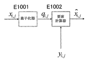
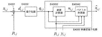
- the quantizer E1001 is described for the purpose of showing the input / output relationship with the element calculator E1002 that performs video inverse quantization, that is, the video inverse quantization technique can be configured only by the element calculator E1002. Please be careful.
- one grayscale video frame having the number of vertical pixels m and the number of horizontal pixels n is a video signal vector x.
- the related art and the present invention can also be applied to color video signals.
- the video signal vector x is a partial region of a video frame, the related art and the present invention can be applied.
- “multiple element sets” and “multiple element sets” are called “vectors”.
- the quantizer E1001 includes each element of the video signal vector x Is quantized to calculate a quantized value q i, j . If the quantizer of E1001 is a linear quantizer with a quantization width of Qs, It becomes. However, the function floor () is a floor function, and is a function that returns the maximum integer among real-valued input values.
- a set (set) of the quantized values q i, j is referred to as a quantized value vector q.
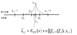
- the element calculator E1002 uses the quantized value q i, j and each element y i, j of another video signal vector y (auxiliary information y) correlated with the video signal vector x, Inverse quantization value Calculate A half-open interval corresponding to the quantized value q i, j Assuming that the conditional probability density function corresponding to the correlation is f X
- Non-Patent Documents 1, 2, and 3 proposes to use the following equation (2) ′ instead of equation (2).
- the inverse quantized video signal vector is calculated by calculating the inverse quantized value using the auxiliary information y, rather than simply inverse quantizing and calculating the inverse quantized value. The mean square error of can be reduced.
- the present invention has been invented in view of the above problems, and an object thereof is to provide a high-quality inverse quantization method, inverse quantization apparatus, and program.
- the present invention for solving the above problems is an inverse quantization method for obtaining a set of a plurality of inverse quantization values by inverse quantization using a plurality of quantization values as a set, and for each quantization value, the inverse quantization value is obtained.
- a range of obtained values is obtained using at least a signal other than the quantized value, and a set of provisional inverse quantized values that minimize the total variation norm within the range of possible values for each inverse quantized value It is characterized in that it is obtained as a set of quantized values.
- the present invention for solving the above problems is an inverse quantization method for obtaining a set of a plurality of inverse quantized values by inversely quantizing a plurality of quantized values as a set, wherein the plurality of quantized values and the quantized values are obtained.
- a temporary inverse quantized value of each quantized value of each of the plurality of quantized values is calculated element by element, and the quantized value is dequantized for each quantized value using the plurality of quantized values.
- the range of possible values is obtained, and the total variation norm is minimized within the range of possible values for each inverse quantized value, starting from the set of provisional inverse quantized values calculated in element units.
- a set of provisional inverse quantized values is obtained as the set of inverse quantized values.
- the present invention that solves the above-described problem is an encoding method for encoding a plurality of quantized values, and performs inverse quantization by using a plurality of quantized values as a set to obtain a set of a plurality of dequantized values.
- the inverse quantization method uses a method other than at least a signal other than the quantized value to determine a range of values that can be taken for each quantized value. Within the range, a set of provisional inverse quantization values having a minimum total variation norm is obtained as the set of inverse quantization values.
- the present invention that solves the above-described problem is an encoding method for encoding a plurality of quantized values, and performs inverse quantization by using a plurality of quantized values as a set to obtain a set of a plurality of dequantized values.
- the inverse quantization method uses the plurality of quantized values and a signal other than the quantized value to calculate a provisional inverse quantized value of each quantized value of the plurality of quantized values.
- the range of values that can be taken by the inverse quantization value for each quantization value using the plurality of quantization values is obtained, and the set of provisional inverse quantization values calculated in units of the elements is used as a starting point.
- a set of provisional inverse quantization values that minimize the total variation norm within a range of possible values for each inverse quantization value is obtained as the set of inverse quantization values.
- the present invention for solving the above-described problem is a decoding method for decoding a plurality of quantized values, and an inverse quantization method for obtaining a set of a plurality of dequantized values by dequantizing a plurality of quantized values as a set.
- the dequantization method uses a range of values that can be taken by the dequantized value for each quantized value using at least a signal other than the quantized value, and is within the range of values that can be taken for each dequantized value. Then, a set of provisional inverse quantized values that minimize the total variation norm is obtained as the set of inverse quantized values.
- the present invention for solving the above-described problem is a decoding method for decoding a plurality of quantized values, and an inverse quantization method for obtaining a set of a plurality of dequantized values by dequantizing a plurality of quantized values as a set.
- the inverse quantization method uses the plurality of quantization values and a signal other than the quantization value to calculate a provisional inverse quantization value of each quantization value of the plurality of quantization values in element units.
- the present invention for solving the above-mentioned problem is a video inverse quantization method for calculating an inverse quantized video vector from a quantized value vector corresponding to a current video vector to be processed.
- a video element calculation step of calculating an initial dequantized video vector element by element using other video vector elements having a correlation between them and the quantized value vector elements; and
- a set of provisional inversely quantized video vectors determined from the calculated initial dequantized video vector as a starting point and another quantized vector and a correlation between the video vector to be processed and the quantized value vector
- a video vector calculating step for calculating a provisional inverse quantized video vector having a minimum total variation norm as the inverse quantized video vector. And butterflies.
- the present invention for solving the above-mentioned problem is a video inverse quantization method for calculating an inverse quantized video vector from a quantized value vector corresponding to a current video vector to be processed.
- a video element calculation step of calculating an initial dequantized video vector element by element using other video vector elements having a correlation between them and the quantized value vector elements; and From a set of provisional inverse quantized video vectors determined by the quantized value vector, starting from the calculated initial inverse quantized video vector, a provisional inverse quantized video vector having a minimum total variation norm is obtained from the inverse quantum.
- a video vector calculation step for calculating as a normalized video vector.
- the present invention for solving the above-mentioned problems is a video inverse quantization method for calculating an inverse quantized video vector from a quantized value vector corresponding to a current video vector to be processed, wherein an element of the quantized value vector is calculated.
- a video element calculation step for calculating an initial dequantized video vector element by element, and an initial dequantized video vector calculated in the video element calculation step as a starting point between the video vector to be processed From the set of provisional inverse quantized video vectors determined by the other quantized vector and the quantized value vector, the provisional inverse quantized video vector having the minimum total variation norm is determined as the inverse quantized video vector.
- the present invention for solving the above-mentioned problem is a video encoding method for encoding a quantized value vector, wherein the inverse quantized video vector is calculated from the quantized value vector corresponding to the current video vector to be processed.
- the image inverse quantization method uses the elements of other image vectors that have a correlation with the image vector to be processed and the elements of the quantized value vectors.
- the present invention for solving the above-described problem is a video decoding method for decoding a quantized value vector, wherein the inverse quantized video vector is calculated from the quantized value vector corresponding to the current video vector to be processed.
- the video dequantization method uses an element of another video vector that has a correlation with the video vector to be processed, and an element of the quantized value vector.
- a video element calculation step for calculating an initial dequantized video vector element by element, and a correlation between the initial dequantized video vector calculated in the video element calculation step and the target video vector From the vector space determined by the other video vector and the quantized value vector, the provisional inverse quantized video vector having the minimum total variation norm is converted to the inverse quantum And having a video vector calculation step of calculating as a video vector.
- the present invention that solves the above-described problem is an inverse quantization device that obtains a set of a plurality of inverse quantization values by inversely quantizing a plurality of quantization values as a set, and takes the inverse quantization value for each quantization value.
- a range of obtained values is obtained using at least a signal other than the quantized value, and a set of provisional inverse quantized values that minimize the total variation norm within the range of possible values for each inverse quantized value It is characterized by having a restoring means for obtaining a set of quantized values.
- the present invention for solving the above problem is an inverse quantization apparatus that obtains a set of a plurality of inverse quantized values by inversely quantizing a plurality of quantized values as a set, wherein the plurality of quantized values and the quantized values are obtained.
- a temporary inverse quantized value of each quantized value of each of the plurality of quantized values is calculated element by element, and the quantized value is dequantized for each quantized value using the plurality of quantized values.
- the range of possible values is obtained, and the total variation norm is minimized within the range of possible values for each inverse quantized value, starting from the set of provisional inverse quantized values calculated in element units.
- the present invention is characterized by comprising restoration means for obtaining a set of provisional inverse quantization values as the set of inverse quantization values.
- the present invention that solves the above-described problem is an encoding device that encodes a plurality of quantized values, and performs inverse quantization on a plurality of quantized values as a set to obtain a set of a plurality of dequantized values.
- the inverse quantization device obtains a range of possible values of the inverse quantized value for each quantized value using at least a signal other than the quantized value, and a possible value for each inverse quantized value. In this range, there is provided means for obtaining a set of provisional inverse quantization values having a minimum total variation norm as the set of inverse quantization values.
- the present invention that solves the above-described problem is an encoding device that encodes a plurality of quantized values, and performs inverse quantization on a plurality of quantized values as a set to obtain a set of a plurality of dequantized values.
- the inverse quantization device uses the plurality of quantized values and signals other than the quantized values as elements to calculate provisional inverse quantized values of the quantized values of the quantized values.
- the present invention that solves the above-described problem is a decoding device that decodes a plurality of quantized values, and an inverse quantizing device that obtains a set of a plurality of dequantized values by dequantizing a plurality of quantized values as a set.
- the inverse quantization device obtains a range of possible values of the inverse quantized value for each quantized value by using at least a signal other than the quantized value, and a range of possible values of the inverse quantized value
- the present invention that solves the above-described problem is a decoding device that decodes a plurality of quantized values, and an inverse quantizing device that obtains a set of a plurality of dequantized values by dequantizing a plurality of quantized values as a set. And the dequantization device uses the plurality of quantized values and a signal other than the quantized value to calculate a provisional inverse quantized value of each quantized value of the plurality of quantized values in element units.
- the present invention for solving the above-mentioned problems is a video inverse quantization apparatus for calculating an inverse quantized video vector from a quantized value vector corresponding to a current video vector to be processed, Video element calculation means for calculating an initial dequantized video vector element by element using other video vector elements having a correlation between them and the quantized value vector elements; and the video element calculation means A set of provisional inversely quantized video vectors determined from the calculated initial dequantized video vector as a starting point and another quantized vector and a correlation between the video vector to be processed and the quantized value vector And a video vector calculating means for calculating a provisional inverse quantized video vector having a minimum total variation norm as the inverse quantized video vector.
- the present invention for solving the above-mentioned problems is a video inverse quantization apparatus for calculating an inverse quantized video vector from a quantized value vector corresponding to a current video vector to be processed, Video element calculation means for calculating an initial dequantized video vector element by element using other video vector elements having a correlation between them and the quantized value vector elements; and the video element calculation means From a set of provisional inverse quantized video vectors determined by the quantized value vector, starting from the calculated initial inverse quantized video vector, a provisional inverse quantized video vector having a minimum total variation norm is obtained from the inverse quantum. And a video vector calculating means for calculating as a normalized video vector.
- the present invention for solving the above-mentioned problems is a video inverse quantization device for calculating an inverse quantized video vector from a quantized value vector corresponding to a current video vector to be processed, wherein an element of the quantized value vector is calculated.
- the video element calculation means for calculating the initial dequantized video vector element by element, and the video vector to be processed starting from the initial dequantized video vector calculated by the video element calculation means From the set of provisional inverse quantized video vectors determined by the other quantized vector and the quantized value vector, the provisional inverse quantized video vector having the minimum total variation norm is determined as the inverse quantized video vector.
- the present invention that solves the above-described problem is a video encoding device that encodes a quantized value vector, and calculates a dequantized video vector from a quantized value vector corresponding to the current video vector to be processed.
- An inverse quantization device wherein the image inverse quantization device uses the element of another video vector having a correlation with the video vector to be processed and the element of the quantized value vector.
- Video element calculation means for calculating an initial dequantized video vector to be processed in element units, and an initial dequantized video vector calculated by the video element calculation means as a starting point, and the video vector to be processed From the vector space determined by another video vector having a correlation between the quantized value vector and the quantized value vector, a provisional inverse quantized video vector having a minimum total variation norm is converted to the inverse quantized video vector. And having a video vector calculating means for calculating as a vector.
- the present invention that solves the above-described problem is a video decoding apparatus that decodes a quantization value vector, and calculates a dequantized video vector from a quantization value vector corresponding to a current video vector to be processed. And the video inverse quantization device uses the elements of other video vectors that have a correlation with the video vector to be processed and the elements of the quantized value vectors.
- a provisional inverse quantized video vector having a minimum total variation norm is obtained from the inverse quantized video vector.
- having a video vector calculation means for calculating a torque is obtained from the image element calculation means for calculating the initial dequantized video vector of each element.
- the present invention for solving the above problems is an inverse quantization program for obtaining a set of a plurality of inverse quantized values by inversely quantizing a plurality of quantized values, and for each quantized value, the inverse quantized value is obtained.
- a process of obtaining a range of values to be obtained using at least a signal other than the quantized value, and a set of provisional inverse quantized values that minimize the total variation norm within a range of possible values for each inverse quantized value The information processing apparatus is caused to execute processing for obtaining the set of inverse quantized values.
- the present invention that solves the above-described problem is an inverse quantization program for inversely quantizing a plurality of quantized values as a set to obtain a set of a plurality of inverse quantized values, wherein the plurality of quantized values and the quantized values are obtained.
- a range of possible values of the quantized value is obtained, and a set of provisional inverse quantized values calculated for each element is used as a starting point.
- the information processing apparatus is caused to execute a process of obtaining a minimum provisional dequantized value set as the dequantized value set.
- the present invention that solves the above problem is an encoding program for encoding a plurality of quantized values, and performs inverse quantization on a plurality of quantized values as a set to obtain a set of a plurality of dequantized values.
- the inverse quantization process includes a process for obtaining a range of possible values of the inverse quantization value for each quantization value using at least a signal other than the quantization value, and for each inverse quantization value.
- the information processing apparatus is caused to execute a process of obtaining a set of provisional inverse quantization values having a minimum total variation norm as the set of inverse quantization values.
- the present invention that solves the above problem is an encoding program for encoding a plurality of quantized values, and performs inverse quantization on a plurality of quantized values as a set to obtain a set of a plurality of dequantized values.
- the inverse quantization process uses the plurality of quantized values and a signal other than the quantized value to calculate a provisional inverse quantized value of each quantized value of the plurality of quantized values.
- a process of calculating in element units, and obtaining a range of values that can be obtained by dequantization values for each quantized value using the plurality of quantized values, and a set of provisional dequantized values calculated in element units Processing to obtain a set of provisional inverse quantized values that minimize the total variation norm within the range of possible values for each inverse quantized value as a starting point as the set of inverse quantized values to the information processing apparatus It is made to perform.
- the present invention that solves the above problem is a program of a decoding method for decoding a plurality of quantized values, and performs inverse quantization by dequantizing a plurality of quantized values as a set to obtain a set of a plurality of dequantized values
- the inverse quantization process includes: a process for obtaining a range of values that can be taken by the dequantized value for each quantized value using at least a signal other than the quantized value;
- the information processing apparatus is configured to execute processing for obtaining a set of provisional inverse quantization values having a minimum total variation norm as the set of inverse quantization values within a range of obtained values.
- the present invention for solving the above problems is a decoding program for decoding a plurality of quantized values, and performs inverse quantization on a plurality of quantized values as a set to obtain a set of a plurality of dequantized values.
- the inverse quantization process uses the plurality of quantized values and a signal other than the quantized value as a unit of a provisional inverse quantized value of each quantized value of the plurality of quantized values.
- the range of possible values of the inverse quantized values is obtained for each quantized value, and the set of provisional inverse quantized values calculated for each element is used as the starting point.
- the information processing apparatus to execute processing for obtaining a set of provisional inverse quantized values that minimize the total variation norm as the set of inverse quantized values within a range of possible values for each inverse quantized value. It is characterized by that.
- the present invention for solving the above-described problem is a video inverse quantization program for calculating a dequantized video vector from a quantized value vector corresponding to a current video vector to be processed, the video vector to be processed, A video element calculation process for calculating an initial dequantized video vector element by element using another quantized vector element and a quantized value vector element; and the video element calculating process.
- a video vector calculation process for calculating a provisional inverse quantized video vector having a minimum total variation norm from the set as the inverse quantized video vector is implemented in the information processing apparatus. Characterized in that to.
- the present invention for solving the above-described problem is a video inverse quantization program for calculating a dequantized video vector from a quantized value vector corresponding to a current video vector to be processed, the video vector to be processed, A video element calculation process for calculating an initial dequantized video vector element by element using another quantized vector element and a quantized value vector element; and the video element calculating process. From the set of provisional inverse-quantized video vectors determined by the quantized value vector, starting from the initial inverse-quantized video vector calculated in the above step, the provisional inverse-quantized video vector having the minimum total variation norm is converted into the inverse A video vector calculation process for calculating a quantized video vector is executed by an information processing apparatus.
- the present invention for solving the above problems is a video inverse quantization program for calculating an inverse quantized video vector from a quantized value vector corresponding to a current video vector to be processed, the element of the quantized value vector
- a video element calculation process for calculating an initial dequantized video vector element by element, and an initial dequantized video vector calculated in the video element calculation process as a starting point, From the set of provisional inversely quantized video vectors determined by the other quantized vector and another video vector having a correlation between them, the inversely quantized video vector having a minimum total variation norm is obtained from the inversely quantized video vector.
- a video vector calculation process for calculating as a vector is executed by an information processing apparatus.
- the present invention for solving the above-described problems is a video encoding program for encoding a quantized value vector, and calculates the inverse quantized video vector from the quantized value vector corresponding to the current video vector to be processed.
- a video inverse quantization process wherein the video inverse quantization process uses an element of another video vector having a correlation with the video vector to be processed and an element of the quantized value vector
- a video element calculation process for calculating the initial dequantized video vector to be processed in element units, and an initial dequantized video vector calculated by the video element calculation process as a starting point, From the vector space determined by the other quantized vector and the quantized value vector, the inverse inverse quantized video vector having the minimum total variation norm is converted to the inverse Wherein the coca to perform the video vector calculation processing for calculating the image vector to the information processing apparatus.
- the present invention for solving the above-described problem is a video decoding program for decoding a quantized value vector, and a video inverse program for calculating an inverse quantized video vector from a quantized value vector corresponding to a current video vector to be processed.
- a quantization process wherein the video inverse quantization process uses the elements of other video vectors that have a correlation with the video vector to be processed and the elements of the quantized value vectors.
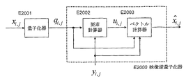
- FIG. 1 is an explanatory diagram of related technology.
- FIG. 2 is a conceptual diagram of element inverse quantization.
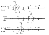
- FIG. 3 is a conceptual diagram of the result of initial dequantized video signal vector calculation.
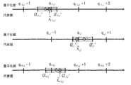
- FIG. 4 is a conceptual diagram of the range.
- FIG. 5 is a conceptual diagram of the final inverse quantized video signal vector calculation result.
- FIG. 6 is a block diagram of the first embodiment.
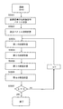
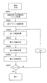
- FIG. 7 is a flowchart of the first embodiment.
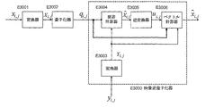
- FIG. 8 is a configuration diagram of the second embodiment.
- FIG. 9 is a flowchart of the second embodiment.
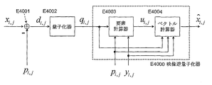
- FIG. 10 is a configuration diagram of the third embodiment.
- FIG. 11 is a flowchart of the third embodiment.
- FIG. 12 is a configuration diagram of the fourth embodiment.
- FIG. 13 is a flowchart of the fourth embodiment.
- FIG. 1 is an explanatory diagram of related technology.
- FIG. 2 is a conceptual diagram of element inverse quantization.
- FIG. 3 is a
- FIG. 14 is another configuration diagram in the first embodiment.
- FIG. 15 is another configuration diagram in the second embodiment.
- FIG. 16 is another configuration diagram in the third embodiment.
- FIG. 17 is another configuration diagram in the fourth embodiment.
- FIG. 18 is another configuration diagram in the first embodiment.
- FIG. 19 is another configuration diagram in the second embodiment.
- FIG. 20 is another configuration diagram according to the third embodiment.
- FIG. 21 is another configuration diagram according to the fourth embodiment.
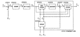
- FIG. 22 is a block diagram of a video encoder using a video inverse quantizer.
- FIG. 23 is a block diagram of a video decoder using a video inverse quantizer.
- FIG. 24 is a configuration diagram of the information processing apparatus according to this embodiment.
- FIG. 25 is a diagram for explaining a specific example of the effect in the present embodiment.
- a video signal is composed of a flat area where the signal value changes slowly, an edge area where the signal value changes sharply, and a texture area where the signal value vibrates violently. It is sensitive to noise in the area and insensitive to noise in the texture area.
- the present invention relates to an inverse quantized video signal vector (hereinafter referred to as an initial inverse quantized video signal vector) calculated element by element according to the related art described above, so that the oscillation of the video signal vector becomes smaller.
- an inverse quantized video signal vector hereinafter referred to as an initial inverse quantized video signal vector
- the non-variation norm is minimized.
- the total variation minimization method of Patent Document 4 or the bilateral filter of Non-Patent Document 5 is used.
- a set of vectors in which an inverse quantized video signal vector (original video signal vector) exists is accurately limited by using the quantized value, the auxiliary information, and the conditional probability density function.
- a vector space corresponding to the set of vectors is simply referred to as a partial vector space
- the final dequantized video signal vector is calculated in the partial vector space.
- the point of accurately limiting the partial vector space is different from Non-Patent Document 6 that suppresses noise caused by JPEG compression using the total variation minimization method.
- Non-Patent Document 6 uses the auxiliary information to dequantize the video signal vector.
- the related art method of reducing the mean square error cannot be considered.
- the initial dequantized video signal vector is calculated in the same manner as in the related art (FIG. 3).
- the present invention uses the quantized values q i, j , the auxiliary information elements y i, j , and the conditional probability density function f X
- the partial vector space U in which the original video signal vector exists is a partial vector space defined by the quantized values q i, j. Note that it is a limited subvector space (ie, U is a sub-space of V).
- the present invention calculates a final dequantized video signal vector from the initial dequantized video signal vector in the partial vector space U, and outputs the result as a dequantized video vector.
- FIG. 5 shows the sum of absolute value errors between vertically adjacent elements. This is an example of calculating the final inverse quantized video signal vector such that becomes smaller.
- the final dequantized video vector is a video vector in which the vibration of the signal value in a flat region (edge sensitive to human vision) or an edge region is suppressed without blurring. Therefore, it is possible to avoid the local deterioration from being noticeable.
- the dequantized video signal vector should be calculated so that continuity in the time direction is improved. It is. Therefore, in another means of the present invention, each element y i, j of the auxiliary information and the element of the initial dequantized video signal vector If the absolute difference value of the sub information is smaller than a certain threshold, or if the element y i, j of the auxiliary information is included in the range of the corresponding element of the partial vector space, the corresponding value of the final dequantized video signal vector The calculation of the final dequantized video signal vector is constrained so that the element x i, j takes a value close to the element y i, j of the auxiliary information. According to the present invention, continuity in the time direction is improved, and flickering of images can be suppressed.
- the above-described means of the present invention can be used as a decoding means for local decoding of the video signal in the video encoding method for encoding the quantized value.
- the present invention can provide a higher quality video encoding method.
- the above-described means of the present invention can be used as a decoding means for the video signal in the video decoding method for decoding the quantized value.
- the present invention can provide a higher quality video decoding method.
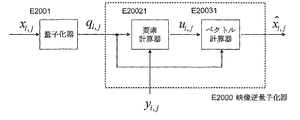
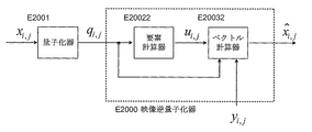
- the quantizer E2001 (same as that of the related art of FIG. 1) Is quantized to calculate a quantized value q i, j . If the quantizer of E2001 is a linear quantizer with a quantization width of Qs, It becomes.
- the set of the quantized values q i, j is referred to as a quantized value vector q.
- the video inverse quantizer E2000 includes an element calculator E2002 and a vector calculator E2003.
- the element calculator E2002 and the vector calculator E2003 receive the quantized value vector q and another video signal vector y (hereinafter referred to as auxiliary information y) correlated with the video signal vector x, and perform inverse processing. Quantized video signal vector Calculate Each is described below.
- the element calculator E2002 calculates each element value u i, j of the initial dequantized video signal vector u using the quantized value vector q and the auxiliary information y input thereto.
- the element calculator E2002 calculates a conditional probability density function corresponding to the correlation as f X
- the auxiliary information y is a video signal vector of a frame adjacent to the video signal vector x to be dequantized in the time direction
- the inverse quantized video signal vector is calculated so that the continuity in the time direction is improved. Should do.
- the element calculator E2002 determines that the absolute difference value between each element y i, j of the auxiliary information and the element u i, j obtained by the equation (4) is smaller than a predetermined threshold value, or , A half-open interval corresponding to the quantized value q i, j corresponding to the element y i, j of the auxiliary information
- u i, j calculated by the formula (4) or the formula (4) ′ may be updated by the following formula (5) or the formula (5) ′.
- the auxiliary information y includes the video signal vector of each element of the video signal vector of the frame adjacent in the time direction by motion compensation prediction. It is even better if the video signal vector is aligned with each element of x. (That is, the auxiliary information y may be a video signal vector in which each element of the video signal vector of frames adjacent in the time direction is aligned with each element of the video signal vector x by motion compensation prediction.)
- the vector calculator E2003 updates the input dequantized video signal vector u with less vibration based on the input auxiliary information y and the quantized value vector q, Update result with final dequantized video signal vector Output as.
- the vector calculator E2003 determines the range of each element x i, j from the quantized value q i, j , the auxiliary information element y i, j , and the conditional probability density function f X
- min_x is the minimum value of x at which the conditional probability density function f X
- max_x is the maximum of x at which the conditional probability density function f X
- min_x and max_x may be calculated from the standard deviation of the conditional probability density function fX
- the vector calculator E2003 is a predetermined number of times k, initialization dequantized video signal vector u (hereinafter, u 0 and write) as starting point, the first projection and the second projection described below Iteratively repeats to calculate a dequantized video signal vector with less vibration from the partial vector space U.
- k corresponds to the sequential number of repetitions of a certain point in time
- the inverse quantization at the time u k is said sequential repetition has been applied k times the superscript u k described below (superscript)
- U 0 is an initial dequantized video signal vector.
- Said first projection is an inverse quantization video signal vector u k to be inputted, a process of updating more dequantized video signal vector u k + 1 small vibration.
- an objective function J (s) that is a total variation norm defined by the following equation (8) and a constraint function G (s, u k , ⁇ ) defined by the following equation (11):
- the video signal vector s that minimizes the functional F (s, u k , ⁇ ) of the formula (12) that is the sum of the above and s is calculated, and the solution s is set to u k + 1 .
- the result of the first projection (u k + 1 ) can be obtained by solving the following equation (13).
- the objective function J (s) is minimized under the constraint function G (s, u k , ⁇ ), and s having a small total variation norm is obtained.
- a sub-gradient method such as Non-Patent Document 6 or a projection method such as Non-Patent Document 7 may be used.
- the above-described ⁇ may be a positive real number depending on the quantization width Qs.
- the second projection is a process of limiting the input inverse quantized video signal vector uk + 1 to the partial vector space U. Specifically, the following equation (14) is applied to all elements u i, j of the inversely quantized video signal vector u k + 1 . Finally, the vector calculator E2003, only K times, a first projection and said final dequantized video signal vector u k obtained by alternately repeating the second projection as described above Output as.
- step S2001 the initial dequantized video signal vector u is calculated by the element calculator E2002 described above. Then, it progresses to step S2002.
- step S2002 the vector calculator E2003 described above calculates the partial vector space U. Then, it progresses to step S2003.
- step S2003 the vector calculator E2003 described above, the first projection as described above the current inverse quantized video signal vector u k, is updated more dequantized video signal vector u k + 1 small vibration. Then, it progresses to step S2004.
- step S2004 the vector calculator E2003 described above restricts the current inverse-quantized video signal vector uk + 1 to the partial vector space U by the second projection described above. Then, it progresses to step S2005.
- step S2005 it is determined whether the counter k is equal to a predetermined value K. If they are equal, the process is terminated. Otherwise, the counter k is incremented by 1, and the process returns to step S2003. When returning to step S2003, it is desirable to change the variable ⁇ of the first projection described above to a smaller positive value.
- the configuration of the video inverse quantization technique of the invention in this embodiment will be described.
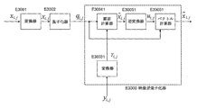
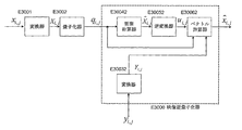
- the converter E3001 and the quantizer E3002 in FIG. 8 are described for the purpose of showing the input / output relationship with the video inverse quantizer E3000 for inversely quantizing the video, that is, the video inverse quantization of the invention.
- the technology can only consist of video inverse quantizer E3000.
- the converter E3001 converts the frequency of the video signal vector x to a conversion coefficient value Calculate As the frequency conversion, DCT (Discrete Cosine Transform) in units of 8 ⁇ 8 blocks can be used.
- DCT Discrete Cosine Transform
- the set of transform coefficient values X i, j is referred to as a transform coefficient value vector X.
- the quantizer E3002 (which is the same operation as that of the related art of FIG. 1) quantizes each transform coefficient value X i, j obtained by the transformer E3001, and calculates a quantized value q i, j . . If the quantizer of E3002 is a linear quantizer with a quantization width of Qs, It becomes.
- the function sign () is a function that returns a sign ( ⁇ ) of a real value input value
- the function floor () is a function that returns the maximum integer among the real value input values.
- the set of the quantized values q i, j is referred to as a quantized value vector q.
- the video inverse quantizer E3000 includes a converter E3003, an element calculator E3004, an inverse converter E3005, and a vector calculator E3006.
- the input of the video inverse quantizer E3000 is another video signal vector y having a correlation between the quantized value vector q and the video signal vector x in the frequency domain.
- the converter E3003 frequency-converts the other video signal vector y inputted, and calculates a conversion coefficient value vector Y (hereinafter, auxiliary information Y).
- the element calculator E3004 receives the auxiliary information Y and the quantized value vector q as inputs, and performs an inverse quantized transform coefficient value vector. Calculate Specifically, a half-open interval corresponding to the quantized values q i, j is defined as If the conditional probability density function corresponding to the above-mentioned correlation is f X
- the element calculator E3004 uses each element Y i, j of the auxiliary information and the element obtained by the equation (4). Or a half-open interval corresponding to the quantized value q i, j corresponding to the element Y i, j of the auxiliary information Calculated by Equation (16) or Equation (16) ' May be updated with the following Expression (17) or Expression (17) ′.
- the video signal vector y is a video signal vector in which each element of the video signal vector of the frame adjacent in the time direction is aligned with each element of the video signal vector x by motion compensation prediction.
- the other video signal vector y may be a video signal vector in which each element of a video signal vector of a frame adjacent in the time direction is aligned with each element of the video signal vector x by motion compensation prediction.
- the inverse transformer E3005 is an inverse quantization transform coefficient value vector obtained by the element calculator E3004. Is subjected to inverse frequency transformation to calculate an initial dequantized video signal vector u.
- the vector calculator E3006 uses the quantized value vector q and the auxiliary information Y to convert the initial dequantized video signal vector u obtained by the inverse transformer E3005 into a dequantized video signal with less vibration. Update vector, final dequantized video signal vector Output as.
- the vector calculator E3006 calculates each element X of the video signal vector in the frequency domain from the quantized value q i, j , the auxiliary information element Y i, j , and the conditional probability density function f X
- min_x the probability density function f X the conditional
- max_x the probability density function f X the conditional
- min_x and max_x may be calculated from the standard deviation of the conditional probability density function fX
- the range of transform coefficient values X i, j obtained by Equation (18) and Equation (19) Subvector space defined by And
- the partial vector space U is a value range in the frequency domain of the original video signal vector x.
- the vector calculator E3006 is a predetermined number of times K, the initial inverse quantization video signal vector u (hereinafter, u 0 and write) as starting point, sequentially repeating the projection from the first to describe the fourth below From the partial vector space U, an inverse quantized video signal vector with less vibration is calculated.
- k corresponds to the sequential number of repetitions of a certain point in time
- the inverse quantization at the time u k is said sequential repetition has been applied k times the superscript u k described below (superscript)
- U 0 is an initial dequantized video signal vector.
- Said first projection is an inverse quantization video signal vector u k to be inputted, a process of updating more dequantized video signal vector u k + 1 small vibration.
- an objective function J (s) that is a total variation norm defined by the following equation (20) and a constraint function G (s, u k , ⁇ ) defined by the following equation (23):
- the video signal vector s that minimizes the functional F (s, u k , ⁇ ) of the equation (24) that is the sum of and s is calculated, and the solution s is set to u k + 1 .
- the result of the first projection (u k + 1 ) is obtained by calculating the following equation (25).
- the objective function J (s) is minimized under the constraint function G (s, u k , ⁇ ), and s having a small total variation norm is obtained. That is, s with less vibration can be obtained.
- a sub-gradient method such as Non-Patent Document 6 or a projection method such as Non-Patent Document 7 may be used.
- the above-described ⁇ may be a positive real number depending on the quantization width Qs.
- the second projection projects the inverse quantized video signal vector uk + 1 to the frequency domain. Specifically, as in the case of the converter E3003, u k + 1 is frequency-converted into the frequency domain, and the inverse quantization transform coefficient value vector U k + 1 is calculated.
- the third projection is a process of limiting the input inverse quantization transform coefficient value vector U k + 1 to the partial vector space U. Specifically, the following formula is applied to all elements U ij .
- the inverse quantization transform coefficient value vector U k + 1 is projected onto the spatial domain. Specifically, in the same manner as the inverse transformer E3005, U k + 1 is subjected to inverse frequency conversion to calculate an inverse quantized video signal vector u k + 1 .
- the vector calculator E3006 only K times, wherein the u k obtained by sequentially repeating the fourth projection from the first described above final dequantized video signal vector Output as.
- step S3001 the initial dequantized video signal vector u is calculated by the element calculator E3004 and the inverse transformer E3005 described above. Subsequently, the operation proceeds to step S3002.
- step S3002 the partial vector space U is calculated by the vector calculator E3006 described above. Subsequently, the operation proceeds to step S3003.
- step S3003 the vector calculator E3006 described above, the first projection as described above the current inverse quantized video signal vector u k, is updated more dequantized video signal vector u k + 1 small vibration. Subsequently, the process proceeds to step S3004.
- step S3004 the vector calculator E3006 described above converts the inverse quantized video signal vector uk + 1 obtained in step S3003 into the frequency domain by the second projection described above. Subsequently, the operation proceeds to step S3005.
- step S3005 the vector calculator E3006 described above restricts the inverse quantization transform coefficient value vector U k + 1 obtained in step S3004 to the partial vector space U by the third projection described above. Subsequently, the process proceeds to step S3006.
- step S3006 the vector calculator E3006 described above projects the inverse quantization transform coefficient value vector U k + 1 obtained in step S3005 onto the spatial domain by the fourth projection described above. Subsequently, the operation proceeds to step S3007.
- step S3007 it is determined whether the counter k is equal to a predetermined value K. If they are equal, the process is terminated. Otherwise, the counter k is incremented by 1, and the process returns to step S3003. When returning to step S3003, it is desirable to change the variable ⁇ of the first projection described above to a smaller positive value.
- the video inverse quantizer of the present invention when the quantized value that is the input of the video inverse quantizer is the quantized value of the prediction error value predicted from the video signal vector will be described.
- the configuration of the video inverse quantization technique of the invention in this embodiment will be described.
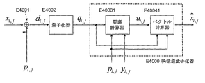
- the subtractor E4001 and the quantizer E4002 in FIG. 10 are described for the purpose of showing the input / output relationship with the video inverse quantizer E4000 that inversely quantizes the video, that is, the video inverse quantization of the invention.
- the technology can only consist of video inverse quantizer E4000.
- the subtractor E4001 subtracts each element p i, j of the prediction signal vector p from each element x i, j of the video signal vector x to obtain a prediction error value.
- the set of the prediction error values d i, j is referred to as a prediction error value vector d.
- the processed element adjacent to the current processing target element is used as the predicted signal vector p. Predictive signals generated from can be used.
- a quantizer E4002 (which is the same operation as that of the related art of FIG. 1) quantizes each element d i, j of the video signal vector d and calculates a quantized value q i, j . If the quantizer of E4002 is a linear quantizer with a quantization width of Qs, It becomes.
- the function sign () is a function that returns a sign ( ⁇ ) of a real value input value
- the function floor () is a function that returns the maximum integer among the real value input values.
- the set of the quantized values q i, j is referred to as a quantized value vector q.
- the inputs of the video inverse quantizer E4000 are the quantized value vector q, another video signal vector y (hereinafter, auxiliary information y) correlated with the video signal vector x, and the predicted signal vector p. .
- the video inverse quantizer E4000 includes an element calculator E4003 and a vector calculator E4004, which will be described below.
- the element calculator E4003 calculates each element value u i, j of the initial dequantized video signal vector u using the quantized value vector q, the auxiliary information y, and the predicted signal vector p.
- the element calculator E4003 calculates a half-open interval corresponding to the quantized values q i, j. Assuming that the conditional probability density function corresponding to the correlation is f X
- the element calculator E4003 determines that the absolute difference value between each element y i, j of the auxiliary information and the element u i, j obtained by the equation (29) is smaller than a predetermined threshold value, or ,
- u i, j calculated by the equation (29) or the equation (29) ′ may be updated by the following equation (30) or the equation (30) ′.
- the auxiliary information y includes the video signal vector obtained by performing motion compensation prediction on each element of the video signal vector of the frame adjacent in the time direction. It is even better if the video signal vector is aligned with each element of x. That is, the auxiliary information y may be a video signal vector in which each element of a video signal vector of frames adjacent in the time direction is aligned with each element of the video signal vector x by motion compensation prediction.
- the vector calculator E4004 uses the quantized value vector q, the auxiliary information y, and the predicted signal vector p to convert the input initial dequantized video signal vector u into a dequantized video signal vector with less vibration. Update and final dequantized video signal vector Output as.
- the vector calculator E4004 calculates each of the quantized value q i, j , the auxiliary information element y i, j , the signal vector element p i, j , and the conditional probability density function f X
- Range of prediction error d i, j Is calculated by the following equations (31) and (32).
- min_x and max_x may be calculated from the standard deviation of the conditional probability density function fX
- the range of the prediction error d i, j obtained by the equations (31) and (32) And a subvector space defined by the corresponding predicted values p i, j And
- the partial vector space U is the range of the original video signal vector x.
- the vector calculator E4004 is a predetermined number of times K, the initial inverse quantization video signal vector u (hereinafter, u 0 and write) as starting point, the first projection and the second projection described below Iteratively repeats to calculate a dequantized video signal vector with less vibration from the partial vector space U.
- k corresponds to the sequential number of repetitions of a certain point in time
- the inverse quantization at the time u k is said sequential repetition has been applied k times the superscript u k described below (superscript)
- U 0 is an initial dequantized video signal vector.
- Said first projection is an inverse quantization video signal vector u k to be inputted, a process of updating more dequantized video signal vector u k + 1 small vibration.
- the total variation norm J (s) in the following equation (33) and the constraint term G (s, u k , ⁇ ) in the following equation (36) The video signal vector s that minimizes the functional F (s, u k , ⁇ ) is calculated, and the solution s is set to u k + 1 .
- the result of the first projection (u k + 1 ) is obtained by calculating the following equation (38).
- the objective function J (s) is minimized under the constraint function G (s, u k , ⁇ ), and s having a small total variation norm is obtained. .
- a sub-gradient method such as Non-Patent Document 6 or a projection method such as Non-Patent Document 7 may be used.
- the above-described ⁇ may be a positive real number depending on the quantization width Qs.
- the second projection is a process of limiting the input inverse quantized video signal vector uk + 1 to the partial vector space U.
- step S4001 the element calculator E4003 described above calculates the initial dequantized video signal vector u. Subsequently, the process proceeds to step S4002.
- step S4002 the partial vector space U is calculated by the vector calculator E4004 described above. Subsequently, the process proceeds to step S4003.
- step S4003 the vector calculator E4004 described above, the first projection as described above the current inverse quantized video signal vector u k, is updated more dequantized video signal vector u k + 1 small vibration. Subsequently, the process proceeds to step S4004.
- step S4004 u k + 1 obtained in step S4003 is limited to the partial vector space U by the above-described second projection by the vector calculator E4004 described above. Subsequently, the process proceeds to step S4005.
- step S4005 it is determined whether the counter k is equal to a predetermined value K. If they are equal, the process is terminated. Otherwise, the counter k is incremented by 1, and the process returns to step S4003. When returning to step S4003, it is desirable to change the first projection variable ⁇ described above to a smaller positive value.
- the video inverse quantizer of the present invention in the case where the quantized value that is the input of the video inverse quantizer is the quantized value of the transform coefficient obtained by frequency-converting the prediction error in which the video signal vector is predicted Will be described.
- the configuration of the video inverse quantization technique of the invention in this embodiment will be described.
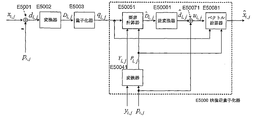
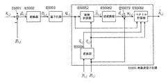
- the converter E5002 and the quantizer E5002 in FIG. 12 are described for the purpose of showing the input / output relationship with the video inverse quantizer E5000 that inversely quantizes the video, that is, the video inverse quantization of the invention.
- the technology can only consist of video inverse quantizer E5000.
- the subtractor E5001 subtracts each element p i, j of the prediction signal vector p from each element x i, j of the video signal vector x to obtain a prediction error value.
- the set of the prediction error values d i, j is referred to as a prediction error value vector d.
- the video inverse quantizer E5000 When the video inverse quantizer E5000 is operated in a frequency conversion unit (for example, 8 ⁇ 8 block unit) described later, the processed element adjacent to the current processing target 8 ⁇ 8 block is used as the prediction signal vector p. Predictive signals generated from can be used.
- the converter E5002 frequency-converts the prediction error value vector d to obtain a conversion coefficient value.
- DCT Discrete Cosine Transform
- the set of D i, j is referred to as a transform coefficient value vector D.
- the quantizer E5003 (which has the same operation as that of the related art of FIG. 1) quantizes each transform coefficient value D i, j obtained by the transformer E5002, and calculates a quantized value q i, j . . If the E5002 quantizer is a linear quantizer with a quantization width of Qs, It becomes.
- the function sign () is a function that returns a sign ( ⁇ ) of a real value input value
- the function floor () is a function that returns the maximum integer among the real value input values.
- the set of the quantized values q i, j is referred to as a quantized value vector q.
- the video inverse quantizer E5000 includes a converter E5004, an element calculator E5005, an inverse converter E5006, an adder E5007, and a vector calculator E5008.
- the input of the video inverse quantizer E5000 is the quantized value vector q, another video signal vector y correlated with the video signal vector x in the frequency domain, and the predicted signal vector p.
- the converter E5004 frequency-converts each of the other video signal vector y and the predicted signal vector, thereby converting the conversion coefficient value vector Y (hereinafter, auxiliary information Y) and the predicted conversion coefficient value vector P.
- the element calculator E5005 receives the quantized value vector q, the auxiliary information Y, and the predicted transform coefficient value vector P as inputs, and performs an inverse quantized transform coefficient value vector. Calculate
- a half-open interval corresponding to the quantized values q i, j is defined as Assuming that the conditional probability density function corresponding to the correlation is f X
- the vector should be calculated.
- the element calculator E5005 obtains a value obtained by subtracting the predicted transformation coefficient value vector P from the auxiliary information Y and the inverse quantization transformation coefficient obtained by the equation (42). Or the half-open interval corresponding to a value obtained by subtracting the predictive transform coefficient value vector P from the auxiliary information Y.
- the inverse quantization transform coefficient calculated by Equation (42) or Equation (42) ' May be updated with the following Expression (43) or Expression (43) ′. It should be noted that the equation (43) or the equation (43) ' When the video signal vector y is a video signal vector in which each element of the video signal vector of the frame adjacent in the time direction is aligned with each element of the video signal vector x by motion compensation prediction, good. That is, the other video signal vector y may be a video signal vector in which each element of the video signal vector of a frame adjacent in the time direction is aligned with each element of the video signal vector x by motion compensation prediction.
- the inverse transformer E5006 is the inverse quantized transform coefficient value vector obtained by the element calculator E5005. Is inverse frequency transformed and the inverse quantization prediction error vector Calculate
- an adder E5007 is provided with the inverse quantization prediction error value vector. Is added to the prediction signal vector p to calculate an initial dequantized video signal vector u. Note that the above-described element calculator E5005 has the inverse quantization transform coefficient. In the embodiment in which a vector obtained by adding the predicted transformation coefficient value vector P to the adder E5007 is supplied to the adder E5007, the adder E5007 is not necessary.
- the vector calculator E5008 oscillates the initial dequantized video signal vector u obtained by the inverse transformer E5006 based on the quantized value vector q, the auxiliary information Y, and the predicted transform coefficient value vector P. Update the de-quantized video signal vector with less Output as.
- the vector calculator E5008 includes the quantized value q i, j , the auxiliary information element Y i, j , the predicted transformation coefficient value vector element P i, j , and the conditional probability density function f X
- Y is the range of each conversion coefficient value D i, j Is calculated by the following equations (44) and (45).
- min_x the probability density function f X the conditional
- min_x and max_x may be calculated from the standard deviation of the conditional probability density function fX
- the range of transform coefficient values x i, j obtained by Equation (44) and Equation (45) And a partial vector space defined by the corresponding element P i, j of the predictive transformation coefficient value vector P
- the partial vector space U is a value range in the frequency domain of the original video signal vector x.
- the vector calculator E5008 is a predetermined number of times K, the initial inverse quantization video signal vector u (hereinafter, u 0 and write) as starting point, sequentially repeating the projection from the first to describe the fourth below From the partial vector space U, an inverse quantized video signal vector with less vibration is calculated.
- k corresponds to the sequential number of repetitions of a certain point in time
- the inverse quantization at the time u k is said sequential repetition has been applied k times the superscript u k described below (superscript)
- U 0 is an initial dequantized video signal vector.
- Said first projection is an inverse quantization video signal vector u k to be inputted, a process of updating more dequantized video signal vector u k + 1 small vibration.
- an objective function J (s) that is a total variation norm defined by the following equation (46) and a constraint function G (s, u k , ⁇ ) defined by the following equation (49):
- the video signal vector s that minimizes the functional F (s, u k , ⁇ ) of the formula (50) that is the sum of the above and s is calculated, and the solution s is set to u k + 1 .
- the result of the first projection (u k + 1 ) is obtained by calculating: (In other words, the objective function J (s) is minimized under the constraint function G (s, u k , ⁇ ), and s having a small total variation norm is obtained. .)
- a sub-gradient method such as Non-Patent Document 6 or a projection method such as Non-Patent Document 7 may be used.
- the above-described ⁇ may be a positive real number depending on the quantization width Qs.
- the second projection projects the inverse quantized video signal vector uk + 1 to the frequency domain. Specifically, as in the case of the converter E5004, u k + 1 is frequency-transformed into the frequency domain to calculate an inverse quantization transform coefficient value vector U k + 1 .
- the third projection is a process of limiting the input inverse quantization transform coefficient value vector U k + 1 to the partial vector space U. Specifically, the following formula is applied to all elements U ij .
- the inverse quantization transform coefficient value vector U k + 1 is projected onto the spatial domain. Specifically, in the same manner as the inverse transformer E5006, U k + 1 is subjected to inverse frequency transformation to calculate an inverse quantized video signal vector u k + 1 .
- the vector calculator E5008 calculates u K obtained by sequentially repeating the first to fourth projections described above K times as the final dequantized video signal vector. Output as.
- step S5001 the above-described converter E5004, element calculator E5005, inverse transformer E5006, and adder E5007 calculate the initial inverse quantized video signal vector u. Subsequently, the process proceeds to step S5002.
- step S5002 the partial vector space U is calculated by the vector calculator E5008 described above. Subsequently, the process proceeds to step S5003.
- step S5003 the vector calculator E5008 described above, the first projection as described above the current inverse quantized video signal vector u k, is updated more dequantized video signal vector u k + 1 small vibration. Subsequently, the process proceeds to step S5004.
- step S5004 the vector calculator E5008 described above converts the inverse quantized video signal vector uk + 1 obtained in step S5003 into the frequency domain by the second projection described above. Subsequently, the process proceeds to step S5005.
- step S5005 the vector calculator E5008 described above restricts the inverse quantization transform coefficient value vector U k + 1 obtained in step S5004 to the partial vector space U by the third projection described above. Subsequently, the process proceeds to step S5006.
- step S5006 the vector calculator E5008 described above projects the inverse quantization transform coefficient value vector U k + 1 obtained in step S5005 onto the spatial domain by the fourth projection described above. Subsequently, the process proceeds to step S5007.
- step S5007 it is determined whether the counter k is equal to a predetermined value K. If they are equal, the process is terminated. Otherwise, the counter k is incremented by 1, and the process returns to step S5003. When returning to step S5003, it is desirable to change the first projection variable ⁇ described above to a smaller positive value.
- each vector calculator calculates the partial vector space U more accurately using auxiliary information. However, it is also possible to calculate without using auxiliary information. Drawings corresponding to the respective embodiments are shown in FIGS. 14, 15, 16, and 17 below.
- the partial vector space U is not accurate, it is desirable that the final dequantized video vector does not vary as much as possible from the initial dequantized video vector obtained by each element calculator.
- the initial value of ⁇ of the functional F (s, u k , ⁇ ) in the first projection in each vector calculator is set smaller than those in the first to fourth embodiments. .
- the initial dequantized video is calculated by using the auxiliary information in each element calculator, but the auxiliary information is not used in the element calculator (simply the inverse quantum). It is conceivable to calculate the initial dequantized image (by using the quantization). Drawings corresponding to the respective embodiments are shown in FIGS. 18, 19, 20, and 21 below.
- the initial dequantized video is not accurate, it is desirable to vary the initial dequantized video vector obtained by each element calculator more.
- the initial value of ⁇ of the functional F (s, u k , ⁇ ) in the first projection in each vector calculator is set larger than those in the first to fourth embodiments. Alternatively, the number of sequential repetitions K is increased.
- a bilateral filter may be used instead of the total variation minimization method.
- Result of bilateral filter for certain element I i, j of video signal Is defined by the following equation.
- ⁇ S and ⁇ r are parameters of the bilateral filter that determines the shape of the two-dimensional Gaussian kernel of Equation (52), and w is a parameter that determines the window size of the bilateral filter.
- ⁇ r may be set according to the estimated quantization noise, and it is desirable to gradually reduce the value during the successive iterations.
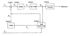
- FIG. 22 shows a configuration diagram of a video encoder using the video inverse quantizer of the fourth embodiment.
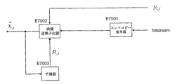
- FIG. 23 shows a configuration diagram of a video decoder using the video inverse quantizer of the fourth embodiment.
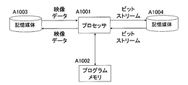
- the information processing system shown in FIG. 24 includes a processor A1001, a program memory A1002, and storage media A1003 and A1004.
- the storage media A1003 and A1004 may be separate storage media, or may be storage areas composed of the same storage medium.
- a magnetic storage medium such as a hard disk can be used as the storage medium.
- the invention relates to an inverse-quantized video signal vector (initial inverse-quantized video signal vector) that has been inverse-quantized element by element according to related technology, and an inverse-quantized video signal vector ( Updated to the final dequantized video signal vector).
- an inverse-quantized video signal vector (initial inverse-quantized video signal vector) that has been inverse-quantized element by element according to related technology
- an inverse-quantized video signal vector Updated to the final dequantized video signal vector.
- the subvector space in which the original video signal vector exists is accurately limited by using the input quantization value, auxiliary information, and the conditional probability density function,
- the final dequantized video signal vector is calculated.
- FIG. 25 shows the result of dequantizing a JPEG-compressed image by simple inverse quantization (normal JPEG expansion), the technique of Non-Patent Document 6, the related technique described above, and the invention technique of the second embodiment described above. is there.
- the horizontal axis of FIG. 25 is PSNR (Peak Signal-Noise Ratio) of normal JPEG decompression, and the vertical axis is PSNR when normal JPEG decompression and inverse quantization are performed by the respective techniques.
- PSNR Peak Signal-Noise Ratio
- Inventive technology suppresses image degradation due to approximate calculation in addition to local degradation of related technology, so that it can be confirmed that PSNR is higher than that of related technology. Further, since the inventive technique accurately limits the partial vector space in which the original video signal vector exists, it can be confirmed that the PSNR is higher than that of Non-Patent Document 6.
- auxiliary information is a video signal vector of a frame adjacent to the video signal vector to be dequantized in the time direction
- a corresponding element of the final dequantized video signal vector is an element of the auxiliary information.
- the invention can provide a higher-quality video encoding method by using it as a local decoding means for an encoded video signal in a video encoding method for encoding a quantized value.
- the invention can provide a higher-quality video decoding method by using it as a quantization value decoding means in a video decoding method for decoding a quantized value.
- a dequantization method comprising: obtaining a set of provisional dequantization values having a minimum total variation norm as a set of dequantization values within a range of possible values for each dequantization value.
- a dequantization method characterized in that a set of provisional inverse quantization values having a minimum total variation norm within a range of possible values is obtained as the set of inverse quantization values.
- An encoding method for encoding a plurality of quantized values Using an inverse quantization method that obtains a set of multiple inverse quantized values by inversely quantizing multiple quantized values as a set, The inverse quantization method includes: For each quantized value, obtain a range of possible values of the inverse quantized value using at least a signal other than the quantized value, A coding method, characterized in that a set of provisional inverse quantized values that minimize the total variation norm within a range of possible values for each inverse quantized value is obtained as the set of inverse quantized values.
- An encoding method for encoding a plurality of quantized values Using an inverse quantization method that obtains a set of multiple inverse quantized values by inversely quantizing multiple quantized values as a set, The inverse quantization method includes: Using the plurality of quantized values and signals other than the quantized values, calculating a provisional inverse quantized value of each quantized value of the quantized values in element units, Using the plurality of quantized values, obtain a range of possible dequantized values for each quantized value, starting with a set of provisional dequantized values calculated in units of elements, and dequantized values
- a coding method comprising: obtaining a set of provisional inverse quantization values having a minimum total variation norm within the range of values that can be taken as the set of inverse quantization values.
- a decoding method for decoding a plurality of quantized values Using an inverse quantization method that obtains a set of multiple inverse quantized values by inversely quantizing multiple quantized values as a set, The inverse quantization method includes: For each quantized value, obtain a range of possible values of the inverse quantized value using at least a signal other than the quantized value, A decoding method characterized in that a set of provisional inverse quantization values having a minimum total variation norm within a range of possible values for each inverse quantization value is obtained as the set of inverse quantization values.
- a decoding method for decoding a plurality of quantized values Using an inverse quantization method that obtains a set of multiple inverse quantized values by inversely quantizing multiple quantized values as a set, The inverse quantization method includes: Using the plurality of quantized values and signals other than the quantized values, calculating a provisional inverse quantized value of each quantized value of the quantized values in element units, Using the plurality of quantized values, obtain a range of possible dequantized values for each quantized value, starting with a set of provisional dequantized values calculated in units of elements, and dequantized values A decoding method, wherein a set of provisional inverse quantized values having a minimum total variation norm within a range of possible values is obtained as the set of inverse quantized values.
- a video inverse quantization method for calculating an inverse quantized video vector from a quantized value vector corresponding to a current video vector to be processed A video element calculation step of calculating an initial dequantized video vector element by element using an element of another video vector having a correlation with the video vector to be processed and an element of the quantized value vector; , The temporary dequantized video vector calculated in the video element calculation step is used as a starting point, and is determined based on another video vector having a correlation with the processing target video vector and the quantized value vector.
- a video vector quantization step comprising: calculating a provisional inverse-quantized video vector having a minimum total variation norm from the set of inverse-quantized video vectors as the inverse-quantized video vector. .
- a video inverse quantization method for calculating an inverse quantized video vector from a quantized value vector corresponding to a current video vector to be processed A video element calculation step of calculating an initial dequantized video vector element by element using an element of another video vector having a correlation with the video vector to be processed and an element of the quantized value vector; , From the set of provisional inverse-quantized video vectors determined by the quantized value vector, starting from the initial inverse-quantized video vector calculated in the video element calculation step, the provisional inverse quantum that minimizes the total variational norm And a video vector calculating step of calculating a quantized video vector as the dequantized video vector.
- a video inverse quantization method for calculating an inverse quantized video vector from a quantized value vector corresponding to a current video vector to be processed A video element calculation step of calculating an initial dequantized video vector element by element using elements of the quantized value vector; The temporary dequantized video vector calculated in the video element calculation step is used as a starting point, and is determined based on another video vector having a correlation with the processing target video vector and the quantized value vector.
- a video vector quantization step comprising: calculating a provisional inverse-quantized video vector having a minimum total variation norm from the set of inverse-quantized video vectors as the inverse-quantized video vector. .
- a video encoding method for encoding a quantized value vector Using a video inverse quantization method that calculates the inverse quantized video vector from the quantized value vector corresponding to the current video vector to be processed,
- the video inverse quantization method includes: Video that calculates the initial dequantized video vector to be processed in element units using the elements of other video vectors that have a correlation with the video vector to be processed and the elements of the quantized value vector An element calculation step; A vector determined by the quantized value vector and another video vector having a correlation with the processing target video vector, starting from the initial dequantized video vector calculated in the video element calculating step And a video vector calculation step of calculating a provisional inverse quantized video vector having a minimum total variation norm from the space as the inverse quantized video vector.
- a video decoding method for decoding a quantized value vector Using a video inverse quantization method that calculates the inverse quantized video vector from the quantized value vector corresponding to the current video vector to be processed,
- the video inverse quantization method includes: Video that calculates the initial dequantized video vector to be processed in element units using the elements of other video vectors that have a correlation with the video vector to be processed and the elements of the quantized value vector An element calculation step; A vector determined by the quantized value vector and another video vector having a correlation with the processing target video vector, starting from the initial dequantized video vector calculated in the video element calculating step
- a video decoding method comprising: a video vector calculation step of calculating a provisional inverse quantized video vector having a minimum total variation norm from the space as the inverse quantized video vector.
- An inverse quantization apparatus that obtains a set of a plurality of inverse quantized values by inversely quantizing a plurality of quantized values as a set, For each quantized value, obtain a range of values that can be taken by the inverse quantized value using at least a signal other than the quantized value, and within the range of values that can be taken for each inverse quantized value, the total variation norm is minimum.
- An inverse quantization apparatus comprising: a restoration unit that obtains a set of provisional inverse quantization values as the set of inverse quantization values.
- the restoration means includes Means for calculating a provisional inverse quantized value of each quantized value of the quantized values in element units using the quantized values and signals other than the quantized values; Using the plurality of quantized values and signals other than the quantized values to obtain a range of values that can be taken for each quantized value, a set of provisional inverse quantized values calculated in units of the elements And a means for obtaining a set of provisional inverse quantized values that minimize the total variation norm within the range of possible values for each inverse quantized value as the set of inverse quantized values.
- the inverse quantization apparatus according to appendix 16, which is characterized.
- the restoration means includes Means for calculating a provisional inverse quantization value of each quantization value of the plurality of quantization values in units of elements using the plurality of quantization values; Using the plurality of quantized values and signals other than the quantized values to obtain a range of values that can be taken for each quantized value, a set of provisional inverse quantized values calculated in units of the elements And a means for obtaining a set of provisional inverse quantized values that minimize the total variation norm within the range of possible values for each inverse quantized value as the set of inverse quantized values.
- Item 17 The inverse quantization apparatus according to appendix 16, which is characterized.
- An inverse quantization apparatus that obtains a set of a plurality of inverse quantized values by inversely quantizing a plurality of quantized values as a set, Using the plurality of quantized values and signals other than the quantized values, a provisional inverse quantized value of each quantized value of the quantized values is calculated in element units, and the quantized values are calculated. The range of values that can be taken by dequantized values for each quantized value is obtained, and the range of values that can be taken by each dequantized value starting from the set of provisional dequantized values calculated in units of elements.
- An inverse quantization apparatus comprising: a restoration unit that obtains a set of provisional inverse quantization values having a minimum total variation norm as the set of inverse quantization values.
- the restoration unit is different from the signal other than the quantized value.
- 20 The inverse quantization apparatus according to any one of appendix 16 to appendix 19, wherein a provisional inverse quantized value with a small value is included in the set of the plurality of inverse quantized values.
- An encoding device for encoding a plurality of quantized values, Having a dequantization device for dequantizing a plurality of quantized values as a set to obtain a set of a plurality of dequantized values;
- the inverse quantization device includes: For each quantized value, obtain a range of values that can be taken by the inverse quantized value using at least a signal other than the quantized value.
- An encoding apparatus comprising: means for obtaining a set of provisional inverse quantized values as the set of inverse quantized values.
- An encoding device for encoding a plurality of quantized values Having a dequantization device for dequantizing a plurality of quantized values as a set to obtain a set of a plurality of dequantized values;
- the inverse quantization device includes: Using the plurality of quantized values and signals other than the quantized values, a provisional inverse quantized value of each quantized value of the quantized values is calculated in element units, and the quantized values are calculated.
- the range of possible values of dequantized values for each quantized value is obtained, and the range of possible values for each dequantized value starting from the set of provisional dequantized values calculated in units of elements.
- a decoding device for decoding a plurality of quantized values Having a dequantization device for dequantizing a plurality of quantized values as a set to obtain a set of a plurality of dequantized values;
- the inverse quantization device includes: For each quantized value, obtain a range of values that can be taken by the inverse quantized value using at least a signal other than the quantized value.
- a decoding apparatus comprising means for obtaining a set of provisional inverse quantized values as the set of inverse quantized values.
- a decoding device for decoding a plurality of quantized values Having a dequantization device for dequantizing a plurality of quantized values as a set to obtain a set of a plurality of dequantized values;
- the inverse quantization device includes: Using the plurality of quantized values and signals other than the quantized values, a provisional inverse quantized value of each quantized value of the quantized values is calculated in element units, and the quantized values are calculated.
- the range of possible values of dequantized values for each quantized value is obtained, and the range of possible values for each dequantized value starting from the set of provisional dequantized values calculated in units of elements.
- a video inverse quantization apparatus that calculates a dequantized video vector from a quantized value vector corresponding to a current video vector to be processed, Video element calculation means for calculating an initial dequantized video vector element by element using an element of another video vector having a correlation with the video vector to be processed and an element of the quantized value vector; , The temporary dequantized video vector calculated by the video element calculation means is used as a starting point, and is determined based on another video vector having a correlation with the processing target video vector and the quantized value vector.
- Video dequantization apparatus comprising video vector calculation means for calculating a provisional inverse quantized video vector having a minimum total variation norm as the inverse quantized video vector from a set of inverse quantized video vectors .
- a video inverse quantization apparatus for calculating an inverse quantized video vector from a quantized value vector corresponding to a current video vector to be processed, Video element calculation means for calculating an initial dequantized video vector element by element using an element of another video vector having a correlation with the video vector to be processed and an element of the quantized value vector; , From the set of provisional inverse-quantized video vectors determined by the quantized value vector, starting from the initial inverse-quantized video vector calculated by the video element calculation means, the provisional inverse quantum that minimizes the total variational norm
- a video dequantization apparatus comprising: video vector calculation means for calculating a quantized video vector as the dequantized video vector.
- a video inverse quantization apparatus for calculating an inversely quantized video vector from a quantized value vector corresponding to a current video vector to be processed, Video element calculation means for calculating an initial dequantized video vector element by element using elements of the quantized value vector; The temporary dequantized video vector calculated by the video element calculation means is used as a starting point, and is determined based on another video vector having a correlation with the processing target video vector and the quantized value vector.
- Video dequantization apparatus comprising video vector calculation means for calculating a provisional inverse quantized video vector having a minimum total variation norm as the inverse quantized video vector from a set of inverse quantized video vectors .
- the video vector calculation means calculates the correlation with respect to the element.
- a video encoding device for encoding a quantized value vector A video inverse quantization device that calculates a dequantized video vector from a quantized value vector corresponding to a current video vector to be processed;
- the video inverse quantization device Video that calculates the initial dequantized video vector to be processed in element units using the elements of other video vectors that have a correlation with the video vector to be processed and the elements of the quantized value vector Element calculation means;
- a video encoding apparatus comprising: a video vector calculation means for calculating a provisional inverse quantized video vector having a minimum total variation norm from the space as the inverse quantized video vector.
- a video decoding device for decoding a quantized value vector A video inverse quantization device that calculates a dequantized video vector from a quantized value vector corresponding to a current video vector to be processed;
- the video inverse quantization device Video that calculates the initial dequantized video vector to be processed in element units using the elements of other video vectors that have a correlation with the video vector to be processed and the elements of the quantized value vector Element calculation means;
- a video decoding apparatus comprising: a video vector calculating means for calculating a provisional inverse quantized video vector having a minimum total variation norm from the space as the inverse quantized video vector.
- An inverse quantization program for inversely quantizing a plurality of quantized values as a set to obtain a set of a plurality of inverse quantized values, Processing for obtaining a range of values that can be taken by the inverse quantization value for each quantization value using at least a signal other than the quantization value; Causing the information processing apparatus to execute a process of obtaining a set of provisional inverse quantization values having a minimum total variation norm as the set of inverse quantization values within a range of possible values for each inverse quantization value.
- the inverse quantization process is: Processing for obtaining a range of values that can be taken by the inverse quantization value for each quantization value using at least a signal other than the quantization value; Causing the information processing apparatus to execute a process of obtaining a set of provisional inverse quantization values having a minimum total variation norm as the set of inverse quantization values within a range of possible values for each inverse quantization value.
- the inverse quantization process is: Using the plurality of quantized values and signals other than the quantized values, a process of calculating a provisional inverse quantized value of each quantized value of the quantized values in element units; Using the plurality of quantized values, obtain a range of possible dequantized values for each quantized value, starting with a set of provisional dequantized values calculated in units of elements, and dequantized values
- the inverse quantization process is: Processing for obtaining a range of values that can be taken by the inverse quantization value for each quantization value using at least a signal other than the quantization value; Causing the information processing apparatus to execute a process of obtaining a set of provisional inverse quantization values having a minimum total variation norm as the set of inverse quantization values within a range of possible values for each inverse quantization value.
- the inverse quantization process is: Using the plurality of quantized values and signals other than the quantized values, a process of calculating a provisional inverse quantized value of each quantized value of the quantized values in element units; Using the plurality of quantized values, obtain a range of possible dequantized values for each quantized value, starting with a set of provisional dequantized values calculated in units of elements, and dequantized values
- a video inverse quantization program for calculating an inverse quantized video vector from a quantized value vector corresponding to a current video vector to be processed, A video element calculation process for calculating an initial dequantized video vector element by element using an element of another video vector having a correlation with the video vector to be processed and an element of the quantized value vector; , The temporary dequantized video vector calculated in the video element calculation process is used as a starting point, and is determined based on another video vector having a correlation with the video vector to be processed and the quantized value vector.
- An information processing apparatus is configured to cause an information processing device to execute a video vector calculation process for calculating a provisional inverse quantized video vector having a minimum total variation norm as the inverse quantized video vector from a set of inverse quantized video vectors. program.
- a video inverse quantization program for calculating a dequantized video vector from a quantized value vector corresponding to a current video vector to be processed A video element calculation process for calculating an initial dequantized video vector element by element using an element of another video vector having a correlation with the video vector to be processed and an element of the quantized value vector; , From the set of provisional inverse-quantized video vectors determined by the quantized value vector, starting from the initial inverse-quantized video vector calculated in the video element calculation process, the provisional inverse quantum that minimizes the total variational norm
- a video inverse quantization program for calculating an inverse quantized video vector from a quantized value vector corresponding to a current video vector to be processed, Video element calculation processing for calculating an initial dequantized video vector element by element using the quantized value vector elements;
- the temporary dequantized video vector calculated in the video element calculation process is used as a starting point, and is determined based on another video vector having a correlation with the video vector to be processed and the quantized value vector.
- An information processing apparatus is configured to cause an information processing device to execute a video vector calculation process for calculating a provisional inverse quantized video vector having a minimum total variation norm as the inverse quantized video vector from a set of inverse quantized video vectors. program.
- a video encoding program for encoding a quantized value vector A video inverse quantization process for calculating the inverse quantized video vector from the quantized value vector corresponding to the current video vector to be processed;
- the video inverse quantization process is: Video that calculates the initial dequantized video vector to be processed in element units using the elements of other video vectors that have a correlation with the video vector to be processed and the elements of the quantized value vector Element calculation processing, A vector determined by the quantized value vector and another video vector having a correlation with the processing target video vector, starting from the initial dequantized video vector calculated in the video element calculation process
- a video decoding program for decoding a quantized value vector A video inverse quantization process for calculating the inverse quantized video vector from the quantized value vector corresponding to the current video vector to be processed;
- the video inverse quantization process is: Video that calculates the initial dequantized video vector to be processed in element units using the elements of other video vectors that have a correlation with the video vector to be processed and the elements of the quantized value vector Element calculation processing, A vector determined by the quantized value vector and another video vector having a correlation with the processing target video vector, starting from the initial dequantized video vector calculated in the video element calculation process
Landscapes
- Engineering & Computer Science (AREA)
- Multimedia (AREA)
- Signal Processing (AREA)
- Theoretical Computer Science (AREA)
- Compression, Expansion, Code Conversion, And Decoders (AREA)
- Compression Or Coding Systems Of Tv Signals (AREA)
- Compression Of Band Width Or Redundancy In Fax (AREA)
Abstract
Description




















図6を参照して、本実施形態における発明の映像逆量子化技術の構成について説明する。ただし、図6の量子化器E2001は、映像を逆量子化する映像逆量子化器E2000との入出力関係を示す目的で記載していること、すなわち、発明の映像逆量子化技術は映像逆量子化器E2000のみによって構成できることに注意されたい。









ベクトル計算器E2003は、入力される補助情報yと量子化値ベクトルqとに基づいて、入力される初期逆量子化映像信号ベクトルuをより振動の少ない逆量子化映像信号ベクトル更新して、その更新の結果を最終逆量子化映像信号ベクトル












<第2の実施の形態>
本実施形態では、映像逆量子化器の入力である量子化値が、映像信号ベクトルを周波数変換した変換係数の量子化値である場合の本発明の映像逆量子化器について説明する。














続いて、逆変換器E3005は、前記要素計算器E3004で得られた逆量子化変換係数値ベクトル
















<第3の実施の形態>
本実施形態では、映像逆量子化器の入力である量子化値が、映像信号ベクトルが予測された予測誤差値の量子化値である場合の本発明の映像逆量子化器について説明する。






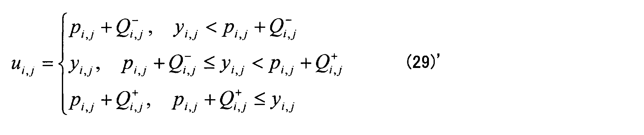


















<第4の実施の形態>
本実施形態では、映像逆量子化器の入力である量子化値が、映像信号ベクトルが予測された予測誤差を周波数変換した変換係数の量子化値である場合の本発明の映像逆量子化器について説明する。

























ただし、min_xは、前記条件付確率密度関数fX|Yが定義域において0と交わるXの最小値、max_xは、前記条件付確率密度関数fX|Yが定義域において0と交わるXの最大値である。なお、min_xとmax_xとは、前記条件付確率密度関数fX|Yの標準偏差から計算してもよい。











<第5の実施の形態>
上述した実施形態1から4においては、それぞれのベクトル計算器において、補助情報を用いて部分ベクトル空間Uをより正確に計算したが、補助情報を利用しないで計算する形態も考えられる。それぞれの実施形態に対応する図面を以下の図14, 図15, 図16, 図17に示す。この形態においては、部分ベクトル空間Uが正確ではないため、前記最終逆量子化映像ベクトルが、それぞれの要素計算器で得られた初期逆量子化映像ベクトルからなるべく変動しないことが望ましい。そのためには、それぞれのベクトル計算器における、前記第1の射影における汎関数F(s,uk,λ)のλの初期値を、上述した実施形態1から4のものよりもより小さく設定する。




量子化値毎に逆量子化値の取り得る値の範囲を少なくとも前記量子化値以外の信号を用いて求め、
逆量子化値毎の取り得る値の範囲内で、全変分ノルムが最小となる仮逆量子化値の組を前記逆量子化値の組として求める
ことを特徴とする逆量子化方法。
前記複数の量子化値と前記量子化値以外の信号とを用いて量子化値毎に逆量子化値の取り得る値の範囲を求め、前記要素単位で計算された仮逆量子化値の組を始点にして、逆量子化値毎の取り得る値の範囲内で、全変分ノルムが最小となる仮逆量子化値の組を前記逆量子化値の組として求める
ことを特徴とする付記1に記載の逆量子化方法。
前記複数の量子化値と前記量子化値以外の信号とを用いて量子化値毎に逆量子化値の取り得る値の範囲を求め、前記要素単位で計算された仮逆量子化値の組を始点にして、逆量子化値毎の取り得る値の範囲内で、全変分ノルムが最小となる仮逆量子化値の組を前記逆量子化値の組として求める
ことを特徴とする付記1に記載の逆量子化方法。
前記複数の量子化値と前記量子化値以外の信号とを用いて、前記複数の量子化値の各量子化値の仮逆量子化値を要素単位で計算し、
前記複数の量子化値を用いて量子化値毎に逆量子化値の取り得る値の範囲を求め、前記要素単位で計算された仮逆量子化値の組を始点にして、逆量子化値毎の取り得る値の範囲内で、全変分ノルムが最小となる仮逆量子化値の組を前記逆量子化値の組として求める
ことを特徴とする逆量子化方法。
ことを特徴とする付記1から付記4のいずれかに記載の逆量子化方法。
複数の量子化値を組として逆量子化して複数の逆量子化値の組を求める逆量子化方法を用い、
前記逆量子化方法は、
量子化値毎に逆量子化値の取り得る値の範囲を少なくとも前記量子化値以外の信号を用いて求め、
逆量子化値毎の取り得る値の範囲内で、全変分ノルムが最小となる仮逆量子化値の組を前記逆量子化値の組として求める
ことを特徴とする符号化方法。
複数の量子化値を組として逆量子化して複数の逆量子化値の組を求める逆量子化方法を用い、
前記逆量子化方法は、
前記複数の量子化値と前記量子化値以外の信号とを用いて、前記複数の量子化値の各量子化値の仮逆量子化値を要素単位で計算し、
前記複数の量子化値を用いて量子化値毎に逆量子化値の取り得る値の範囲を求め、前記要素単位で計算された仮逆量子化値の組を始点にして、逆量子化値毎の取り得る値の範囲内で、全変分ノルムが最小となる仮逆量子化値の組を前記逆量子化値の組として求める
ことを特徴とする符号化方法。
複数の量子化値を組として逆量子化して複数の逆量子化値の組を求める逆量子化方法を用い、
前記逆量子化方法は、
量子化値毎に逆量子化値の取り得る値の範囲を少なくとも前記量子化値以外の信号を用いて求め、
逆量子化値毎の取り得る値の範囲内で、全変分ノルムが最小となる仮逆量子化値の組を前記逆量子化値の組として求める
ことを特徴とする復号方法。
複数の量子化値を組として逆量子化して複数の逆量子化値の組を求める逆量子化方法を用い、
前記逆量子化方法は、
前記複数の量子化値と前記量子化値以外の信号とを用いて、前記複数の量子化値の各量子化値の仮逆量子化値を要素単位で計算し、
前記複数の量子化値を用いて量子化値毎に逆量子化値の取り得る値の範囲を求め、前記要素単位で計算された仮逆量子化値の組を始点にして、逆量子化値毎の取り得る値の範囲内で、全変分ノルムが最小となる仮逆量子化値の組を前記逆量子化値の組として求める
ことを特徴とする復号方法。
前記処理対象の映像ベクトルとの間に相関が存在する他の映像ベクトルの要素と、前記量子化値ベクトルの要素とを用いて初期逆量子化映像ベクトルを要素単位で計算する映像要素計算ステップと、
前記映像要素計算ステップにて計算された初期逆量子化映像ベクトルを始点にして、前記処理対象の映像ベクトルとの間に相関が存在する他の映像ベクトルと前記量子化値ベクトルとによって決定する仮逆量子化映像ベクトルの集合から、全変分ノルムが最小となる仮逆量子化映像ベクトルを前記逆量子化映像ベクトルとして計算する映像ベクトル計算ステップと
を有することを特徴とする映像逆量子化方法。
前記処理対象の映像ベクトルとの間に相関が存在する他の映像ベクトルの要素と、前記量子化値ベクトルの要素とを用いて初期逆量子化映像ベクトルを要素単位で計算する映像要素計算ステップと、
前記映像要素計算ステップにて計算された初期逆量子化映像ベクトルを始点にして、前記量子化値ベクトルによって決定する仮逆量子化映像ベクトルの集合から、全変分ノルムが最小となる仮逆量子化映像ベクトルを前記逆量子化映像ベクトルとして計算する映像ベクトル計算ステップと
を有することを特徴とする映像逆量子化方法。
前記量子化値ベクトルの要素を用いて初期逆量子化映像ベクトルを要素単位で計算する映像要素計算ステップと、
前記映像要素計算ステップにて計算された初期逆量子化映像ベクトルを始点にして、前記処理対象の映像ベクトルとの間に相関が存在する他の映像ベクトルと前記量子化値ベクトルとによって決定する仮逆量子化映像ベクトルの集合から、全変分ノルムが最小となる仮逆量子化映像ベクトルを前記逆量子化映像ベクトルとして計算する映像ベクトル計算ステップと
を有することを特徴とする映像逆量子化方法。
現在の処理対象の映像ベクトルに対応する量子化値ベクトルからその逆量子化映像ベクトルを計算する映像逆量子化方法を用い、
前記映像逆量子化方法は、
前記処理対象の映像ベクトルとの間に相関が存在する他の映像ベクトルの要素と、前記量子化値ベクトルの要素とを用いて前記処理対象の初期逆量子化映像ベクトルを要素単位で計算する映像要素計算ステップと、
前記映像要素計算ステップにて計算された初期逆量子化映像ベクトルを始点にして、前記処理対象の映像ベクトルとの間に相関が存在する他の映像ベクトルと前記量子化値ベクトルとによって決定するベクトル空間から、全変分ノルムが最小となる仮逆量子化映像ベクトルを前記逆量子化映像ベクトルとして計算する映像ベクトル計算ステップと
を有することを特徴とする映像符号化方法。
現在の処理対象の映像ベクトルに対応する量子化値ベクトルからその逆量子化映像ベクトルを計算する映像逆量子化方法を用い、
前記映像逆量子化方法は、
前記処理対象の映像ベクトルとの間に相関が存在する他の映像ベクトルの要素と、前記量子化値ベクトルの要素とを用いて前記処理対象の初期逆量子化映像ベクトルを要素単位で計算する映像要素計算ステップと、
前記映像要素計算ステップにて計算された初期逆量子化映像ベクトルを始点にして、前記処理対象の映像ベクトルとの間に相関が存在する他の映像ベクトルと前記量子化値ベクトルとによって決定するベクトル空間から、全変分ノルムが最小となる仮逆量子化映像ベクトルを前記逆量子化映像ベクトルとして計算する映像ベクトル計算ステップと
を有することを特徴とする映像復号方法。
量子化値毎に逆量子化値の取り得る値の範囲を少なくとも前記量子化値以外の信号を用いて求め、逆量子化値毎の取り得る値の範囲内で、全変分ノルムが最小となる仮逆量子化値の組を前記逆量子化値の組として求める復元手段
を有することを特徴とする逆量子化装置。
前記複数の量子化値と前記量子化値以外の信号とを用いて、前記複数の量子化値の各量子化値の仮逆量子化値を要素単位で計算する手段と、
前記複数の量子化値と前記量子化値以外の信号とを用いて量子化値毎に逆量子化値の取り得る値の範囲を求め、前記要素単位で計算された仮逆量子化値の組を始点にして、逆量子化値毎の取り得る値の範囲内で、全変分ノルムが最小となる仮逆量子化値の組を前記逆量子化値の組として求める手段と
を有することを特徴とする付記16に記載の逆量子化装置。
前記複数の量子化値を用いて、前記複数の量子化値の各量子化値の仮逆量子化値を要素単位で計算する手段と、
前記複数の量子化値と前記量子化値以外の信号とを用いて量子化値毎に逆量子化値の取り得る値の範囲を求め、前記要素単位で計算された仮逆量子化値の組を始点にして、逆量子化値毎の取り得る値の範囲内で、全変分ノルムが最小となる仮逆量子化値の組を前記逆量子化値の組として求める手段と
を有することを特徴とする付記16に記載の逆量子化装置。
前記複数の量子化値と前記量子化値以外の信号とを用いて、前記複数の量子化値の各量子化値の仮逆量子化値を要素単位で計算し、前記複数の量子化値を用いて量子化値毎に逆量子化値の取り得る値の範囲を求め、前記要素単位で計算された仮逆量子化値の組を始点にして、逆量子化値毎の取り得る値の範囲内で、全変分ノルムが最小となる仮逆量子化値の組を前記逆量子化値の組として求める復元手段
を有することを特徴とする逆量子化装置。
ことを特徴とする付記16から付記19のいずれかに記載の逆量子化装置。
複数の量子化値を組として逆量子化して複数の逆量子化値の組を求める逆量子化装置を有し、
前記逆量子化装置は、
量子化値毎に逆量子化値の取り得る値の範囲を少なくとも前記量子化値以外の信号を用いて求め、逆量子化値毎の取り得る値の範囲内で、全変分ノルムが最小となる仮逆量子化値の組を前記逆量子化値の組として求める手段を有する
ことを特徴とする符号化装置。
複数の量子化値を組として逆量子化して複数の逆量子化値の組を求める逆量子化装置を有し、
前記逆量子化装置は、
前記複数の量子化値と前記量子化値以外の信号とを用いて、前記複数の量子化値の各量子化値の仮逆量子化値を要素単位で計算し、前記複数の量子化値を用いて量子化値毎に逆量子化値の取り得る値の範囲を求め、前記要素単位で計算された仮逆量子化値の組を始点にして、逆量子化値毎の取り得る値の範囲内で、全変分ノルムが最小となる仮逆量子化値の組を前記逆量子化値の組として求める手段を有する
ことを特徴とする符号化装置。
複数の量子化値を組として逆量子化して複数の逆量子化値の組を求める逆量子化装置を有し、
前記逆量子化装置は、
量子化値毎に逆量子化値の取り得る値の範囲を少なくとも前記量子化値以外の信号を用いて求め、逆量子化値毎の取り得る値の範囲内で、全変分ノルムが最小となる仮逆量子化値の組を前記逆量子化値の組として求める手段を有する
ことを特徴とする復号装置。
複数の量子化値を組として逆量子化して複数の逆量子化値の組を求める逆量子化装置を有し、
前記逆量子化装置は、
前記複数の量子化値と前記量子化値以外の信号とを用いて、前記複数の量子化値の各量子化値の仮逆量子化値を要素単位で計算し、前記複数の量子化値を用いて量子化値毎に逆量子化値の取り得る値の範囲を求め、前記要素単位で計算された仮逆量子化値の組を始点にして、逆量子化値毎の取り得る値の範囲内で、全変分ノルムが最小となる仮逆量子化値の組を前記逆量子化値の組として求める手段を有する
ことを特徴とする復号装置。
前記処理対象の映像ベクトルとの間に相関が存在する他の映像ベクトルの要素と、前記量子化値ベクトルの要素とを用いて初期逆量子化映像ベクトルを要素単位で計算する映像要素計算手段と、
前記映像要素計算手段にて計算された初期逆量子化映像ベクトルを始点にして、前記処理対象の映像ベクトルとの間に相関が存在する他の映像ベクトルと前記量子化値ベクトルとによって決定する仮逆量子化映像ベクトルの集合から、全変分ノルムが最小となる仮逆量子化映像ベクトルを前記逆量子化映像ベクトルとして計算する映像ベクトル計算手段と
を有することを特徴とする映像逆量子化装置。
前記処理対象の映像ベクトルとの間に相関が存在する他の映像ベクトルの要素と、前記量子化値ベクトルの要素とを用いて初期逆量子化映像ベクトルを要素単位で計算する映像要素計算手段と、
前記映像要素計算手段にて計算された初期逆量子化映像ベクトルを始点にして、前記量子化値ベクトルによって決定する仮逆量子化映像ベクトルの集合から、全変分ノルムが最小となる仮逆量子化映像ベクトルを前記逆量子化映像ベクトルとして計算する映像ベクトル計算手段と
を有することを特徴とする映像逆量子化装置。
前記量子化値ベクトルの要素を用いて初期逆量子化映像ベクトルを要素単位で計算する映像要素計算手段と、
前記映像要素計算手段にて計算された初期逆量子化映像ベクトルを始点にして、前記処理対象の映像ベクトルとの間に相関が存在する他の映像ベクトルと前記量子化値ベクトルとによって決定する仮逆量子化映像ベクトルの集合から、全変分ノルムが最小となる仮逆量子化映像ベクトルを前記逆量子化映像ベクトルとして計算する映像ベクトル計算手段と
を有することを特徴とする映像逆量子化装置。
現在の処理対象の映像ベクトルに対応する量子化値ベクトルからその逆量子化映像ベクトルを計算する映像逆量子化装置を有し、
前記映像逆量子化装置は、
前記処理対象の映像ベクトルとの間に相関が存在する他の映像ベクトルの要素と、前記量子化値ベクトルの要素とを用いて前記処理対象の初期逆量子化映像ベクトルを要素単位で計算する映像要素計算手段と、
前記映像要素計算手段にて計算された初期逆量子化映像ベクトルを始点にして、前記処理対象の映像ベクトルとの間に相関が存在する他の映像ベクトルと前記量子化値ベクトルとによって決定するベクトル空間から、全変分ノルムが最小となる仮逆量子化映像ベクトルを前記逆量子化映像ベクトルとして計算する映像ベクトル計算手段と
を有することを特徴とする映像符号化装置。
現在の処理対象の映像ベクトルに対応する量子化値ベクトルからその逆量子化映像ベクトルを計算する映像逆量子化装置を有し、
前記映像逆量子化装置は、
前記処理対象の映像ベクトルとの間に相関が存在する他の映像ベクトルの要素と、前記量子化値ベクトルの要素とを用いて前記処理対象の初期逆量子化映像ベクトルを要素単位で計算する映像要素計算手段と、
前記映像要素計算手段にて計算された初期逆量子化映像ベクトルを始点にして、前記処理対象の映像ベクトルとの間に相関が存在する他の映像ベクトルと前記量子化値ベクトルとによって決定するベクトル空間から、全変分ノルムが最小となる仮逆量子化映像ベクトルを前記逆量子化映像ベクトルとして計算する映像ベクトル計算手段と
を有することを特徴とする映像復号装置。
量子化値毎に逆量子化値の取り得る値の範囲を少なくとも前記量子化値以外の信号を用いて求める処理と、
逆量子化値毎の取り得る値の範囲内で、全変分ノルムが最小となる仮逆量子化値の組を前記逆量子化値の組として求める処理と
を情報処理装置に実行させることを特徴とするプログラム。
前記複数の量子化値と前記量子化値以外の信号とを用いて、前記複数の量子化値の各量子化値の仮逆量子化値を要素単位で計算する処理と、
前記複数の量子化値を用いて量子化値毎に逆量子化値の取り得る値の範囲を求め、前記要素単位で計算された仮逆量子化値の組を始点にして、逆量子化値毎の取り得る値の範囲内で、全変分ノルムが最小となる仮逆量子化値の組を前記逆量子化値の組として求める処理と
を情報処理装置に実行させることを特徴とするプログラム。
複数の量子化値を組として逆量子化して複数の逆量子化値の組を求める逆量子化処理を有し、
前記逆量子化処理は、
量子化値毎に逆量子化値の取り得る値の範囲を少なくとも前記量子化値以外の信号を用いて求める処理と、
逆量子化値毎の取り得る値の範囲内で、全変分ノルムが最小となる仮逆量子化値の組を前記逆量子化値の組として求める処理と
を情報処理装置に実行させることを特徴とするプログラム。
複数の量子化値を組として逆量子化して複数の逆量子化値の組を求める逆量子化処理を有し、
前記逆量子化処理は、
前記複数の量子化値と前記量子化値以外の信号とを用いて、前記複数の量子化値の各量子化値の仮逆量子化値を要素単位で計算する処理と、
前記複数の量子化値を用いて量子化値毎に逆量子化値の取り得る値の範囲を求め、前記要素単位で計算された仮逆量子化値の組を始点にして、逆量子化値毎の取り得る値の範囲内で、全変分ノルムが最小となる仮逆量子化値の組を前記逆量子化値の組として求める処理と
を情報処理装置に実行させることを特徴とするプログラム。
複数の量子化値を組として逆量子化して複数の逆量子化値の組を求める逆量子化処理を有し、
前記逆量子化処理は、
量子化値毎に逆量子化値の取り得る値の範囲を少なくとも前記量子化値以外の信号を用いて求める処理と、
逆量子化値毎の取り得る値の範囲内で、全変分ノルムが最小となる仮逆量子化値の組を前記逆量子化値の組として求める処理と
を情報処理装置に実行させることを特徴とするプログラム。
複数の量子化値を組として逆量子化して複数の逆量子化値の組を求める逆量子化処理を有し、
前記逆量子化処理は、
前記複数の量子化値と前記量子化値以外の信号とを用いて、前記複数の量子化値の各量子化値の仮逆量子化値を要素単位で計算する処理と、
前記複数の量子化値を用いて量子化値毎に逆量子化値の取り得る値の範囲を求め、前記要素単位で計算された仮逆量子化値の組を始点にして、逆量子化値毎の取り得る値の範囲内で、全変分ノルムが最小となる仮逆量子化値の組を前記逆量子化値の組として求める処理と
を情報処理装置に実行させることを特徴とするプログラム。
前記処理対象の映像ベクトルとの間に相関が存在する他の映像ベクトルの要素と、前記量子化値ベクトルの要素とを用いて初期逆量子化映像ベクトルを要素単位で計算する映像要素計算処理と、
前記映像要素計算処理にて計算された初期逆量子化映像ベクトルを始点にして、前記処理対象の映像ベクトルとの間に相関が存在する他の映像ベクトルと前記量子化値ベクトルとによって決定する仮逆量子化映像ベクトルの集合から、全変分ノルムが最小となる仮逆量子化映像ベクトルを前記逆量子化映像ベクトルとして計算する映像ベクトル計算処理と
を情報処理装置に実行させることを特徴とするプログラム。
前記処理対象の映像ベクトルとの間に相関が存在する他の映像ベクトルの要素と、前記量子化値ベクトルの要素とを用いて初期逆量子化映像ベクトルを要素単位で計算する映像要素計算処理と、
前記映像要素計算処理にて計算された初期逆量子化映像ベクトルを始点にして、前記量子化値ベクトルによって決定する仮逆量子化映像ベクトルの集合から、全変分ノルムが最小となる仮逆量子化映像ベクトルを前記逆量子化映像ベクトルとして計算する映像ベクトル計算処理と
を情報処理装置に実行させることを特徴とするプログラム。
前記量子化値ベクトルの要素を用いて初期逆量子化映像ベクトルを要素単位で計算する映像要素計算処理と、
前記映像要素計算処理にて計算された初期逆量子化映像ベクトルを始点にして、前記処理対象の映像ベクトルとの間に相関が存在する他の映像ベクトルと前記量子化値ベクトルとによって決定する仮逆量子化映像ベクトルの集合から、全変分ノルムが最小となる仮逆量子化映像ベクトルを前記逆量子化映像ベクトルとして計算する映像ベクトル計算処理と
を情報処理装置に実行させることを特徴とするプログラム。
現在の処理対象の映像ベクトルに対応する量子化値ベクトルからその逆量子化映像ベクトルを計算する映像逆量子化処理を有し、
前記映像逆量子化処理は、
前記処理対象の映像ベクトルとの間に相関が存在する他の映像ベクトルの要素と、前記量子化値ベクトルの要素とを用いて前記処理対象の初期逆量子化映像ベクトルを要素単位で計算する映像要素計算処理と、
前記映像要素計算処理にて計算された初期逆量子化映像ベクトルを始点にして、前記処理対象の映像ベクトルとの間に相関が存在する他の映像ベクトルと前記量子化値ベクトルとによって決定するベクトル空間から、全変分ノルムが最小となる仮逆量子化映像ベクトルを前記逆量子化映像ベクトルとして計算する映像ベクトル計算処理と
を情報処理装置に実行させることを特徴とするプログラム。
現在の処理対象の映像ベクトルに対応する量子化値ベクトルからその逆量子化映像ベクトルを計算する映像逆量子化処理を有し、
前記映像逆量子化処理は、
前記処理対象の映像ベクトルとの間に相関が存在する他の映像ベクトルの要素と、前記量子化値ベクトルの要素とを用いて前記処理対象の初期逆量子化映像ベクトルを要素単位で計算する映像要素計算処理と、
前記映像要素計算処理にて計算された初期逆量子化映像ベクトルを始点にして、前記処理対象の映像ベクトルとの間に相関が存在する他の映像ベクトルと前記量子化値ベクトルとによって決定するベクトル空間から、全変分ノルムが最小となる仮逆量子化映像ベクトルを前記逆量子化映像ベクトルとして計算する映像ベクトル計算処理と
を情報処理装置に実行させることを特徴とするプログラム。
E2001 量子化器
E2002 要素計算器
E2003 ベクトル計算器
Claims (41)
- 複数の量子化値を組として逆量子化して複数の逆量子化値の組を求める逆量子化方法であって、
量子化値毎に逆量子化値の取り得る値の範囲を少なくとも前記量子化値以外の信号を用いて求め、
逆量子化値毎の取り得る値の範囲内で、全変分ノルムが最小となる仮逆量子化値の組を前記逆量子化値の組として求める
ことを特徴とする逆量子化方法。 - 前記複数の量子化値と前記量子化値以外の信号とを用いて、前記複数の量子化値の各量子化値の仮逆量子化値を要素単位で計算し、
前記複数の量子化値と前記量子化値以外の信号とを用いて量子化値毎に逆量子化値の取り得る値の範囲を求め、前記要素単位で計算された仮逆量子化値の組を始点にして、逆量子化値毎の取り得る値の範囲内で、全変分ノルムが最小となる仮逆量子化値の組を前記逆量子化値の組として求める
ことを特徴とする請求項1に記載の逆量子化方法。 - 前記複数の量子化値を用いて、前記複数の量子化値の各量子化値の仮逆量子化値を要素単位で計算し、
前記複数の量子化値と前記量子化値以外の信号とを用いて量子化値毎に逆量子化値の取り得る値の範囲を求め、前記要素単位で計算された仮逆量子化値の組を始点にして、逆量子化値毎の取り得る値の範囲内で、全変分ノルムが最小となる仮逆量子化値の組を前記逆量子化値の組として求める
ことを特徴とする請求項1に記載の逆量子化方法。 - 複数の量子化値を組として逆量子化して複数の逆量子化値の組を求める逆量子化方法であって、
前記複数の量子化値と前記量子化値以外の信号とを用いて、前記複数の量子化値の各量子化値の仮逆量子化値を要素単位で計算し、
前記複数の量子化値を用いて量子化値毎に逆量子化値の取り得る値の範囲を求め、前記要素単位で計算された仮逆量子化値の組を始点にして、逆量子化値毎の取り得る値の範囲内で、全変分ノルムが最小となる仮逆量子化値の組を前記逆量子化値の組として求める
ことを特徴とする逆量子化方法。 - ある前記量子化値以外の信号が対応する量子化値の逆量子化値の取り得る値の範囲に含まれる場合、該前記量子化値以外の信号との差分が小さい仮逆量子化値を前記複数の逆量子化値の組に含める
ことを特徴とする請求項1から請求項4のいずれかに記載の逆量子化方法。 - 複数の量子化値を符号化する符号化方法であって、
複数の量子化値を組として逆量子化して複数の逆量子化値の組を求める逆量子化方法を用い、
前記逆量子化方法は、
量子化値毎に逆量子化値の取り得る値の範囲を少なくとも前記量子化値以外の信号を用いて求め、
逆量子化値毎の取り得る値の範囲内で、全変分ノルムが最小となる仮逆量子化値の組を前記逆量子化値の組として求める
ことを特徴とする符号化方法。 - 複数の量子化値を符号化する符号化方法であって、
複数の量子化値を組として逆量子化して複数の逆量子化値の組を求める逆量子化方法を用い、
前記逆量子化方法は、
前記複数の量子化値と前記量子化値以外の信号とを用いて、前記複数の量子化値の各量子化値の仮逆量子化値を要素単位で計算し、
前記複数の量子化値を用いて量子化値毎に逆量子化値の取り得る値の範囲を求め、前記要素単位で計算された仮逆量子化値の組を始点にして、逆量子化値毎の取り得る値の範囲内で、全変分ノルムが最小となる仮逆量子化値の組を前記逆量子化値の組として求める
ことを特徴とする符号化方法。 - 複数の量子化値を復号する復号方法であって、
複数の量子化値を組として逆量子化して複数の逆量子化値の組を求める逆量子化方法を用い、
前記逆量子化方法は、
量子化値毎に逆量子化値の取り得る値の範囲を少なくとも前記量子化値以外の信号を用いて求め、
逆量子化値毎の取り得る値の範囲内で、全変分ノルムが最小となる仮逆量子化値の組を前記逆量子化値の組として求める
ことを特徴とする復号方法。 - 複数の量子化値を復号する復号方法であって、
複数の量子化値を組として逆量子化して複数の逆量子化値の組を求める逆量子化方法を用い、
前記逆量子化方法は、
前記複数の量子化値と前記量子化値以外の信号とを用いて、前記複数の量子化値の各量子化値の仮逆量子化値を要素単位で計算し、
前記複数の量子化値を用いて量子化値毎に逆量子化値の取り得る値の範囲を求め、前記要素単位で計算された仮逆量子化値の組を始点にして、逆量子化値毎の取り得る値の範囲内で、全変分ノルムが最小となる仮逆量子化値の組を前記逆量子化値の組として求める
ことを特徴とする復号方法。 - 現在の処理対象の映像ベクトルに対応する量子化値ベクトルからその逆量子化映像ベクトルを計算する映像逆量子化方法であって、
前記処理対象の映像ベクトルとの間に相関が存在する他の映像ベクトルの要素と、前記量子化値ベクトルの要素とを用いて初期逆量子化映像ベクトルを要素単位で計算する映像要素計算ステップと、
前記映像要素計算ステップにて計算された初期逆量子化映像ベクトルを始点にして、前記処理対象の映像ベクトルとの間に相関が存在する他の映像ベクトルと前記量子化値ベクトルとによって決定する仮逆量子化映像ベクトルの集合から、全変分ノルムが最小となる仮逆量子化映像ベクトルを前記逆量子化映像ベクトルとして計算する映像ベクトル計算ステップと
を有することを特徴とする映像逆量子化方法。 - 現在の処理対象の映像ベクトルに対応する量子化値ベクトルからその逆量子化映像ベクトルを計算する映像逆量子化方法であって、
前記処理対象の映像ベクトルとの間に相関が存在する他の映像ベクトルの要素と、前記量子化値ベクトルの要素とを用いて初期逆量子化映像ベクトルを要素単位で計算する映像要素計算ステップと、
前記映像要素計算ステップにて計算された初期逆量子化映像ベクトルを始点にして、前記量子化値ベクトルによって決定する仮逆量子化映像ベクトルの集合から、全変分ノルムが最小となる仮逆量子化映像ベクトルを前記逆量子化映像ベクトルとして計算する映像ベクトル計算ステップと
を有することを特徴とする映像逆量子化方法。 - 現在の処理対象の映像ベクトルに対応する量子化値ベクトルからその逆量子化映像ベクトルを計算する映像逆量子化方法であって、
前記量子化値ベクトルの要素を用いて初期逆量子化映像ベクトルを要素単位で計算する映像要素計算ステップと、
前記映像要素計算ステップにて計算された初期逆量子化映像ベクトルを始点にして、前記処理対象の映像ベクトルとの間に相関が存在する他の映像ベクトルと前記量子化値ベクトルとによって決定する仮逆量子化映像ベクトルの集合から、全変分ノルムが最小となる仮逆量子化映像ベクトルを前記逆量子化映像ベクトルとして計算する映像ベクトル計算ステップと
を有することを特徴とする映像逆量子化方法。 - 前記映像ベクトル計算ステップは、前記相関が存在する他の映像ベクトルの要素が、対応する前記仮逆量子化映像ベクトルの集合の要素の値域に含まれる場合、該要素に関して前記相関が存在する他の映像ベクトルの要素との差分がより小さい、仮逆量子化映像ベクトルを前記逆量子化映像ベクトルとして計算することを特徴とする請求項10から請求項12のいずれかに記載の映像逆量子化方法。
- 量子化値ベクトルを符号化する映像符号化方法であって、
現在の処理対象の映像ベクトルに対応する量子化値ベクトルからその逆量子化映像ベクトルを計算する映像逆量子化方法を用い、
前記映像逆量子化方法は、
前記処理対象の映像ベクトルとの間に相関が存在する他の映像ベクトルの要素と、前記量子化値ベクトルの要素とを用いて前記処理対象の初期逆量子化映像ベクトルを要素単位で計算する映像要素計算ステップと、
前記映像要素計算ステップにて計算された初期逆量子化映像ベクトルを始点にして、前記処理対象の映像ベクトルとの間に相関が存在する他の映像ベクトルと前記量子化値ベクトルとによって決定するベクトル空間から、全変分ノルムが最小となる仮逆量子化映像ベクトルを前記逆量子化映像ベクトルとして計算する映像ベクトル計算ステップと
を有することを特徴とする映像符号化方法。 - 量子化値ベクトルを復号する映像復号方法であって、
現在の処理対象の映像ベクトルに対応する量子化値ベクトルからその逆量子化映像ベクトルを計算する映像逆量子化方法を用い、
前記映像逆量子化方法は、
前記処理対象の映像ベクトルとの間に相関が存在する他の映像ベクトルの要素と、前記量子化値ベクトルの要素とを用いて前記処理対象の初期逆量子化映像ベクトルを要素単位で計算する映像要素計算ステップと、
前記映像要素計算ステップにて計算された初期逆量子化映像ベクトルを始点にして、前記処理対象の映像ベクトルとの間に相関が存在する他の映像ベクトルと前記量子化値ベクトルとによって決定するベクトル空間から、全変分ノルムが最小となる仮逆量子化映像ベクトルを前記逆量子化映像ベクトルとして計算する映像ベクトル計算ステップと
を有することを特徴とする映像復号方法。 - 複数の量子化値を組として逆量子化して複数の逆量子化値の組を求める逆量子化装置であって、
量子化値毎に逆量子化値の取り得る値の範囲を少なくとも前記量子化値以外の信号を用いて求め、逆量子化値毎の取り得る値の範囲内で、全変分ノルムが最小となる仮逆量子化値の組を前記逆量子化値の組として求める復元手段
を有することを特徴とする逆量子化装置。 - 前記復元手段は、
前記複数の量子化値と前記量子化値以外の信号とを用いて、前記複数の量子化値の各量子化値の仮逆量子化値を要素単位で計算する手段と、
前記複数の量子化値と前記量子化値以外の信号とを用いて量子化値毎に逆量子化値の取り得る値の範囲を求め、前記要素単位で計算された仮逆量子化値の組を始点にして、逆量子化値毎の取り得る値の範囲内で、全変分ノルムが最小となる仮逆量子化値の組を前記逆量子化値の組として求める手段と
を有することを特徴とする請求項16に記載の逆量子化装置。 - 前記復元手段は、
前記複数の量子化値を用いて、前記複数の量子化値の各量子化値の仮逆量子化値を要素単位で計算する手段と、
前記複数の量子化値と前記量子化値以外の信号とを用いて量子化値毎に逆量子化値の取り得る値の範囲を求め、前記要素単位で計算された仮逆量子化値の組を始点にして、逆量子化値毎の取り得る値の範囲内で、全変分ノルムが最小となる仮逆量子化値の組を前記逆量子化値の組として求める手段と
を有することを特徴とする請求項16に記載の逆量子化装置。 - 複数の量子化値を組として逆量子化して複数の逆量子化値の組を求める逆量子化装置であって、
前記複数の量子化値と前記量子化値以外の信号とを用いて、前記複数の量子化値の各量子化値の仮逆量子化値を要素単位で計算し、前記複数の量子化値を用いて量子化値毎に逆量子化値の取り得る値の範囲を求め、前記要素単位で計算された仮逆量子化値の組を始点にして、逆量子化値毎の取り得る値の範囲内で、全変分ノルムが最小となる仮逆量子化値の組を前記逆量子化値の組として求める復元手段
を有することを特徴とする逆量子化装置。 - 前記復元手段は、ある前記量子化値以外の信号が対応する量子化値の逆量子化値の取り得る値の範囲に含まれる場合、該前記量子化値以外の信号との差分が小さい仮逆量子化値を前記複数の逆量子化値の組に含める
ことを特徴とする請求項16から請求項19のいずれかに記載の逆量子化装置。 - 複数の量子化値を符号化する符号化装置であって、
複数の量子化値を組として逆量子化して複数の逆量子化値の組を求める逆量子化装置を有し、
前記逆量子化装置は、
量子化値毎に逆量子化値の取り得る値の範囲を少なくとも前記量子化値以外の信号を用いて求め、逆量子化値毎の取り得る値の範囲内で、全変分ノルムが最小となる仮逆量子化値の組を前記逆量子化値の組として求める手段を有する
ことを特徴とする符号化装置。 - 複数の量子化値を符号化する符号化装置であって、
複数の量子化値を組として逆量子化して複数の逆量子化値の組を求める逆量子化装置を有し、
前記逆量子化装置は、
前記複数の量子化値と前記量子化値以外の信号とを用いて、前記複数の量子化値の各量子化値の仮逆量子化値を要素単位で計算し、前記複数の量子化値を用いて量子化値毎に逆量子化値の取り得る値の範囲を求め、前記要素単位で計算された仮逆量子化値の組を始点にして、逆量子化値毎の取り得る値の範囲内で、全変分ノルムが最小となる仮逆量子化値の組を前記逆量子化値の組として求める手段を有する
ことを特徴とする符号化装置。 - 複数の量子化値を復号する復号装置であって、
複数の量子化値を組として逆量子化して複数の逆量子化値の組を求める逆量子化装置を有し、
前記逆量子化装置は、
量子化値毎に逆量子化値の取り得る値の範囲を少なくとも前記量子化値以外の信号を用いて求め、逆量子化値毎の取り得る値の範囲内で、全変分ノルムが最小となる仮逆量子化値の組を前記逆量子化値の組として求める手段を有する
ことを特徴とする復号装置。 - 複数の量子化値を復号する復号装置であって、
複数の量子化値を組として逆量子化して複数の逆量子化値の組を求める逆量子化装置を有し、
前記逆量子化装置は、
前記複数の量子化値と前記量子化値以外の信号とを用いて、前記複数の量子化値の各量子化値の仮逆量子化値を要素単位で計算し、前記複数の量子化値を用いて量子化値毎に逆量子化値の取り得る値の範囲を求め、前記要素単位で計算された仮逆量子化値の組を始点にして、逆量子化値毎の取り得る値の範囲内で、全変分ノルムが最小となる仮逆量子化値の組を前記逆量子化値の組として求める手段を有する
ことを特徴とする復号装置。 - 現在の処理対象の映像ベクトルに対応する量子化値ベクトルからその逆量子化映像ベクトルを計算する映像逆量子化装置であって、
前記処理対象の映像ベクトルとの間に相関が存在する他の映像ベクトルの要素と、前記量子化値ベクトルの要素とを用いて初期逆量子化映像ベクトルを要素単位で計算する映像要素計算手段と、
前記映像要素計算手段にて計算された初期逆量子化映像ベクトルを始点にして、前記処理対象の映像ベクトルとの間に相関が存在する他の映像ベクトルと前記量子化値ベクトルとによって決定する仮逆量子化映像ベクトルの集合から、全変分ノルムが最小となる仮逆量子化映像ベクトルを前記逆量子化映像ベクトルとして計算する映像ベクトル計算手段と
を有することを特徴とする映像逆量子化装置。 - 現在の処理対象の映像ベクトルに対応する量子化値ベクトルからその逆量子化映像ベクトルを計算する映像逆量子化装置であって、
前記処理対象の映像ベクトルとの間に相関が存在する他の映像ベクトルの要素と、前記量子化値ベクトルの要素とを用いて初期逆量子化映像ベクトルを要素単位で計算する映像要素計算手段と、
前記映像要素計算手段にて計算された初期逆量子化映像ベクトルを始点にして、前記量子化値ベクトルによって決定する仮逆量子化映像ベクトルの集合から、全変分ノルムが最小となる仮逆量子化映像ベクトルを前記逆量子化映像ベクトルとして計算する映像ベクトル計算手段と
を有することを特徴とする映像逆量子化装置。 - 現在の処理対象の映像ベクトルに対応する量子化値ベクトルからその逆量子化映像ベクトルを計算する映像逆量子化装置であって、
前記量子化値ベクトルの要素を用いて初期逆量子化映像ベクトルを要素単位で計算する映像要素計算手段と、
前記映像要素計算手段にて計算された初期逆量子化映像ベクトルを始点にして、前記処理対象の映像ベクトルとの間に相関が存在する他の映像ベクトルと前記量子化値ベクトルとによって決定する仮逆量子化映像ベクトルの集合から、全変分ノルムが最小となる仮逆量子化映像ベクトルを前記逆量子化映像ベクトルとして計算する映像ベクトル計算手段と
を有することを特徴とする映像逆量子化装置。 - 前記映像ベクトル計算手段は、前記相関が存在する他の映像ベクトルの要素が、対応する前記仮逆量子化映像ベクトルの集合の要素の値域に含まれる場合、該要素に関して前記相関が存在する他の映像ベクトルの要素との差分がより小さい、仮逆量子化映像ベクトルを前記逆量子化映像ベクトルとして計算することを特徴とする請求項25から請求項27のいずれかに記載の映像逆量子化装置。
- 量子化値ベクトルを符号化する映像符号化装置であって、
現在の処理対象の映像ベクトルに対応する量子化値ベクトルからその逆量子化映像ベクトルを計算する映像逆量子化装置を有し、
前記映像逆量子化装置は、
前記処理対象の映像ベクトルとの間に相関が存在する他の映像ベクトルの要素と、前記量子化値ベクトルの要素とを用いて前記処理対象の初期逆量子化映像ベクトルを要素単位で計算する映像要素計算手段と、
前記映像要素計算手段にて計算された初期逆量子化映像ベクトルを始点にして、前記処理対象の映像ベクトルとの間に相関が存在する他の映像ベクトルと前記量子化値ベクトルとによって決定するベクトル空間から、全変分ノルムが最小となる仮逆量子化映像ベクトルを前記逆量子化映像ベクトルとして計算する映像ベクトル計算手段と
を有することを特徴とする映像符号化装置。 - 量子化値ベクトルを復号する映像復号装置であって、
現在の処理対象の映像ベクトルに対応する量子化値ベクトルからその逆量子化映像ベクトルを計算する映像逆量子化装置を有し、
前記映像逆量子化装置は、
前記処理対象の映像ベクトルとの間に相関が存在する他の映像ベクトルの要素と、前記量子化値ベクトルの要素とを用いて前記処理対象の初期逆量子化映像ベクトルを要素単位で計算する映像要素計算手段と、
前記映像要素計算手段にて計算された初期逆量子化映像ベクトルを始点にして、前記処理対象の映像ベクトルとの間に相関が存在する他の映像ベクトルと前記量子化値ベクトルとによって決定するベクトル空間から、全変分ノルムが最小となる仮逆量子化映像ベクトルを前記逆量子化映像ベクトルとして計算する映像ベクトル計算手段と
を有することを特徴とする映像復号装置。 - 複数の量子化値を組として逆量子化して複数の逆量子化値の組を求める逆量子化のプログラムあって、
量子化値毎に逆量子化値の取り得る値の範囲を少なくとも前記量子化値以外の信号を用いて求める処理と、
逆量子化値毎の取り得る値の範囲内で、全変分ノルムが最小となる仮逆量子化値の組を前記逆量子化値の組として求める処理と
を情報処理装置に実行させることを特徴とするプログラム。 - 複数の量子化値を組として逆量子化して複数の逆量子化値の組を求める逆量子化のプログラムであって、
前記複数の量子化値と前記量子化値以外の信号とを用いて、前記複数の量子化値の各量子化値の仮逆量子化値を要素単位で計算する処理と、
前記複数の量子化値を用いて量子化値毎に逆量子化値の取り得る値の範囲を求め、前記要素単位で計算された仮逆量子化値の組を始点にして、逆量子化値毎の取り得る値の範囲内で、全変分ノルムが最小となる仮逆量子化値の組を前記逆量子化値の組として求める処理と
を情報処理装置に実行させることを特徴とするプログラム。 - 複数の量子化値を符号化する符号化のプログラムであって、
複数の量子化値を組として逆量子化して複数の逆量子化値の組を求める逆量子化処理を有し、
前記逆量子化処理は、
量子化値毎に逆量子化値の取り得る値の範囲を少なくとも前記量子化値以外の信号を用いて求める処理と、
逆量子化値毎の取り得る値の範囲内で、全変分ノルムが最小となる仮逆量子化値の組を前記逆量子化値の組として求める処理と
を情報処理装置に実行させることを特徴とするプログラム。 - 複数の量子化値を符号化する符号化のプログラムであって、
複数の量子化値を組として逆量子化して複数の逆量子化値の組を求める逆量子化処理を有し、
前記逆量子化処理は、
前記複数の量子化値と前記量子化値以外の信号とを用いて、前記複数の量子化値の各量子化値の仮逆量子化値を要素単位で計算する処理と、
前記複数の量子化値を用いて量子化値毎に逆量子化値の取り得る値の範囲を求め、前記要素単位で計算された仮逆量子化値の組を始点にして、逆量子化値毎の取り得る値の範囲内で、全変分ノルムが最小となる仮逆量子化値の組を前記逆量子化値の組として求める処理と
を情報処理装置に実行させることを特徴とするプログラム。 - 複数の量子化値を復号する復号方法のプログラムであって、
複数の量子化値を組として逆量子化して複数の逆量子化値の組を求める逆量子化処理を有し、
前記逆量子化処理は、
量子化値毎に逆量子化値の取り得る値の範囲を少なくとも前記量子化値以外の信号を用いて求める処理と、
逆量子化値毎の取り得る値の範囲内で、全変分ノルムが最小となる仮逆量子化値の組を前記逆量子化値の組として求める処理と
を情報処理装置に実行させることを特徴とするプログラム。 - 複数の量子化値を復号する復号のプログラムであって、
複数の量子化値を組として逆量子化して複数の逆量子化値の組を求める逆量子化処理を有し、
前記逆量子化処理は、
前記複数の量子化値と前記量子化値以外の信号とを用いて、前記複数の量子化値の各量子化値の仮逆量子化値を要素単位で計算する処理と、
前記複数の量子化値を用いて量子化値毎に逆量子化値の取り得る値の範囲を求め、前記要素単位で計算された仮逆量子化値の組を始点にして、逆量子化値毎の取り得る値の範囲内で、全変分ノルムが最小となる仮逆量子化値の組を前記逆量子化値の組として求める処理と
を情報処理装置に実行させることを特徴とするプログラム。 - 現在の処理対象の映像ベクトルに対応する量子化値ベクトルからその逆量子化映像ベクトルを計算する映像逆量子化のプログラムであって、
前記処理対象の映像ベクトルとの間に相関が存在する他の映像ベクトルの要素と、前記量子化値ベクトルの要素とを用いて初期逆量子化映像ベクトルを要素単位で計算する映像要素計算処理と、
前記映像要素計算処理にて計算された初期逆量子化映像ベクトルを始点にして、前記処理対象の映像ベクトルとの間に相関が存在する他の映像ベクトルと前記量子化値ベクトルとによって決定する仮逆量子化映像ベクトルの集合から、全変分ノルムが最小となる仮逆量子化映像ベクトルを前記逆量子化映像ベクトルとして計算する映像ベクトル計算処理と
を情報処理装置に実行させることを特徴とするプログラム。 - 現在の処理対象の映像ベクトルに対応する量子化値ベクトルからその逆量子化映像ベクトルを計算する映像逆量子化のプログラムであって、
前記処理対象の映像ベクトルとの間に相関が存在する他の映像ベクトルの要素と、前記量子化値ベクトルの要素とを用いて初期逆量子化映像ベクトルを要素単位で計算する映像要素計算処理と、
前記映像要素計算処理にて計算された初期逆量子化映像ベクトルを始点にして、前記量子化値ベクトルによって決定する仮逆量子化映像ベクトルの集合から、全変分ノルムが最小となる仮逆量子化映像ベクトルを前記逆量子化映像ベクトルとして計算する映像ベクトル計算処理と
を情報処理装置に実行させることを特徴とするプログラム。 - 現在の処理対象の映像ベクトルに対応する量子化値ベクトルからその逆量子化映像ベクトルを計算する映像逆量子化のプログラムであって、
前記量子化値ベクトルの要素を用いて初期逆量子化映像ベクトルを要素単位で計算する映像要素計算処理と、
前記映像要素計算処理にて計算された初期逆量子化映像ベクトルを始点にして、前記処理対象の映像ベクトルとの間に相関が存在する他の映像ベクトルと前記量子化値ベクトルとによって決定する仮逆量子化映像ベクトルの集合から、全変分ノルムが最小となる仮逆量子化映像ベクトルを前記逆量子化映像ベクトルとして計算する映像ベクトル計算処理と
を情報処理装置に実行させることを特徴とするプログラム。 - 量子化値ベクトルを符号化する映像符号化のプログラムであって、
現在の処理対象の映像ベクトルに対応する量子化値ベクトルからその逆量子化映像ベクトルを計算する映像逆量子化処理を有し、
前記映像逆量子化処理は、
前記処理対象の映像ベクトルとの間に相関が存在する他の映像ベクトルの要素と、前記量子化値ベクトルの要素とを用いて前記処理対象の初期逆量子化映像ベクトルを要素単位で計算する映像要素計算処理と、
前記映像要素計算処理にて計算された初期逆量子化映像ベクトルを始点にして、前記処理対象の映像ベクトルとの間に相関が存在する他の映像ベクトルと前記量子化値ベクトルとによって決定するベクトル空間から、全変分ノルムが最小となる仮逆量子化映像ベクトルを前記逆量子化映像ベクトルとして計算する映像ベクトル計算処理と
を情報処理装置に実行させることを特徴とするプログラム。 - 量子化値ベクトルを復号する映像復号のプログラムであって、
現在の処理対象の映像ベクトルに対応する量子化値ベクトルからその逆量子化映像ベクトルを計算する映像逆量子化処理を有し、
前記映像逆量子化処理は、
前記処理対象の映像ベクトルとの間に相関が存在する他の映像ベクトルの要素と、前記量子化値ベクトルの要素とを用いて前記処理対象の初期逆量子化映像ベクトルを要素単位で計算する映像要素計算処理と、
前記映像要素計算処理にて計算された初期逆量子化映像ベクトルを始点にして、前記処理対象の映像ベクトルとの間に相関が存在する他の映像ベクトルと前記量子化値ベクトルとによって決定するベクトル空間から、全変分ノルムが最小となる仮逆量子化映像ベクトルを前記逆量子化映像ベクトルとして計算する映像ベクトル計算処理と
を情報処理装置に実行させることを特徴とするプログラム。
Priority Applications (4)
| Application Number | Priority Date | Filing Date | Title |
|---|---|---|---|
| EP09834869.1A EP2381684A4 (en) | 2008-12-26 | 2009-12-22 | Reverse quantization method, reverse quantization device, and program |
| JP2010544076A JP5447871B2 (ja) | 2008-12-26 | 2009-12-22 | 逆量子化方法、逆量子化装置及びプログラム |
| CN2009801525856A CN102265616B (zh) | 2008-12-26 | 2009-12-22 | 逆量化方法和逆量化装置 |
| US13/142,303 US9240802B2 (en) | 2008-12-26 | 2009-12-22 | Inverse quantization method, inverse quantization device, and program |
Applications Claiming Priority (2)
| Application Number | Priority Date | Filing Date | Title |
|---|---|---|---|
| JP2008332009 | 2008-12-26 | ||
| JP2008-332009 | 2008-12-26 |
Publications (1)
| Publication Number | Publication Date |
|---|---|
| WO2010074068A1 true WO2010074068A1 (ja) | 2010-07-01 |
Family
ID=42287677
Family Applications (1)
| Application Number | Title | Priority Date | Filing Date |
|---|---|---|---|
| PCT/JP2009/071303 Ceased WO2010074068A1 (ja) | 2008-12-26 | 2009-12-22 | 逆量子化方法、逆量子化装置及びプログラム |
Country Status (5)
| Country | Link |
|---|---|
| US (1) | US9240802B2 (ja) |
| EP (1) | EP2381684A4 (ja) |
| JP (1) | JP5447871B2 (ja) |
| CN (1) | CN102265616B (ja) |
| WO (1) | WO2010074068A1 (ja) |
Cited By (1)
| Publication number | Priority date | Publication date | Assignee | Title |
|---|---|---|---|---|
| JP2017513311A (ja) * | 2014-03-17 | 2017-05-25 | クアルコム,インコーポレイテッド | 残差差分パルス符号変調のための量子化プロセス |
Families Citing this family (3)
| Publication number | Priority date | Publication date | Assignee | Title |
|---|---|---|---|---|
| US10496084B2 (en) | 2018-04-06 | 2019-12-03 | Oracle International Corporation | Dequantizing low-resolution IoT signals to produce high-accuracy prognostic indicators |
| CN110830043B (zh) * | 2019-10-31 | 2023-07-18 | 重庆邮电大学 | 一种基于混合加权全变分和非局部低秩的图像压缩感知重构方法 |
| US20220215265A1 (en) * | 2021-01-04 | 2022-07-07 | Tencent America LLC | Method and apparatus for end-to-end task-oriented latent compression with deep reinforcement learning |
Citations (2)
| Publication number | Priority date | Publication date | Assignee | Title |
|---|---|---|---|---|
| JP2005124145A (ja) * | 2003-10-11 | 2005-05-12 | Lg Electronics Inc | デジタル映像データの復号化方法 |
| JP2007142823A (ja) * | 2005-11-18 | 2007-06-07 | Fuji Xerox Co Ltd | 復号化装置、逆量子化方法及びこれらのプログラム |
Family Cites Families (5)
| Publication number | Priority date | Publication date | Assignee | Title |
|---|---|---|---|---|
| US5534925A (en) * | 1994-05-02 | 1996-07-09 | Cognitech Inc. | Image compression by optimal reconstruction |
| US8000394B2 (en) * | 2004-03-08 | 2011-08-16 | Mitsubishi Denki Kabushiki Kaisha | Program, method, and apparatus for decoding coded data |
| US7778468B2 (en) | 2005-03-23 | 2010-08-17 | Fuji Xerox Co., Ltd. | Decoding apparatus, dequantizing method, and program thereof |
| US7756350B2 (en) * | 2006-11-13 | 2010-07-13 | Global Ip Solutions, Inc. | Lossless encoding and decoding of digital data |
| TW200836130A (en) * | 2007-02-16 | 2008-09-01 | Thomson Licensing | Bitrate reduction method by requantization |
-
2009
- 2009-12-22 CN CN2009801525856A patent/CN102265616B/zh not_active Expired - Fee Related
- 2009-12-22 EP EP09834869.1A patent/EP2381684A4/en not_active Withdrawn
- 2009-12-22 JP JP2010544076A patent/JP5447871B2/ja not_active Expired - Fee Related
- 2009-12-22 US US13/142,303 patent/US9240802B2/en not_active Expired - Fee Related
- 2009-12-22 WO PCT/JP2009/071303 patent/WO2010074068A1/ja not_active Ceased
Patent Citations (2)
| Publication number | Priority date | Publication date | Assignee | Title |
|---|---|---|---|---|
| JP2005124145A (ja) * | 2003-10-11 | 2005-05-12 | Lg Electronics Inc | デジタル映像データの復号化方法 |
| JP2007142823A (ja) * | 2005-11-18 | 2007-06-07 | Fuji Xerox Co Ltd | 復号化装置、逆量子化方法及びこれらのプログラム |
Non-Patent Citations (9)
| Title |
|---|
| A. CHAMBOLLE: "An algorithm for total variation minimization and applications", J. MATH. IMAGING VIS., vol. 20, no. 1, 2004, pages 89 - 97, XP019209067, DOI: doi:10.1023/B:JMIV.0000011321.19549.88 |
| AARON, R. ZHANG, B. GIROD: "Wyner-Ziv Coding for Motion Video", ASILOMAR CONFERENCE, November 2002 (2002-11-01) |
| C. TOMASI, R. MANDUCHI: "Bilateral Filtering for Gray and Color Images", ICCV, 1998 |
| D. KUBASOV, J. NAYAK, C. GUILLEMOT: "Optimal Reconstruction in Wyner-Ziv Video Coding with Multiple Side Information", MMSP, October 2007 (2007-10-01) |
| F. ALTER, S. DURAND, J. FROMENT: "Adapted Total Variation for Artifact Free Decompression of JPEG Images", JOURNAL OF MATHEMATICAL IMAGING AND VISION, vol. 23, September 2005 (2005-09-01), pages 199 - 21 I |
| JEFFERY R. PRICE ET AL.: "Biased reconstruction for JPEG decoding", IEEE SIGNAL PROCESSING LETTERS, vol. 6, no. 12, December 1999 (1999-12-01), pages 297 - 299, XP011060178 * |
| S. OSHER, L. I. RUDIN, E. FATEMI: "Nonlinear total variation based noise removal algorithms", PHYSIC D., vol. 60, 1992, pages 259 - 268, XP024492805, DOI: doi:10.1016/0167-2789(92)90242-F |
| See also references of EP2381684A4 * |
| Y. VATIS, S. KLOMP, J. OSTERMANN: "Enhanced reconstruction of the quantised transform coefficients for Wyner-Ziv coding", ICME, July 2007 (2007-07-01) |
Cited By (1)
| Publication number | Priority date | Publication date | Assignee | Title |
|---|---|---|---|---|
| JP2017513311A (ja) * | 2014-03-17 | 2017-05-25 | クアルコム,インコーポレイテッド | 残差差分パルス符号変調のための量子化プロセス |
Also Published As
| Publication number | Publication date |
|---|---|
| US20110268184A1 (en) | 2011-11-03 |
| JP5447871B2 (ja) | 2014-03-19 |
| JPWO2010074068A1 (ja) | 2012-06-21 |
| EP2381684A1 (en) | 2011-10-26 |
| US9240802B2 (en) | 2016-01-19 |
| CN102265616B (zh) | 2013-12-11 |
| EP2381684A4 (en) | 2017-01-18 |
| CN102265616A (zh) | 2011-11-30 |
Similar Documents
| Publication | Publication Date | Title |
|---|---|---|
| CN101047859B (zh) | 图像编码装置和图像解码装置 | |
| CN101237579B (zh) | 上变换解码的帧的帧频的设备和方法 | |
| US7379496B2 (en) | Multi-resolution video coding and decoding | |
| CN102138326B (zh) | 反量化图像的方法和设备以及解码图像的方法和设备 | |
| US8787449B2 (en) | Optimal separable adaptive loop filter | |
| US8594189B1 (en) | Apparatus and method for coding video using consistent regions and resolution scaling | |
| CN110024391B (zh) | 用于编码和解码数字图像或视频流的方法和装置 | |
| CN108737823B (zh) | 基于超分辨技术的图像编码方法和装置、解码方法和装置 | |
| CN101288308A (zh) | 满足单环解码条件的帧内基本层预测方法及使用该预测方法的视频编码方法和设备 | |
| WO2020261314A1 (ja) | 画像符号化方法、及び画像復号方法 | |
| JP5447871B2 (ja) | 逆量子化方法、逆量子化装置及びプログラム | |
| KR20090098214A (ko) | 영상의 부호화, 복호화 방법 및 장치 | |
| US7486830B2 (en) | Decoding apparatus, decoding method and program product therefor | |
| CN101816178B (zh) | 在解码器中校正量化系数的方法和设备 | |
| KR102467091B1 (ko) | 효과적인 비디오 압축을 위한 슈퍼 레졸루션 영상 처리 방법 및 시스템 | |
| JP4762486B2 (ja) | マルチ・リゾルーション・ビデオ符号化および復号化 | |
| JP7315871B2 (ja) | 信号再構成方法、信号再構成装置及びプログラム | |
| Liu et al. | Foveation embedded DCT domain video transcoding | |
| Petrisor et al. | Wavelet-based multiple description coding of images with iterative convex optimization techniques | |
| Neethu et al. | Improved quality of JPEG compressed image using approximate K-SVD algorithm | |
| JP4081745B2 (ja) | 復号装置および復号方法、学習装置および学習方法、並びにプログラムおよび記録媒体 | |
| JP4784386B2 (ja) | 復号化装置、逆量子化方法及びプログラム | |
| Boyadjis et al. | Super-resolution of HEVC videos via convex optimization | |
| JP5390319B2 (ja) | 映像信号符号化方法,映像信号復号方法,映像信号符号化装置,映像信号復号装置およびそれらのプログラム | |
| KR20040014047A (ko) | 이산여현변환 방법과 이를 이용한 영상압축방법 |
Legal Events
| Date | Code | Title | Description |
|---|---|---|---|
| WWE | Wipo information: entry into national phase |
Ref document number: 200980152585.6 Country of ref document: CN |
|
| 121 | Ep: the epo has been informed by wipo that ep was designated in this application |
Ref document number: 09834869 Country of ref document: EP Kind code of ref document: A1 |
|
| ENP | Entry into the national phase |
Ref document number: 2010544076 Country of ref document: JP Kind code of ref document: A |
|
| NENP | Non-entry into the national phase |
Ref country code: DE |
|
| WWE | Wipo information: entry into national phase |
Ref document number: 13142303 Country of ref document: US |
|
| WWE | Wipo information: entry into national phase |
Ref document number: 2009834869 Country of ref document: EP |