WO2010074225A1 - トラクションコントロール装置 - Google Patents
トラクションコントロール装置 Download PDFInfo
- Publication number
- WO2010074225A1 WO2010074225A1 PCT/JP2009/071581 JP2009071581W WO2010074225A1 WO 2010074225 A1 WO2010074225 A1 WO 2010074225A1 JP 2009071581 W JP2009071581 W JP 2009071581W WO 2010074225 A1 WO2010074225 A1 WO 2010074225A1
- Authority
- WO
- WIPO (PCT)
- Prior art keywords
- control
- wheel
- brake
- tcs
- control device
- Prior art date
- Legal status (The legal status is an assumption and is not a legal conclusion. Google has not performed a legal analysis and makes no representation as to the accuracy of the status listed.)
- Ceased
Links
Images







Classifications
-
- B—PERFORMING OPERATIONS; TRANSPORTING
- B60—VEHICLES IN GENERAL
- B60W—CONJOINT CONTROL OF VEHICLE SUB-UNITS OF DIFFERENT TYPE OR DIFFERENT FUNCTION; CONTROL SYSTEMS SPECIALLY ADAPTED FOR HYBRID VEHICLES; ROAD VEHICLE DRIVE CONTROL SYSTEMS FOR PURPOSES NOT RELATED TO THE CONTROL OF A PARTICULAR SUB-UNIT
- B60W30/00—Purposes of road vehicle drive control systems not related to the control of a particular sub-unit, e.g. of systems using conjoint control of vehicle sub-units
- B60W30/18—Propelling the vehicle
- B60W30/18172—Preventing, or responsive to skidding of wheels
-
- B—PERFORMING OPERATIONS; TRANSPORTING
- B60—VEHICLES IN GENERAL
- B60K—ARRANGEMENT OR MOUNTING OF PROPULSION UNITS OR OF TRANSMISSIONS IN VEHICLES; ARRANGEMENT OR MOUNTING OF PLURAL DIVERSE PRIME-MOVERS IN VEHICLES; AUXILIARY DRIVES FOR VEHICLES; INSTRUMENTATION OR DASHBOARDS FOR VEHICLES; ARRANGEMENTS IN CONNECTION WITH COOLING, AIR INTAKE, GAS EXHAUST OR FUEL SUPPLY OF PROPULSION UNITS IN VEHICLES
- B60K17/00—Arrangement or mounting of transmissions in vehicles
- B60K17/34—Arrangement or mounting of transmissions in vehicles for driving both front and rear wheels, e.g. four wheel drive vehicles
- B60K17/348—Arrangement or mounting of transmissions in vehicles for driving both front and rear wheels, e.g. four wheel drive vehicles having differential means for driving one set of wheels, e.g. the front, at one speed and the other set, e.g. the rear, at a different speed
- B60K17/35—Arrangement or mounting of transmissions in vehicles for driving both front and rear wheels, e.g. four wheel drive vehicles having differential means for driving one set of wheels, e.g. the front, at one speed and the other set, e.g. the rear, at a different speed including arrangements for suppressing or influencing the power transfer, e.g. viscous clutches
-
- B—PERFORMING OPERATIONS; TRANSPORTING
- B60—VEHICLES IN GENERAL
- B60T—VEHICLE BRAKE CONTROL SYSTEMS OR PARTS THEREOF; BRAKE CONTROL SYSTEMS OR PARTS THEREOF, IN GENERAL; ARRANGEMENT OF BRAKING ELEMENTS ON VEHICLES IN GENERAL; PORTABLE DEVICES FOR PREVENTING UNWANTED MOVEMENT OF VEHICLES; VEHICLE MODIFICATIONS TO FACILITATE COOLING OF BRAKES
- B60T10/00—Control or regulation for continuous braking making use of fluid or powdered medium, e.g. for use when descending a long slope
-
- B—PERFORMING OPERATIONS; TRANSPORTING
- B60—VEHICLES IN GENERAL
- B60T—VEHICLE BRAKE CONTROL SYSTEMS OR PARTS THEREOF; BRAKE CONTROL SYSTEMS OR PARTS THEREOF, IN GENERAL; ARRANGEMENT OF BRAKING ELEMENTS ON VEHICLES IN GENERAL; PORTABLE DEVICES FOR PREVENTING UNWANTED MOVEMENT OF VEHICLES; VEHICLE MODIFICATIONS TO FACILITATE COOLING OF BRAKES
- B60T8/00—Arrangements for adjusting wheel-braking force to meet varying vehicular or ground-surface conditions, e.g. limiting or varying distribution of braking force
- B60T8/17—Using electrical or electronic regulation means to control braking
- B60T8/175—Brake regulation specially adapted to prevent excessive wheel spin during vehicle acceleration, e.g. for traction control
-
- B—PERFORMING OPERATIONS; TRANSPORTING
- B60—VEHICLES IN GENERAL
- B60T—VEHICLE BRAKE CONTROL SYSTEMS OR PARTS THEREOF; BRAKE CONTROL SYSTEMS OR PARTS THEREOF, IN GENERAL; ARRANGEMENT OF BRAKING ELEMENTS ON VEHICLES IN GENERAL; PORTABLE DEVICES FOR PREVENTING UNWANTED MOVEMENT OF VEHICLES; VEHICLE MODIFICATIONS TO FACILITATE COOLING OF BRAKES
- B60T8/00—Arrangements for adjusting wheel-braking force to meet varying vehicular or ground-surface conditions, e.g. limiting or varying distribution of braking force
- B60T8/32—Arrangements for adjusting wheel-braking force to meet varying vehicular or ground-surface conditions, e.g. limiting or varying distribution of braking force responsive to a speed condition, e.g. acceleration or deceleration
- B60T8/34—Arrangements for adjusting wheel-braking force to meet varying vehicular or ground-surface conditions, e.g. limiting or varying distribution of braking force responsive to a speed condition, e.g. acceleration or deceleration having a fluid pressure regulator responsive to a speed condition
- B60T8/48—Arrangements for adjusting wheel-braking force to meet varying vehicular or ground-surface conditions, e.g. limiting or varying distribution of braking force responsive to a speed condition, e.g. acceleration or deceleration having a fluid pressure regulator responsive to a speed condition connecting the brake actuator to an alternative or additional source of fluid pressure, e.g. traction control systems
- B60T8/4809—Traction control, stability control, using both the wheel brakes and other automatic braking systems
-
- B—PERFORMING OPERATIONS; TRANSPORTING
- B60—VEHICLES IN GENERAL
- B60W—CONJOINT CONTROL OF VEHICLE SUB-UNITS OF DIFFERENT TYPE OR DIFFERENT FUNCTION; CONTROL SYSTEMS SPECIALLY ADAPTED FOR HYBRID VEHICLES; ROAD VEHICLE DRIVE CONTROL SYSTEMS FOR PURPOSES NOT RELATED TO THE CONTROL OF A PARTICULAR SUB-UNIT
- B60W10/00—Conjoint control of vehicle sub-units of different type or different function
- B60W10/12—Conjoint control of vehicle sub-units of different type or different function including control of differentials
- B60W10/14—Central differentials for dividing torque between front and rear axles
-
- B—PERFORMING OPERATIONS; TRANSPORTING
- B60—VEHICLES IN GENERAL
- B60W—CONJOINT CONTROL OF VEHICLE SUB-UNITS OF DIFFERENT TYPE OR DIFFERENT FUNCTION; CONTROL SYSTEMS SPECIALLY ADAPTED FOR HYBRID VEHICLES; ROAD VEHICLE DRIVE CONTROL SYSTEMS FOR PURPOSES NOT RELATED TO THE CONTROL OF A PARTICULAR SUB-UNIT
- B60W10/00—Conjoint control of vehicle sub-units of different type or different function
- B60W10/12—Conjoint control of vehicle sub-units of different type or different function including control of differentials
- B60W10/16—Axle differentials, e.g. for dividing torque between left and right wheels
-
- B—PERFORMING OPERATIONS; TRANSPORTING
- B60—VEHICLES IN GENERAL
- B60W—CONJOINT CONTROL OF VEHICLE SUB-UNITS OF DIFFERENT TYPE OR DIFFERENT FUNCTION; CONTROL SYSTEMS SPECIALLY ADAPTED FOR HYBRID VEHICLES; ROAD VEHICLE DRIVE CONTROL SYSTEMS FOR PURPOSES NOT RELATED TO THE CONTROL OF A PARTICULAR SUB-UNIT
- B60W10/00—Conjoint control of vehicle sub-units of different type or different function
- B60W10/18—Conjoint control of vehicle sub-units of different type or different function including control of braking systems
- B60W10/184—Conjoint control of vehicle sub-units of different type or different function including control of braking systems with wheel brakes
-
- B—PERFORMING OPERATIONS; TRANSPORTING
- B60—VEHICLES IN GENERAL
- B60T—VEHICLE BRAKE CONTROL SYSTEMS OR PARTS THEREOF; BRAKE CONTROL SYSTEMS OR PARTS THEREOF, IN GENERAL; ARRANGEMENT OF BRAKING ELEMENTS ON VEHICLES IN GENERAL; PORTABLE DEVICES FOR PREVENTING UNWANTED MOVEMENT OF VEHICLES; VEHICLE MODIFICATIONS TO FACILITATE COOLING OF BRAKES
- B60T2201/00—Particular use of vehicle brake systems; Special systems using also the brakes; Special software modules within the brake system controller
- B60T2201/14—Electronic locking-differential
-
- B—PERFORMING OPERATIONS; TRANSPORTING
- B60—VEHICLES IN GENERAL
- B60T—VEHICLE BRAKE CONTROL SYSTEMS OR PARTS THEREOF; BRAKE CONTROL SYSTEMS OR PARTS THEREOF, IN GENERAL; ARRANGEMENT OF BRAKING ELEMENTS ON VEHICLES IN GENERAL; PORTABLE DEVICES FOR PREVENTING UNWANTED MOVEMENT OF VEHICLES; VEHICLE MODIFICATIONS TO FACILITATE COOLING OF BRAKES
- B60T2210/00—Detection or estimation of road or environment conditions; Detection or estimation of road shapes
- B60T2210/10—Detection or estimation of road conditions
- B60T2210/16—Off-road driving conditions
-
- B—PERFORMING OPERATIONS; TRANSPORTING
- B60—VEHICLES IN GENERAL
- B60W—CONJOINT CONTROL OF VEHICLE SUB-UNITS OF DIFFERENT TYPE OR DIFFERENT FUNCTION; CONTROL SYSTEMS SPECIALLY ADAPTED FOR HYBRID VEHICLES; ROAD VEHICLE DRIVE CONTROL SYSTEMS FOR PURPOSES NOT RELATED TO THE CONTROL OF A PARTICULAR SUB-UNIT
- B60W2300/00—Indexing codes relating to the type of vehicle
- B60W2300/17—Construction vehicles, e.g. graders, excavators
-
- B—PERFORMING OPERATIONS; TRANSPORTING
- B60—VEHICLES IN GENERAL
- B60W—CONJOINT CONTROL OF VEHICLE SUB-UNITS OF DIFFERENT TYPE OR DIFFERENT FUNCTION; CONTROL SYSTEMS SPECIALLY ADAPTED FOR HYBRID VEHICLES; ROAD VEHICLE DRIVE CONTROL SYSTEMS FOR PURPOSES NOT RELATED TO THE CONTROL OF A PARTICULAR SUB-UNIT
- B60W2510/00—Input parameters relating to a particular sub-units
- B60W2510/02—Clutches
- B60W2510/0208—Clutch engagement state, e.g. engaged or disengaged
- B60W2510/0233—Clutch engagement state, e.g. engaged or disengaged of torque converter lock-up clutch
-
- B—PERFORMING OPERATIONS; TRANSPORTING
- B60—VEHICLES IN GENERAL
- B60W—CONJOINT CONTROL OF VEHICLE SUB-UNITS OF DIFFERENT TYPE OR DIFFERENT FUNCTION; CONTROL SYSTEMS SPECIALLY ADAPTED FOR HYBRID VEHICLES; ROAD VEHICLE DRIVE CONTROL SYSTEMS FOR PURPOSES NOT RELATED TO THE CONTROL OF A PARTICULAR SUB-UNIT
- B60W2520/00—Input parameters relating to overall vehicle dynamics
- B60W2520/26—Wheel slip
- B60W2520/263—Slip values between front and rear axle
-
- B—PERFORMING OPERATIONS; TRANSPORTING
- B60—VEHICLES IN GENERAL
- B60W—CONJOINT CONTROL OF VEHICLE SUB-UNITS OF DIFFERENT TYPE OR DIFFERENT FUNCTION; CONTROL SYSTEMS SPECIALLY ADAPTED FOR HYBRID VEHICLES; ROAD VEHICLE DRIVE CONTROL SYSTEMS FOR PURPOSES NOT RELATED TO THE CONTROL OF A PARTICULAR SUB-UNIT
- B60W2520/00—Input parameters relating to overall vehicle dynamics
- B60W2520/26—Wheel slip
- B60W2520/266—Slip values between left and right wheel
-
- B—PERFORMING OPERATIONS; TRANSPORTING
- B60—VEHICLES IN GENERAL
- B60W—CONJOINT CONTROL OF VEHICLE SUB-UNITS OF DIFFERENT TYPE OR DIFFERENT FUNCTION; CONTROL SYSTEMS SPECIALLY ADAPTED FOR HYBRID VEHICLES; ROAD VEHICLE DRIVE CONTROL SYSTEMS FOR PURPOSES NOT RELATED TO THE CONTROL OF A PARTICULAR SUB-UNIT
- B60W2520/00—Input parameters relating to overall vehicle dynamics
- B60W2520/28—Wheel speed
-
- B—PERFORMING OPERATIONS; TRANSPORTING
- B60—VEHICLES IN GENERAL
- B60W—CONJOINT CONTROL OF VEHICLE SUB-UNITS OF DIFFERENT TYPE OR DIFFERENT FUNCTION; CONTROL SYSTEMS SPECIALLY ADAPTED FOR HYBRID VEHICLES; ROAD VEHICLE DRIVE CONTROL SYSTEMS FOR PURPOSES NOT RELATED TO THE CONTROL OF A PARTICULAR SUB-UNIT
- B60W2720/00—Output or target parameters relating to overall vehicle dynamics
- B60W2720/40—Torque distribution
- B60W2720/403—Torque distribution between front and rear axle
-
- B—PERFORMING OPERATIONS; TRANSPORTING
- B60—VEHICLES IN GENERAL
- B60W—CONJOINT CONTROL OF VEHICLE SUB-UNITS OF DIFFERENT TYPE OR DIFFERENT FUNCTION; CONTROL SYSTEMS SPECIALLY ADAPTED FOR HYBRID VEHICLES; ROAD VEHICLE DRIVE CONTROL SYSTEMS FOR PURPOSES NOT RELATED TO THE CONTROL OF A PARTICULAR SUB-UNIT
- B60W2720/00—Output or target parameters relating to overall vehicle dynamics
- B60W2720/40—Torque distribution
- B60W2720/406—Torque distribution between left and right wheel
Definitions
- the present invention relates to a driving force control device for a traveling vehicle, and more specifically, a traction control for a construction machine that controls a braking mechanism provided on each wheel and a differential adjustment mechanism for adjusting a differential between front and rear wheels. Relates to the device.
- construction machines Due to the nature of construction machines, construction machines are often used in places with poor road conditions compared to ordinary passenger cars, and depending on the model, four-wheel drive or six-wheel drive systems are adopted. Even in such a model, for example, in a soft ground such as a mine or a construction site, because the friction coefficient of the road surface is different at each wheel position, some driving wheels slip, and other driving wheels A situation occurs in which the driving torque is not transmitted to the other. In such a case, most of the engine output is consumed for driving the slipping drive wheels, so that sufficient driving force is not transmitted to the road surface and the acceleration performance is reduced.
- TCS traction control
- Patent Document 1 For controlling the driving force of wheels in such a construction machine, a traction control (hereinafter referred to as TCS) device that adjusts the brake torque of each wheel, (for example, refer to Patent Document 1), left and right in a differential mechanism
- TCS traction control
- Patent Document 2 A differential lock control device that locks the differential between the drive wheels and the differential between the front and rear wheels is known (see, for example, Patent Document 2).
- Patent Document 1 in an articulated construction machine having independent front and rear body frames, the revolution speed of the vehicle calculated from the articulate angle is added to the average speed of each wheel (turning outer wheel) or subtracted (turning inner wheel).
- the speed component in the steady state and the speed component accompanying the temporary change in the refractive state calculated from the amount of change in the articulate angle are calculated for each wheel.
- the target speed at the position of each wheel is calculated by adding the speed component in the steady state and the speed component accompanying the temporary change of the refractive state, and the difference between the target speed and the actual wheel speed is a predetermined value. When it exceeds, the wheel is braked.
- Patent Document 2 in a construction machine including an interaxle differential that is a differential device that distributes engine output to front wheels and rear wheels, the rotational speed of the transmission output shaft and the rotational speed of the front output shaft of the interaxle differential. And the sign of the slip of the front wheel is detected based on the rotational speed of the rear output shaft of the interaxle diff, and when the sign is detected, the amount of deflock of the interaxle diff is controlled.
- the target speed of each wheel is calculated in consideration of the articulate angle and the amount of change, the speed serving as the base of the target speed is the average speed value of each wheel. For this reason, for example, when a plurality of wheels slip in a state where the articulate angle is constant, the average speed of each wheel increases, so that the target speed of all the wheels increases, resulting in TCS control. It becomes difficult to enter. Therefore, there is a problem that the engine output is consumed for driving the slipping wheel and the acceleration performance is lowered. In addition, there is a problem that the course traceability during turning is lowered due to a delay in the start of TCS control. Further, in Patent Document 2, only the front wheel and the rear wheel are directly connected by the interaxle differential control. For example, when the right and left wheels simultaneously slip in both the front and rear wheels, there is no way to suppress the slip. Therefore, there is a possibility that a situation in which sufficient acceleration cannot be secured will occur.
- An object of the present invention is to provide a traction control device that can appropriately distribute the driving force of each wheel according to the slip condition of the driving wheel, and can ensure sufficient acceleration and course tracing during turning. It is.
- the traction control device controls the braking mechanism and the differential adjusting mechanism of a construction machine including a braking mechanism provided on each wheel and a differential adjusting mechanism that adjusts a differential between the front and rear wheels.
- a traction control device for controlling the braking mechanism and the differential adjustment mechanism based on the detected rotational speed of each wheel, and a rotational speed detecting means for detecting the rotational speed of each wheel.
- a control start determining means for determining whether or not, a braking mechanism control means for controlling the braking mechanism based on the determination result of the control start determining means, and the difference based on the determination result of the control start determining means.
- Differential adjustment mechanism control means for controlling the dynamic adjustment mechanism, wherein the control start determination means includes a left / right wheel rotation speed difference calculation unit for calculating a rotation speed difference between the left and right wheels, and a rotation speed of the front and rear wheels.
- the front and rear wheel rotational speed difference calculation unit that calculates the difference, and the braking mechanism and the differential adjustment when the rotational speed difference between at least one of the left and right wheels and the front and rear wheels is equal to or greater than a predetermined threshold stored in advance.
- a control start determination unit that determines whether or not to start control of at least one of the mechanisms.
- the front and rear wheels refer to a front wheel and a rear wheel having a relative front-rear relationship, and are not necessarily limited to a wheel provided in the forefront and a wheel provided in the rearmost position. Absent.
- the difference between the rotational speeds of the left and right wheels refers to the difference between the rotational speeds of the wheels facing each other in a direction substantially perpendicular to the front-rear direction of the construction machine.
- the difference between the rotational speeds of the front and rear wheels is along the front-rear direction of the construction machine.
- the difference in rotational speed between the provided wheels In the present application, the difference between the rotational speeds of the left and right wheels and the rotational speed difference between the front and rear wheels do not take into account the rotational speed difference between the wheels located diagonally with respect to the longitudinal direction of the construction machine.
- the braking mechanism and the differential adjustment mechanism when the difference in rotational speed between at least one of the left and right wheels and the front and rear wheels is equal to or greater than a predetermined threshold value stored in advance, at least one of the braking mechanism and the differential adjustment mechanism.
- the braking mechanism and differential adjustment mechanism are controlled. You can definitely start. Therefore, sufficient acceleration performance and course tracing performance can be ensured regardless of the slip condition of the wheels.
- it is determined whether to control the braking mechanism and the differential adjustment mechanism based on the detected rotation speed of each wheel whether or not the braking mechanism and the differential adjustment mechanism need to be controlled is a common indicator. Can be used to make a centralized decision. For this reason, adjustment between the control of the braking mechanism and the control of the differential adjustment mechanism can be achieved, and the driving force of each wheel can be appropriately distributed.
- front and rear wheel thresholds and left and right wheel thresholds are set, respectively, the control start determination unit, when the left and right wheel rotational speed difference is greater than or equal to the left and right wheel thresholds, When it is determined that control of the braking mechanism is started and control of the differential adjustment mechanism is started, and the difference between the front and rear wheel rotational speeds is equal to or greater than a threshold value for the front and rear wheels, control of the differential adjustment mechanism is performed. It is desirable to determine to start.
- the control start determination unit includes a left and right wheel rotation speed ratio calculation unit that calculates a rotation speed ratio of the left and right wheels according to the following formula (1), and the control start determination unit includes: It is desirable to determine that the control of the braking mechanism and the differential adjustment mechanism is to be started when the rotational speed ratio is equal to or greater than a predetermined threshold stored in advance.
- the present invention it is determined that the control of the braking mechanism and the differential adjustment mechanism is started when the rotation speed ratio between the left and right wheels is equal to or greater than a predetermined threshold value.
- the present invention uses the rotation speed ratio of the left and right wheels, which is relatively small compared to the rotation speed difference between the left and right wheels, so that the control start determination based on the rotation speed difference of the right wheel is made. Even under difficult driving conditions, an appropriate control start determination can be made. Therefore, TCS control can be started at an appropriate timing according to the running conditions, and early operation of TCS and control start delay can be prevented.
- control start determination unit determines the start of control of at least one of the braking mechanism and the differential adjustment mechanism according to a lockup state of the transmission.
- the control start of at least one of the braking mechanism and the differential adjustment mechanism is determined according to the lockup state of the transmission.
- the frequency and degree of occurrence of slipping of the drive wheels greatly differ before and after the lockup is performed.
- the control start conditions of the braking mechanism and the differential adjustment mechanism according to the lock-up state, it is possible to more appropriately switch the adjustment between the control of the braking mechanism and the control of the differential adjustment mechanism. It becomes possible.
- the construction machine is an articulated construction machine having front and rear independent body frames, and the predetermined threshold value for the left and right wheels depends on a refraction angle of the front and rear body frames. It is desirable to change.
- the control start threshold value of the braking mechanism and the control start threshold value of the differential adjustment mechanism change according to the refraction angles of the front and rear body frames. According to this, even when the rotation speed difference between the left and right wheels or the rotation speed ratio between the left and right wheels is increased due to the difference between the inner and outer wheel speeds during turning, the control start threshold is set higher. For this reason, it is possible to prevent the TCS from being started due to the difference between the inner and outer ring speeds and to avoid unnecessary early operation of the TCS.
- the traction control device further includes vehicle speed acquisition means for acquiring the vehicle speed of the construction machine, wherein the braking mechanism control means acquires the rotation speed of any wheel detected by the rotation speed detection means and the vehicle speed acquisition. Based on the vehicle speed acquired by the means, a slip ratio calculation unit that calculates the slip ratio of the wheel, and controls the braking mechanism so that the calculated slip ratio becomes a preset target slip ratio. It is desirable to include a braking mechanism control unit.
- the braking mechanism is controlled so that the slip ratio of the wheel becomes the target slip ratio set for each wheel, the driving force from the engine can be adjusted for each wheel. Further, since the frictional force between the wheel and the road surface changes according to the slip ratio of the tire, the driving force of the wheel can be appropriately transmitted to the road surface by monitoring the slip and changing the braking force. . Therefore, acceleration can be improved effectively.
- the construction machine is an articulated construction machine having front and rear independent vehicle body frames, and the target slip ratio may change according to the refraction angle of the front and rear vehicle body frames. desirable.
- the target slip ratio changes according to the refraction angle of the front and rear body frames. According to this, even when the slip ratio of the outer wheel is apparently increased due to the difference between the inner and outer wheel speeds during turning, the target slip ratio of the wheel is also increased. For this reason, it can prevent that the braking force of the outer wheel at the time of turning travel becomes too large. Therefore, it is possible to prevent a decrease in acceleration due to overbraking.
- the braking mechanism control means calculates a control amount to be given to the braking mechanism based on a sliding mode control law.
- the control amount given to the braking mechanism is calculated based on the sliding mode control law, it is possible to improve the robustness and the target followability in the braking control. Therefore, it is possible to obtain a traction control device that can realize highly accurate and highly stable control while suppressing the influence of disturbance.
- the differential adjustment mechanism control means continues to control the differential adjustment mechanism for a predetermined time after completion of the control of the braking mechanism, and the differential adjustment mechanism after the predetermined time has elapsed. It is desirable to end the control of the mechanism.
- the differential adjustment mechanism control means continues the control of the differential adjustment mechanism even after the control of the braking mechanism is finished, and after the predetermined time has elapsed after the control of the braking mechanism is finished, End control.
- the control of the differential adjustment mechanism is terminated simultaneously with the termination of the control of the braking mechanism, the differential binding force between the wheels suddenly disappears, so that the friction coefficient with the road surface differs from that of the other wheels.
- a large slip may start suddenly immediately after the control of the braking mechanism is finished. Occurrence of such a phenomenon causes a rapid decrease in acceleration performance and gives an uncomfortable feeling to the operator.
- the control of the differential adjustment mechanism is continued for a predetermined time after the control of the brake mechanism is finished, it is possible to suppress the occurrence of slip again immediately after the control of the brake mechanism is finished. Accordingly, it is possible to suppress a decrease in acceleration and to prevent the operator from feeling uncomfortable.
- each wheel is provided with an electromagnetic proportional control valve that is controlled by the braking mechanism control means and adjusts the braking force of each wheel.
- the electromagnetic proportional control valve that is controlled by the braking mechanism control means and adjusts the braking force of each wheel is provided for each wheel. Can be controlled independently. Therefore, efficient and smooth traction control control can be performed without causing the operator to feel uncomfortable.
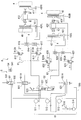
- FIG. 2 is a hydraulic circuit diagram of the construction machine according to the embodiment.
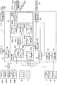
- the functional block diagram which shows the partial structure of FIG. 3 in detail.
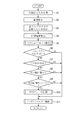
- action of the TCS controller which concerns on the said embodiment The flowchart for demonstrating the effect
- FIG. 1 shows a dump truck 1 according to an embodiment of the present invention.
- the dump truck 1 is an articulate type having independent body frames at the front and rear, and the vehicle body constituting the dump truck 1 includes an engine 1A, a transmission 1B, differential mechanisms 1C to 1F, and a differential adjustment mechanism 1CA.
- the output of the engine 1A is controlled by the engine controller 2 and transmitted to the transmission 1B.
- the transmission 1B includes a torque converter and a lockup mechanism (not shown), and the transmission controller 3 performs shift control and lockup control of the transmission 1B.
- the rotational driving force transmitted from the engine 1A to the transmission 1B is transmitted to the road surface by rotating all the wheels 4 through the differential mechanisms 1C to 1F.
- the differential mechanism 1C includes a differential adjustment mechanism 1CA, and the differential in the differential mechanism 1C can be constrained by the differential adjustment mechanism 1CA. Further, the differential mechanisms 1D, 1E, and 1F are configured to allow only the left and right wheel differentials. For this reason, the differential mechanism 1E is configured to allow only the differential between the left and right wheels, and is in a so-called direct connection state where the differential between the front and rear wheels is not allowed.
- a front brake 41 and a center brake 42 are provided on the wheel 4 portion of the vehicle body, and the front brake 41 and the center brake 42 are hydraulically connected to the brake hydraulic circuit 5 and the TCS control hydraulic circuit 6. .
- the braking mechanism of the present invention includes a front brake 41, a center brake 42, a brake hydraulic circuit 5, and a TCS control hydraulic circuit 6.
- each wheel 4 is provided with a rotation speed sensor (rotation speed detection means) 43FL, 43FR, 43CL, 43CR for detecting the rotation speed of the wheel 4.
- the rotational speed signals detected by the rotational speed sensors 43FL, 43FR, 43CL, and 43CR, and the articulate angle (refraction angle) between the front and rear body frames detected by the articulate angle sensor 7A are supplied to the TCS controller 7 as electrical signals. Is output.
- the TCS controller 7 is electrically connected to a TCS system switch 7B for canceling TCS control.
- the TCS controller 7 includes a TCS brake control for controlling the brake torque of the front brake 41 and the center brake 42 via the hydraulic circuits 5 and 6, and an interaxle differential control for adjusting the differential binding force of the differential adjustment mechanism 1CA. Both controls are performed as TCS control.
- the TCS controller 7 also serves as a retarder control controller, and performs retarder control based on an operation signal from a retarder operating lever 7C for setting a retarder speed.
- FIG. 2 shows the brake hydraulic circuit 5 of the dump truck 1.
- the front brake 41 and the center brake 42 include multi-plate brakes 411 and 421 and slack adjusters 412 and 422, respectively.
- the slack adjusters 412 and 422 are devices that automatically adjust the clearance due to wear of the rotating portions of the front brake 41 and the center brake 42.
- the slack adjusters 412 and 422 are connected to the brake hydraulic circuit 5 and the TCS control hydraulic circuit 6, respectively. Hydraulically connected.
- the front brake 41 and the center brake 42 are all controlled by oil pressure. When pressure oil is output from the brake oil pressure circuit 5, pressure oil is supplied to each part of the front brake 41 and center brake 42 via the TCS control oil pressure circuit 6. Are supplied, and each part is operated by hydraulic pressure.
- the brake hydraulic circuit 5 includes a hydraulic pressure supply system 51, a foot type brake valve 52, and a parking brake valve 53.
- the hydraulic supply system 51 includes a plurality of hydraulic accumulators 511, 512, 513, a hydraulic pump 514, and a tank 515 as hydraulic sources, and the pressure oil of these hydraulic accumulators 511, 512, 513 passes through the TCS control hydraulic circuit 6,
- the wheels 4 are braked by being sent to the front brake 41 and the center brake 42, respectively.
- the hydraulic accumulators 511, 512, and 513 boost the hydraulic oil in the tank 515 by a hydraulic pump 514 driven by the engine 1A that is a driving source, and receive the pressure oil from the hydraulic pump 514 to accumulate a predetermined pressure. When the predetermined pressure is reached, the unloading device 516 provided between the hydraulic pump 514 and the hydraulic accumulator 513 unloads the hydraulic oil from the hydraulic pump 514.
- the foot type brake valve 52 includes a front wheel brake valve 521 and a central wheel brake valve 522.
- the front wheel brake valve 521 becomes the front brake 41, and the central wheel brake valve 522
- the center brake 42 is braked by sending hydraulic oil from the hydraulic accumulators 511 and 512, respectively.
- the brake pedal 523 is operated to change the spool position of the front wheel brake valve 521, and the pressure oil in the hydraulic accumulator 511 is output from the front wheel brake valve 521.
- This pressure oil is supplied to the front brake 41 via the front wheel hydraulic circuit 61 of the TCS control hydraulic circuit 6, and braking by the front brake 41 is performed.
- the pressure oil output from the front-wheel brake valve 521 acts on the left and right front brakes 41 through the shuttle valves 614 and 615 with substantially the same pressure. For this reason, braking with the same braking force is performed on the left and right.
- the spool position of the central wheel brake valve 522 is also changed at the same time, and the pressure oil in the hydraulic accumulator 512 is output from the central wheel brake valve 522.
- This pressure oil is supplied to the center brake 42 via the central wheel hydraulic circuit 62 and is braked by the center brake 42.
- the pressure oil output from the central wheel brake valve 522 acts on the left and right center brakes 42 via the shuttle valves 624 and 625 with substantially the same pressure, so the same braking force is applied on the left and right. Braking is performed.
- the parking brake valve 53 is a valve that operates the parking brake 54 and includes a solenoid 531 and a spring portion 532.
- the parking brake valve 53 is switched in position by a solenoid 531 when a parking switch (not shown) is switched to the parking position, and pressure oil in the cylinder chamber 541 of the parking brake 54 is supplied to the hydraulic supply system 51.
- the parking brake pressure is made zero by returning to the tank 515.
- the braking state is held by the spring force of the parking brake 54.
- the parking brake valve 53 is switched in position by switching a parking switch (not shown) to the traveling position.
- a parking switch (not shown) to the traveling position.
- the pressure oil from the hydraulic accumulator 513 is supplied to the cylinder chamber 541 of the parking brake 54 to increase the parking braking pressure.
- the parking brake 54 is provided in parallel with the front brake 41 or the center brake 42, or is provided on a brake provided alongside a drive shaft that transmits driving force.
- TCS Control Hydraulic Circuit 6 As shown in FIG. 2, a TCS control hydraulic circuit 6 is provided in the middle of the hydraulic circuit from the brake hydraulic circuit 5 to the front brake 41 and the center brake 42.
- the TCS control hydraulic circuit 6 includes a front wheel hydraulic circuit 61 and a central wheel hydraulic circuit 62.
- the front wheel hydraulic circuit 61 is configured as a hydraulic circuit that performs TCS brake control of the front brake 41, and includes a front wheel TCS switching valve 611, two electromagnetic proportional control valves 612 and 613, two shuttle valves 614 and 615, and a pressure sensor. 616,617 is comprised.
- the front wheel TCS switching valve 611 switches whether or not to perform the TCS brake control on the front brake 41 side by outputting an electric signal from the TCS controller 7 to the solenoid 611A constituting the switching valve 611. it can.
- the electromagnetic proportional control valves 612 and 613 are respectively provided in piping lines branched in the middle of the piping line connected to the output side of the front wheel TCS switching valve 611, and the brake pressure of the front brake 41 is controlled during TCS brake control. It is a control valve to control.
- the electromagnetic proportional control valve 612 is a valve that controls the supply of pressure oil to the left side of the front brake 41, and the electromagnetic proportional control valve 613 controls the supply of pressure oil to the right side of the front brake 41. It is a valve.
- Each of the electromagnetic proportional control valves 612 and 613 has its opening degree adjusted by the solenoids 612A and 613A, and a part of the hydraulic oil discharged after being decompressed is returned to the tank 515 of the hydraulic pressure supply system 51 described above.
- the shuttle valves 614 and 615 are provided on the output side of the electromagnetic proportional control valves 612 and 613, and one input is connected to the output of the electromagnetic proportional control valves 612 and 613, but the other input is mutually connected.
- the shuttle valves 614 and 615 are connected by pipes that communicate with each other. In the middle of this piping, the output piping of the front wheel brake valve 521 is connected.
- the pressure sensors 616, 617 are provided in the middle of the piping between the shuttle valves 614, 615 and the electromagnetic proportional control valves 612, 613, detect the brake pressure of the front brake 41, and use the detected signal as an electrical signal for the TCS controller 7 Output to.
- the central wheel hydraulic circuit 62 is configured as a hydraulic circuit that performs TCS brake control of the center brake 42, and similarly to the front wheel hydraulic circuit 61, the central wheel TCS switching valve 621, two electromagnetic proportional control valves 622, 623. Two shuttle valves 624 and 625 and pressure sensors 626 and 627 are provided. The pressure sensors 616 and 617 may be provided in the middle of piping between the shuttle valves 614 and 615 and the front brake 41, and the pressure sensors 626 and 627 may be provided in the middle of piping between the shuttle valves 624 and 625 and the center brake 42, respectively. good.
- the central wheel TCS switching valve 621 is provided with a solenoid 621A. Similarly, the central wheel TCS switching valve 621 determines whether the TCS operation on the center brake 42 side is operable or not based on the electrical signal output from the TCS controller 7. Switch.
- the electromagnetic proportional control valves 622 and 623 are also provided with solenoids 622A and 623A, and the opening degrees of the electromagnetic proportional control valves 622 and 623 are adjusted based on the electrical signal output from the TCS controller 7. .
- Such a TCS control hydraulic circuit 6 functions as a TCS by changing the positions of the valves constituting the front wheel hydraulic circuit 61 and the central wheel hydraulic circuit 62 described above.
- FIG. 2 when the spool of the front wheel TCS switching valve 611 is in the upper position and when the spool of the central wheel TCS switching valve 621 is in the upper position, the TCS function is cut off.
- the TCS function is effective.
- the pressure oil output from the front wheel TCS switching valve 611 is supplied to the electromagnetic proportional control valves 612 and 613, and the electromagnetic proportional control is performed according to the electrical signal from the TCS controller 7.
- the opening degree of the valves 612 and 613 is adjusted, and the pressure oil output from the electromagnetic proportional control valves 612 and 613 is supplied to the front brake 41 via the shuttle valves 614 and 615.
- the pressure oil output from the central wheel TCS switching valve 621 is supplied to the electromagnetic proportional control valves 622 and 623, and the pressure output from the electromagnetic proportional control valves 622 and 623.
- the oil is supplied to the center brake 42 via shuttle valves 624 and 625.
- the TCS controller 7 monitors the rotational speed of the wheels 4 detected by the rotational speed sensors 43FL, 43FR, 43CL, and 43CR, and determines the solenoid according to the slip rate state of each wheel 4. Electric signals to 612A, 613A, 622A, and 623A are output.
- each electromagnetic proportional control valve 612, 613, 622, 623 is adjusted, and the braking force of the front brake 41 and the center brake 42 is adjusted.
- the TCS controller 7 performs control such that the driving force of each wheel 4 is adjusted to an optimum value and the course trace performance during turning is ensured.
- the pressure oil output from the front wheel brake valve 521 is supplied to the front brake 41 via the shuttle valves 614 and 615, and the brake pedal 523 is depressed. It operates as a normal brake whose braking force increases with the amount.
- the pressure oil output from the central wheel brake valve 522 is supplied to the center brake 42 via the shuttle valves 624 and 625, and similarly functions as a normal brake.
- the electromagnetic proportional control valves 612, 613, 622, and 623 are also used as control valves for retarder control. According to the retarder command signal from the TCS controller 7, the electromagnetic proportional control valves 612, 613, 622, and 623 are used. Is adjusted.
- FIGS. 3 and 4 show the configuration of the TCS controller 7 that performs the TCS control described above.
- the TCS controller 7 includes a memory 71 and a calculation processing device 72 as storage devices.
- the memory 71 stores a program for operating on the arithmetic processing unit 72, a map for controlling the TCS sliding mode, and the like, and is read in response to a request from the arithmetic processing unit 72.
- rotational speed sensors 43FL, 43FR, 43CL, 43CR, articulate angle sensor 7A, TCS system switch 7B, retarder operation lever 7C, and pressure sensors 616, 617, 626, 627 are electrically connected. It is connected to the.
- the rotation speed sensors 43FL, 43FR, 43CL, and 43CR are connected to the arithmetic processing unit 72 via an LPF (Low Pass Filter) 73, and the rotation output from the rotation speed sensors 43FL, 43FR, 43CL, and 43CR.
- the speed signal is input to the arithmetic processing unit 72 as the rotational speed ⁇ fl, ⁇ fr, ⁇ cl, ⁇ cr of each wheel 4 in a state in which high-frequency components such as disturbance are removed.
- solenoids 611A, 621A of the TCS switching valves 611, 621 and solenoids 612A, 613A of the electromagnetic proportional control valves 612, 613, 622, 623 of the TCS control hydraulic circuit 6 are provided on the output side of the arithmetic processing unit 72.
- 622A and 623A are electrically connected.
- the arithmetic processing unit 72 is electrically connected to the engine controller 2 and the transmission controller 3, and is configured to be able to exchange information between each other.
- the arithmetic processing unit 72 sends various information necessary for TCS control, such as the engine output torque value from the engine controller 2 and the gear position information and lockup information from the transmission controller 3, to the engine controller 2 and the transmission. It can be acquired from the controller 3.
- Such an arithmetic processing unit 72 includes a vehicle speed acquisition unit (vehicle speed estimation unit) 80, a control permission determination unit 81, a control start determination unit 82, a control end determination unit 83, a braking mechanism control unit 84, and a differential adjustment mechanism control unit 85. , And retarder control means 86.
- the vehicle speed acquisition means 80 is a part that acquires the vehicle speed of the construction machine.
- the vehicle speed acquisition means 80 estimates the vehicle speed V at an arbitrary time based on the rotational speeds ⁇ fl, ⁇ fr, ⁇ cl, ⁇ cr of the wheels 4 from the rotational speed sensors 43FL, 43FR, 43CL, 43CR.
- the control permission determination means 81 determines whether or not TCS control is permitted. Specifically, the control permission determination means 81 is based on the ON / OFF state of the TCS system switch 7B, the operation state of the brake pedal 523, the gear position information of the transmission 1B, the control state of retarder control, and the operation state of an accelerator pedal (not shown). Thus, it is determined whether or not the TCS control can be permitted.
- the control start determination means 82 is a part for determining whether or not the TCS control start condition is satisfied.
- the right / left wheel rotational speed ratio ⁇ ee calculated by the following equations (1) to (3), It is determined whether to start the TCS brake control and the interaxle differential control based on the difference between the rotational speeds ⁇ lr and the difference between the rotational speeds ⁇ fc of the front and rear wheels.
- the control start determination unit 82 includes a left and right wheel rotation speed ratio calculation unit 821, a left and right wheel rotation speed difference calculation unit 822, a front and rear wheel rotation speed difference calculation unit 823, a control threshold setting unit 824, and a control start determination unit 825. It has. Of these, the right and left wheel rotation speed ratio calculation unit 821 calculates the right and left wheel rotation speed ratio ⁇ ee by the following equation (1), and the left and right wheel rotation speed difference calculation unit 822 calculates the right and left wheel rotation speed by the following equation (2). Is calculated for the front wheel and the center wheel, respectively. Further, the front-rear wheel rotational speed difference calculation unit 823 calculates the front-rear wheel rotational speed difference ⁇ fc according to the following equation (3).
- the control threshold value setting unit 824 corrects a predetermined threshold value stored in advance in the memory 71 based on the articulate angle and the change amount of the articulate angle, and sets a control start threshold value. Specifically, the control threshold value setting unit 824 uses the predetermined threshold value for the left and right wheel rotational speed ratio and the predetermined threshold value for the left and right wheel rotational speed difference stored in the memory 71 as the amount of change in the articulate angle and the articulate angle. And a control start threshold value for the left and right wheel rotation speed ratio and a control start threshold value for the left and right wheel rotation speed difference are set. Further, the control threshold value setting unit 824 sets a control start threshold value for the front and rear wheel rotational speed difference according to the vehicle speed.
- the control start determination unit 825 has a threshold value set by the control threshold setting unit 824 as at least one of the calculated rotation speed ratio ⁇ ee between the left and right wheels, the rotation speed difference ⁇ lr between the left and right wheels, and the rotation speed difference ⁇ fc between the front and rear wheels. It is determined whether or not the above has been reached. Then, the control start determination unit 825 determines whether to start the TCS brake control and the interaxle differential control according to the determination result.
- the control end determination means 83 is a part for determining whether or not to end the TCS control.
- the control end determination means 83 refers to a control deviation S of each wheel 4 to be described later and determines the end of the front wheel TCS brake control, the center wheel TCS brake control, and the interaxle differential control.
- the braking mechanism control means 84 is a part that generates and outputs a TCS control command, and is an actual slip ratio calculation section 841, a target slip ratio setting section 842, a control deviation calculation section (control deviation calculation means) 843, and a traction force estimation. Unit (traction force estimation means) 844 and a braking mechanism control unit 845.
- the actual slip ratio calculation unit 841 calculates the actual slip of each wheel 4 based on the vehicle speed V obtained by the vehicle speed acquisition means 80, the radius r of the wheel 4, and the rotational speeds ⁇ fl, ⁇ fr, ⁇ cl, ⁇ cr of each wheel 4.
- the rate ⁇ is calculated by the following equation (4).
- the target slip ratio setting unit 842 calculates a target slip ratio ⁇ for each wheel 4 by the following equation (5).
- ⁇ s is a reference target slip ratio, and in this embodiment, a predetermined value stored in advance in the memory 71 is used.
- ⁇ a is a corrected target slip ratio that is added to the reference target slip ratio ⁇ s when setting the target slip ratio of the outer wheel during turning, and is set according to the articulate angle. As a result, as the articulate angle increases, the value of the corrected target slip rate ⁇ a is also set to be larger.
- the control deviation calculation unit 843 calculates the control deviation S in generating the control command, that is, the deviation between the target value related to the control amount and the actual value.
- the TCS control is performed by the sliding mode control, and the control deviation S is calculated by the following equation (6) using the slip ratio ⁇ and the target slip ratio ⁇ .
- the traction force estimation unit 844 is based on engine output torque transmitted from the engine controller 2, gear speed information transmitted from the transmission controller 3, and specification data of the dump truck 1 stored in the memory 71 in advance.
- the traction force which is the force transmitted from the wheel 4 to the road surface, is estimated. Further, the traction force estimation unit 844 corrects the traction force according to the control deviation S from the control deviation calculation unit 843 so that the TCS control is stabilized even when the estimation error of the traction force is large.
- the traction force estimation unit 844 includes a control state determination unit 844A, a traction force initial value setting unit 844B, and a traction force correction unit 844C.
- the control state determination unit 844A determines the control state of the TCS control based on the determination result of the control start determination means 82.
- the traction force initial value setting unit 844B sets the initial value of the traction force according to the determination result of the control state determination unit 844A. In setting the initial value, the traction force initial value setting unit 844B acquires the input driving force Fin1 of the wheel 4 obtained by the following equation (7) when neither the TCS brake control nor the interaxle differential control is performed. Further, when the TCS brake control is performed only on the front wheel 4 or the center wheel 4, the traction force initial value setting unit 844B is obtained by the following equation (8) with respect to the one where the TCS brake control is not performed. The input driving force Fin2 is continuously acquired. Then, the traction force initial value setting unit 844B initializes the traction force using the input driving force Fin1 or the input driving force Fin2.
- Ts is the output torque from the differential mechanism 1D of the front wheel 4 or the differential mechanism 1E of the central wheel 4
- the output torque Ts is the differential stored in the memory 71 in advance. It is calculated based on the specification data of the dump truck 1 such as the reduction ratios of the mechanisms 1C to 1F, the output torque of the engine transmitted from the engine controller 2, and the shift speed information transmitted from the transmission controller 3.
- the traction force correction unit 844C corrects the traction force based on the control deviation S of the TCS control.
- the traction force correcting unit 844C of the present embodiment sets the traction force initial value based on the control deviation S calculated by the control deviation calculating unit 843. If the traction force is initialized by the unit 844B, the traction force is corrected based on the initial value, otherwise, based on the traction force of the previous calculation cycle.
- the braking mechanism control unit 845 generates and outputs a control command for TCS brake control.
- the braking mechanism control means 84 generates and outputs a control command to the TCS control hydraulic circuit 6 by applying a sliding mode control control law to the vehicle model of the dump truck 1.
- the braking mechanism control unit 845 includes a target brake torque calculation unit 845A, a target brake torque determination unit 845B, a reference wheel determination unit 845C, a target brake torque reduction unit 845D, and a control command generation unit 845E.
- the target brake torque calculation unit 845A calculates the target brake torque of each wheel 4 in the TCS brake control based on the vehicle model of the dump truck 1.
- the vehicle model of the dump truck 1 uses the inertia J of the wheel, the rotational speed ⁇ of the wheel, the torque Tin output from the differential mechanisms 1C and 1E and input to the wheel, the traction force F, and the brake torque Tb as follows. It is expressed by equation (9).
- K is a control gain of the sliding mode control, and is set to have a characteristic as shown in FIG. 5, for example.
- Tb Tin / 2 ⁇ r ⁇ F ⁇ (dV / dt) / ⁇ + (K / ⁇ ) ⁇ S (12)
- Tin r ⁇ (Fr + Fl) + (Tbl + Tbr) + J ⁇ ((d ⁇ l / dt) + (d ⁇ r / dt)) (13)
- Tbl Tin / 2 ⁇ r ⁇ Fl ⁇ (dV / dt) / ⁇ + (K / ⁇ ) ⁇ S (14)
- Tbr Tin / 2 ⁇ r ⁇ Fr ⁇ (dV / dt) / ⁇ + (K / ⁇ ) ⁇ S (15)
- the target brake torque calculation unit 845A calculates the target brake torque of each wheel 4 using Expression (16) and Expression (17).
- Tbl J ⁇ (d ⁇ l / dt + d ⁇ r / dt) / 2 + r ⁇ (Fr-Fl) / 2 + (Tbl + Tbr) / 2- (dV / dt) / ⁇ + (K / ⁇ ) ⁇ S (16)
- Tbr J ⁇ (d ⁇ l / dt + d ⁇ r / dt) / 2 + r ⁇ (F1 ⁇ Fr) / 2 + (Tbl + Tbr) / 2 ⁇ (dV / dt) / ⁇ + (K / ⁇ ) ⁇ S (17)
- the brake torque Tb is proportional to the brake pressure P, and the relationship of the following formula (18) is established between the brake torque Tb and the brake pressure P (k: brake torque conversion coefficient).
- the brake pressure P is a value uniquely determined with respect to the brake torque Tb, and the brake torque Tb and the brake pressure P are in an equivalent relationship as parameters for adjusting the brake amount.
- the target brake torque calculation part 845A of this embodiment has each converted the target brake torque of each wheel 4 into the target brake pressure using Formula (18).
- the target brake torque determination unit 845B determines whether or not the target brake torque of each wheel 4 is equal to or greater than a threshold value stored in advance in the memory 71. That is, the target brake torque determination unit 845B determines whether or not the target brake torques of both front wheels 4 and both center wheels 4 are equal to or greater than the front wheel threshold and the rear wheel threshold, respectively.
- the target brake torque determination unit 845B of the present embodiment performs the determination using the target brake pressure. Accordingly, the front wheel and rear wheel pressure thresholds with respect to the target brake pressure, and the front wheel and rear wheel brake torque conversion coefficients are stored in the memory 71 in advance. That is, the threshold value for the target brake torque is stored in advance as a pressure threshold value and a brake torque conversion coefficient, and a value obtained by multiplying the pressure threshold value by the brake torque conversion coefficient is the threshold value for the target brake torque.
- the reference wheel determination unit 845C determines a reference wheel for TCS brake control based on the target brake torque of each wheel 4. As described above, since the target brake pressure corresponds to the target brake torque, the reference wheel determination unit 845C of the present embodiment determines the reference wheel using the target brake pressure.
- the target brake torque reduction unit 845D reduces the target brake torque of each wheel 4 according to the difference between the target brake torque of the reference wheel and the threshold when the target brake torque of each wheel 4 is equal to or greater than the threshold.
- the target brake torque reduction unit 845D uses the target brake pressure in the process, as in the case of the target brake torque determination unit 845B and the reference wheel determination unit 845C.
- the control command generation unit 845E generates a control command for each of the electromagnetic proportional control valves 612, 613, 622, and 623 so that the braking state of the wheel 4 becomes the brake pressure P corresponding to the target brake torque.
- a control signal is output to the solenoids 612A, 613A, 622A, and 623A constituting the electromagnetic proportional control valves 612, 613, 622, and 623. Thereby, the opening degree of the electromagnetic proportional control valves 612, 613, 622, 623 is adjusted, and the braking force of each wheel 4 is controlled.
- the differential adjustment mechanism control means 85 generates a control command for controlling the differential binding force of the differential mechanism 1C, and outputs the generated control command to the differential adjustment mechanism 1CA. That is, the differential adjustment mechanism control means 85 generates a control command for restricting the differential of the differential mechanism 1C when the control start determination means 82 determines that the interaxle differential control is to be performed. Output to 1CA.
- the retarder control means 86 performs retarder control based on the operation signal from the retarder operating lever 7C. That is, the retarder control means 86 generates and outputs control signals to the solenoids 612A, 613A, 622A, and 623A described above based on the operation signal from the retarder operation lever 7C.
- the TCS controller 7 includes the rotational speeds ⁇ fl, ⁇ fr, ⁇ cl, ⁇ cr output from the rotational speed sensors 43FL, 43FR, 43CL, 43CR, the articulate angle output from the articulate angle sensor 7A, the engine Various input signals such as engine torque information from the controller 2, gear speed information from the transmission controller 3, and a lockup operation signal are acquired (step S1).
- the vehicle speed acquisition means 80 estimates the vehicle speed V at an arbitrary time based on the rotational speeds ⁇ fl, ⁇ fr, ⁇ cl, and ⁇ cr of the wheels 4 (processing S2).
- the actual slip ratio calculation unit 841 determines the vehicle speed V obtained by the vehicle speed acquisition means 80, the radius r of the wheels 4, and the rotational speeds ⁇ fl, ⁇ fr, ⁇ cl, and ⁇ cr of each wheel 4. Based on this, the actual slip ratio ⁇ for each wheel 4 is calculated.
- the target slip ratio setting unit 842 also sets the target slip ratio ⁇ for each wheel 4 based on the reference target slip ratio ⁇ s stored in the memory 71 and the corrected target slip ratio ⁇ a set according to the articulate angle. Is calculated (step S3).
- the control deviation calculation unit 843 calculates the control deviation S for each wheel 4 from the slip ratio ⁇ and the target slip ratio ⁇ (processing S4).
- the traction force estimation unit 844 determines whether the front wheel 4 and the central wheel are based on the engine output torque transmitted from the engine controller 2, the gear speed information transmitted from the transmission controller 3, and the specification data of the dump truck 1. 4 traction forces are estimated (step S5). Note that the estimation of the traction force F does not necessarily have to be performed at this stage as long as it is performed before the processing S10 described later.
- the control permission determination unit 81 When determining whether or not the TCS control can be permitted, the control permission determination unit 81 first confirms the on / off state of the TCS system switch 7B (processing S6). When the TCS system switch 7B is in the TCS control cancel state, the control permission determination unit 81 does not permit TCS control. In this case, since the TCS control is not performed, the driving force transmitted from the engine 1A via the transmission 1B and the differential mechanisms 1C to 1F is transmitted to the wheels 4 as it is.
- the control permission determination means 81 determines the retarder control command value, the brake pedal on / off status, the gear position of the transmission 1B, and the accelerator. Based on the on / off state of the pedal, it is determined whether or not the TCS control is permitted (step S7). Specifically, the control permission determination unit 81 determines whether or not the TCS control is permitted based on the following Table 1. If it is determined in step S7 that the TCS cannot be permitted, the TCS control is not performed. If it is determined that the TCS can be permitted, the process proceeds to the next process.
- the control start determination unit 825 is calculated by the left and right wheel rotation speed ratio calculation unit 821, the left and right wheel rotation speed difference calculation unit 822, and the left and right wheel rotation speed difference calculation unit 823, respectively. It is determined whether at least one of the wheel rotation speed ratio ⁇ ee, the left and right wheel rotation speed difference ⁇ lr, and the front and rear wheel rotation speed difference ⁇ fc has exceeded the respective threshold values calculated by the control threshold value setting unit 824. That is, the control start determination means 82 determines whether or not it is necessary to start the TCS brake control and the interaxle differential control based on the following Table 2 (processing S8).
- the predetermined threshold value for the left and right wheel rotational speed ratio and the predetermined threshold value for the left and right wheel rotational speed difference are represented by changes in the articulate angle and the articulate angle. Correct and set according to the amount. In this way, by increasing the control start threshold during turning, the early operation of TCS control due to the inner / outer wheel speed difference is prevented.
- the threshold value d for the front and rear wheel rotational speed difference of the patterns D1 and D2 is set smaller than the threshold value e for the front and rear wheel rotational speed difference of the pattern E. Further, the threshold value dm for the transmission output speed of the patterns D1 and D2 is set smaller than the threshold em for the transmission output speed of the pattern E.
- the control start determination unit 82 sets a TCS control start timer when at least one of the rotation speed ratio ⁇ ee of the left and right wheels, the rotation speed difference ⁇ lr of the left and right wheels, and the rotation speed difference ⁇ fc of the front and rear wheels exceeds the respective thresholds. Counting up, and when the counter exceeds a predetermined value, at least one of TCS brake control and interaxle differential control is started according to a previously stored control pattern table.
- the control start determination means 82 sets each control flag when the TCS brake control or the inter-axle differential control is necessary, and resets each control flag when it is not necessary.
- the TCS brake control flag is provided separately between the front wheel 4 and the central wheel 4 and is set or reset independently as the front wheel TCS brake control flag and the central wheel TCS brake control flag.
- the control end determination means 83 refers to the control deviation S of each wheel 4 and determines whether or not the TCS control should be ended. That is, when the control deviation S falls below the control end threshold, the control end determination unit 83 instructs the braking mechanism control unit 84 to end the TCS brake control by resetting the TCS brake control flag. Further, the control end determination means 83 resets the interaxle differential control flag and instructs the differential adjustment mechanism control means 85 to end the interaxle differential control (process S9).
- the braking mechanism control means 84 is configured so that each electromagnetic proportional control valve 612 is based on the target brake torque calculated by the above formulas (16) and (17). , 613, 622, 623 for the solenoids 612A, 613A, 622A, 623A are generated and output (processing S10). Thereby, the opening degree of the electromagnetic proportional control valves 612, 613, 622, 623 is adjusted, and the braking force of each wheel 4 is controlled.
- the braking mechanism control unit 84 when the TCS brake control is not performed, the braking mechanism control unit 84 outputs a signal such that the current value becomes zero to the solenoids 612A, 613A, 622A, and 623A.
- the braking mechanism control means 84 immediately after the state of the TCS brake control flag is switched from set to reset, the braking mechanism control means 84 sends a control command for gradually reducing the brake torque by the TCS brake control to the solenoids 612A, 613A, 622A, To 623A. That is, the braking mechanism control means 84 issues a command to gradually decrease the current values of the solenoids 612A, 613A, 622A, and 623A from the value when the TCS brake control flag is reset to zero.
- finish of control is prevented, and it is preventing that TCS control is intermittently performed with a short period.
- the differential adjustment mechanism control means 85 performs the interaxle differential control based on the determination results of the control start determination means 82 and the control end determination means 83 (process S11). Specifically, the differential adjustment mechanism control means 85 generates a control command (command amount 100%) that maximizes the differential binding force of the differential mechanism 1C when the interaxle differential control flag is set. Then, the control command is output to the differential adjustment mechanism 1CA. On the other hand, when the interaxle differential control flag is not set, the differential adjustment mechanism control means 85 outputs a control command (command amount 0%) for setting the differential binding force of the differential mechanism 1C to zero as the differential adjustment mechanism 1CA. Output to.
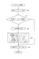
- the control state determination unit 844A determines the control state of TCS brake control. That is, the control state determination unit 844A determines whether the front wheel TCS brake control flag is set, whether the center wheel TCS brake control flag is set, and whether the TCS control start timer has started counting. Determination is made (processing S72).
- step S72 If it is determined in step S72 that neither the front wheel 4 nor the central wheel 4 has the TCS brake control flag set, and the TCS control start timer has not started counting, the control state determination unit 844A further controls the interaxle. It is determined whether or not the differential control flag is set (step S73). When the inter-axle differential control flag is not set, the traction force initial value setting unit 844B acquires the input driving force Fin1 of the front wheel 4 and the central wheel 4 according to the equation (7) (processing S74).
- the traction force estimation unit 844 determines that the front wheel 4 The initial value of the traction force F is set (step S75), and the initial value of the traction force F of the central wheel 4 is set (step S76).
- the control state determination unit 844A determines whether or not the front wheel TCS brake control flag is set (step S751).
- the traction force initial value setting unit 844B acquires the input driving force Fin2 of the front wheel 4 using Expression (8) (process S752).
- the control state determination unit 844A further determines whether or not the TCS brake control of the front wheel 4 has switched from the non-control state to the control state. Determination is made (processing S753).
- the traction force initial value setting unit 844B performs this input driving if the input driving force Fin2 of the wheel 4 is calculated.
- the traction force F of the wheel 4 is initialized with the force Fin2, otherwise with the input driving force Fin1 (step S754).
- the setting of the initial value of the traction force F of the central wheel 4 is the same as that of the front wheel 4 as shown in S761 to S764 in FIG.
- the traction force correcting unit 844C determines whether the front wheel 4 and the front wheel 4 and The traction force F of the central wheel 4 is corrected (processing S77). Specifically, as shown in FIG. 9, the traction force correcting unit 844C corrects the traction force F when the control deviation S is within a range of predetermined values D1 to U1 including zero in the range. , Keep the value as it is.
- the traction force correcting unit 844C decreases the traction force F by the predetermined value Kd every calculation cycle, and the control deviation S is reduced.
- the traction force F is increased by a predetermined value Kd when it is within a range of predetermined values U1 to U2 smaller than U1. Thereby, the traction force F is gradually corrected so as to reduce the absolute value of the control deviation S, that is, to converge the TCS control.
- the traction force correction unit 844C multiplies the traction force F by the coefficient Gd every elapse of a predetermined interval time longer than the calculation cycle, and the control deviation S is a predetermined value. If it falls below U2, the traction force F is multiplied by the coefficient Gu every time the interval time elapses. As a result, the traction force F is corrected more rapidly than when the absolute value of the control deviation S is equal to or less than the predetermined value D2 or U2.
- the control deviation S being zero corresponds to 35% in terms of slip rate.
- the actual slip ratio ⁇ exceeds 45%
- the driving force that can be transmitted to the road surface and the side force of the wheels start to decrease, and when it exceeds 55%, both of them significantly decrease to improve acceleration performance and course tracing performance. Reduce.
- the slip ratio ⁇ is less than 25%
- the driving force transmitted to the road surface starts to decrease
- the slip ratio ⁇ is less than 15%
- the driving force corresponding to the friction coefficient of the road surface is not obtained. It will cause defects.
- U2, U1, D1, and D2 are set to 15%, 25%, 45%, and 55%, respectively, in terms of slip ratio, and the traction force correction speed is the value of the control deviation S.
- the target brake torque calculation unit 845A calculates the target brake torque of each wheel 4 by the above-described formula (16) and formula (17) (processing S20). Further, the target brake torque calculation unit 845A converts the target brake torque of each wheel 4 into the target brake pressure using the equation (18).
- the target brake torque determination unit 845B determines whether or not the target brake torque of each wheel 4 is equal to or greater than a threshold value.
- the brake torque and the brake pressure P are in an equivalent relationship as parameters for adjusting the brake amount. Therefore, in the present embodiment, the target brake torque determination unit 845B determines that the target brake pressure for both front wheels 4 is equal to or greater than the pressure threshold for the front wheels, and the target brake pressure for both center wheels 4 is equal to or greater than the pressure threshold for the center wheels. It is determined whether or not (process S21).
- reference wheel determination unit 845C determines the reference wheel.
- the reference wheel determination unit 845C determines that the wheel having the smallest target brake pressure among the wheels 4 is the reference wheel (processing S22). For example, in FIG. 11 showing the target brake pressure of the front wheel 4 and the center wheel 4, the reference wheel determination unit 845C recognizes that the target brake pressure Pf of the front wheel 4 is smaller than the target brake pressure Pc of the center wheel 4.
- the front wheel 4 is determined as a reference wheel.
- the target brake torque reduction unit 845D reduces the target brake torque of each wheel 4 according to the difference between the target brake torque of the reference wheel and the threshold value (processing S23).
- the target brake torque reduction unit 845D of the present embodiment calculates a differential pressure ⁇ Pf between the target brake pressure Pf of one front wheel 4 that is the reference wheel and the pressure threshold value Pth. Then, the target brake torque reduction unit 845D converts the differential pressure ⁇ Pf into the brake torque using Expression (18), and calculates a value corresponding to the difference between the target brake torque of the reference wheel and its threshold value.
- the differential pressure ⁇ Pf is converted into the brake torque using a torque cut gain that is a parameter for adjusting the gain. That is, the target brake torque reduction unit 845D multiplies the value of the torque cut gain stored in the memory 71 by the differential pressure ⁇ Pf to convert it into a torque reduction amount ⁇ Tf, and subtracts the torque reduction amount ⁇ Tf from the target brake torque of the reference wheel. .
- the target brake torque reduction unit 845D also reduces the same torque reduction amount ⁇ Tf as the reference wheel from the target brake torque for the other front wheel 4 that is not the reference wheel.
- the torque reduction amount ⁇ Tf of the reference wheel is reduced from the target brake torque. That is, as shown in FIG. 11, the target brake torque of the central wheel 4 is reduced by the brake pressure ⁇ Pc obtained by dividing the torque reduction amount ⁇ Tf by the brake torque conversion coefficient k of the central wheel. .
- the target brake pressure Pc of the central wheel 4 that is the reference wheel and its pressure are the same as when the front wheel 4 becomes the reference wheel.
- the pressure difference from the threshold value is converted into a brake torque, and a torque reduction amount ⁇ Tc obtained by multiplying the converted brake torque by the value of the torque cut gain is subtracted from the target brake torque of each wheel 4.
- the target brake torque calculation unit 845A calculates the target brake torque.
- the brake torque is directly passed to the control command generator 845E.
- the control command generation unit 845E generates and outputs a control command to the electromagnetic proportional control valves 612, 613, 622, and 623 based on the target brake torque of each wheel 4 (processing S24). Thereby, the opening degree of the electromagnetic proportional control valves 612, 613, 622, 623 is adjusted, and the braking force of each wheel 4 is controlled.
- the control command generation unit 845E outputs a signal such that the current value becomes zero to the solenoids 612A, 613A, 622A, and 623A.
- the differential adjustment mechanism control means 85 recognizes whether or not the interaxle differential control is necessary (processing S30). Specifically, the differential adjustment mechanism control means 85 recognizes that the interaxle differential control is necessary when the interaxle differential control flag is on or the TCS brake control command is not zero for any wheel. Otherwise, it recognizes that interaxle differential control is not required. When recognizing that the interaxle differential control is necessary, the differential adjustment mechanism control means 85 generates a control command (command amount 100%) that maximizes the differential binding force of the differential mechanism 1C. Output to the differential adjustment mechanism 1CA (processing S31). Further, the differential adjustment mechanism control means 85 resets the interaxle differential control end counter (processing S32).
- the differential adjustment mechanism control means 85 counts up the interaxle differential control end counter (step S33), and then the counter has passed a predetermined time. It is determined whether or not it has been performed (step S34).
- a control command (command amount 100%) that maximizes the differential binding force of the differential mechanism 1C. Is output to the differential adjustment mechanism 1CA (step S31). Otherwise, a control command (command amount 0%) for setting the differential binding force of the differential mechanism 1C to zero is output to the differential adjustment mechanism 1CA ( Process S35).
- the control start determination unit 82 performs TCS control while monitoring the rotational speed ratio ⁇ ee of the left and right wheels, the rotational speed difference ⁇ lr of the left and right wheels, and the rotational speed difference ⁇ fc of the front and rear wheels. Since it is determined whether or not to implement, it is possible to selectively set whether or not the TCS brake control is necessary, the target wheel, and whether or not the interaxle differential control is necessary according to the slip state of the wheel. For this reason, since the driving force to the wheels 4 can be appropriately distributed according to the situation, the output of the engine 1A can be effectively transmitted to the road surface without being wasted due to slipping of the wheels 4. .
- control start threshold and the target slip ratio that is the control target value are calculated separately, the control start timing can be changed without affecting the control command value during TCS control. For this reason, it is possible to make a setting to increase acceleration by increasing the brake amount while preventing early operation of the TCS.
- each target brake torque is reduced when the target brake torque of each wheel 4 is equal to or greater than a threshold value stored in advance.
- the traction control device reduces the target brake torque by the same amount for each wheel 4. In this case, since the balance of the drive torque between the wheels 4 does not change before and after the reduction of the target brake torque, the drive torque of any of the wheels 4 does not protrude and become large or small. Therefore, it is possible to prevent a decrease in acceleration while ensuring running stability and course traceability.
- the brake torque for the TCS control is set in consideration of the traction force F corresponding to the frictional force between the wheel and the road surface. Adjusted to the correct value.
- the traction force F is corrected based on the control deviation S of each wheel. Therefore, when the differential torque is applied to the differential adjustment mechanism and the differential between the wheels is restricted, or when the road condition changes, the wheel is changed. Even when the frictional force 4 is changed, the traction force F is maintained at an appropriate value. Therefore, it is possible to ensure sufficient acceleration performance and course tracing performance during cornering regardless of the type of drive system and the road surface condition.
- the traction control device determines whether or not the TCS control start timer starts counting in addition to the determination of the set state of the TCS brake control flag in the control state determination unit 844A that determines the control state of the TCS control.
- the TCS control start timer starts counting when the rotational speed relationship of the wheels 4 satisfies the TCS start condition, and the TCS brake control flag is set when the count of the TCS control start timer exceeds a predetermined value. The That is, the TCS control start timer starts counting when a slip occurs, and the TCS brake control flag is set after a certain filter time has elapsed after the occurrence of slip.
- the traction force F can be initialized with a more accurate value at the time of occurrence of the slip, the estimation accuracy of the traction force F can be increased.
- the present invention is not limited to the above-described embodiments, and modifications, improvements, and the like within the scope that can achieve the object of the present invention are included in the present invention.
- the target brake torque of each wheel 4 is converted into the target brake pressure, and using this target brake pressure, it is determined whether each target brake torque is equal to or greater than a threshold, determination of the reference wheel,
- Each target brake torque is reduced, but the present invention is not limited to this.
- these processes may be performed using the target brake torque itself.
- torque threshold values for front wheels and central wheels are stored in advance in the memory 71, and the target brake torque determination unit 845B determines whether or not the target brake torque of each wheel 4 is equal to or greater than the torque threshold value. You may make it do. Further, the reference wheel determination unit 845C may determine that the wheel 4 having the smallest target brake torque is the reference wheel. Further, the target brake torque reduction unit 845D determines the target brake torque of each wheel 4 according to the difference between the target brake torque of the reference wheel and the torque threshold when the target brake torque of each wheel 4 exceeds the torque threshold. May be reduced.
- the determination as to whether or not each target brake torque is equal to or greater than the threshold, the determination of the reference wheel, and the reduction of each target brake torque are performed using the target brake pressure. These processes may be performed using the measured brake pressure of each wheel 4 acquired by the pressure sensors 616, 617, 626, 627.
- the torque cut gain is individually stored between the front wheel 4 and the center wheel 4, the torque cut gain for the front wheel for the front wheel 4, and the torque for the rear wheel for the rear wheel 4.
- the cut gain is used for each, it is not limited to this.
- the same torque cut gain value may be stored in advance for all the wheels, and this torque cut gain may be used in common for the front wheels 4 and the center wheel 4 to calculate the target brake torque reduction amount.
- different torque cut gains may be used for the left and right front wheels, the left and right rear wheels, or the wheels 4.
- the TCS brake control is performed on the front wheel 4 and the center wheel 4 among the six drive wheels of the dump truck 1, but the present invention is not limited to this. That is, it is only necessary to relatively control the front and rear wheels 4. For example, the front wheel 4 and the rear wheel 4 of the dump truck 1 are controlled, or the front wheel 4, the center wheel 4, and the rear wheel 4 are controlled. You may do it.
- the estimated vehicle speed based on the rotational speeds ⁇ fl, ⁇ fr, ⁇ cl, and ⁇ cr of the wheels 4 is acquired.
- the present invention is not limited to this, and for example, the vehicle speed is acquired from the ground speed sensor, V may be calculated.
- TCS brake control and interaxle differential control are performed as TCS control, but only TCS brake control may be performed.
- engine output control may be performed.
- the slip amount of the wheel 4 can be reduced by reducing the engine output when the engine output is too high in the first place with respect to the road surface condition. For this reason, smoother control can be realized, and the brake load during TCS brake control can be reduced.
- the traction force correction unit 844C corrects the traction force F based on the value of the previous calculation cycle according to the magnitude of the control deviation S.
- the present invention is not limited to this.
- the input driving force Fin1 and Fin2 obtained by the equation (8) are obtained every calculation cycle by the traction force initial value setting unit 844B, and the input driving force Fin1 or the input driving force is always obtained by the traction force correcting unit 844C.
- the traction force F may be corrected according to the control deviation S based on Fin2. Examples of such correction of the traction force F include those according to the following equations (19) and (20) (G1 and G2 are coefficients).
- the control state determination unit 844A of the traction force estimation unit 844 determines whether the front wheel TCS brake control flag and the center wheel TCS brake control flag are set, and the TCS control start timer counts from the count state.
- the control state of TCS control was determined, it is not restricted to this.
- the control state determination unit 844A In addition to the TCS brake control flag and the TCS control start timer, the brake torque reduction state at the end of control can be added to the determination of the control state at. As a result, it is possible to eliminate the influence of the brake torque that continues to act after the determination of the end of the TCS control, so that the traction force F can be estimated more accurately.
- the differential adjustment mechanism control means 85 controls the differential binding force between the front and rear wheels via the differential adjustment mechanism 1CA.
- a differential adjustment mechanism may be provided in the differential mechanisms 1D and 1E, and the differential adjustment mechanism control means 85 may control the operation restraining force between the left and right wheels. Even in this case, the effects of the present invention described above can be achieved.
- the differential binding force of the differential mechanism 1C is set to the maximum (command amount 100%) or zero (command amount 0%) based on the determination result of the control start determination means 82.
- the differential binding force may be linearly changed according to the control deviation S.
- the present invention is applied to the articulated dump truck 1.
- the present invention is not limited to this.
- the present invention may be applied to a wheel steering type dump truck and other construction machines.
- the control start threshold value and the target slip ratio cannot be set in consideration of the articulate angle, but the difference between the inner and outer ring speeds is smaller in the wheel steering type than in the articulated type. Is common. For this reason, by setting the control start threshold stored in advance to be slightly higher, it is possible to absorb the influence on the control start timing of the TCS.
- the present invention can be used not only for a construction machine provided with a braking mechanism provided on a wheel and a differential adjustment mechanism between front and rear driving wheels, but also for a work machine having a similar configuration.
- Control start determination unit 841 ... Actual slip ratio calculation unit, 843 ... Control deviation calculation unit (control deviation calculation means), 844 ... Traction force estimation unit (traction force estimation means), 844A ... control state determination unit, 844B ... traction force initial value setting unit, 844C ... traction force correction unit, 845 ... braking mechanism control unit, 845A ... target brake torque calculation unit, 845B ... target brake torque determination unit, 845C ... reference wheel determination unit, 845D ... target brake torque reduction unit.
Landscapes
- Engineering & Computer Science (AREA)
- Transportation (AREA)
- Mechanical Engineering (AREA)
- Chemical & Material Sciences (AREA)
- Combustion & Propulsion (AREA)
- Physics & Mathematics (AREA)
- Fluid Mechanics (AREA)
- Automation & Control Theory (AREA)
- Regulating Braking Force (AREA)
- Arrangement And Driving Of Transmission Devices (AREA)
Abstract
Description
このような建設機械における車輪の駆動力を制御するものとして、各車輪のブレーキトルクを調整するトラクションコントロール(以下、TCSと称する)装置や(例えば、特許文献1参照)、差動機構における左右の駆動輪間の差動や前後輪間の差動をロックするデフロック制御装置が知られている(例えば、特許文献2参照)。
また、特許文献2では、インタアクスルデフ制御により前輪および後輪を直結するのみであり、例えば、前後輪ともに右側または左側の車輪が同時にスリップした場合には、スリップを抑制するすべがない。従って、やはり十分な加速性を確保できない状況が発生してしまう可能性がある。
また、左右輪の回転速度差とは、建設機械の前後方向に略直交する方向に対向する車輪間の回転速度差をいい、前後輪の回転速度差とは、建設機械の前後方向に沿って設けられた車輪間の回転速度差をいう。そして、本願においては左右輪の回転速度差および前後輪の回転速度差には、建設機械の前後方向に対して対角位置上にある車輪間の回転速度差は考慮しない。
また、検出された各車輪の回転速度に基づいて、制動機構及び差動調整機構の制御を行うか否かが判定されるため、制動機構及び差動調整機構の制御要否を、共通の指標を用いて一元的に判断することができる。このため、制動機構の制御と差動調整機構の制御との間の調整を図ることが可能となり、各車輪の駆動力を適切に分配することができる。
ωee=|(ωl-ωr)/(ωl+ωr)| …(1)
ωee:回転速度比
ωl:左車輪回転速度
ωr:右車輪回転速度
ここで、制動機構の制御終了と同時に差動調整機構の制御を終了させると、各車輪間の差動拘束力が唐突になくなるため、他の車輪と比較して路面との摩擦係数が異なる車輪が、制動機構の制御終了後直ぐに突然大きなスリップを開始することがある。このような現象の発生は、急激な加速性の低下をもたらしたり、オペレータに違和感を与えたりする。
本発明によれば、制動機構の制御終了後も所定時間は差動調整機構の制御を継続するため、制動機構制の御終了直後に再度スリップが発生することを抑制できる。従って、加速性の低下を抑制でき、オペレータに違和感を与えることを防止できる。
〔1〕ダンプトラック1の構成
図1には、本発明の実施形態に係るダンプトラック1が示されている。ダンプトラック1は、前後に独立した車体フレームを有するアーティキュレート式であり、ダンプトラック1を構成する車両本体は、エンジン1A、変速機1B、差動機構1C~1F、および差動調整機構1CAを備えている。エンジン1Aの出力は、エンジンコントローラ2により制御され、変速機1Bに伝達される。変速機1Bは、図示しないトルクコンバータおよびロックアップ機構を備えて構成され、変速機コントローラ3により、変速機1Bの変速制御やロックアップ制御が行われる。
そして、エンジン1Aから変速機1Bに伝えられた回転駆動力は、差動機構1C~1Fを経て全車輪4を回転させ、路面に伝達される。
図2には、ダンプトラック1のブレーキ油圧回路5が示されている。ここで、フロントブレーキ41およびセンターブレーキ42は、多板ブレーキ411,421およびスラックアジャスタ412,422を備えて構成されている。スラックアジャスタ412,422は、フロントブレーキ41およびセンターブレーキ42の回転部分の磨耗による隙間を自動的に調整する装置であり、スラックアジャスタ412,422は、ブレーキ油圧回路5およびTCS制御用油圧回路6に油圧接続されている。
フロントブレーキ41及びセンターブレーキ42は、全て油圧によって制御され、ブレーキ油圧回路5から圧油が出力されると、TCS制御用油圧回路6を介してフロントブレーキ41及びセンターブレーキ42の各部位に圧油が供給され、各部位は油圧によって動作する。
油圧供給系51は、油圧源として複数の油圧アキュムレータ511,512,513、油圧ポンプ514、及びタンク515を備え、これら油圧アキュムレータ511,512,513の圧油がTCS制御用油圧回路6を経て、フロントブレーキ41およびセンターブレーキ42に送られてそれぞれ車輪4を制動している。
油圧アキュムレータ511,512,513は、駆動源となるエンジン1Aによって駆動される油圧ポンプ514でタンク515内の作動油を昇圧し、この油圧ポンプ514の圧油を受けて所定の圧力を蓄圧する。そして、所定の圧力に到達すると、油圧ポンプ514及び油圧アキュムレータ513の間に設けられるアンロード装置516で油圧ポンプ514の圧油をアンロードする。
図2に示されるように、ブレーキ油圧回路5からフロントブレーキ41及びセンターブレーキ42に至る油圧回路途中には、TCS制御用油圧回路6が設けられており、このTCS制御用油圧回路6は、前輪用油圧回路61及び中央輪用油圧回路62を備えて構成される。
前輪用TCS切替弁611は、当該切替弁611を構成するソレノイド611Aに、TCSコントローラ7からの電気信号を出力することにより、フロントブレーキ41側のTCSブレーキ制御を実施するか否かを切り替えることができる。
各電磁式比例制御弁612,613は、ソレノイド612A,613Aによって開度調整され、減圧されて排出された作動油の一部は、前述した油圧供給系51のタンク515に戻される。
圧力センサ616,617は、シャトル弁614,615および電磁式比例制御弁612,613間の配管途中に設けられ、フロントブレーキ41のブレーキ圧を検出し、検出された信号を電気信号としてTCSコントローラ7に出力する。
中央輪用TCS切替弁621には、ソレノイド621Aが設けられ、中央輪用TCS切替弁621は、同様にTCSコントローラ7から出力された電気信号に基づいて、センターブレーキ42側のTCSの動作可否を切り替える。
図2において、前輪用TCS切替弁611のスプールが上側のポジションにある場合、及び、中央輪用TCS切替弁621のスプールが上側のポジションにある場合には、TCS機能は遮断されている。
この場合、前輪用油圧回路61では、前輪用TCS切替弁611から出力された圧油は、電磁式比例制御弁612,613に供給され、TCSコントローラ7からの電気信号に応じて電磁式比例制御弁612,613の開度が調整され、電磁式比例制御弁612,613から出力された圧油は、シャトル弁614,615を経由してフロントブレーキ41に供給される。
この際、詳しくは後述するが、TCSコントローラ7では、回転速度センサ43FL,43FR,43CL,43CRで検出される車輪4の回転速度を監視し、各車輪4のスリップ率の状態に応じて、ソレノイド612A,613A,622A,623Aへの電気信号を出力する。これにより、各電磁式比例制御弁612,613,622,623の開度を調整し、フロントブレーキ41及びセンターブレーキ42の制動力を調整する。このように、TCSコントローラ7は、各車輪4の駆動力を最適な値に調整し、かつ旋回走行時のコーストレース性も確保できるような制御を実行する。
そして、電磁式比例制御弁612,613,622,623は、リターダ制御用の制御弁としても用いられ、TCSコントローラ7からのリターダ指令信号に従って、各電磁式比例制御弁612,613,622,623の開度が調整される。
図3および図4には、前述したTCS制御を行うTCSコントローラ7の構成が示されている。
TCSコントローラ7は、記憶装置としてのメモリ71および演算処理装置72を備えている。
メモリ71には、演算処理装置72上で動作するプログラムの他、TCSスライディングモード制御用のマップ等が格納され、演算処理装置72からの要求に応じて読み出されるようになっている。
また、演算処理装置72は、エンジンコントローラ2および変速機コントローラ3と電気的に接続されており、それぞれが互いの間で情報を交換することができるように構成されている。これにより、演算処理装置72は、エンジンコントローラ2からのエンジンの出力トルク値や、変速機コントローラ3からの変速段情報およびロックアップ情報など、TCS制御に必要な各種情報をエンジンコントローラ2および変速機コントローラ3から取得することができる。
車速取得手段80は、建設機械の車速を取得する部分である。本実施形態において、車速取得手段80は、回転速度センサ43FL,43FR,43CL,43CRからの各車輪4の回転速度ωfl,ωfr,ωcl,ωcrに基づいて、任意の時刻における車速Vを推定する。
このうち、左右輪回転速度比算出部821は以下の式(1)により左右輪の回転速度の比ωeeを、左右輪回転速度差算出部822は以下の式(2)により左右輪の回転速度の差ωlrを、それぞれ前輪および中央輪について算出する。また、前後輪回転速度差算出部823は、前後輪の回転速度の差ωfcを以下の式(3)により算出する。
ωee=|(ωl-ωr)/(ωl+ωr)| …(1)
[式2]
ωlr=|(ωl-ωr)| …(2)
[式3]
ωfc=|(ωfl+ωfr)/2-(ωcl+ωcr)/2| …(3)
実スリップ率算出部841は、車速取得手段80で得られた車速V、車輪4の半径r、および各車輪4の回転速度ωfl,ωfr,ωcl,ωcrに基づいて、各車輪4の実際のスリップ率λを以下の式(4)により算出する。
λ=(r・ω-V)/(r・ω) …(4)
η=ηs+ηa …(5)
S=λ-η …(6)
このうちの制御状態判定部844Aは、制御開始判定手段82の判定結果に基づいて、TCS制御の制御状態を判定する。
Fin1=(Ts/2-J・(dω/dt))/r …(7)
[式8]
Fin2=(Fin1・r-J・(dω/dt))/r …(8)
差動機構1C~1Fの減速比等のダンプトラック1の諸元データ、エンジンコントローラ2から送信されるエンジンの出力トルク、および変速機コントローラ3から送信される変速段情報に基づいて算出される。
具体的に、制動機構制御部845は、目標ブレーキトルク算出部845A、目標ブレーキトルク判定部845B、基準車輪判定部845C、目標ブレーキトルク低減部845D、および制御指令生成部845Eを備えている。
J・(dω/dt)=Tin/2-r・F-Tb …(9)
dS’/dt=(1-η)・r・(dω/dt)-dV/dt …(10)
dS’/dt=-K・S …(11)
Tb=Tin/2-r・F-(dV/dt)/α+(K/α)・S …(12)
Tin=r・(Fr+Fl)+(Tbl+Tbr)+J・((dωl/dt)+(dωr/dt)) …(13)
Tbl=Tin/2-r・Fl-(dV/dt)/α+(K/α)・S …(14)
[式15]
Tbr=Tin/2-r・Fr-(dV/dt)/α+(K/α)・S …(15)
Tbl=J・(dωl/dt+dωr/dt)/2+r・(Fr-Fl)/2+(Tbl+Tbr)/2-(dV/dt)/α+(K/α)・S …(16)
[式17]
Tbr=J・(dωl/dt+dωr/dt)/2+r・(Fl-Fr)/2+(Tbl+Tbr)/2-(dV/dt)/α+(K/α)・S …(17)
Tb=k・P…(18)
〔5-1〕TCSコントローラ7の作用の概要
次に、前述した構成のTCSコントローラ7の作用の概要を、図6に示されるフローチャートに基づいて説明する。
(1)TCSコントローラ7は、回転速度センサ43FL,43FR,43CL,43CRから出力される各車輪4の回転速度ωfl,ωfr,ωcl,ωcr、アーティキュレート角センサ7Aから出力されるアーティキュレート角、エンジンコントローラ2からのエンジントルク情報、変速機コントローラ3からの変速段情報、およびロックアップ作動信号などの各種入力信号を取得する(処理S1)。
(3)制動機構制御手段84において、実スリップ率算出部841は、車速取得手段80で得られた車速V、車輪4の半径r、および各車輪4の回転速度ωfl,ωfr,ωcl,ωcrに基づいて、車輪4ごとの実際のスリップ率λを算出する。また、目標スリップ率設定部842は、メモリ71に記憶されている基準目標スリップ率ηsと、アーティキュレート角に応じて設定される補正目標スリップ率ηaとに基づき、車輪4ごとに目標スリップ率ηを算出する(処理S3)。
(5)トラクションフォース推定部844は、エンジンコントローラ2から送信されるエンジン出力トルク、変速機コントローラ3から送信される変速段情報、およびダンプトラック1の諸元データに基づいて、前輪4および中央輪4のトラクションフォースを推定する(処理S5)。なお、トラクションフォースFの推定は、後述する処理S10の前に行われるのであれば、必ずしもこの段階で行われなくても良い。

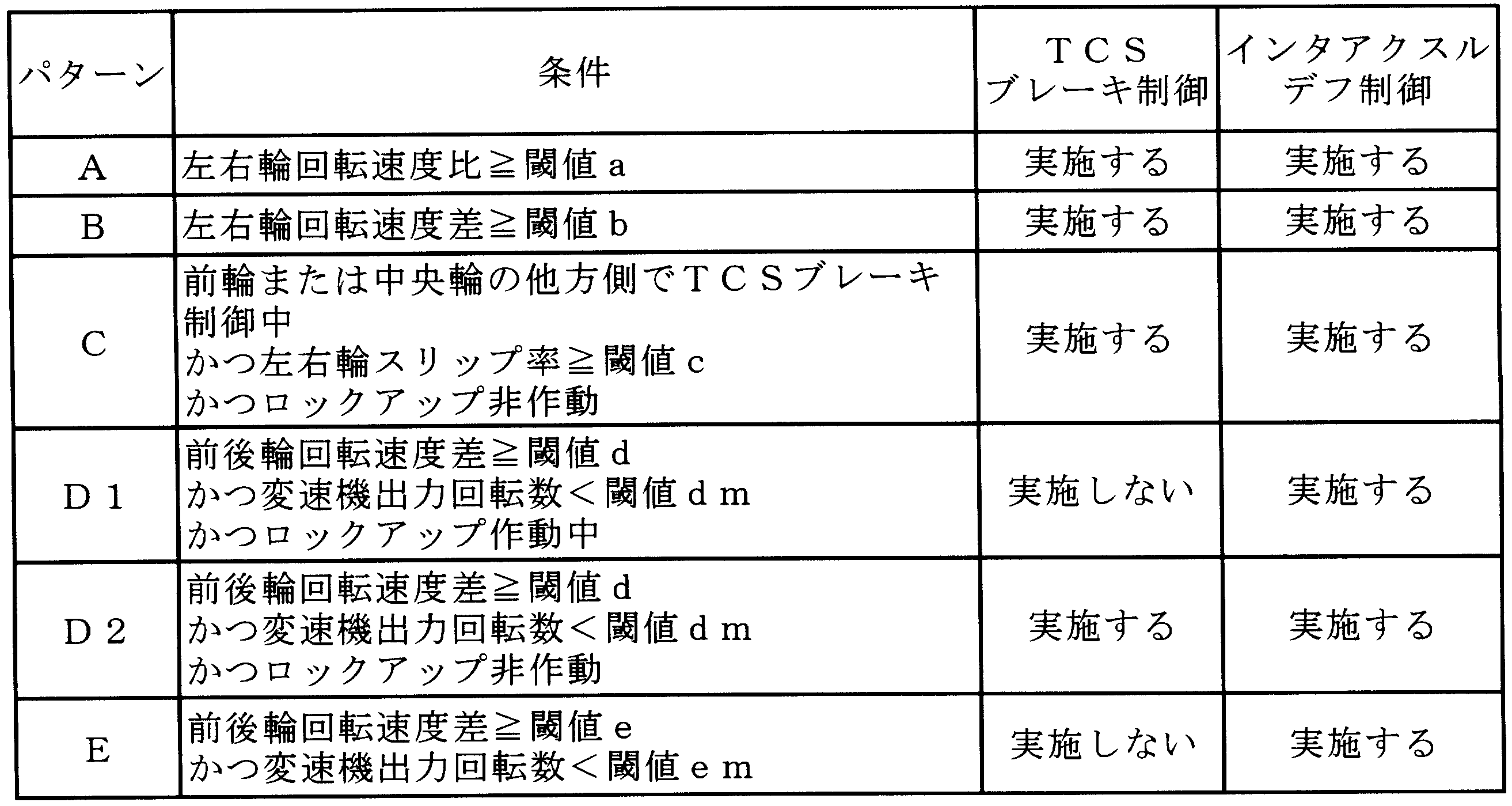
以下、図7~図9に従って、TCSコントローラ7におけるトラクションフォース推定部844の作用について詳しく説明する。
図7において、トラクションフォース推定部844は、先ずアクセルペダルがオンになっているか否かを判定する(処理S71)。
前輪4のトラクションフォースFの初期値の設定に際しては、先ず制御状態判定部844Aが、前輪TCSブレーキ制御フラグがセットされているか否かを判定する(処理S751)。
一方、処理S751で、前輪TCSブレーキ制御フラグがセットされていると判定された場合、制御状態判定部844Aは、さらに前輪4のTCSブレーキ制御が非制御状態から制御状態に切り換わったか否かを判定する(処理S753)。そして、前輪4のTCSブレーキ制御が非制御状態から制御状態に切り換わったと判定された場合、トラクションフォース初期値設定部844Bは、当該車輪4の入力駆動力Fin2が算出されていればこの入力駆動力Fin2で、そうでなければ入力駆動力Fin1で、当該車輪4のトラクションフォースFを初期化する(処理S754)。
なお、中央輪4のトラクションフォースFの初期値の設定は、図8のS761~S764に示すように、前輪4の場合と同じであるため、ここでの説明を省略する。
具体的に、トラクションフォース修正部844Cは、図9に示すように、制御偏差Sが、ゼロをその範囲に含む所定値D1~U1の範囲内にある場合は、トラクションフォースFを修正することなく、そのままの値を維持する。
以下、図10に示されるフローチャートおよび図11に従って、TCSブレーキ制御の詳細、特に制動機構制御手段84の目標ブレーキトルク算出部845A、目標ブレーキトルク判定部845B、基準車輪判定部845C、目標ブレーキトルク低減部845D、および制御指令生成部845Eの作用について詳しく説明する。
先ず、図10において、目標ブレーキトルク算出部845Aは、前述した式(16)および式(17)により、各車輪4の目標ブレーキトルクを算出する(処理S20)。また、目標ブレーキトルク算出部845Aは、式(18)を用いて、各車輪4の目標ブレーキトルクをそれぞれ目標ブレーキ圧に換算する。
例えば、前輪4および中央輪4の目標ブレーキ圧を示す図11において、基準車輪判定部845Cは、前輪4の目標ブレーキ圧Pfが、中央輪4の目標ブレーキ圧Pcよりも小さいことを認識して、前輪4を基準車輪と判定する。なお、実際には、基準車輪の判定や後述する目標ブレーキトルクの低減は、全ての駆動輪4の目標ブレーキ圧Pf,Pcを参照して行われるが、簡略化のため、図11では目標ブレーキ圧が最小となる前輪4と、何れか一方の中央輪4のみについて図示している。
ここで、図11に示すように、本実施形態の目標ブレーキトルク低減部845Dは、基準車輪である一方の前輪4の目標ブレーキ圧Pfとその圧力閾値Pthとの差圧ΔPfを算出する。そして、目標ブレーキトルク低減部845Dは、式(18)を用いて差圧ΔPfをブレーキトルクに換算し、基準車輪の目標ブレーキトルクとその閾値との差分に相当する値を算出する。ここで、ブレーキ圧に対するブレーキトルクのゲインは前後輪4で異なるので、これを調整するパラメータであるトルクカットゲインを用いて差圧ΔPfからブレーキトルクへの変換を行う。すなわち、目標ブレーキトルク低減部845Dは、メモリ71に記憶されているトルクカットゲインの値を差圧ΔPfに乗じてトルク低減量ΔTfに変換し、基準車輪の目標ブレーキトルクからトルク低減量ΔTfを減ずる。また、目標ブレーキトルク低減部845Dは、基準車輪ではない他方の前輪4についても、基準車輪と同じトルク低減量ΔTfを目標ブレーキトルクから減ずる。
制御指令生成部845Eは、各車輪4の目標ブレーキトルクに基づいて、電磁式比例制御弁612,613,622,623への制御指令の生成および出力をおこなう(処理S24)。これにより、電磁式比例制御弁612,613,622,623の開度が調整され、各車輪4の制動力が制御される。一方、TCSブレーキ制御が実施されていない場合、制御指令生成部845Eは、ソレノイド612A,613A,622A,623Aに対し電流値がゼロとなるような信号を出力する。
以下、図12に示されるフローチャートに従って、差動調整機構制御手段85の作用について、さらに詳しく説明する。
先ず、差動調整機構制御手段85は、インタアクスルデフ制御の実施要否を認識する(処理S30)。具体的に、差動調整機構制御手段85は、インタアクスルデフ制御フラグがオンか、または何れかの車輪でTCSブレーキ制御指令がゼロでない場合は、インタアクスルデフ制御が必要であることを認識し、そうでない場合は、インタアクスルデフ制御が不要であることを認識する。インタアクスルデフ制御が必要であることを認識した場合、差動調整機構制御手段85は、差動機構1Cの差動拘束力を最大の値とする制御指令(指令量100%)を生成し、差動調整機構1CAに出力する(処理S31)。また、差動調整機構制御手段85は、インタアクスルデフ制御終了カウンターをリセットする(処理S32)。
例えば、前記実施形態では、各車輪4の目標ブレーキトルクを目標ブレーキ圧に換算し、この目標ブレーキ圧を用いて、各目標ブレーキトルクが閾値以上となったか否かの判定、基準車輪の判定、および各目標ブレーキトルクの低減を行っていたがこれに限られず、例えば、目標ブレーキトルクそのものを用いて、これらの処理を行うようにしても良い。
また、基準車輪判定部845Cは、目標ブレーキトルクが最も小さい車輪4を基準車輪と判定しても良い。
さらに、目標ブレーキトルク低減部845Dは、各車輪4の目標ブレーキトルクがトルク閾値以上となった場合に、基準車輪の目標ブレーキトルクとトルク閾値との差分に応じて、各車輪4の目標ブレーキトルクを低減するようにしても良い。
さらに、前記実施形態では、車輪4の回転速度ωfl,ωfr,ωcl,ωcrに基づく推定車速を取得していたがこれに限られず、例えば、対地速度センサから車速を取得したり、GPS情報から車速Vを算出したりしてもよい。
F=Fin1+G1・S …(19)
[式20]
F=Fin2+G2・S …(20)
Claims (10)
- 各車輪に設けられる制動機構と、前後の車輪間の差動を調整する差動調整機構とを備えた建設機械の前記制動機構及び前記差動調整機構を制御するトラクションコントロール装置であって、
前記各車輪の回転速度を検出する回転速度検出手段と、
検出された前記各車輪の回転速度に基づいて、前記制動機構及び前記差動調整機構の制御を行うか否かを判定する制御開始判定手段と、
前記制御開始判定手段の判定結果に基づいて、前記制動機構の制御を行う制動機構制御手段と、
前記制御開始判定手段の判定結果に基づいて、前記差動調整機構の制御を行う差動調整機構制御手段とを備え、
前記制御開始判定手段は、
左右輪の回転速度差を算出する左右輪回転速度差算出部と、
前後輪の回転速度差を算出する前後輪回転速度差算出部と、
左右輪及び前後輪の少なくともいずれかの回転速度差が、予め記憶された所定の閾値以上となった場合に、前記制動機構及び前記差動調整機構の少なくともいずれかの制御開始をするか否かを判定する制御開始判定部とを備えていることを特徴とするトラクションコントロール装置。 - 請求項1に記載のトラクションコントロール装置において、
前後輪用の閾値及び左右輪用の閾値がそれぞれ設定され、
前記制御開始判定部は、
前記左右輪回転速度差が左右輪用の閾値以上となったときに、前記制動機構の制御を開始し、及び前記差動調整機構の制御を開始すると判定し、
前記前後輪回転速度差が前後輪用の閾値以上となったときに、前記差動調整機構の制御を開始すると判定することを特徴とするトラクションコントロール装置。 - 請求項1または請求項2に記載のトラクションコントロール装置において、
前記制御開始判定手段は、左右輪の回転速度比を下記式(1)により算出する左右輪回転速度比算出部を備え、
前記制御開始判定部は、左右輪の回転速度比が、予め記憶された所定の閾値以上となった場合に、前記制動機構及び前記差動調整機構の制御を開始すると判定することを特徴とするトラクションコントロール装置。
[式1]
ωee=|(ωl-ωr)/(ωl+ωr)| …(1)
ωee:回転速度比
ωl:左車輪回転速度
ωr:右車輪回転速度 - 請求項1ないし請求項3のいずれかに記載のトラクションコントロール装置において、
前記制御開始判定部は、トランスミッションのロックアップ状態に応じて、前記制動機構及び前記差動調整機構の少なくともいずれかの制御開始を判定することを特徴とするトラクションコントロール装置。 - 請求項1ないし請求項4のいずれかに記載のトラクションコントロール装置において、
前記建設機械は、前後に独立した車体フレームを有するアーティキュレート式の建設機械であり、
左右輪用の前記所定の閾値は、前後の車体フレームの屈折角に応じて変化することを特徴とするトラクションコントロール装置。 - 請求項1ないし請求項5のいずれかに記載のトラクションコントロール装置において、
前記建設機械の車速を取得する車速取得手段を備え、
前記制動機構制御手段は、
前記回転速度検出手段で検出されたいずれかの車輪の回転速度と、前記車速取得手段で取得された車速とに基づいて、当該車輪のスリップ率を算出するスリップ率算出部と、
算出されたスリップ率が、予め設定された目標スリップ率となるように、前記制動機構を制御する制動機構制御部とを備えていることを特徴とするトラクションコントロール装置。 - 請求項6に記載のトラクションコントロール装置において、
前記建設機械は、前後に独立した車体フレームを有するアーティキュレート式の建設機械であり、
前記目標スリップ率は、前後の車体フレームの屈折角に応じて変化することを特徴とするトラクションコントロール装置。 - 請求項1ないし請求項7のいずれかに記載のトラクションコントロール装置において、
前記制動機構制御手段は、スライディングモード制御則に基づいて、前記制動機構に与える制御量を演算することを特徴とするトラクションコントロール装置。 - 請求項1ないし請求項8のいずれかに記載のトラクションコントロール装置において、
前記差動調整機構制御手段は、前記制動機構の制御終了後の所定時間の間は前記差動調整機構の制御を継続し、前記所定時間経過後に前記差動調整機構の制御を終了することを特徴とするトラクションコントロール装置。 - 請求項1ないし請求項9のいずれかに記載のトラクションコントロール装置において、
前記制動機構制御手段により制御され、かつ前記各車輪の制動力を調整する電磁式比例制御弁を前記各車輪毎に備えていることを特徴とするトラクションコントロール装置。
Priority Applications (6)
| Application Number | Priority Date | Filing Date | Title |
|---|---|---|---|
| CN2009801385403A CN102171083B (zh) | 2008-12-26 | 2009-12-25 | 牵引力控制装置 |
| EP09835021.8A EP2374679B1 (en) | 2008-12-26 | 2009-12-25 | Traction control device |
| JP2010544153A JP5050102B2 (ja) | 2008-12-26 | 2009-12-25 | トラクションコントロール装置 |
| US13/139,470 US8725359B2 (en) | 2008-12-26 | 2009-12-25 | Traction control device |
| US13/172,383 US9145127B2 (en) | 2008-12-26 | 2011-06-29 | Traction control device |
| US13/175,107 US8352145B2 (en) | 2008-12-26 | 2011-07-01 | Traction control device |
Applications Claiming Priority (6)
| Application Number | Priority Date | Filing Date | Title |
|---|---|---|---|
| JP2008334068 | 2008-12-26 | ||
| JP2008-334068 | 2008-12-26 | ||
| JP2008334066 | 2008-12-26 | ||
| JP2008-334066 | 2008-12-26 | ||
| JP2008-334067 | 2008-12-26 | ||
| JP2008334067 | 2008-12-26 |
Related Child Applications (3)
| Application Number | Title | Priority Date | Filing Date |
|---|---|---|---|
| US13/139,470 A-371-Of-International US8725359B2 (en) | 2008-12-26 | 2009-12-25 | Traction control device |
| US13/172,383 Continuation-In-Part US9145127B2 (en) | 2008-12-26 | 2011-06-29 | Traction control device |
| US13/175,107 Continuation US8352145B2 (en) | 2008-12-26 | 2011-07-01 | Traction control device |
Publications (1)
| Publication Number | Publication Date |
|---|---|
| WO2010074225A1 true WO2010074225A1 (ja) | 2010-07-01 |
Family
ID=42287830
Family Applications (3)
| Application Number | Title | Priority Date | Filing Date |
|---|---|---|---|
| PCT/JP2009/071581 Ceased WO2010074225A1 (ja) | 2008-12-26 | 2009-12-25 | トラクションコントロール装置 |
| PCT/JP2009/071583 Ceased WO2010074227A1 (ja) | 2008-12-26 | 2009-12-25 | トラクションコントロール装置 |
| PCT/JP2009/071582 Ceased WO2010074226A1 (ja) | 2008-12-26 | 2009-12-25 | トラクションコントロール装置 |
Family Applications After (2)
| Application Number | Title | Priority Date | Filing Date |
|---|---|---|---|
| PCT/JP2009/071583 Ceased WO2010074227A1 (ja) | 2008-12-26 | 2009-12-25 | トラクションコントロール装置 |
| PCT/JP2009/071582 Ceased WO2010074226A1 (ja) | 2008-12-26 | 2009-12-25 | トラクションコントロール装置 |
Country Status (5)
| Country | Link |
|---|---|
| US (4) | US8463511B2 (ja) |
| EP (4) | EP2374674B1 (ja) |
| JP (4) | JP5002061B2 (ja) |
| CN (5) | CN102171083B (ja) |
| WO (3) | WO2010074225A1 (ja) |
Cited By (8)
| Publication number | Priority date | Publication date | Assignee | Title |
|---|---|---|---|---|
| US8352145B2 (en) | 2008-12-26 | 2013-01-08 | Komatsu Ltd. | Traction control device |
| US8504254B2 (en) | 2009-01-08 | 2013-08-06 | Komatsu Ltd. | Traction control apparatus |
| US8538635B2 (en) | 2009-01-08 | 2013-09-17 | Komatsu Ltd. | Vehicle speed estimator and traction control device |
| US9145127B2 (en) | 2008-12-26 | 2015-09-29 | Komatsu Ltd. | Traction control device |
| CN105270368A (zh) * | 2014-06-17 | 2016-01-27 | 株式会社万都 | 制动牵引力控制系统及其控制方法 |
| WO2016017014A1 (ja) * | 2014-07-31 | 2016-02-04 | 株式会社小松製作所 | 作業車両及び作業車両の制御方法 |
| CN109596367A (zh) * | 2019-01-06 | 2019-04-09 | 吴联凯 | 一种基于转速检测的摩托车检测系统和检测方法 |
| CN110352151A (zh) * | 2017-07-28 | 2019-10-18 | 日立建机株式会社 | 制动系统 |
Families Citing this family (55)
| Publication number | Priority date | Publication date | Assignee | Title |
|---|---|---|---|---|
| US9296295B2 (en) | 2008-12-22 | 2016-03-29 | Caterpillar Inc. | Machine control system utilizing inertial yaw sensor |
| US9126480B2 (en) | 2008-12-22 | 2015-09-08 | Caterpillar Inc. | Machine control system utilizing inertial yaw sensor |
| US8771140B2 (en) * | 2008-12-22 | 2014-07-08 | Caterpillar Inc. | Machine control system utilizing inertial yaw sensor |
| JP5749902B2 (ja) * | 2010-07-21 | 2015-07-15 | 川崎重工業株式会社 | 車両用トラクション制御装置 |
| DE102010039174A1 (de) | 2010-08-11 | 2012-02-16 | Robert Bosch Gmbh | Traktionshilfe-Funktion für Fahrzeuge mit mehreren angetriebenen Achsen |
| DE102010062947A1 (de) * | 2010-12-13 | 2012-06-14 | Zf Friedrichshafen Ag | Verfahren zur Ansteuerung eines Retarders eines Kraftfahrzeuges |
| JP5010042B1 (ja) * | 2011-06-10 | 2012-08-29 | 株式会社小松製作所 | ダンプトラック |
| CN102975720B (zh) * | 2011-09-02 | 2015-11-04 | 同济大学 | 车辆纵向车速测算装置、方法及使用该装置的车辆 |
| US9056624B2 (en) * | 2012-11-14 | 2015-06-16 | Deere & Company | Front wheel drive control |
| US8880301B2 (en) | 2012-11-14 | 2014-11-04 | Deere & Company | Torque control for front wheel drive |
| KR102024384B1 (ko) * | 2012-12-26 | 2019-11-04 | 현대모비스 주식회사 | 차량의 선회 제어방법 및 차량용 선회 제어시스템 |
| US8790217B1 (en) * | 2013-03-01 | 2014-07-29 | Honda Motor Co., Ltd. | Vehicles including differential lock controller and methods |
| US10029566B2 (en) * | 2013-10-09 | 2018-07-24 | Eaton Intelligent Power Limited | Method for limiting clutch torque to reduce high MU wheel slip |
| ITMO20130286A1 (it) * | 2013-10-11 | 2015-04-11 | Cnh Italia Spa | Metodi di frenatura per un veicolo e relativi apparati. |
| TWI558584B (zh) * | 2014-01-02 | 2016-11-21 | Kwang Yang Motor Co | Vehicle power control device and method for vehicle differential controller |
| FR3017095B1 (fr) * | 2014-02-03 | 2017-05-12 | Renault Sas | Procede de suivi de trajectoire d'un vehicule automobile et vehicule associe |
| SE538011C2 (sv) * | 2014-02-03 | 2016-02-09 | Atlas Copco Rock Drills Ab | Förfarande, system och datorprogram för styrning av framdrivning av en borrigg jämte borrigg |
| KR101534749B1 (ko) * | 2014-05-15 | 2015-07-07 | 현대자동차 주식회사 | 하이브리드 차량의 토크 저감 제어 방법 |
| US10113929B2 (en) | 2014-08-21 | 2018-10-30 | Caterpillar Paving Products Inc. | Use of wheel slip to help identify soft spots |
| US9242648B1 (en) * | 2014-09-05 | 2016-01-26 | Caterpillar Inc. | Boosting parking brake drive-through torque |
| JP6267090B2 (ja) * | 2014-09-29 | 2018-01-24 | 日立建機株式会社 | 運搬車両の走行停止制御装置およびそれを備えた運搬車両 |
| KR102352410B1 (ko) * | 2014-11-24 | 2022-01-19 | 현대모비스 주식회사 | 차량의 구동력 제어 장치 및 그 제어 방법 |
| WO2016114282A1 (ja) * | 2015-01-13 | 2016-07-21 | 本田技研工業株式会社 | 駆動装置の制御装置及び制御方法ならびに記録媒体 |
| JP2018069743A (ja) | 2015-02-26 | 2018-05-10 | ヤマハ発動機株式会社 | 駆動トルク制御装置、駆動源ユニットおよび車両 |
| DE112016001432T5 (de) * | 2015-03-27 | 2017-12-14 | Calsonic Kansei Corporation | Antriebsleistungssteuerungsvorrichtung für elektrofahrzeug |
| WO2017030774A1 (en) | 2015-08-14 | 2017-02-23 | Crown Equipment Corporation | Model based diagnostics based on steering model |
| CA2991312C (en) * | 2015-08-14 | 2023-09-19 | Crown Equipment Corporation | Steering and traction applications for determining a steering control attribute and a traction control attribute |
| DE102016013054A1 (de) * | 2015-12-09 | 2017-06-14 | Wabco Gmbh | Verfahren zum Einstellen von Bremsdrücken eines Fahrzeugs, Bremsanlage zur Durchführung des Verfahrens sowie Fahrzeug |
| JP6298037B2 (ja) * | 2015-12-24 | 2018-03-20 | トヨタ自動車株式会社 | 駆動装置の制御システム |
| US9873433B2 (en) | 2016-03-09 | 2018-01-23 | Bendix Commercial Vehicle Systems Llc | System and method for controlling torque to a driveshaft |
| WO2018132170A1 (en) | 2017-01-13 | 2018-07-19 | Crown Equipment Corporation | High speed straight ahead tiller desensitization |
| KR102350703B1 (ko) | 2017-01-13 | 2022-01-13 | 크라운 이큅먼트 코포레이션 | 스티어 휠 동역학에 기초한 견인 속도 복구 |
| EP3625111B1 (en) * | 2017-05-15 | 2021-12-01 | Volvo Construction Equipment AB | A method and control unit for preventing a rollover situation of an articulated vehicle |
| DE102017008949A1 (de) * | 2017-09-25 | 2019-03-28 | Lucas Automotive Gmbh | Radschlupfregelung für ein Kraftfahrzeug |
| US11124166B2 (en) * | 2017-09-26 | 2021-09-21 | Hitachi Construction Machinery Co., Ltd. | Vehicular brake system |
| CN109910850B (zh) * | 2017-12-13 | 2020-06-19 | 比亚迪股份有限公司 | 车辆及其制动控制方法和装置 |
| DE102018212064A1 (de) * | 2018-07-19 | 2020-01-23 | Robert Bosch Gmbh | Verfahren zur Fahrerassistenz, bei dem ein Fahrzeug ein Fahrmanöver automatisch ausführt, sowie Steuer- und Regeleinrichtung für eine Bremseinrichtung eines Fahrzeugs |
| JP7266383B2 (ja) * | 2018-10-26 | 2023-04-28 | 株式会社小松製作所 | 作業機械およびその制御方法 |
| JP6748177B2 (ja) * | 2018-11-14 | 2020-08-26 | 本田技研工業株式会社 | 車両制御装置、車両制御方法、およびプログラム |
| US11117583B2 (en) * | 2019-03-15 | 2021-09-14 | Caterpillar Inc. | Brake system for an articulated vehicle |
| CN112298188A (zh) * | 2019-07-24 | 2021-02-02 | 奥迪股份公司 | 辅助驾驶方法、系统、计算机设备和存储介质 |
| CN112572387B (zh) * | 2020-12-10 | 2022-02-01 | 浙江吉利控股集团有限公司 | 一种车辆的制动控制系统、车辆及制动控制方法 |
| CN112644457B (zh) * | 2021-01-08 | 2022-01-11 | 江苏大学 | 一种分布式驱动车辆转向稳定性控制系统及其控制方法 |
| WO2022262937A1 (en) | 2021-06-14 | 2022-12-22 | Volvo Truck Corporation | A method for controlling propulsion of a heavy-duty vehicle |
| CN115126843B (zh) * | 2021-09-18 | 2025-12-16 | 长城汽车股份有限公司 | 差速锁系统的控制方法、装置和车辆 |
| CN114001141B (zh) * | 2021-11-02 | 2024-03-05 | 北京汽车集团越野车有限公司 | 电子差速锁控制方法及装置 |
| EP4219252B1 (en) * | 2022-01-28 | 2025-09-10 | Volvo Truck Corporation | A method for controlling a heavy-duty vehicle |
| US11808342B2 (en) | 2022-02-08 | 2023-11-07 | Dana Automotive Systems Group, Llc | Differential carrier |
| CN114623977A (zh) * | 2022-03-12 | 2022-06-14 | 北京化工大学 | 一种基于微速差的桨扇同轴对转结构自动平衡控制方法 |
| CN114922247B (zh) * | 2022-05-20 | 2023-07-28 | 江苏电子信息职业学院 | 一种四轮独立电驱动装载机打滑的判定方法和控制方法 |
| CN115366879B (zh) * | 2022-07-29 | 2024-04-12 | 广州汽车集团股份有限公司 | 车辆的控制方法、装置、车辆及存储介质 |
| US12377852B2 (en) | 2023-02-01 | 2025-08-05 | Ford Global Technologies, Llc | Methods and system for operating a vehicle in sand |
| CN116811811B (zh) * | 2023-06-21 | 2026-01-30 | 长城汽车股份有限公司 | 一种交叉轴工况的控制方法、装置、车辆和存储介质 |
| CN117930666B (zh) * | 2024-03-25 | 2024-05-24 | 华东交通大学 | 基于快速变幂次趋近律的动车组控制方法、设备及介质 |
| CN119699053B (zh) * | 2024-12-10 | 2025-07-15 | 青岛科瑞特传动科技有限公司 | 一种收割机底盘智能液压控制系统 |
Citations (6)
| Publication number | Priority date | Publication date | Assignee | Title |
|---|---|---|---|---|
| JPS5993560A (ja) * | 1982-11-17 | 1984-05-30 | Komatsu Ltd | スリップ防止装置 |
| JPH0516686A (ja) * | 1991-07-09 | 1993-01-26 | Mazda Motor Corp | 車両の走行状態判定装置および車両の動力伝達制御装置 |
| JP2001277896A (ja) | 2000-03-29 | 2001-10-10 | Komatsu Ltd | インタアクスルデフ装置及びその制御方法 |
| JP2002029401A (ja) * | 2000-07-18 | 2002-01-29 | Mazda Motor Corp | 車両の差動制限装置 |
| JP2003237398A (ja) * | 2002-02-12 | 2003-08-27 | Hitachi Unisia Automotive Ltd | 四輪駆動車の駆動力配分制御装置 |
| JP2004175347A (ja) | 2002-11-27 | 2004-06-24 | Caterpillar Inc | 電子牽引制御システム |
Family Cites Families (95)
| Publication number | Priority date | Publication date | Assignee | Title |
|---|---|---|---|---|
| JPS62196442A (ja) | 1986-02-24 | 1987-08-29 | Hitachi Ltd | 自動変速制御装置の回転数処理方法 |
| JP2593478B2 (ja) | 1987-07-24 | 1997-03-26 | マツダ株式会社 | 車両のトラクション制御装置 |
| JPH07108633B2 (ja) | 1987-11-30 | 1995-11-22 | 日産自動車株式会社 | 車両用駆動力制御装置 |
| GB8814931D0 (en) | 1988-06-23 | 1988-07-27 | Lucas Ind Plc | Vehicle speed estimation in anti-lock braking systems |
| JP2677832B2 (ja) | 1988-07-29 | 1997-11-17 | マツダ株式会社 | 自動車のスリップ制御装置 |
| JP2659766B2 (ja) | 1988-09-30 | 1997-09-30 | マツダ株式会社 | 4輪駆動車のスリップ制御装置 |
| JPH02191844A (ja) | 1989-01-20 | 1990-07-27 | Mitsubishi Motors Corp | エンジントルク制御装置 |
| US5155686A (en) | 1989-05-31 | 1992-10-13 | Honda Giken Hogyo Kabushiki Kaisha | Physical quantity control device usable in vehicle motion control |
| JP2704771B2 (ja) | 1989-10-18 | 1998-01-26 | 本田技研工業株式会社 | 車両のトラクション制御方法 |
| JP2902059B2 (ja) | 1990-06-21 | 1999-06-07 | マツダ株式会社 | 車両のトラクション制御装置 |
| JP2935379B2 (ja) * | 1991-02-14 | 1999-08-16 | マツダ株式会社 | 車両のスリップ制御装置 |
| JP2892855B2 (ja) | 1991-04-15 | 1999-05-17 | マツダ株式会社 | 車両のトラクション制御装置 |
| US5535124A (en) | 1991-10-04 | 1996-07-09 | Caterpillar Inc. | Method and apparatus for controlling differentially driven wheel-slip for an articulated machine |
| DE69304144T2 (de) | 1992-06-15 | 1997-01-09 | Mitsubishi Motors Corp | Vorrichtung und Verfahren zur Verteilung des Antriebsmomentes auf das rechte/linke Rad eines Kraftfahrzeuges |
| DE4229560B4 (de) | 1992-09-04 | 2009-07-23 | Robert Bosch Gmbh | Antriebsschlupfregelsystem |
| US5456526A (en) * | 1992-11-27 | 1995-10-10 | Akebono Brake Industry Co., Ltd. | ABS control for individual axles of a three axle vehicle |
| DE4327507C2 (de) | 1993-08-16 | 1996-07-18 | Steyr Daimler Puch Ag | Vorrichtung zur Steuerung der Kupplungen im Antriebsstrang eines Kraftfahrzeuges |
| JPH07186926A (ja) * | 1993-12-28 | 1995-07-25 | Mazda Motor Corp | 車両のトラクション制御装置 |
| JP3085092B2 (ja) | 1994-06-29 | 2000-09-04 | トヨタ自動車株式会社 | 加速スリップ制御装置 |
| JP3617680B2 (ja) * | 1995-01-31 | 2005-02-09 | 富士重工業株式会社 | 4輪駆動車のトラクション制御装置 |
| JPH08258588A (ja) | 1995-03-27 | 1996-10-08 | Mazda Motor Corp | 車両における路面状態検出装置 |
| JP3412363B2 (ja) | 1995-09-27 | 2003-06-03 | トヨタ自動車株式会社 | 車輌の車体速度推定装置及び車輪の自由回転速度推定装置 |
| DE19717113B4 (de) | 1996-04-26 | 2010-04-08 | DENSO CORPORATION, Kariya-shi | Bremskraft-Regelsystem für Kraftfahrzeuge |
| JP4118350B2 (ja) | 1996-04-26 | 2008-07-16 | 株式会社デンソー | 車両用運動特性制御装置 |
| JPH1029524A (ja) | 1996-07-15 | 1998-02-03 | Toyota Motor Corp | 車輪スリップ制御装置 |
| US6122585A (en) * | 1996-08-20 | 2000-09-19 | Kabushiki Kaisha Toyota Chuo Kenkyusho | Anti-lock braking system based on an estimated gradient of friction torque, method of determining a starting point for anti-lock brake control, and wheel-behavior-quantity servo control means equipped with limit determination means |
| US5978726A (en) * | 1996-09-18 | 1999-11-02 | Denso Corporation | Driving torque control method and apparatus for a four-wheel drive vehicle |
| JP3296987B2 (ja) | 1997-02-20 | 2002-07-02 | アイシン精機株式会社 | 四輪駆動車のトラクション制御装置 |
| JP4215861B2 (ja) | 1997-08-11 | 2009-01-28 | 富士重工業株式会社 | 4輪駆動車の動力配分制御装置 |
| JP3937524B2 (ja) * | 1997-09-30 | 2007-06-27 | トヨタ自動車株式会社 | 車輌の制駆動力制御装置 |
| EP0963892B1 (en) | 1998-06-09 | 2007-02-14 | Fuji Jukogyo Kabushiki Kaisha | Torque distribution control apparatus for 4 wheel driven vehicle |
| US6185920B1 (en) | 1998-07-20 | 2001-02-13 | Lonmore L.C. | Zero radius steering, compact stand-on mower and utility tractor |
| US6913326B1 (en) * | 1998-08-28 | 2005-07-05 | Toyota Jidosha Kabushiki Kaisha | Apparatus for increasing brake cylinder pressure by controlling pump motor and reducing the pressure by controlling electric energy applied to control valve |
| US6205379B1 (en) | 1998-09-04 | 2001-03-20 | Toyota Jidosha Kabushiki Kaisha | Controller for hybrid vehicle wherein one and the other of front and rear wheels are respectively driven by engine and electric motor |
| JP3607990B2 (ja) | 1999-06-07 | 2005-01-05 | トヨタ自動車株式会社 | 車両用トラクション制御装置 |
| JP3680216B2 (ja) | 1999-06-08 | 2005-08-10 | トヨタ自動車株式会社 | 車輌用トラクション制御装置 |
| JP3716333B2 (ja) | 1999-09-09 | 2005-11-16 | 日産自動車株式会社 | 四輪駆動車の駆動力制御装置 |
| KR20010093817A (ko) * | 1999-10-12 | 2001-10-29 | 클라우스 포스, 게오르그 뮐러 | 차량의 차동 차단 기능을 실행하기 위한 방법 및 장치 |
| JP2001122099A (ja) | 1999-10-22 | 2001-05-08 | Toyota Motor Corp | 駆動スリップ制御装置 |
| JP3740005B2 (ja) | 1999-11-01 | 2006-01-25 | トヨタ自動車株式会社 | 制動トルク制御装置 |
| JP3777937B2 (ja) | 2000-02-10 | 2006-05-24 | トヨタ自動車株式会社 | 4輪駆動車用トラクション制御装置 |
| JP3592192B2 (ja) | 2000-04-20 | 2004-11-24 | トヨタ自動車株式会社 | タイヤ空気圧判定装置 |
| JP3607985B2 (ja) | 2000-07-14 | 2005-01-05 | トヨタ自動車株式会社 | 車輌の車体速度推定装置及び制御装置 |
| JP2002037047A (ja) * | 2000-07-24 | 2002-02-06 | Aisin Seiki Co Ltd | 車両の制動制御装置 |
| JP2002087095A (ja) | 2000-09-12 | 2002-03-26 | Komatsu Ltd | 車両のタイヤロック防止装置 |
| JP4234893B2 (ja) | 2000-09-12 | 2009-03-04 | 株式会社小松製作所 | シリンダの作動制御装置 |
| JP2002104156A (ja) * | 2000-09-27 | 2002-04-10 | Toyota Motor Corp | 車輌の制駆動力制御装置 |
| JP2004525017A (ja) * | 2000-12-20 | 2004-08-19 | キャタピラー インコーポレイテッド | 牽引制御装置を有する建設機械 |
| DE10160045B4 (de) * | 2000-12-30 | 2005-09-15 | Robert Bosch Gmbh | System und Verfahren zur Überwachung des Fahrverhaltens eines Kraftfahrzeugs |
| EP1347900A1 (de) | 2000-12-30 | 2003-10-01 | Robert Bosch Gmbh | Verfahren und system zur steuerung und/oder regelung des fahrverhaltens eines kraftfahrzeuges |
| JP2003104186A (ja) | 2001-09-27 | 2003-04-09 | Nissan Motor Co Ltd | 4輪駆動車の加速スリップ制御装置 |
| US6702048B2 (en) | 2001-11-15 | 2004-03-09 | Caterpillar Inc | System and method for calibrating a differential steering system |
| FR2832682A1 (fr) | 2001-11-23 | 2003-05-30 | Conception & Dev Michelin Sa | Dispositif de commande pour direction electrique active |
| AT6086U1 (de) * | 2002-04-12 | 2003-04-25 | Steyr Powertrain Ag & Co Kg | Kraftfahrzeug mit einem bremssystem und einem antriebssystem |
| US6741922B2 (en) | 2002-05-30 | 2004-05-25 | Bendix Commercial Vehicle Systems Llc | Antilock braking system based roll over prevention |
| JP2004017721A (ja) * | 2002-06-13 | 2004-01-22 | Hitachi Unisia Automotive Ltd | 四輪駆動車の制御装置 |
| JP2004090886A (ja) | 2002-09-04 | 2004-03-25 | Advics:Kk | 車両のトラクション制御装置 |
| US7104617B2 (en) * | 2002-09-06 | 2006-09-12 | Ford Motor Company | Independent braking and controllability control method and system for a vehicle with regenerative braking |
| JP4193971B2 (ja) * | 2002-09-10 | 2008-12-10 | 株式会社アドヴィックス | 車両の運動制御装置 |
| DE10245033B4 (de) | 2002-09-26 | 2005-11-10 | Dr.Ing.H.C. F. Porsche Ag | Verfahren zur Regelung des Fahrverhaltens mittels Einflußnahme auf die Regelung der Längssperre für eine feste Momentenverteilung |
| JP4263459B2 (ja) | 2002-10-25 | 2009-05-13 | 富士重工業株式会社 | 車両の差動制限制御装置 |
| JP2004150304A (ja) * | 2002-10-29 | 2004-05-27 | Komatsu Ltd | エンジンの制御装置 |
| US6923514B1 (en) | 2003-03-12 | 2005-08-02 | Kelsey-Hayes Company | Electronic brake control system |
| JP4258265B2 (ja) * | 2003-04-30 | 2009-04-30 | 日産自動車株式会社 | 車両挙動制御装置 |
| JP4213545B2 (ja) * | 2003-09-05 | 2009-01-21 | 株式会社ジェイテクト | 車輪のグリップ度推定装置、及び該装置を備えた車両の運動制御装置 |
| JP2005098784A (ja) * | 2003-09-24 | 2005-04-14 | Advics:Kk | 車輪速度演算装置およびそれを備えたアンチスキッド制御装置 |
| US7016776B2 (en) | 2004-03-19 | 2006-03-21 | Ford Global Technologies, Llc | Magnetic powder torque transfer clutch for controlling slip across a differential mechanism |
| JP3998000B2 (ja) | 2004-03-24 | 2007-10-24 | 株式会社日立製作所 | ハイブリッド四輪駆動車の制御装置およびハイブリッド四輪駆動車 |
| JP4277755B2 (ja) * | 2004-07-16 | 2009-06-10 | 日産自動車株式会社 | 車両用旋回走行制御装置 |
| US7276014B2 (en) | 2004-11-05 | 2007-10-02 | Ntn Corporation | Vehicle stability control system for enhanced transfer case compatibility |
| JP4704767B2 (ja) | 2004-12-10 | 2011-06-22 | Gknドライブラインジャパン株式会社 | 車両駆動制御装置 |
| JP4506518B2 (ja) * | 2005-03-14 | 2010-07-21 | マツダ株式会社 | 駆動力制御装置 |
| JP4301212B2 (ja) * | 2005-06-03 | 2009-07-22 | 日産自動車株式会社 | 車両の制御装置 |
| JP4696224B2 (ja) * | 2005-07-19 | 2011-06-08 | 三菱自動車工業株式会社 | 4輪駆動車の差動制限制御装置 |
| US7770909B2 (en) * | 2005-07-21 | 2010-08-10 | Deere & Company | Articulated vehicle stabilization system |
| JP4604926B2 (ja) | 2005-09-09 | 2011-01-05 | 株式会社アドヴィックス | 車両のトラクション制御装置、及び車両のトラクション制御方法 |
| JP4701977B2 (ja) * | 2005-10-06 | 2011-06-15 | 株式会社デンソー | 車載ネットワークの診断システム及び車載制御装置 |
| US7455142B2 (en) | 2005-12-05 | 2008-11-25 | Honda Motor Co., Ltd. | Scaling of side-to-side torque bias to improve cornering in a programmable four wheel drive system |
| JP4878160B2 (ja) | 2006-01-04 | 2012-02-15 | クラリオン株式会社 | 交通情報表示方法及びナビゲーションシステム |
| JP4844720B2 (ja) * | 2006-03-07 | 2011-12-28 | 三菱自動車工業株式会社 | 車両の差動制限制御装置 |
| US7766104B2 (en) * | 2006-04-20 | 2010-08-03 | Caterpillar Inc | Differential lock control in articulated machine |
| WO2008029524A1 (en) * | 2006-09-07 | 2008-03-13 | Yokohama National University | Slip ratio estimating device and slip ratio control device |
| US7444222B2 (en) | 2006-09-28 | 2008-10-28 | Gm Global Technology Operations, Inc. | Method and apparatus for generating a cornering-corrected eLSD control signal |
| JP4333729B2 (ja) * | 2006-11-21 | 2009-09-16 | トヨタ自動車株式会社 | 車両挙動制御装置 |
| US20080177495A1 (en) | 2007-01-20 | 2008-07-24 | Josh Todd Gold | Automated measurement derivation |
| US7770681B2 (en) * | 2007-04-11 | 2010-08-10 | Caterpillar Inc | Traction control method in machine using lockable differential |
| US8061464B2 (en) | 2008-04-09 | 2011-11-22 | Ford Global Technologies, Llc | Traction and stability control system and method for a vehicle with mechanically independent front and rear traction wheels |
| WO2009128815A1 (en) * | 2008-04-14 | 2009-10-22 | Deere & Company | Traction control method and apparatus for a vehicle with independent drives |
| US9086104B2 (en) * | 2008-12-22 | 2015-07-21 | Caterpillar Inc. | System and method for controlling wheel spin and wheel slip on a machine having differentially driven wheels |
| US8463511B2 (en) | 2008-12-26 | 2013-06-11 | Komatsu Ltd. | Traction control device |
| US9145127B2 (en) | 2008-12-26 | 2015-09-29 | Komatsu Ltd. | Traction control device |
| CN102171077B (zh) | 2009-01-08 | 2013-10-16 | 株式会社小松制作所 | 牵引控制装置 |
| EP2374680B1 (en) | 2009-01-08 | 2013-07-17 | Komatsu Ltd. | Vehicle speed estimator and traction control device |
| JP4866452B2 (ja) | 2009-08-05 | 2012-02-01 | 本田技研工業株式会社 | 四輪駆動車両のトルク配分制御装置 |
| US8626404B2 (en) * | 2010-11-19 | 2014-01-07 | Caterpillar Inc. | Motor grader wheel slip control for cut to grade |
-
2009
- 2009-12-25 US US13/140,664 patent/US8463511B2/en active Active
- 2009-12-25 CN CN2009801385403A patent/CN102171083B/zh active Active
- 2009-12-25 US US13/139,470 patent/US8725359B2/en active Active
- 2009-12-25 CN CN201110189459.7A patent/CN102320300B/zh active Active
- 2009-12-25 EP EP09835023.4A patent/EP2374674B1/en active Active
- 2009-12-25 JP JP2010544154A patent/JP5002061B2/ja active Active
- 2009-12-25 US US13/140,537 patent/US8725360B2/en active Active
- 2009-12-25 JP JP2010544155A patent/JP5002062B2/ja active Active
- 2009-12-25 EP EP09835021.8A patent/EP2374679B1/en active Active
- 2009-12-25 CN CN2009801386035A patent/CN102171078B/zh active Active
- 2009-12-25 JP JP2010544153A patent/JP5050102B2/ja active Active
- 2009-12-25 CN CN200980138354XA patent/CN102171076B/zh active Active
- 2009-12-25 EP EP11006813.7A patent/EP2407335B1/en active Active
- 2009-12-25 CN CN201310644172.8A patent/CN103693039B/zh active Active
- 2009-12-25 WO PCT/JP2009/071581 patent/WO2010074225A1/ja not_active Ceased
- 2009-12-25 WO PCT/JP2009/071583 patent/WO2010074227A1/ja not_active Ceased
- 2009-12-25 EP EP09835022.6A patent/EP2374673B1/en active Active
- 2009-12-25 WO PCT/JP2009/071582 patent/WO2010074226A1/ja not_active Ceased
-
2011
- 2011-06-30 JP JP2011146646A patent/JP5130388B2/ja active Active
- 2011-07-01 US US13/175,107 patent/US8352145B2/en active Active
Patent Citations (6)
| Publication number | Priority date | Publication date | Assignee | Title |
|---|---|---|---|---|
| JPS5993560A (ja) * | 1982-11-17 | 1984-05-30 | Komatsu Ltd | スリップ防止装置 |
| JPH0516686A (ja) * | 1991-07-09 | 1993-01-26 | Mazda Motor Corp | 車両の走行状態判定装置および車両の動力伝達制御装置 |
| JP2001277896A (ja) | 2000-03-29 | 2001-10-10 | Komatsu Ltd | インタアクスルデフ装置及びその制御方法 |
| JP2002029401A (ja) * | 2000-07-18 | 2002-01-29 | Mazda Motor Corp | 車両の差動制限装置 |
| JP2003237398A (ja) * | 2002-02-12 | 2003-08-27 | Hitachi Unisia Automotive Ltd | 四輪駆動車の駆動力配分制御装置 |
| JP2004175347A (ja) | 2002-11-27 | 2004-06-24 | Caterpillar Inc | 電子牽引制御システム |
Non-Patent Citations (1)
| Title |
|---|
| See also references of EP2374679A4 * |
Cited By (16)
| Publication number | Priority date | Publication date | Assignee | Title |
|---|---|---|---|---|
| US8352145B2 (en) | 2008-12-26 | 2013-01-08 | Komatsu Ltd. | Traction control device |
| US8463511B2 (en) | 2008-12-26 | 2013-06-11 | Komatsu Ltd. | Traction control device |
| US9145127B2 (en) | 2008-12-26 | 2015-09-29 | Komatsu Ltd. | Traction control device |
| US8725360B2 (en) | 2008-12-26 | 2014-05-13 | Komatsu Ltd. | Traction control device |
| US8682535B2 (en) | 2009-01-08 | 2014-03-25 | Komatsu Ltd. | Vehicle speed estimator and traction control device |
| US8694212B2 (en) | 2009-01-08 | 2014-04-08 | Komatsu Ltd. | Vehicle speed estimator and traction control device |
| US8538635B2 (en) | 2009-01-08 | 2013-09-17 | Komatsu Ltd. | Vehicle speed estimator and traction control device |
| US8989969B2 (en) | 2009-01-08 | 2015-03-24 | Komatsu Ltd. | Traction control apparatus |
| US8504254B2 (en) | 2009-01-08 | 2013-08-06 | Komatsu Ltd. | Traction control apparatus |
| CN105270368A (zh) * | 2014-06-17 | 2016-01-27 | 株式会社万都 | 制动牵引力控制系统及其控制方法 |
| WO2016017014A1 (ja) * | 2014-07-31 | 2016-02-04 | 株式会社小松製作所 | 作業車両及び作業車両の制御方法 |
| JPWO2016017014A1 (ja) * | 2014-07-31 | 2017-05-18 | 株式会社小松製作所 | 作業車両及び作業車両の制御方法 |
| US10124805B2 (en) | 2014-07-31 | 2018-11-13 | Komatsu Ltd. | Work vehicle and control method for work vehicle |
| CN110352151A (zh) * | 2017-07-28 | 2019-10-18 | 日立建机株式会社 | 制动系统 |
| CN110352151B (zh) * | 2017-07-28 | 2021-07-09 | 日立建机株式会社 | 制动系统 |
| CN109596367A (zh) * | 2019-01-06 | 2019-04-09 | 吴联凯 | 一种基于转速检测的摩托车检测系统和检测方法 |
Also Published As
Similar Documents
| Publication | Publication Date | Title |
|---|---|---|
| JP5050102B2 (ja) | トラクションコントロール装置 | |
| US9145127B2 (en) | Traction control device | |
| US8764124B2 (en) | Brake control apparatus | |
| JP4179392B1 (ja) | 車両の旋回挙動制御装置 | |
| US9150203B2 (en) | Vehicle braking control device | |
| KR102881929B1 (ko) | 차량의 자세 제어 방법 | |
| CN108621787A (zh) | 四轮驱动车辆的控制装置 | |
| JP2013018326A (ja) | 車両旋回挙動制御装置 | |
| US10124781B2 (en) | Vehicle brake device | |
| JP4626550B2 (ja) | 車両の旋回挙動制御装置 |
Legal Events
| Date | Code | Title | Description |
|---|---|---|---|
| WWE | Wipo information: entry into national phase |
Ref document number: 200980138540.3 Country of ref document: CN |
|
| 121 | Ep: the epo has been informed by wipo that ep was designated in this application |
Ref document number: 09835021 Country of ref document: EP Kind code of ref document: A1 |
|
| WWE | Wipo information: entry into national phase |
Ref document number: 2010544153 Country of ref document: JP |
|
| REEP | Request for entry into the european phase |
Ref document number: 2009835021 Country of ref document: EP |
|
| WWE | Wipo information: entry into national phase |
Ref document number: 2009835021 Country of ref document: EP |
|
| WWE | Wipo information: entry into national phase |
Ref document number: 13139470 Country of ref document: US |
|
| NENP | Non-entry into the national phase |
Ref country code: DE |