WO2010074307A1 - 原油タンカー用耐食鋼材 - Google Patents
原油タンカー用耐食鋼材 Download PDFInfo
- Publication number
- WO2010074307A1 WO2010074307A1 PCT/JP2009/071841 JP2009071841W WO2010074307A1 WO 2010074307 A1 WO2010074307 A1 WO 2010074307A1 JP 2009071841 W JP2009071841 W JP 2009071841W WO 2010074307 A1 WO2010074307 A1 WO 2010074307A1
- Authority
- WO
- WIPO (PCT)
- Prior art keywords
- mass
- corrosion
- steel material
- less
- crude oil
- Prior art date
- Legal status (The legal status is an assumption and is not a legal conclusion. Google has not performed a legal analysis and makes no representation as to the accuracy of the status listed.)
- Ceased
Links
Images

Classifications
-
- C—CHEMISTRY; METALLURGY
- C22—METALLURGY; FERROUS OR NON-FERROUS ALLOYS; TREATMENT OF ALLOYS OR NON-FERROUS METALS
- C22C—ALLOYS
- C22C38/00—Ferrous alloys, e.g. steel alloys
- C22C38/18—Ferrous alloys, e.g. steel alloys containing chromium
- C22C38/20—Ferrous alloys, e.g. steel alloys containing chromium with copper
-
- C—CHEMISTRY; METALLURGY
- C22—METALLURGY; FERROUS OR NON-FERROUS ALLOYS; TREATMENT OF ALLOYS OR NON-FERROUS METALS
- C22C—ALLOYS
- C22C38/00—Ferrous alloys, e.g. steel alloys
- C22C38/02—Ferrous alloys, e.g. steel alloys containing silicon
-
- C—CHEMISTRY; METALLURGY
- C21—METALLURGY OF IRON
- C21D—MODIFYING THE PHYSICAL STRUCTURE OF FERROUS METALS; GENERAL DEVICES FOR HEAT TREATMENT OF FERROUS OR NON-FERROUS METALS OR ALLOYS; MAKING METAL MALLEABLE, e.g. BY DECARBURISATION OR TEMPERING
- C21D9/00—Heat treatment, e.g. annealing, hardening, quenching or tempering, adapted for particular articles; Furnaces therefor
- C21D9/46—Heat treatment, e.g. annealing, hardening, quenching or tempering, adapted for particular articles; Furnaces therefor for sheet metals
-
- C—CHEMISTRY; METALLURGY
- C22—METALLURGY; FERROUS OR NON-FERROUS ALLOYS; TREATMENT OF ALLOYS OR NON-FERROUS METALS
- C22C—ALLOYS
- C22C38/00—Ferrous alloys, e.g. steel alloys
- C22C38/008—Ferrous alloys, e.g. steel alloys containing tin
-
- C—CHEMISTRY; METALLURGY
- C22—METALLURGY; FERROUS OR NON-FERROUS ALLOYS; TREATMENT OF ALLOYS OR NON-FERROUS METALS
- C22C—ALLOYS
- C22C38/00—Ferrous alloys, e.g. steel alloys
- C22C38/18—Ferrous alloys, e.g. steel alloys containing chromium
- C22C38/22—Ferrous alloys, e.g. steel alloys containing chromium with molybdenum or tungsten
-
- C—CHEMISTRY; METALLURGY
- C22—METALLURGY; FERROUS OR NON-FERROUS ALLOYS; TREATMENT OF ALLOYS OR NON-FERROUS METALS
- C22C—ALLOYS
- C22C38/00—Ferrous alloys, e.g. steel alloys
- C22C38/18—Ferrous alloys, e.g. steel alloys containing chromium
- C22C38/38—Ferrous alloys, e.g. steel alloys containing chromium with more than 1.5% by weight of manganese
-
- C—CHEMISTRY; METALLURGY
- C22—METALLURGY; FERROUS OR NON-FERROUS ALLOYS; TREATMENT OF ALLOYS OR NON-FERROUS METALS
- C22C—ALLOYS
- C22C38/00—Ferrous alloys, e.g. steel alloys
- C22C38/60—Ferrous alloys, e.g. steel alloys containing lead, selenium, tellurium, or antimony, or more than 0.04% by weight of sulfur
-
- C—CHEMISTRY; METALLURGY
- C23—COATING METALLIC MATERIAL; COATING MATERIAL WITH METALLIC MATERIAL; CHEMICAL SURFACE TREATMENT; DIFFUSION TREATMENT OF METALLIC MATERIAL; COATING BY VACUUM EVAPORATION, BY SPUTTERING, BY ION IMPLANTATION OR BY CHEMICAL VAPOUR DEPOSITION, IN GENERAL; INHIBITING CORROSION OF METALLIC MATERIAL OR INCRUSTATION IN GENERAL
- C23C—COATING METALLIC MATERIAL; COATING MATERIAL WITH METALLIC MATERIAL; SURFACE TREATMENT OF METALLIC MATERIAL BY DIFFUSION INTO THE SURFACE, BY CHEMICAL CONVERSION OR SUBSTITUTION; COATING BY VACUUM EVAPORATION, BY SPUTTERING, BY ION IMPLANTATION OR BY CHEMICAL VAPOUR DEPOSITION, IN GENERAL
- C23C28/00—Coating for obtaining at least two superposed coatings either by methods not provided for in a single one of groups C23C2/00 - C23C26/00 or by combinations of methods provided for in subclasses C23C and C25C or C25D
Definitions
- the present invention relates to a corrosion-resistant steel material for a crude oil tanker used in different parts of a corrosive environment such as an oil tank part and an oil tank part and a ballast tank part of a crude oil tanker.
- a corrosion-resistant steel material for a crude oil tanker used in different parts of a corrosive environment such as an oil tank part and an oil tank part and a ballast tank part of a crude oil tanker.
- the local corrosion that occurs in the bottom plate of the crude oil tanker tank, the general corrosion that occurs in the top board and the side plate, and the general corrosion that occurs in the side plate Is a corrosion resistant steel material for crude oil tankers that can reduce the corrosion of the painted surface of the ballast tank on the back of the bottom plate of the oil tank. It is intended to.
- the inner surface (back side of upper deck) of the upper part of the crude oil tanker tank is an inert gas (O 2 : 5 vol%) enclosed in the tank for explosion protection.
- H 2 S is oxidized by a catalytic action of iron rust generated by corrosion to become solid S (elemental sulfur) and is present in a layered manner in the iron rust.
- the most effective method for suppressing corrosion as described above is to apply heavy coating to the surface of the steel material to shield the steel material from the corrosive environment.
- painting a crude oil tank requires an enormous area of application, which requires a great deal of construction and inspection.
- heavy coating may cause corrosion of the damaged part of the paint film.
- Patent Document 1 an appropriate amount of Si, Mn, P, S is added to steel of C: 0.01 to 0.3 mass%, and Ni: 0.05 to 3 mass%, selectively Mo. , Cu, Cr, W, Ca, Ti, Nb, V, and B, a corrosion resistant steel for a cargo oil tank that is excellent in overall corrosion resistance and local corrosion resistance is disclosed.
- the Cr content exceeds 0.05 mass%, the overall corrosion resistance and pitting corrosion resistance are significantly reduced, so the Cr content Is disclosed to be 0.05 mass% or less.
- Patent Document 2 discloses that C: 0.001 to 0.2 mass% of steel, appropriate amounts of Si, Mn, P, S, Cu: 0.01 to 1.5 mass%, Al: 0.001. ⁇ 0.3 mass%, N: 0.001 to 0.01 mass% added, and at least one of Mo: 0.01 to 0.2 mass% or W: 0.01 to 0.5 mass% added. Further, there is disclosed a corrosion resistant steel for a crude oil tank, which has a general corrosion resistance and a local corrosion resistance and can suppress the formation of a corrosion product containing solid S.
- ballast tank of a crude oil tanker plays a role in enabling the ship to navigate safely when there is no cargo, and injects seawater. It has been. For this reason, in order to prevent corrosion of steel materials used for ballast tanks, formation of an anticorrosion coating with an epoxy type paint and electrical protection are usually used in combination.
- Patent Document 4 Cu: 0.05 to 0.50 mass%, W: 0.05 to 0.5 mass% are added to a steel material having C: 0.20 mass% or less as corrosion resistance improving elements, , Ge, Sn, Pb, As, Sb, Bi, Te, and Be are disclosed corrosion-resistant low alloy steels for ballast tanks to which one or more of them are added in an amount of 0.01 to 0.2 mass%.
- Patent Document 5 discloses a low corrosion resistance for ballast tanks in which Cu: 0.05 to less than 0.15 mass% and W: 0.05 to 0.5 mass% are added to steel of C: 0.15 mass% or less. Alloy steel is disclosed.
- Patent Document 6 C: 0.15 mass% or less of steel, P: 0.03-0.10 mass%, Cu: 0.1-1.0 mass%, Ni: 0.0.
- a ballast tank is disclosed which is coated with an anticorrosion paint such as resin coating (resin coating).
- This technique intends to extend the life of the anticorrosion coating by improving the corrosion resistance of the steel material itself, and to realize maintenance-free for 20 to 30 years, which is the use period of the ship.
- Patent Document 7 attempts to improve the corrosion resistance by adding Cr: 0.2 to 5 mass% as a corrosion resistance improving element to steel of C: 0.15 mass% or less, thereby realizing a maintenance-free ship.
- Steel materials for ballast tanks have been proposed.
- Patent Document 8 uses a steel material in which Cr: 0.2 to 5 mass% is added as an element for improving corrosion resistance to steel having C: 0.15 mass% or less as a constituent material, and oxygen in the ballast tank.
- An anticorrosion method for a ballast tank has been proposed in which the gas concentration is set to a ratio of 0.5 or less with respect to the value in the atmosphere.
- Patent Document 9 attempts to improve the corrosion resistance by adding Cr: 0.5 to 3.5 mass% to steel of C: 0.1 mass% or less, and realize maintenance-free for ship corrosion prevention. Proposals have been made. Furthermore, in Patent Document 10, Ni: 0.1 to 4.0 mass% is added to C: 0.001 to 0.025 mass% steel to improve the coating film damage resistance, repair coating, etc. Marine steel materials that reduce maintenance costs are disclosed.
- Patent Document 11 a steel is added by adding Cu: 0.01 to 2.00 mass% and Mg: 0.0002 to 0.0150 mass% to steel of C: 0.01 to 0.25 mass%.
- Steel for marine vessels having corrosion resistance in a use environment such as an outer plate, a ballast tank, a cargo oil tank, and a cargo hold ore of coal ore is disclosed.
- Patent Documents 12 and 13 C: 0.01 to 0.2% of steel, addition of Cr and Al is suppressed, and Cu: 0.05 to 2% is added.
- Steel oil for cargo oil tanks with improved resistance to general corrosion and local corrosion in crude oil corrosive environment and seawater corrosive environment by adding W, Sn, etc. in combination is disclosed ing.
- the steel material used for the oil tank part of the crude oil tanker and the steel material used for the ballast tank part have been separately developed.
- the back side of the bottom plate of the tanker tank used in the bare state is also a ballast tank part that is usually used by painting, the corrosive environment in the oil tank part is a characteristic that the steel used for the tanker should have. It is impossible to separate the corrosion resistance of the ballast tank from the corrosion resistance in the corrosive environment.
- Patent Documents 12 and 13 pay attention to the fact that seawater is loaded in a ballast tank outside the cargo oil tank when crude oil is not loaded, aiming to achieve both a crude oil corrosion environment and a seawater corrosion environment.
- an object of the present invention is to provide a corrosion-resistant steel material for a tanker that has excellent corrosion resistance in a corrosive environment due to a corrosive gas such as H 2 S in a tanker oil tank and also has excellent post-painting corrosion resistance in a corrosive environment of a ballast tank. There is to do.
- the inventors have intensively studied toward the development of a corrosion-resistant steel material for tankers having excellent corrosion resistance in any corrosive environment in the tanker oil tank section and the ballast tank section.
- Cr more than 0.1 mass% and 0.5 mass% or less
- Cu 0.03 to 0.5 mass%
- W 0.01 to 0.5 mass%
- Mo 0.01-0.5 mass%
- Sn 0.001-0.2 mass%
- Sb 0.001-0.5 mass%
- Co 0.005-0.
- the corrosion-resistant steel material for crude oil tankers of the present invention has W: 0.01 to 0.5 mass%, Mo: 0.01 to 0.5 mass%, Sn: 0.001 to 0.2 mass% and Sb: One or more selected from 0.001 to 0.5 mass% is contained.
- the corrosion-resistant steel material for crude oil tankers of the present invention is one kind selected from Ni: 0.005 to 0.3 mass% and Co: 0.005 to 0.3 mass% in addition to the above selective additive elements. Or it contains 2 types, It is characterized by the above-mentioned.
- the corrosion resistant steel material for crude oil tankers of the present invention further includes Nb: 0.001 to 0.1 mass%, Ti: 0.001 to 0.1 mass%, Zr: 0.001 to 0.00. It is characterized by containing one or more selected from 1 mass% and V: 0.002 to 0.2 mass%.
- the corrosion resistant steel material for crude oil tankers of the present invention further includes Ca: 0.0002 to 0.01 mass%, REM: 0.0002 to 0.015 mass%, and Y: 0.0001 to 0.00. 1 type or 2 types or more chosen from 1 mass% are contained, It is characterized by the above-mentioned.
- the corrosion-resistant steel material for crude oil tankers of the present invention is characterized by further containing B: 0.0002 to 0.003 mass% in addition to the above component composition.
- the corrosion resistant steel material for crude oil tanker of the present invention is characterized in that a primer coating film containing Zn is formed on the surface of the steel material.
- the corrosion-resistant steel material for crude oil tanker of the present invention is characterized in that an epoxy-based coating film is formed on the surface of the steel material.
- the present invention in a corrosive environment of a tanker oil tank part, it is possible to have a general corrosion resistance and a local corrosion resistance in a bare state, a zinc primer coating, or a state where a zinc primer and an epoxy-based coating are applied. It is possible to provide a steel material that is excellent in corrosion resistance after coating in a state where zinc primer coating or zinc primer and epoxy coating are applied even in a corrosive environment of the ballast tank portion. Therefore, the steel material of this invention can be used suitably as a structural material of a tanker oil tank part and a ballast tank part.
- C 0.03-0.16 mass%
- C is an element effective for increasing the strength of steel. In the present invention, it is necessary to add 0.03 mass% or more in order to ensure a desired strength. On the other hand, addition exceeding 0.16 mass% lowers weldability and toughness of the heat affected zone. Therefore, C is added in the range of 0.03 to 0.16 mass%. Preferably it is 0.05 to 0.15 mass%, and more preferably 0.10 to 0.15 mass%.
- Si 0.05-1.50 mass%
- Si is an element added as a deoxidizing agent, but is also an element that increases the strength of steel. Therefore, in the present invention, 0.05 mass% or more is added in order to ensure a desired strength. However, addition exceeding 1.50 mass% reduces the toughness of steel. Therefore, Si is set to a range of 0.05 to 1.50 mass%. It is preferably 0.20 to 1.50 mass%, and more preferably 0.30 to 1.20 mass%.
- Mn 0.1 to 2.0 mass%
- Mn is an element that increases the strength of steel, and in the present invention, 0.1 mass% or more is added in order to obtain a desired strength. On the other hand, addition exceeding 2.0 mass% reduces toughness and weldability. Therefore, Mn is in the range of 0.1 to 2.0 mass%. It is preferably 0.5 to 1.6 mass%, and more preferably 0.7 to 1.5 mass%.
- P 0.025 mass% or less
- P is a harmful element that segregates at the grain boundaries and lowers the toughness of the steel, and is desirably reduced as much as possible.
- P is set to 0.025 mass% or less.
- it is 0.015 mass% or less.
- it is 0.010 mass% or less, More preferably, it is 0.008 mass% or less.
- S 0.01 mass% or less
- S is a harmful element that forms MnS, which is a non-metal inclusion, and becomes a starting point of local corrosion, and reduces local corrosion resistance. Is desirable.
- a content exceeding 0.01 mass% causes a significant decrease in local corrosion resistance. Therefore, the upper limit of S is set to 0.01 mass%.
- it is 0.005 mass% or less, More preferably, it is 0.001 mass% or less.
- Al 0.005 to 0.10 mass%
- Al is an element added as a deoxidizer, and in the present invention, it is necessary to add 0.005 mass% or more. However, if added in excess of 0.10 mass%, the toughness of the steel decreases, so the upper limit of Al is 0.10 mass%. It is preferably 0.01 to 0.06 mass%, and more preferably 0.02 to 0.05 mass%.
- N 0.008 mass% or less
- N is a harmful element that lowers toughness, and is desirably reduced as much as possible.
- the content exceeds 0.008 mass%, the toughness decreases greatly, so the upper limit is made 0.008 mass%.
- it is 0.005 mass% or less, More preferably, it is 0.004 mass% or less.
- the corrosion resistance can be remarkably improved as compared with a steel material not containing Cr.
- the effect of Cr is not sufficiently obtained at 0.1 mass% or less, while addition exceeding 0.5 mass% decreases the toughness of the weld. Therefore, Cr is in the range of more than 0.1 mass% and less than 0.5 mass%.
- the Cr content is preferably 0.11 to 0.20 mass%, and more preferably 0.11 to 0.16 mass%.
- Cu 0.03-0.5 mass%
- Cu is an element that increases the strength of steel, and is present in rust generated by corrosion of steel, and has an effect of increasing corrosion resistance. These effects cannot be sufficiently obtained by addition of less than 0.03 mass%, while addition of more than 0.5 mass% reduces the toughness of the weld heat-affected zone, surface cracking during production, and the like. May cause. For this reason, Cu is added in the range of 0.03 to 0.5 mass%. It is preferably 0.04 to 0.20 mass%, more preferably 0.04 to 0.15 mass%.
- the steel material of the present invention needs to contain one or more selected from W, Mo, Sn, Sb, Ni and Co as a selective additive element in addition to the above components.
- W: 0.01 to 0.5 mass% W has the effect of suppressing pitting corrosion in the bottom plate of the tanker oil tank part, corrosion resistance against the general corrosion of the tanker upper deck part, immersion in salt water such as a ballast tank part and high moistness (high moistness) It has the effect of improving corrosion resistance after painting in repeated corrosive environments.
- the above effect is manifested by addition of 0.01 mass% or more. However, if it exceeds 0.5 mass%, the effect will be saturated. Therefore, W is added in the range of 0.01 to 0.5 mass%. Preferably, it is in the range of 0.02 to 0.3 mass%. More preferably, it is 0.03 to 0.10 mass%.
- W has the above-described effect of improving corrosion resistance
- WO 4 2 ⁇ is generated in the rust generated as the steel sheet corrodes, and the presence of this WO 4 2 ⁇ causes chloride ions (chloride ion). This is thought to be because it suppresses intrusion into the steel sheet surface.
- FeWO 4 is generated in a portion where the pH is lowered, such as an anode section on the surface of the steel plate, and the presence of this FeWO 4 also suppresses the penetration of chloride ions into the steel plate surface. Corrosion is considered to be effectively suppressed.
- corrosion of steel is also suppressed by an inhibitory action (inhibiting action) due to adsorption of WO 4 2 ⁇ on the steel material surface.
- Mo 0.01 to 0.5 mass% Mo not only suppresses pitting corrosion in the tanker tank bottom plate, but also improves the corrosion resistance against full corrosion of the tanker upper deck and the corrosion resistance after painting in a corrosive environment where the ballast tank is repeatedly immersed in salt water and highly humid. There is. The above effect is manifested by the addition of 0.01 mass% or more, but when it exceeds 0.5 mass%, the effect is saturated. Therefore, Mo is added in the range of 0.01 to 0.5 mass%. Preferably, it is in the range of 0.03 to 0.4 mass%. More preferably, it is 0.03 to 0.10 mass%.
- Mo has the above-described effect of improving corrosion resistance is that, like W, MoO 4 2 ⁇ is generated in the rust generated along with corrosion of the steel sheet, and the presence of MoO 4 2 ⁇ causes chloride. It is considered that the corrosion of the steel sheet can be effectively suppressed as a result of suppressing the ions from entering the steel sheet surface.
- Sn 0.001 to 0.2 mass%
- Sb 0.001 to 0.5 mass%
- Sn and Sb have the effect of suppressing pitting corrosion in the tanker tank bottom plate, corrosion resistance against full corrosion of the tanker upper deck, and corrosion resistance after painting in a corrosive environment where the ballast tank is repeatedly immersed in salt water and highly humid. There is an effect to improve.
- the above effects are manifested by the addition of Sn: 0.001 mass% or more and Sb: 0.001 mass% or more.
- Sn more than 0.2 mass% and Sb: more than 0.5 mass% are added, the effect is only saturated.
- Sn is added in the range of 0.001 to 0.2 mass%
- Sb is added in the range of 0.001 to 0.5 mass%.
- Sn is preferably 0.005 to 0.10 mass%, and more preferably 0.01 to 0.06 mass%. Further, Sb is preferably 0.02 to 0.15 mass%, and more preferably 0.03 to 0.10 mass%.
- Ni: 0.005 to 0.3 mass%, Co: 0.005 to 0.3 mass% Ni and Co improve the corrosion resistance in the no-coating state and the corrosion resistance in the state in which the epoxy-based coating is applied on the zinc primer coating by refining the generated rust particles. Has an effect. Therefore, it is preferable that these elements are supplementarily contained when it is desired to further improve the corrosion resistance.
- the above effects are manifested by adding Ni: 0.005 mass% or more and Co: 0.005 mass% or more. On the other hand, even if Ni: more than 0.3 mass% and Co: more than 0.3 mass% are added, the effect is saturated. Therefore, Ni and Co are preferably added within the above ranges.
- Ni is preferably 0.01 to 0.2 mass%, and more preferably 0.03 to 0.15 mass%.
- Co is preferably 0.01 to 0.2 mass%, and more preferably 0.03 to 0.15 mass%.
- the X value defined by the following formula (1) is 0.5 or less, and Y defined by the formula (2) The value must be 0.5 or less.
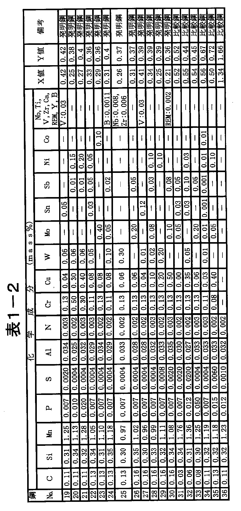
- X value (1 ⁇ 0.8 ⁇ Cu 0.5 ) ⁇ ⁇ 1 ⁇ (0.8 ⁇ W + 0.4 ⁇ Mo) 0.3 ⁇ ⁇ ⁇ 1 ⁇ (0.8 ⁇ Sn + 0.8 ⁇ Sb) 0 .5 ⁇ ⁇ ⁇ 1- (0.05 ⁇ Cr + 0.03 ⁇ Ni + 0.03 ⁇ Co) 0.3 ⁇ ⁇ (1 + S / 0.01 + P / 0.05)
- Y value (1 ⁇ 0.3 ⁇ Cr 0.3 ) ⁇ ⁇ 1 ⁇ (0.8 ⁇ W + 0.5 ⁇ Mo) 0.3 ⁇ ⁇ ⁇ 1 ⁇ (Sn + 0.4 ⁇ Sb) 0.3 ⁇ ⁇ ⁇ 1- (0.1 ⁇ Ni + 0.1 ⁇ Co + 0.05 ⁇ Cu) 0.3 ⁇ ⁇ ⁇ 1+ (
- the above equation (1) is an equation for evaluating the influence of each component on the corrosion in the tanker oil tank, the coefficient of the component improving the corrosion resistance is minus, and the coefficient of the component deteriorating the corrosion resistance. Is represented as plus. Therefore, the steel material having a smaller value of X has better corrosion resistance.
- the inventors have found that if X is 0.5 or less, the corrosion resistance in the corrosive environment in the tanker oil tank is reduced. Although it was excellent, it discovered that the said corrosion resistance was inferior when X exceeded 0.5. Therefore, the steel material of the present invention needs to be designed so that the X value is 0.5 or less. Further preferably, the X value is 0.4 or less.
- the above equation (2) is an equation for evaluating the influence of each component on the corrosion resistance after painting of the ballast tank.
- the coefficient of the component for improving the corrosion resistance is negative, and the corrosion resistance is The coefficient of the component to be deteriorated is expressed as a plus. Therefore, the steel material having a smaller Y value is more excellent in corrosion resistance.
- the inventors have determined that if Y is 0.5 or less, the corrosive environment in the ballast tank Although it was excellent in corrosion resistance after coating, it was found that the corrosion resistance is inferior when Y exceeds 0.5. Therefore, the steel material of the present invention needs to be designed so that the Y value is 0.5 or less. Further, preferably, the Y value is 0.4 or less.
- the steel material of the present invention suppresses pitting corrosion on the tanker tank bottom plate and overall corrosion on the tanker upper deck, and improves corrosion resistance after painting in a corrosive environment that repeats salt water immersion and high humidity like the ballast tank.
- W 0.01 to 1.0 mass%
- Mo 0.01 to 0.5 mass%
- Sn It is preferable to contain one or more selected from 0.001 to 0.2 mass% and Sb: 0.001 to 0.5 mass%, and then one selected from Ni and Co or It is preferable to contain 2 types.
- the steel material of this invention can contain 1 type, or 2 or more types chosen from Nb, Ti, Zr, and V in addition to the said component in the following range.
- Nb 0.001 to 0.1 mass%
- Ti 0.001 to 0.1 mass%
- Zr 0.001 to 0.1 mass%
- V 0.002 to 0.2 mass%
- Nb, Ti, Zr and V are all elements that have an effect of increasing the strength of the steel material, and can be selected and added according to the required strength. In order to acquire the said effect, it is preferable to add Nb, Ti, and Zr 0.001 mass% or more respectively, and V to add 0.002 mass% or more.
- Nb is preferably 0.004 to 0.05 mass%, and more preferably 0.005 to 0.02 mass%.
- Ti is preferably 0.002 to 0.03 mass%, and more preferably 0.002 to 0.01 mass%.
- Zr is preferably 0.001 to 0.05 mass%, and more preferably 0.002 to 0.01 mass%.
- V is preferably 0.003 to 0.15 mass%, and more preferably 0.004 to 0.1 mass%.
- the steel material of the present invention further includes one or more selected from Ca, REM, and Y in the following range in order to increase strength and improve toughness.
- Ca 0.0002 to 0.01 mass%
- REM 0.0002 to 0.015 mass%
- Y 0.0001 to 0.1 mass%
- Ca, REM, and Y are all effective in improving the toughness of the weld heat affected zone, and can be added as necessary.
- the above effect can be obtained by adding Ca: 0.0002 mass% or more, REM: 0.0002 mass% or more, Y: 0.0001 mass% or more, but Ca: 0.01 mass%, REM: 0.015 mass%, Y: If added in excess of 0.1 mass%, the toughness is reduced, so Ca, REM, and Y are preferably added in the above ranges.
- Ca is preferably 0.001 to 0.005 mass%, and more preferably 0.001 to 0.003 mass%.
- the REM is preferably 0.0005 to 0.015 mass%, and more preferably 0.001 to 0.010 mass%.
- Y is preferably 0.0001 to 0.05 mass%, and more preferably 0.0002 to 0.01 mass%.
- the steel material of this invention can contain B in the following range in addition to the said component.
- B 0.0002 to 0.003 mass%
- B is an element that increases the strength of the steel material, and can be added as necessary. In order to acquire the said effect, adding 0.0002 mass% or more is preferable. However, when it exceeds 0.003 mass%, toughness will fall. Therefore, B is preferably added in the range of 0.0002 to 0.003 mass%. It is preferably 0.0002 to 0.002 mass%, and more preferably 0.0002 to 0.0015 mass%.
- the steel material for a tanker of the present invention manufactured by the above method using a steel material having the above component composition is not only excellent in corrosion resistance in the unpainted state (overall corrosion resistance, local corrosion resistance).
- the steel material for crude oil tanks of the present invention has a coating amount of a primer or the like containing metal Zn or a Zn compound (hereinafter collectively referred to as “zinc primer”) converted to a Zn content of 1.0 g /
- zinc primer metal Zn or a Zn compound
- the average Zn content is 10 g / m 2 or more. More preferably, it is 15 g / m 2 or more.
- the relation between the coating thickness of the zinc primer and the Zn content on the steel surface depends on the Zn content in the zinc primer, but generally covers the entire steel surface if the average coating thickness is 10 ⁇ m or more. Thus, an application amount of at least 1.0 g / m 2 or more can be ensured regardless of the type of zinc primer. From the viewpoint of improving the corrosion resistance, there is no particular upper limit on the thickness of the zinc primer. However, as the coating film becomes thicker, the cutting performance and weldability decrease, so that the cutting and welding operations are performed after applying the zinc primer. In some cases, the thickness of the zinc primer is preferably 100 ⁇ m or less, and more preferably 50 ⁇ m or less.
- Such zinc primer coating may be performed, for example, after a shot blast treatment is performed on the steel surface.
- the steel material for crude oil tank of the present invention has an epoxy coating film applied on the surface of an unpainted steel material or on the steel material surface after the above-described zinc primer coating, by applying an epoxy paint or the like. Can be formed. This makes it possible to further improve local corrosion resistance and overall corrosion resistance compared to the case of conventional marine steel materials, and more particularly for ballast tanks under severe corrosive environments caused by seawater. A suitable post-coating corrosion resistance, for example, an effect of improving the swelling resistance of the coating film is obtained.
- the epoxy coating film is not particularly limited, and various epoxy resins can be used. For example, a modified epoxy resin or a tar epoxy resin can be used.
- the film thickness of the epoxy coating film is not particularly limited, but is preferably 500 ⁇ m or less, more preferably 350 ⁇ m or less from the viewpoint of coating cost and workability, and the required characteristics. Depending on the situation, it can be appropriately selected.
- a mixed gas consisting of 12 vol% CO 2 , 5 vol% O 2 , 0.01 vol% SO 2 , 0.3 vol% H 2 S and the balance N 2 is mixed gas.
- Introduced gas 4 was introduced and the corrosion test tank 2 was filled with supersaturated vapor to reproduce the corrosive environment behind the upper deck of the crude oil tank. Then, 30 ° C. ⁇ 4 hours + 50 ° C. ⁇ 4 hours are added to the corrosion test piece 1 set on the upper and back surfaces of the test tank through a temperature control plate 3 incorporating a heater and a cooling system (cooling system). The temperature change to be cycled is repeatedly applied for 180 days, and dew condensation water is generated on the surface of the test piece 1 to cause the overall corrosion.
- reference numeral 5 denotes an emission gas from the test tank.
- the thickness loss due to corrosion was determined from the mass change before and after the test.
- the value is 36% or less with respect to the value of 36 comparative steels, the overall corrosion resistance is very good ( ⁇ ), when it exceeds 60% and 70% or less, it is good ( ⁇ ), and when it exceeds 70%
- the overall corrosivity was evaluated as poor (x).
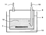
- test pieces were then subjected to a corrosion test immersed in the test solution 12 of the corrosion test apparatus shown in FIG. 2 for one month.
- This corrosion test apparatus is a double type apparatus of a corrosion test tank 8 and a thermostatic tank 9, and a test liquid 12 capable of generating local corrosion similar to that generated in an actual crude oil tank bottom plate is provided in the corrosion test tank 8.
- the test piece 7 is immersed therein.
- artificial seawater specified in ASTM D1141 is used as a test mother water, and the partial pressure ratio of 5 vol% O 2 +10 vol% H 2 S is adjusted in this liquid. It was used after introducing a mixed gas consisting of the balance N 2 gas (incoming gas 10).
- the temperature of the test liquid 12 was maintained at 50 ° C. by adjusting the temperature of the water 13 placed in a constant-temperature bath 9.
- the test solution 12 is constantly stirred because the introduction gas 10 is continuously supplied.
- 11 indicates the exhaust gas from the test tank.
- the corrosion form is visually observed, and the depth of corrosion at the local corrosion occurrence portion is measured with a dip meter. No.
- the local corrosion resistance is very good ( ⁇ ), when it is over 40% and 50% or less, good ( ⁇ ), and when it exceeds 50%
- the local corrosivity was evaluated as poor (x).
- test piece of the above conditions A and B having a coating film an 80 mm length scratch scissor reaching the surface of the iron bar with a cutter knife from the top of the coating film in a single character (in a straight line).
- these test pieces were subjected to a corrosion cycle test simulating the environment of an actual ship's ballast tank (maintained in artificial seawater at a temperature of 30 ° C. for 1 day) ⁇ (relative humidity 98 at a temperature of 40 ° C.). The sample was subjected to a corrosion test that was repeated 60 cycles (120 days).
- Corrosion resistance after coating is very good ( ⁇ ) when it is 50% or less relative to the value of 36 comparative steel, ( ⁇ ) when it is over 50% and 70% or less, and after 70% when it exceeds 70% Corrosion resistance was evaluated as poor (x).
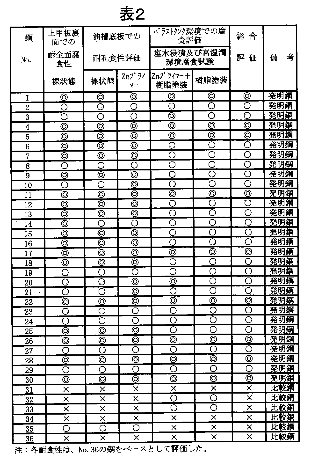
- the corrosion resistance test results (1) to (3) above are shown in Table 2 together with the X value and Y value obtained from the component composition of each steel plate. From Table 2, it is No. which satisfy
- the thick steel plates of 1 to 30 show better corrosion resistance than the target level as a ratio to the base steel material (No. 36) in all the corrosion tests of (1) to (3). No. that does not satisfy the conditions. In any one or more corrosion tests, the thick steel plates 31 to 35 are No. Corrosion exceeding the target level as a ratio to 36 steels has been observed.
- the steel material of the present invention can be suitably used for other ships and crude oil tanks on the ground, in addition to the crude oil tanker.
Landscapes
- Chemical & Material Sciences (AREA)
- Engineering & Computer Science (AREA)
- Materials Engineering (AREA)
- Mechanical Engineering (AREA)
- Metallurgy (AREA)
- Organic Chemistry (AREA)
- Chemical Kinetics & Catalysis (AREA)
- Physics & Mathematics (AREA)
- Thermal Sciences (AREA)
- Crystallography & Structural Chemistry (AREA)
- Heat Treatment Of Steel (AREA)
- Other Surface Treatments For Metallic Materials (AREA)
Abstract
Description
(1)塩化ナトリウム(sodium chloride)を代表とする塩類が高濃度に溶解した凝集水(brine)の存在、
(2)過剰な洗浄による原油保護フィルムの離脱、
(3)原油中に含まれる硫化物(sulfide)の高濃度化、
(4)防爆用のイナートガス中に含まれるO2、CO2、SO2の高濃度化、
(5)微生物(microorganism)の関与、
などが挙げられているが、いずれも推定の域を出ず、明確な原因は判明していない。
しかし、特許文献12および13の技術で何らの考慮もしていないところの、鋼材表面に塗膜が存在する状態における耐食性、いわゆる塗装後耐食性を向上させることは、原油タンカー用耐食鋼材の長寿命化を図る上で極めて有効であり、その技術開発が望まれていたが、現在のところ、これを実現する技術は存在していないのが実情であった。
X値=(1−0.8×Cu0.5)×{1−(0.8×W+0.4×Mo)0.3}×{1−(0.8×Sn+0.8×Sb)0.5}×{1−(0.05×Cr+0.03×Ni+0.03×Co)0.3}×(1+S/0.01+P/0.05) ・・・(1)で定義されるX値が0.5以下、下記(2)式;
Y値=(1−0.3×Cr0.3)×{1−(0.8×W+0.5×Mo)0.3}×{1−(Sn+0.4×Sb)0.3}×{1−(0.1×Ni+0.1×Co+0.05×Cu)0.3}×{1+(S/0.01+P/0.08)0.3} ・・・(2)
で定義されるY値が0.5以下を満たすよう含有し、残部がFeおよび不可避的不純物からなる原油タンカー用耐食鋼材である。ただし、上記各式中の元素記号は、各元素の含有量(mass%)を示す。
C:0.03~0.16mass%
Cは、鋼の強度を高めるのに有効な元素であり、本発明では、所望の強度を確保するために、0.03mass%以上添加する必要がある。一方、0.16mass%を超える添加は、溶接性(weldability)および溶接熱影響部の靭性(toughness)を低下させる。よって、Cは0.03~0.16mass%の範囲で添加する。好適には0.05~0.15mass%であり、さらに好適には0.10~0.15mass%である。
Siは、脱酸剤(deoxidizing agent)として添加する元素であるが、鋼の強度を高める元素でもある。そこで、本発明では、所望の強度を確保するため、0.05mass%以上添加する。しかし、1.50mass%を超える添加は、鋼の靭性を低下させる。よって、Siは0.05~1.50mass%の範囲とする。好適には0.20~1.50mass%であり、さらに好適には0.30~1.20mass%である。
Mnは、鋼の強度を高める元素であり、本発明では、所望の強度を得るため、0.1mass%以上添加する。一方、2.0mass%を超える添加は、靭性および溶接性を低下させる。よって、Mnは0.1~2.0mass%の範囲とする。好適には0.5~1.6mass%であり、さらに好適には0.7~1.5mass%である。
Pは、粒界に偏析して鋼の靭性を低下させる有害な元素であり、できる限り低減するのが望ましい。特に、Pを0.025mass%を超えて含有すると、靭性が大きく低下する。また、Pは0.025mass%を超えて含有すると、耐食性にも悪影響を及ぼす。よって、Pは0.025mass%以下とする。好ましくは0.015mass%以下である。好適には0.010mass%以下であり、さらに好適には0.008mass%以下である。
Sは、非金属介在物(non−metal inclusion)であるMnSを形成して局部腐食の起点となり、耐局部腐食性を低下させる有害な元素であり、できる限り低減するのが望ましい。特に、0.01mass%を超える含有は、耐局部腐食性の顕著な低下を招く。よって、Sの上限は0.01mass%とする。好適には0.005mass%以下であり、さらに好適には0.001mass%以下である。
Alは、脱酸剤として添加する元素であり、本発明では0.005mass%以上添加する必要がある。しかし、0.10mass%を超えて添加すると、鋼の靭性が低下するので、Alの上限は0.10mass%とする。好適には0.01~0.06mass%であり、さらに好適には0.02~0.05mass%である。
Nは、靭性を低下させる有害な元素であり、できる限り低減するのが望ましい。特に、0.008mass%を超えて含有すると、靭性の低下が大きくなるので、上限は0.008mass%とする。好適には0.005mass%以下であり、さらに好適には0.004mass%以下である。
Crは、腐食の進行に伴って錆層中に移行し、Cl−の錆層への侵入を遮断することによって、錆層と地鉄の界面へのCl−の濃縮を抑制する。また、Zn含有プライマーを塗布したときには、Feを中心としたCrやZnの複合酸化物を形成して、長期間にわたり鋼板表面にZnを存続させることができるため、飛躍的に耐食性を向上することができる。特に、上記効果は、タンカー油槽底板部の裏面となるバラストタンクのように、塩分を含む海水と接触する環境での耐食性向上に有効であり、Crを含有した鋼材にZn含有プライマー処理を施すことにより、Crを含有しない鋼材と比較して、格段に耐食性を向上することができる。上記Crの効果は、0.1mass%以下では十分に得られず、一方、0.5mass%を超える添加は、溶接部の靭性を低下させる。よって、Crは0.1mass%超0.5mass%以下の範囲とする。特に良好な溶接部靱性を要求される場合、Cr量は、好適には0.11~0.20mass%であり、さらに好適には0.11~0.16mass%である。
Cuは、鋼の強度を高める元素であるとともに、鋼の腐食によって生成した錆中に存在し、耐食性を高める効果がある。これらの効果は、0.03mass%未満の添加では十分に得られず、一方、0.5mass%を超える添加は、溶接熱影響部の靱性の低下や製造時の表面割れ(surface cracking)などを引き起こすおそれがある。このため、Cuは0.03~0.5mass%の範囲で添加する。好適には0.04~0.20mass%であり、さらに好適には0.04~0.15mass%である。
W:0.01~0.5mass%
Wは、タンカー油槽部底板における孔食を抑制する効果があるほか、タンカー上甲板部の全面腐食に対する耐食性やバラストタンク部のような塩水(salt water)への浸漬と高湿潤(high moistness)を繰り返す腐食環境での塗装後の耐食性を向上させる効果がある。上記効果は、0.01mass%以上の添加で発現する。しかし、0.5mass%を超えると、その効果が飽和してしまう。よって、Wは0.01~0.5mass%の範囲で添加する。好ましくは、0.02~0.3mass%の範囲である。さらに好適には0.03~0.10mass%である。
Moは、タンカー油槽部底板における孔食を抑制するだけでなく、タンカー上甲板部の全面腐食に対する耐食性や、バラストタンクの塩水浸漬と高湿潤を繰り返す腐食環境における塗装後の耐食性をも向上させる効果がある。上記効果は0.01mass%以上の添加で発現するが、0.5mass%を超えると、その効果は飽和してしまう。よって、Moは0.01~0.5mass%の範囲で添加する。好ましくは、0.03~0.4mass%の範囲である。さらに好適には0.03~0.10mass%である。
なお、Moが上記のような耐食性向上効果を有する理由は、Wと同様、鋼板の腐食に伴って生成する錆中にMoO4 2−が生成し、このMoO4 2−の存在によって、塩化物イオンが鋼板表面に侵入するのが抑制される結果、鋼板の腐食が効果的に抑えられるものと考えられる。
SnおよびSbは、タンカー油槽部底板における孔食を抑制する効果を有する他、タンカー上甲板部の全面腐食に対する耐食性やバラストタンクの塩水浸漬と高湿潤を繰り返す腐食環境での塗装後の耐食性をも向上させる効果がある。上記効果は、Sn:0.001mass%以上、Sb:0.001mass%以上の添加で発現する。一方、Sn:0.2mass%超えおよびSb:0.5mass%超え添加しても、その効果は飽和するだけである。よって、Snは0.001~0.2mass%、Sbは0.001~0.5mass%の範囲で添加する。Snについては、好適には0.005~0.10mass%であり、さらに好適には0.01~0.06mass%である。また、Sbについては、好適には0.02~0.15mass%であり、さらに好適には0.03~0.10mass%である。
NiおよびCoは、生成した錆粒子を微細化することによって、裸状態(no−coating)での耐食性およびジンクプライマー塗膜の上にエポキシ系塗装が施された状態での耐食性を少なからず向上する効果を有する。したがって、これらの元素は、耐食性をより向上したい場合に、補助的に含有させるのが好ましい。上記効果は、Ni:0.005mass%以上、Co:0.005mass%以上の添加で発現する。一方、Ni:0.3mass%超え、Co:0.3mass%超え添加しても、その効果が飽和してしまう。よって、NiおよびCoは、それぞれ上記範囲で添加するのが好ましい。Niについては、好適には0.01~0.2mass%であり、さらに好適には0.03~0.15mass%である。また、Coについては、好適には0.01~0.2mass%であり、さらに好適には0.03~0.15mass%である。
X値=(1−0.8×Cu0.5)×{1−(0.8×W+0.4×Mo)0.3}×{1−(0.8×Sn+0.8×Sb)0.5}×{1−(0.05×Cr+0.03×Ni+0.03×Co)0.3}×(1+S/0.01+P/0.05) ・・・(1)
Y値=(1−0.3×Cr0.3)×{1−(0.8×W+0.5×Mo)0.3}×{1−(Sn+0.4×Sb)0.3}×{1−(0.1×Ni+0.1×Co+0.05×Cu)0.3}×{1+(S/0.01+P/0.08)0.3} ・・・(2)
ただし、上記式中の各元素記号は、それらの元素の含有量(mass%)を示す。
Nb:0.001~0.1mass%、Ti:0.001~0.1mass%、Zr:0.001~0.1mass%およびV:0.002~0.2mass%
Nb,Ti,ZrおよびVは、いずれも鋼材強度を高める効果のある元素であり、必要強度に応じて選択して添加することができる。上記効果を得るためには、Nb,Ti,Zrはそれぞれ0.001mass%以上、Vは0.002mass%以上添加することが好ましい。しかし、Nb,Ti,Zrは0.1mass%を超えて、Vは0.2mass%を超えて添加すると、靭性が低下するため、Nb,Ti,Zr,Vは、それぞれ上記範囲で添加するのが好ましい。また、Nbについては、好適には0.004~0.05ass%であり、さらに好適には0.005~0.02mass%である。Tiについては、好適には0.002~0.03mass%であり、さらに好適には0.002~0.01mass%である。Zrについては、好適には0.001~0.05mass%であり、さらに好適には0.002~0.01mass%である。Vについては、好適には0.003~0.15mass%であり、さらに好適には0.004~0.1mass%である。
Ca:0.0002~0.01mass%、REM:0.0002~0.015mass%およびY:0.0001~0.1mass%
Ca,REMおよびYは、いずれも、溶接熱影響部の靭性向上に効果があり、必要に応じて添加することができる。上記効果は、Ca:0.0002mass%以上、REM:0.0002mass%以上、Y:0.0001mass%以上の添加で得られるが、Ca:0.01mass%、REM:0.015mass%、Y:0.1mass%を超えて添加すると、却って靭性の低下を招くので、Ca,REM,Yは、それぞれ上記範囲で添加するのが好ましい。また、Caについては、好適には0.001~0.005mass%であり、さらに好適には0.001~0.003mass%である。REMについては、好適には0.0005~0.015mass%であり、さらに好適には0.001~0.010mass%である。Yについては、好適には0.0001~0.05mass%であり、さらに好適には0.0002~0.01mass%である。
B:0.0002~0.003mass%
Bは、鋼材の強度を高める元素であり、必要に応じて添加することができる。上記効果を得るためには、0.0002mass%以上添加するのが好ましい。しかし、0.003mass%を超えて添加すると、靭性が低下する。よって、Bは0.0002~0.003mass%の範囲で添加するのが好ましい。好適には0.0002~0.002mass%であり、さらに好適には0.0002~0.0015mass%である。
上記の成分組成を有する鋼素材を用いて上記の方法で製造された本発明のタンカー用鋼材は、無塗装の状態における耐食性(耐全面腐食性、耐局部腐食性)に優れているのみならず、塗装後の耐食性にも優れているところに特徴がある。特に、本発明の原油タンク用鋼材は、金属ZnあるいはZn化合物を含むプライマー等の塗料(以下、「ジンクプライマー」と総称する。)の塗布量を、Zn含有量に換算して1.0g/m2以上として、ジンクプライマー塗膜を形成することにより、耐局部腐食性および耐全面腐食性を格段に向上することができる。好ましくは平均Zn含有量に換算して10g/m2以上である。より好ましくは15g/m2以上である。ジンクプライマーの塗膜厚と鋼材表面のZn含有量との関係は、ジンクプライマー中のZn含有率に依存するが、一般的には平均塗装厚にして10μm以上であれば、鋼材表面全体を覆うことができ、ジンクプライマーの種類によらず、少なくとも1.0g/m2以上の塗布量を確保することができる。なお、耐食性を向上させる観点からは、ジンクプライマーの膜厚の上限は特に設けないが、塗膜が厚くなると、切断性や溶接性が低下するので、ジンクプライマ−塗布後に切断や溶接の作業がある場合には、ジンクプライマーの膜厚は100μm以下とするのが好ましく、50μm以下とすることがより好ましい。こうしたジンクプライマー塗装は、たとえば、鋼材表面にショットブラスト処理を施した後に実施すればよい。
また、本発明の原油タンク用鋼材は、無塗装の鋼材表面の上に、あるいは、上述のジンクプライマー塗装後の鋼材表面の上に、エポキシ系塗料等を塗布することにより、エポキシ系塗膜を形成することができる。これにより、従来の船舶用鋼材の場合と比較して、耐局部腐食性および耐全面腐食性をさらに向上させることができるとともに、特に海水による厳しい腐食環境下にあるバラストタンク等に用いて、より好適な塗装後耐食性、例えば、耐塗膜膨れ性が向上する効果が得られる。
ここで、エポキシ系塗膜は、特に限定されるものでなく、各種のエポキシ系樹脂を用いることができる。たとえば、変性エポキシ樹脂、タールエポキシ樹脂などを使用することができる。また、エポキシ系塗膜の膜厚は、特に限定されるものではないが、塗装コストや作業性の観点から500μm以下であることが好ましく、350μm以下であることがより好ましく、要求される特性に応じて、適宜選択することができる。
タンカー上甲板裏面における全面腐食に対する耐食性を評価するため、上記No.1~36の厚鋼板から、幅25mm×長さ48mm×厚さ4mmの矩形の小片を切り出し、その表面にショットブラスト(shotblasting)を施して裸状態の腐食試験片とし、図1に示した腐食試験装置(corrosion test equipment)を用いて全面腐食試験を行った。この腐食試験装置は、腐食試験槽(corrosion test chamber)2と温度制御プレート(temperature−controlled plate)3とから構成されており、腐食試験槽2には温度が40℃に保持された水6が注入されており、また、その水6中には、12vol%CO2、5vol%O2、0.01vol%SO2、0.3vol%H2S、残部N2からなる混合ガス(mixed gas)(導入ガス(introduced gas)4)を導入して腐食試験槽2内を過飽和の水蒸気(supersaturated vapor)で充満し、原油タンク上甲板裏の腐食環境を再現した。そして、この試験槽の上裏面にセットした腐食試験片1に、ヒーター(heater)と冷却装置(cooling system)を内蔵した温度制御プレート3を介して30℃×4時間+50℃×4時間を1サイクルとする温度変化を180日間繰り返して付与し、試験片1の表面に結露水(dew condensation water)を生じさせることにより、全面腐食を起こさせるものである。図1中、5は試験槽からの排出ガス(emission gas)を示す。
タンカー油槽部底板における孔食に対する耐食性を評価するため、(1)の試験で用いたのと同じNo.1~36の鋼板から、幅50mm×長さ50mm×厚さ15mmの正方形の小片を切り出し、その表面にショットブラストを施してから、無機系(inorganic system)ジンクプライマーの塗膜厚を0μm(無塗布)、15~25μmの2レベルに塗り分けた。
次いで、上記4種類の小片の端面および裏面に防食性塗料でマスキング(masking)を施してから、腐食試験の被試験面となる表(オモテ)面(right face)に、実際のタンカーから採取した原油成分を含むスラッジ(sludge)を塗布して腐食試験片(corrosion coupon)とした。この際、被試験面の中央部2mmφの部分に、スラッジに硫黄を50mass%混合した硫黄混合スラッジを塗布し、その他の部分には、スラッジのみを均一に塗布した。この試験片では、硫黄混合スラッジを塗布した部分が腐食の起点となり、局部腐食を促進することから、局部腐食抑制に及ぼす鋼材成分、プライマーおよびそれらの組み合わせの影響をより的確に把握することが可能となる。
バラストタンク環境における塗装後の耐食性を評価するため、(1)の試験で用いたのと同じNo.1~36の鋼板から、幅50mm×長さ150mm×厚さ5mmの試験片を採取し、試験片表面にショットブラスト後、以下の条件A,Bの表面処理を施し、暴露試験片を作製した。
条件A:試験片表面に、ジンクプライマー(約15μm)とタールエポキシ樹脂塗料(約200μm)の2層被膜を形成
条件B:試験片表面に、タールエポキシ樹脂塗料(約200μm)の単層被膜を形成
なお、塗膜を有する上記条件AおよびBの試験片には、塗膜の上からカッターナイフ(utility knife)で地鉄表面まで達する80mm長さのスクラッチ疵(scratch)を一文字状に(in a straight line)付与した。
その後、これらの試験片を、実船のバラストタンクの環境を模擬した腐食サイクル試験(corrosion cycle test)として、(温度30℃の人工海水中に1日間保持)→(温度40℃で相対湿度98~99%の湿潤雰囲気に1日間保持)を1サイクルとして、これを60サイクル(120日間)繰り返す腐食試験に供した。各試験片の耐食性の評価は、塗膜を有する条件AおよびBの試験片については、スクラッチ疵の周囲に発生した塗膜膨れ面積を測定し、その比率がNo.36の比較鋼の値に対して50%以下である場合を塗装後耐食性が非常に良好(◎)、50%超70%以下である場合を良好(○)、70%を超える場合を塗装後耐食性が不良(×)と評価した。
2、8:腐食試験槽
3:温度制御プレート
4、10:導入ガス
5、11:排出ガス
6、13:水
9:恒温槽
12:試験液

Claims (8)
- C:0.03~0.16mass%、Si:0.05~1.50mass%、Mn:0.1~2.0mass%、P:0.025mass%以下、S:0.01mass%以下、Al:0.005~0.10mass%、N:0.008mass%以下、Cr:0.1mass%超0.5mass%以下、Cu:0.03~0.5mass%を含有し、かつ、選択的添加元素としてW:0.01~0.5mass%、Mo:0.01~0.5mass%、Sn:0.001~0.2mass%、Sb:0.001~0.5mass%、Ni:0.005~0.3mass%およびCo:0.005~0.3mass%のうちから選ばれる1種または2種以上を含有し、さらに上記成分が下記(1)式で定義されるX値が0.5以下、下記(2)式で定義されるY値が0.5以下を満たすよう含有し、残部がFeおよび不可避的不純物からなる原油タンカー用耐食鋼材。
記
X値=(1−0.8×Cu0.5)×{1−(0.8×W+0.4×Mo)0.3}×{1−(0.8×Sn+0.8×Sb)0.5}×{1−(0.05×Cr+0.03×Ni+0.03×Co)0.3}×(1+S/0.01+P/0.05) ・・・(1)
Y値=(1−0.3×Cr0.3)×{1−(0.8×W+0.5×Mo)0.3}×{1−(Sn+0.4×Sb)0.3}×{1−(0.1×Ni+0.1×Co+0.05×Cu)0.3}×{1+(S/0.01+P/0.08)0.3} ・・・(2)
ただし、上記式中の元素記号は、各元素の含有量(mass%)を示す。 - 上記選択的添加元素として、W:0.01~0.5mass%、Mo:0.01~0.5mass%、Sn:0.001~0.2mass%およびSb:0.001~0.5mass%のうちから選ばれる1種または2種以上を含有する請求項1に記載の原油タンカー用耐食鋼材。
- 上記選択的添加元素に加えてさらに、Ni:0.005~0.3mass%およびCo:0.005~0.3mass%のうちから選ばれる1種または2種を含有する請求項2に記載の原油タンカー用耐食鋼材。
- 上記成分組成に加えてさらに、Nb:0.001~0.1mass%、Ti:0.001~0.1mass%、Zr:0.001~0.1mass%およびV:0.002~0.2mass%のうちから選ばれる1種または2種以上を含有する請求項1~3のいずれかに記載の原油タンカー用耐食鋼材。
- 上記成分組成に加えてさらに、Ca:0.0002~0.01mass%、REM:0.0002~0.015mass%およびY:0.0001~0.1mass%のうちから選ばれる1種または2種以上を含有する請求項1~4のいずれかに記載の原油タンカー用耐食鋼材。
- 上記成分組成に加えてさらに、B:0.0002~0.003mass%を含有する請求項1~5のいずれかに記載の原油タンカー用耐食鋼材。
- 上記鋼材の表面に、Znを含むプライマー塗膜を形成してなる請求項1~6のいずれかに記載の原油タンカー用耐食鋼材。
- 上記鋼材の表面に、エポキシ系塗膜を形成してなる請求項1~7のいずれかに記載の原油タンカー用耐食鋼材。
Priority Applications (3)
| Application Number | Priority Date | Filing Date | Title |
|---|---|---|---|
| EP09835097.8A EP2377963B1 (en) | 2008-12-24 | 2009-12-22 | Corrosion-resistant steel material for crude oil tanker |
| CN200980152637XA CN102264937B (zh) | 2008-12-24 | 2009-12-22 | 原油轮用耐腐蚀钢材 |
| KR1020107026861A KR101147950B1 (ko) | 2008-12-24 | 2009-12-22 | 원유 탱커용 내식강재 |
Applications Claiming Priority (4)
| Application Number | Priority Date | Filing Date | Title |
|---|---|---|---|
| JP2008327466 | 2008-12-24 | ||
| JP2008-327466 | 2008-12-24 | ||
| JP2009035217 | 2009-02-18 | ||
| JP2009-035217 | 2009-02-18 |
Publications (1)
| Publication Number | Publication Date |
|---|---|
| WO2010074307A1 true WO2010074307A1 (ja) | 2010-07-01 |
Family
ID=42287900
Family Applications (1)
| Application Number | Title | Priority Date | Filing Date |
|---|---|---|---|
| PCT/JP2009/071841 Ceased WO2010074307A1 (ja) | 2008-12-24 | 2009-12-22 | 原油タンカー用耐食鋼材 |
Country Status (6)
| Country | Link |
|---|---|
| EP (1) | EP2377963B1 (ja) |
| JP (1) | JP4502075B1 (ja) |
| KR (2) | KR101147950B1 (ja) |
| CN (1) | CN102264937B (ja) |
| TW (1) | TWI404807B (ja) |
| WO (1) | WO2010074307A1 (ja) |
Cited By (8)
| Publication number | Priority date | Publication date | Assignee | Title |
|---|---|---|---|---|
| WO2011145739A1 (ja) * | 2010-05-18 | 2011-11-24 | Jfeスチール株式会社 | 耐食性に優れる溶接継手および原油タンク |
| WO2011145740A1 (ja) * | 2010-05-18 | 2011-11-24 | Jfeスチール株式会社 | 耐食性に優れる溶接継手および原油タンク |
| WO2011145741A1 (ja) * | 2010-05-18 | 2011-11-24 | Jfeスチール株式会社 | 耐食性に優れる溶接継手および原油タンク |
| CN102899570A (zh) * | 2011-07-27 | 2013-01-30 | 株式会社神户制钢所 | 耐腐蚀性优异的油轮的罐顶用或散装货船的船舱用钢材 |
| CN102927433A (zh) * | 2012-11-09 | 2013-02-13 | 无锡电站辅机厂 | 压缩空气储罐 |
| CN104596915A (zh) * | 2015-01-30 | 2015-05-06 | 钢铁研究总院青岛海洋腐蚀研究所 | 一种货油舱上甲板模拟腐蚀试验用反应釜及其使用方法 |
| WO2015087531A1 (ja) * | 2013-12-12 | 2015-06-18 | Jfeスチール株式会社 | 原油タンク用鋼材および原油タンク |
| WO2015087532A1 (ja) * | 2013-12-12 | 2015-06-18 | Jfeスチール株式会社 | 原油タンク用鋼材および原油タンク |
Families Citing this family (32)
| Publication number | Priority date | Publication date | Assignee | Title |
|---|---|---|---|---|
| CN102301025B (zh) * | 2009-01-30 | 2014-06-25 | 杰富意钢铁株式会社 | 原油罐用耐腐蚀钢材及其制造方法以及原油罐 |
| JP5702683B2 (ja) * | 2011-07-29 | 2015-04-15 | 株式会社神戸製鋼所 | ばら積貨物船用耐食鋼材およびばら積貨物船の船倉 |
| CN102534421B (zh) * | 2012-01-19 | 2013-09-11 | 宁波市瑞通新材料科技有限公司 | 一种天然气输送管道用耐腐蚀钢 |
| CN102534422B (zh) * | 2012-01-19 | 2013-09-11 | 宁波市瑞通新材料科技有限公司 | 一种天然气输送管道用耐腐蚀钢管的制备方法 |
| JP5869918B2 (ja) * | 2012-03-07 | 2016-02-24 | 株式会社神戸製鋼所 | 耐水素吸収性に優れた硫化水素環境用鋼材および鋼構造物 |
| JP2014019908A (ja) * | 2012-07-18 | 2014-02-03 | Nippon Steel & Sumitomo Metal | 防食被覆鋼材 |
| CN103045969B (zh) * | 2012-12-25 | 2015-10-28 | 钢铁研究总院 | 一种免涂装的耐腐蚀钢材 |
| CN103667892B (zh) * | 2013-11-29 | 2016-04-13 | 国家电网公司 | 一种耐酸性土壤腐蚀耐磨的接地网合金材料 |
| CN104195461A (zh) * | 2014-09-10 | 2014-12-10 | 首钢总公司 | 可同时满足原油油船货油舱上甲板、内底板用耐腐蚀钢 |
| CN104404395B (zh) * | 2014-11-11 | 2016-09-28 | 南京钢铁股份有限公司 | 油船货油舱用耐蚀球扁钢及其冶炼工艺 |
| CN106435406B (zh) * | 2015-08-13 | 2019-02-05 | 上海梅山钢铁股份有限公司 | 一种厚规格低合金耐候钢板及其制造方法 |
| CN106676415B (zh) * | 2015-11-06 | 2019-03-15 | 攀钢集团攀枝花钢铁研究院有限公司 | 含铬氮耐大气腐蚀型钢钢水和耐大气腐蚀型钢及其生产方法 |
| CN105349911A (zh) * | 2015-12-02 | 2016-02-24 | 南京钢铁股份有限公司 | 一种低成本无Nb薄规格耐硫酸露点腐蚀钢及其生产方法 |
| JP2017190522A (ja) * | 2016-04-11 | 2017-10-19 | Jfeスチール株式会社 | 鋼材 |
| CN105970086B (zh) * | 2016-06-29 | 2018-04-20 | 巢湖鹏远金属焊管有限公司 | 高强度耐腐蚀直缝焊管用钢 |
| WO2018038197A1 (ja) * | 2016-08-25 | 2018-03-01 | Jfeスチール株式会社 | 耐硫酸露点腐食鋼 |
| JP6260755B1 (ja) * | 2016-10-06 | 2018-01-17 | Jfeスチール株式会社 | 船舶バラストタンク用鋼材および船舶 |
| CN106521348A (zh) * | 2016-12-09 | 2017-03-22 | 苏州陈恒织造有限公司 | 一种抗腐蚀耐磨损型纺织机用缓冲结构 |
| CN106590077A (zh) * | 2016-12-15 | 2017-04-26 | 苏州富艾姆工业设备有限公司 | 一种抗腐蚀耐磨损型水泵活塞的处理工艺 |
| KR101879082B1 (ko) * | 2016-12-21 | 2018-07-16 | 주식회사 포스코 | 저항복비형 초고강도 강재 및 그 제조방법 |
| JP6536769B1 (ja) * | 2017-11-24 | 2019-07-03 | Jfeスチール株式会社 | 原油タンカー上甲板および底板用耐食鋼材、ならびに、原油タンカー |
| CN111655887A (zh) * | 2018-01-26 | 2020-09-11 | 日本制铁株式会社 | 锚链用钢和锚链 |
| CN108300944A (zh) * | 2018-04-13 | 2018-07-20 | 合肥市旺友门窗有限公司 | 一种减振降噪不锈钢管材及其制备方法 |
| CN109136741B (zh) * | 2018-07-12 | 2020-12-04 | 贵州捷盛钻具股份有限公司 | 一种耐腐蚀圆钢及其制备方法与应用 |
| CN109652736B (zh) * | 2018-12-27 | 2020-04-24 | 钢铁研究总院 | 一种油轮用免涂层耐蚀型钢 |
| CN109628844B (zh) * | 2019-02-12 | 2020-05-29 | 鞍钢股份有限公司 | 屈服强度700MPa级运煤敞车用耐蚀钢及其制造方法 |
| CN109628842B (zh) * | 2019-02-12 | 2020-05-29 | 鞍钢股份有限公司 | 屈服强度550MPa级运煤敞车用耐蚀钢及其制造方法 |
| CN109628841B (zh) * | 2019-02-12 | 2020-05-29 | 鞍钢股份有限公司 | 屈服强度350MPa级运煤敞车用耐蚀钢及其制造方法 |
| CN109628843B (zh) * | 2019-02-12 | 2020-05-29 | 鞍钢股份有限公司 | 屈服强度450MPa级运煤敞车用耐蚀钢及其制造方法 |
| CN111485173B (zh) * | 2020-04-09 | 2020-12-08 | 广东德纳斯金属制品有限公司 | 一种新型恒温材料及其制备方法和应用 |
| CN112680675A (zh) * | 2020-12-08 | 2021-04-20 | 莱芜钢铁集团淄博锚链有限公司 | 一种含硼钢及其制备方法 |
| CN113549822B (zh) * | 2021-06-29 | 2022-06-14 | 鞍钢股份有限公司 | 一种耐海洋大气腐蚀用高性能钢板及其生产方法 |
Citations (18)
| Publication number | Priority date | Publication date | Assignee | Title |
|---|---|---|---|---|
| JPS4850922A (ja) | 1971-11-01 | 1973-07-18 | ||
| JPS4850924A (ja) | 1971-11-01 | 1973-07-18 | ||
| JPS4850921A (ja) | 1971-11-01 | 1973-07-18 | ||
| JPS5974219A (ja) * | 1982-10-19 | 1984-04-26 | Kawasaki Steel Corp | 石油貯槽用厚鋼板の製造方法 |
| JPH0734270A (ja) | 1993-07-15 | 1995-02-03 | Sumitomo Metal Ind Ltd | バラストタンクの防食方法 |
| JPH0734197A (ja) | 1993-07-15 | 1995-02-03 | Sumitomo Metal Ind Ltd | 耐久性に優れたバラストタンク |
| JPH0734196A (ja) | 1993-07-15 | 1995-02-03 | Sumitomo Metal Ind Ltd | 耐久性に優れたバラストタンク |
| JPH07310141A (ja) | 1993-07-09 | 1995-11-28 | Kawasaki Steel Corp | 高温多湿環境用耐海水鋼およびその製造方法 |
| JP2000017381A (ja) | 1998-07-03 | 2000-01-18 | Nippon Steel Corp | 造船用耐食鋼 |
| JP2002266052A (ja) | 2001-03-09 | 2002-09-18 | Kawasaki Steel Corp | 塗膜寿命性に優れた船舶用鋼材 |
| JP2003082435A (ja) | 2001-07-04 | 2003-03-19 | Sumitomo Metal Ind Ltd | カーゴオイルタンク用鋼材 |
| WO2004001083A1 (ja) * | 2002-06-19 | 2003-12-31 | Nippon Steel Corporation | 原油油槽用鋼およびその製造方法、原油油槽およびその防食方法 |
| JP2005325439A (ja) | 2004-04-14 | 2005-11-24 | Sumitomo Metal Ind Ltd | カーゴオイルタンク用鋼材 |
| WO2007116593A1 (ja) * | 2006-03-30 | 2007-10-18 | Jfe Steel Corporation | 原油タンク用耐食鋼材および原油タンク |
| JP2007270196A (ja) | 2006-03-30 | 2007-10-18 | Sumitomo Metal Ind Ltd | カーゴオイルタンク用鋼材 |
| JP2007277615A (ja) * | 2006-04-04 | 2007-10-25 | Kobe Steel Ltd | 耐食性に優れた船舶用鋼材 |
| JP2007277616A (ja) * | 2006-04-04 | 2007-10-25 | Kobe Steel Ltd | 耐食性に優れた原油タンク底板用鋼材 |
| JP2009209412A (ja) * | 2008-03-04 | 2009-09-17 | Kobe Steel Ltd | 耐食性に優れた船舶用鋼材 |
Family Cites Families (6)
| Publication number | Priority date | Publication date | Assignee | Title |
|---|---|---|---|---|
| JPH06179910A (ja) * | 1992-12-14 | 1994-06-28 | Sumitomo Metal Ind Ltd | 耐水素誘起割れ性にすぐれた鋼板の製造方法 |
| JP3800928B2 (ja) * | 2000-03-30 | 2006-07-26 | Jfeスチール株式会社 | 高耐食性燃料タンク用鋼板 |
| KR20060048364A (ko) * | 2004-06-29 | 2006-05-18 | 가부시키가이샤 고베 세이코쇼 | 내식성이 우수한 선박용 강재 |
| JP4659626B2 (ja) * | 2006-01-25 | 2011-03-30 | 株式会社神戸製鋼所 | 耐食性と母材靭性に優れた船舶用高張力鋼材 |
| CN101389782B (zh) * | 2006-02-27 | 2011-05-25 | 杰富意钢铁株式会社 | 船舶用耐腐蚀钢材 |
| JP4898543B2 (ja) * | 2007-05-02 | 2012-03-14 | 株式会社神戸製鋼所 | 耐ピット性に優れた鋼板およびその製造方法 |
-
2009
- 2009-12-21 JP JP2009288921A patent/JP4502075B1/ja active Active
- 2009-12-22 KR KR1020107026861A patent/KR101147950B1/ko not_active Expired - Fee Related
- 2009-12-22 EP EP09835097.8A patent/EP2377963B1/en active Active
- 2009-12-22 CN CN200980152637XA patent/CN102264937B/zh active Active
- 2009-12-22 WO PCT/JP2009/071841 patent/WO2010074307A1/ja not_active Ceased
- 2009-12-22 KR KR1020127000288A patent/KR20120008089A/ko not_active Withdrawn
- 2009-12-23 TW TW098144495A patent/TWI404807B/zh active
Patent Citations (19)
| Publication number | Priority date | Publication date | Assignee | Title |
|---|---|---|---|---|
| JPS4850922A (ja) | 1971-11-01 | 1973-07-18 | ||
| JPS4850924A (ja) | 1971-11-01 | 1973-07-18 | ||
| JPS4850921A (ja) | 1971-11-01 | 1973-07-18 | ||
| JPS5974219A (ja) * | 1982-10-19 | 1984-04-26 | Kawasaki Steel Corp | 石油貯槽用厚鋼板の製造方法 |
| JPH07310141A (ja) | 1993-07-09 | 1995-11-28 | Kawasaki Steel Corp | 高温多湿環境用耐海水鋼およびその製造方法 |
| JPH0734270A (ja) | 1993-07-15 | 1995-02-03 | Sumitomo Metal Ind Ltd | バラストタンクの防食方法 |
| JPH0734197A (ja) | 1993-07-15 | 1995-02-03 | Sumitomo Metal Ind Ltd | 耐久性に優れたバラストタンク |
| JPH0734196A (ja) | 1993-07-15 | 1995-02-03 | Sumitomo Metal Ind Ltd | 耐久性に優れたバラストタンク |
| JP2000017381A (ja) | 1998-07-03 | 2000-01-18 | Nippon Steel Corp | 造船用耐食鋼 |
| JP2002266052A (ja) | 2001-03-09 | 2002-09-18 | Kawasaki Steel Corp | 塗膜寿命性に優れた船舶用鋼材 |
| JP2003082435A (ja) | 2001-07-04 | 2003-03-19 | Sumitomo Metal Ind Ltd | カーゴオイルタンク用鋼材 |
| WO2004001083A1 (ja) * | 2002-06-19 | 2003-12-31 | Nippon Steel Corporation | 原油油槽用鋼およびその製造方法、原油油槽およびその防食方法 |
| JP2004204344A (ja) | 2002-06-19 | 2004-07-22 | Nippon Steel Corp | 原油油槽用鋼およびその製造方法、原油油槽およびその防食方法 |
| JP2005325439A (ja) | 2004-04-14 | 2005-11-24 | Sumitomo Metal Ind Ltd | カーゴオイルタンク用鋼材 |
| WO2007116593A1 (ja) * | 2006-03-30 | 2007-10-18 | Jfe Steel Corporation | 原油タンク用耐食鋼材および原油タンク |
| JP2007270196A (ja) | 2006-03-30 | 2007-10-18 | Sumitomo Metal Ind Ltd | カーゴオイルタンク用鋼材 |
| JP2007277615A (ja) * | 2006-04-04 | 2007-10-25 | Kobe Steel Ltd | 耐食性に優れた船舶用鋼材 |
| JP2007277616A (ja) * | 2006-04-04 | 2007-10-25 | Kobe Steel Ltd | 耐食性に優れた原油タンク底板用鋼材 |
| JP2009209412A (ja) * | 2008-03-04 | 2009-09-17 | Kobe Steel Ltd | 耐食性に優れた船舶用鋼材 |
Cited By (14)
| Publication number | Priority date | Publication date | Assignee | Title |
|---|---|---|---|---|
| CN102892913A (zh) * | 2010-05-18 | 2013-01-23 | 杰富意钢铁株式会社 | 耐腐蚀性优异的焊接接头及原油罐 |
| WO2011145741A1 (ja) * | 2010-05-18 | 2011-11-24 | Jfeスチール株式会社 | 耐食性に優れる溶接継手および原油タンク |
| JP2012001810A (ja) * | 2010-05-18 | 2012-01-05 | Jfe Steel Corp | 耐食性に優れる溶接継手および原油タンク |
| JP2012001809A (ja) * | 2010-05-18 | 2012-01-05 | Jfe Steel Corp | 耐食性に優れる溶接継手および原油タンク |
| JP2012000669A (ja) * | 2010-05-18 | 2012-01-05 | Jfe Steel Corp | 耐食性に優れる溶接継手および原油タンク |
| WO2011145739A1 (ja) * | 2010-05-18 | 2011-11-24 | Jfeスチール株式会社 | 耐食性に優れる溶接継手および原油タンク |
| WO2011145740A1 (ja) * | 2010-05-18 | 2011-11-24 | Jfeスチール株式会社 | 耐食性に優れる溶接継手および原油タンク |
| CN102899570A (zh) * | 2011-07-27 | 2013-01-30 | 株式会社神户制钢所 | 耐腐蚀性优异的油轮的罐顶用或散装货船的船舱用钢材 |
| CN102927433A (zh) * | 2012-11-09 | 2013-02-13 | 无锡电站辅机厂 | 压缩空气储罐 |
| JP2015113507A (ja) * | 2013-12-12 | 2015-06-22 | Jfeスチール株式会社 | 耐食性に優れる原油タンク用鋼材および原油タンク |
| WO2015087531A1 (ja) * | 2013-12-12 | 2015-06-18 | Jfeスチール株式会社 | 原油タンク用鋼材および原油タンク |
| WO2015087532A1 (ja) * | 2013-12-12 | 2015-06-18 | Jfeスチール株式会社 | 原油タンク用鋼材および原油タンク |
| JPWO2015087531A1 (ja) * | 2013-12-12 | 2017-03-16 | Jfeスチール株式会社 | 原油タンク用鋼材および原油タンク |
| CN104596915A (zh) * | 2015-01-30 | 2015-05-06 | 钢铁研究总院青岛海洋腐蚀研究所 | 一种货油舱上甲板模拟腐蚀试验用反应釜及其使用方法 |
Also Published As
| Publication number | Publication date |
|---|---|
| JP4502075B1 (ja) | 2010-07-14 |
| KR101147950B1 (ko) | 2012-05-24 |
| TWI404807B (zh) | 2013-08-11 |
| TW201035333A (en) | 2010-10-01 |
| KR20120008089A (ko) | 2012-01-25 |
| CN102264937B (zh) | 2013-10-30 |
| CN102264937A (zh) | 2011-11-30 |
| KR20100137017A (ko) | 2010-12-29 |
| EP2377963A4 (en) | 2015-08-05 |
| EP2377963A1 (en) | 2011-10-19 |
| EP2377963B1 (en) | 2019-03-13 |
| JP2010216005A (ja) | 2010-09-30 |
Similar Documents
| Publication | Publication Date | Title |
|---|---|---|
| JP4502075B1 (ja) | 原油タンカー用耐食鋼材 | |
| CN101389782B (zh) | 船舶用耐腐蚀钢材 | |
| JP4525687B2 (ja) | 船舶用耐食鋼材 | |
| JP5453840B2 (ja) | 耐食性に優れた船舶用鋼材 | |
| JP5662894B2 (ja) | 耐食性に優れた原油タンカーのタンク上甲板用またはバラ積み船の船倉用鋼材 | |
| JP4525686B2 (ja) | 原油タンク用耐食鋼材および原油タンク | |
| JP6048385B2 (ja) | 耐食性に優れる原油タンク用鋼材および原油タンク | |
| WO2011145740A1 (ja) | 耐食性に優れる溶接継手および原油タンク | |
| JP5526859B2 (ja) | 原油タンカー用鋼材 | |
| JP4577158B2 (ja) | 原油タンク用耐食鋼材 | |
| JP5058574B2 (ja) | 電気防食される船舶バラストタンク用防錆鋼板および船舶バラストタンクの防錆方法 | |
| CN105745347B (zh) | 原油罐用钢材和原油罐 | |
| WO2011145739A1 (ja) | 耐食性に優れる溶接継手および原油タンク | |
| JP2014201759A (ja) | 耐食性に優れる原油タンク用鋼材および原油タンク | |
| JP2014201758A (ja) | 耐食性に優れる原油タンク用鋼材および原油タンク | |
| JP5216199B2 (ja) | 耐すきま腐食性に優れた船舶用溶接継手および溶接構造体 | |
| JP4923614B2 (ja) | 船舶用耐食鋼材 | |
| JP2012117138A (ja) | 耐食性に優れる原油タンク用鋼材、溶接継手および原油タンク | |
| JP5629279B2 (ja) | 耐食性に優れた溶接継手および溶接構造体 | |
| JP6409962B2 (ja) | 耐食性に優れる原油タンク用鋼材および原油タンク | |
| JP6201376B2 (ja) | 耐食性に優れる原油タンク用鋼材および原油タンク | |
| JP2014201756A (ja) | 耐食性に優れる原油タンク用鋼材および原油タンク | |
| JP2007197763A (ja) | 耐食性および靭性に優れた船舶用鋼材 | |
| JP2012117139A (ja) | 耐食性に優れる原油タンク用鋼材、溶接継手および原油タンク |
Legal Events
| Date | Code | Title | Description |
|---|---|---|---|
| WWE | Wipo information: entry into national phase |
Ref document number: 200980152637.X Country of ref document: CN |
|
| 121 | Ep: the epo has been informed by wipo that ep was designated in this application |
Ref document number: 09835097 Country of ref document: EP Kind code of ref document: A1 |
|
| ENP | Entry into the national phase |
Ref document number: 20107026861 Country of ref document: KR Kind code of ref document: A |
|
| WWE | Wipo information: entry into national phase |
Ref document number: 12011501018 Country of ref document: PH |
|
| WWE | Wipo information: entry into national phase |
Ref document number: 2009835097 Country of ref document: EP |
|
| NENP | Non-entry into the national phase |
Ref country code: DE |