WO2010079726A1 - アンモニア合成方法 - Google Patents
アンモニア合成方法 Download PDFInfo
- Publication number
- WO2010079726A1 WO2010079726A1 PCT/JP2009/071843 JP2009071843W WO2010079726A1 WO 2010079726 A1 WO2010079726 A1 WO 2010079726A1 JP 2009071843 W JP2009071843 W JP 2009071843W WO 2010079726 A1 WO2010079726 A1 WO 2010079726A1
- Authority
- WO
- WIPO (PCT)
- Prior art keywords
- water
- oxygen
- ammonia
- hydrogen
- water splitting
- Prior art date
- Legal status (The legal status is an assumption and is not a legal conclusion. Google has not performed a legal analysis and makes no representation as to the accuracy of the status listed.)
- Ceased
Links
Images





Classifications
-
- C—CHEMISTRY; METALLURGY
- C01—INORGANIC CHEMISTRY
- C01B—NON-METALLIC ELEMENTS; COMPOUNDS THEREOF; METALLOIDS OR COMPOUNDS THEREOF NOT COVERED BY SUBCLASS C01C
- C01B3/00—Hydrogen; Gaseous mixtures containing hydrogen; Separation of hydrogen from mixtures containing it; Purification of hydrogen; Reversible storage of hydrogen
- C01B3/02—Production of hydrogen; Production of gaseous mixtures containing hydrogen
- C01B3/04—Production of hydrogen; Production of gaseous mixtures containing hydrogen by decomposition of inorganic compounds
- C01B3/042—Decomposition of water
-
- C—CHEMISTRY; METALLURGY
- C01—INORGANIC CHEMISTRY
- C01B—NON-METALLIC ELEMENTS; COMPOUNDS THEREOF; METALLOIDS OR COMPOUNDS THEREOF NOT COVERED BY SUBCLASS C01C
- C01B13/00—Oxygen; Ozone; Oxides or hydroxides in general
- C01B13/02—Preparation of oxygen
- C01B13/0203—Preparation of oxygen from inorganic compounds
- C01B13/0207—Water
-
- C—CHEMISTRY; METALLURGY
- C01—INORGANIC CHEMISTRY
- C01B—NON-METALLIC ELEMENTS; COMPOUNDS THEREOF; METALLOIDS OR COMPOUNDS THEREOF NOT COVERED BY SUBCLASS C01C
- C01B13/00—Oxygen; Ozone; Oxides or hydroxides in general
- C01B13/02—Preparation of oxygen
- C01B13/0229—Purification or separation processes
- C01B13/0248—Physical processing only
- C01B13/0251—Physical processing only by making use of membranes
-
- C—CHEMISTRY; METALLURGY
- C01—INORGANIC CHEMISTRY
- C01B—NON-METALLIC ELEMENTS; COMPOUNDS THEREOF; METALLOIDS OR COMPOUNDS THEREOF NOT COVERED BY SUBCLASS C01C
- C01B13/00—Oxygen; Ozone; Oxides or hydroxides in general
- C01B13/02—Preparation of oxygen
- C01B13/0229—Purification or separation processes
- C01B13/0248—Physical processing only
- C01B13/0259—Physical processing only by adsorption on solids
- C01B13/0281—Physical processing only by adsorption on solids in getters
-
- C—CHEMISTRY; METALLURGY
- C01—INORGANIC CHEMISTRY
- C01B—NON-METALLIC ELEMENTS; COMPOUNDS THEREOF; METALLOIDS OR COMPOUNDS THEREOF NOT COVERED BY SUBCLASS C01C
- C01B3/00—Hydrogen; Gaseous mixtures containing hydrogen; Separation of hydrogen from mixtures containing it; Purification of hydrogen; Reversible storage of hydrogen
- C01B3/02—Production of hydrogen; Production of gaseous mixtures containing hydrogen
- C01B3/025—Preparation or purification of gas mixtures for ammonia synthesis
-
- C—CHEMISTRY; METALLURGY
- C01—INORGANIC CHEMISTRY
- C01B—NON-METALLIC ELEMENTS; COMPOUNDS THEREOF; METALLOIDS OR COMPOUNDS THEREOF NOT COVERED BY SUBCLASS C01C
- C01B3/00—Hydrogen; Gaseous mixtures containing hydrogen; Separation of hydrogen from mixtures containing it; Purification of hydrogen; Reversible storage of hydrogen
- C01B3/02—Production of hydrogen; Production of gaseous mixtures containing hydrogen
- C01B3/06—Production of hydrogen; Production of gaseous mixtures containing hydrogen by reaction of inorganic compounds containing electro-positively bound hydrogen with inorganic reducing agents
- C01B3/061—Production of hydrogen; Production of gaseous mixtures containing hydrogen by reaction of inorganic compounds containing electro-positively bound hydrogen with inorganic reducing agents by reaction of water with metal oxides
-
- C—CHEMISTRY; METALLURGY
- C01—INORGANIC CHEMISTRY
- C01B—NON-METALLIC ELEMENTS; COMPOUNDS THEREOF; METALLOIDS OR COMPOUNDS THEREOF NOT COVERED BY SUBCLASS C01C
- C01B3/00—Hydrogen; Gaseous mixtures containing hydrogen; Separation of hydrogen from mixtures containing it; Purification of hydrogen; Reversible storage of hydrogen
- C01B3/02—Production of hydrogen; Production of gaseous mixtures containing hydrogen
- C01B3/06—Production of hydrogen; Production of gaseous mixtures containing hydrogen by reaction of inorganic compounds containing electro-positively bound hydrogen with inorganic reducing agents
- C01B3/061—Production of hydrogen; Production of gaseous mixtures containing hydrogen by reaction of inorganic compounds containing electro-positively bound hydrogen with inorganic reducing agents by reaction of water with metal oxides
- C01B3/063—Cyclic methods
-
- C—CHEMISTRY; METALLURGY
- C01—INORGANIC CHEMISTRY
- C01B—NON-METALLIC ELEMENTS; COMPOUNDS THEREOF; METALLOIDS OR COMPOUNDS THEREOF NOT COVERED BY SUBCLASS C01C
- C01B3/00—Hydrogen; Gaseous mixtures containing hydrogen; Separation of hydrogen from mixtures containing it; Purification of hydrogen; Reversible storage of hydrogen
- C01B3/50—Separation of hydrogen or hydrogen-containing gases from gaseous mixtures, e.g. purification
- C01B3/501—Separation of hydrogen or hydrogen-containing gases from gaseous mixtures, e.g. purification by diffusion
-
- C—CHEMISTRY; METALLURGY
- C01—INORGANIC CHEMISTRY
- C01B—NON-METALLIC ELEMENTS; COMPOUNDS THEREOF; METALLOIDS OR COMPOUNDS THEREOF NOT COVERED BY SUBCLASS C01C
- C01B3/00—Hydrogen; Gaseous mixtures containing hydrogen; Separation of hydrogen from mixtures containing it; Purification of hydrogen; Reversible storage of hydrogen
- C01B3/50—Separation of hydrogen or hydrogen-containing gases from gaseous mixtures, e.g. purification
- C01B3/56—Separation of hydrogen or hydrogen-containing gases from gaseous mixtures, e.g. purification by contacting with solids; Regeneration of used solids
-
- C—CHEMISTRY; METALLURGY
- C01—INORGANIC CHEMISTRY
- C01B—NON-METALLIC ELEMENTS; COMPOUNDS THEREOF; METALLOIDS OR COMPOUNDS THEREOF NOT COVERED BY SUBCLASS C01C
- C01B5/00—Water
-
- C—CHEMISTRY; METALLURGY
- C01—INORGANIC CHEMISTRY
- C01C—AMMONIA; CYANOGEN; COMPOUNDS THEREOF
- C01C1/00—Ammonia; Compounds thereof
- C01C1/02—Preparation, purification or separation of ammonia
- C01C1/04—Preparation of ammonia by synthesis
- C01C1/0405—Preparation of ammonia by synthesis from N2 and H2 in presence of a catalyst
-
- B—PERFORMING OPERATIONS; TRANSPORTING
- B01—PHYSICAL OR CHEMICAL PROCESSES OR APPARATUS IN GENERAL
- B01J—CHEMICAL OR PHYSICAL PROCESSES, e.g. CATALYSIS OR COLLOID CHEMISTRY; THEIR RELEVANT APPARATUS
- B01J35/00—Catalysts, in general, characterised by their form or physical properties
- B01J35/30—Catalysts, in general, characterised by their form or physical properties characterised by their physical properties
- B01J35/39—Photocatalytic properties
-
- C—CHEMISTRY; METALLURGY
- C01—INORGANIC CHEMISTRY
- C01B—NON-METALLIC ELEMENTS; COMPOUNDS THEREOF; METALLOIDS OR COMPOUNDS THEREOF NOT COVERED BY SUBCLASS C01C
- C01B2203/00—Integrated processes for the production of hydrogen or synthesis gas
- C01B2203/04—Integrated processes for the production of hydrogen or synthesis gas containing a purification step for the hydrogen or the synthesis gas
- C01B2203/042—Purification by adsorption on solids
-
- C—CHEMISTRY; METALLURGY
- C01—INORGANIC CHEMISTRY
- C01B—NON-METALLIC ELEMENTS; COMPOUNDS THEREOF; METALLOIDS OR COMPOUNDS THEREOF NOT COVERED BY SUBCLASS C01C
- C01B2203/00—Integrated processes for the production of hydrogen or synthesis gas
- C01B2203/06—Integration with other chemical processes
- C01B2203/068—Ammonia synthesis
-
- C—CHEMISTRY; METALLURGY
- C01—INORGANIC CHEMISTRY
- C01B—NON-METALLIC ELEMENTS; COMPOUNDS THEREOF; METALLOIDS OR COMPOUNDS THEREOF NOT COVERED BY SUBCLASS C01C
- C01B2210/00—Purification or separation of specific gases
- C01B2210/0043—Impurity removed
- C01B2210/0053—Hydrogen
-
- Y—GENERAL TAGGING OF NEW TECHNOLOGICAL DEVELOPMENTS; GENERAL TAGGING OF CROSS-SECTIONAL TECHNOLOGIES SPANNING OVER SEVERAL SECTIONS OF THE IPC; TECHNICAL SUBJECTS COVERED BY FORMER USPC CROSS-REFERENCE ART COLLECTIONS [XRACs] AND DIGESTS
- Y02—TECHNOLOGIES OR APPLICATIONS FOR MITIGATION OR ADAPTATION AGAINST CLIMATE CHANGE
- Y02E—REDUCTION OF GREENHOUSE GAS [GHG] EMISSIONS, RELATED TO ENERGY GENERATION, TRANSMISSION OR DISTRIBUTION
- Y02E60/00—Enabling technologies; Technologies with a potential or indirect contribution to GHG emissions mitigation
- Y02E60/30—Hydrogen technology
- Y02E60/36—Hydrogen production from non-carbon containing sources, e.g. by water electrolysis
-
- Y—GENERAL TAGGING OF NEW TECHNOLOGICAL DEVELOPMENTS; GENERAL TAGGING OF CROSS-SECTIONAL TECHNOLOGIES SPANNING OVER SEVERAL SECTIONS OF THE IPC; TECHNICAL SUBJECTS COVERED BY FORMER USPC CROSS-REFERENCE ART COLLECTIONS [XRACs] AND DIGESTS
- Y02—TECHNOLOGIES OR APPLICATIONS FOR MITIGATION OR ADAPTATION AGAINST CLIMATE CHANGE
- Y02P—CLIMATE CHANGE MITIGATION TECHNOLOGIES IN THE PRODUCTION OR PROCESSING OF GOODS
- Y02P20/00—Technologies relating to chemical industry
- Y02P20/10—Process efficiency
- Y02P20/133—Renewable energy sources, e.g. sunlight
-
- Y—GENERAL TAGGING OF NEW TECHNOLOGICAL DEVELOPMENTS; GENERAL TAGGING OF CROSS-SECTIONAL TECHNOLOGIES SPANNING OVER SEVERAL SECTIONS OF THE IPC; TECHNICAL SUBJECTS COVERED BY FORMER USPC CROSS-REFERENCE ART COLLECTIONS [XRACs] AND DIGESTS
- Y02—TECHNOLOGIES OR APPLICATIONS FOR MITIGATION OR ADAPTATION AGAINST CLIMATE CHANGE
- Y02P—CLIMATE CHANGE MITIGATION TECHNOLOGIES IN THE PRODUCTION OR PROCESSING OF GOODS
- Y02P20/00—Technologies relating to chemical industry
- Y02P20/50—Improvements relating to the production of bulk chemicals
- Y02P20/52—Improvements relating to the production of bulk chemicals using catalysts, e.g. selective catalysts
Definitions
- the present invention relates to an ammonia synthesis method for synthesizing ammonia using a reaction between hydrogen and nitrogen.
- the catalyst layer is divided into three parts, and the reaction gas is heat-exchanged between the divided catalyst layers to perform intercooling, whereby the equilibrium theory is obtained.
- the equilibrium theory is obtained.
- Hydrogen for the synthesis of ammonia has been conventionally obtained using natural gas mainly composed of methane (CH 4 ).
- natural gas mainly composed of methane CH 4
- the warming coefficient of methane when the warming coefficient of carbon dioxide is 1 is 23, when natural gas leaks during the collection and use of natural gas mainly composed of methane, Unfavorable impact on global warming.
- the depletion of fossil fuels such as natural gas is realistic.
- the use of natural gas is essentially accompanied by the release of carbon dioxide as a combustion gas, which has an unfavorable effect on global warming. Therefore, it has also been proposed to obtain hydrogen for the synthesis of ammonia by electrolysis of water.
- Patent Document 2 regarding the use of a ruthenium-containing catalyst for the synthesis of ammonia from hydrogen and nitrogen and the production of hydrogen for ammonia synthesis by electrolysis of water, the ruthenium-containing catalyst is covered with water, carbon monoxide, oxygen, or the like.
- the purification of hydrogen and nitrogen used as raw materials in ammonia synthesis is described.
- the ruthenium-containing catalyst is poisoned by a trace amount of oxygen of 1 ppm or more, a trace amount of water of 30 ppm or more, and a trace amount of carbon monoxide.
- Patent Document 2 in order to purify hydrogen and nitrogen as raw materials for ammonia synthesis, in particular, to remove oxygen from hydrogen and nitrogen, a mixed gas of hydrogen and nitrogen is used as a trace amount of oxygen filled with an oxidation catalyst. It has been proposed to circulate through a removal oxidation reactor (catalyst cylinder) where hydrogen and oxygen are reacted to form water.
- a removal oxidation reactor catalyst cylinder
- Patent Document 3 in order to obtain high-purity ammonia used in a light emitting diode (LED) manufacturing process, hydrogen is obtained by electrolysis of water, and this hydrogen is passed through a metal oxide adsorption medium bed. It has been proposed to remove impurities such as H 2 O, CO, CO 2 , O 2 and hydrocarbons.
- the present invention solves the above problems and provides a method for efficiently synthesizing ammonia.
- ⁇ 1> (a) a water splitting step in which water is decomposed to obtain a first source gas containing hydrogen and oxygen; (B) Oxygen contained in the first source gas is at least partially separated and removed by the oxygen separation membrane or the hydrogen separation membrane, and the second source gas having a lower oxygen concentration than the first source gas is obtained. Obtaining a first oxygen removal step; (C) A third source material having a lower oxygen concentration than the second source gas by removing oxygen in the second source gas by reacting with hydrogen and removing it as water or by adsorbing it to an adsorption medium. A second oxygen removal step for obtaining a gas; and (d) an ammonia synthesis step for synthesizing ammonia by reacting hydrogen in the third source gas with nitrogen.
- a method for synthesizing ammonia ⁇ 2> The method according to ⁇ 1> above, wherein in the water decomposition step (a), water is decomposed by a direct thermal decomposition method, a thermochemical decomposition method, or a photocatalytic decomposition method to obtain a first raw material gas.
- a thermochemical decomposition method using a redox reaction between a metal and a metal oxide or a thermochemical decomposition method using a redox reaction between metal oxides having different oxidation states a thermochemical decomposition method using a redox reaction between metal oxides having different oxidation states.
- water decomposition step (a) water is decomposed by a thermochemical decomposition method using an oxidation-reduction reaction between iron oxides having different oxidation states to obtain a first source gas, the item ⁇ 3> the method of. ⁇ 5> The method according to any one of ⁇ 1> to ⁇ 4> above, wherein in the water splitting step (a) and / or the ammonia synthesis step (d), at least a part of the necessary thermal energy is obtained from solar thermal energy. . ⁇ 6> The water splitting step (a) and / or the ammonia synthesizing step (d) are performed in the light collecting unit of the solar light collecting device, and at least a part of the necessary thermal energy is obtained from the solar thermal energy.
- the water decomposition step (a) by a thermochemical decomposition method using a redox reaction between a metal and a metal oxide or a thermochemical decomposition method using a redox reaction between metal oxides having different oxidation states. Decomposing water to obtain a first source gas,
- the water splitting step (a) is performed in a water splitting / regenerating apparatus having a plurality of water splitting units holding the metal and / or metal oxide used in the thermal cracking method, While performing the water splitting step (a) in at least one of the plurality of water splitting units, the used water splitting unit is regenerated in at least one of the plurality of water splitting units.
- the method according to any one of ⁇ 1> to ⁇ 6> above, wherein the regenerated water splitting part is reused in the water splitting step (a).
- oxygen is separated by an oxygen separation membrane or a hydrogen separation membrane, and oxygen and hydrogen are separated.
- water is used as a hydrogen source, it is possible to efficiently synthesize ammonia by using water generation by reaction with hydrogen or adsorption of hydrogen by an adsorption medium.
- FIG. 1 is a diagram showing an example of an ammonia synthesis apparatus used in the ammonia synthesis method of the present invention.
- FIG. 2 is a diagram showing an example of a water splitting / regenerating apparatus used in the ammonia synthesis method of the present invention.
- FIG. 3 is a diagram for explaining the water splitting / regenerating apparatus of FIG. 2.
- FIG. 4 is a diagram showing another example of the water splitting / regenerating apparatus used in the ammonia synthesis method of the present invention.
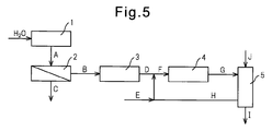
- FIG. 5 is a diagram showing the ammonia synthesis method of Example 1.
- 6 is a diagram showing an ammonia synthesis method of Example 2.
- FIG. 7 is a diagram showing an ammonia synthesis method of Example 3.
- FIG. 8 is a diagram showing the ammonia synthesis method of Example 4.
- FIG. 9 is a diagram showing the ammonia synthesis method of Example 5.
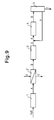
- FIG. 10 is a diagram showing the ammonia synthesis method of Example 6.
- the ammonia synthesis method of the present invention includes at least a water splitting step (a), a first oxygen removing step (b), a second oxygen removing step (c), and an ammonia synthesizing step (d).
- the ammonia synthesis method of the present invention includes a water decomposition step (a), in which water is decomposed to obtain a first source gas containing hydrogen and oxygen.
- thermal energy is required in this process, any source of thermal energy can be used, especially nuclear thermal energy or solar thermal energy, in particular solar thermal energy, in this case global warming This is preferable in that carbon dioxide or the like which is a problem is not released.
- the first raw material gas containing hydrogen and oxygen can be obtained by splitting water in an arbitrary manner.
- the following water splitting method can be used to decompose water in this water splitting step (a):
- the electrolysis method is a method that uses electrolysis of water, can obtain high-purity hydrogen, and is expected to be further improved in terms of running cost and apparatus size.
- Direct thermal decomposition of water is the most basic method for decomposing water to obtain hydrogen and oxygen, and water is directly converted into hydrogen at a high temperature of several thousand degrees Celsius by the reaction shown in the following formula 1. Is a method of breaking down into oxygen: H 2 O ⁇ H 2 + 1 / 2O 2 (several thousand ° C.) (Formula 1)
- This reaction originally requires a temperature of several thousand degrees Celsius, but can be achieved at a temperature of about 2,000 degrees Celsius by using a catalyst.
- hydrogen obtained by the direct pyrolysis method generally contains oxygen.
- thermochemical decomposition method is a method in which water is decomposed at a lower temperature than in the case of direct thermal decomposition by combining chemical reactions.
- Thermochemical decomposition method especially thermochemical decomposition method using redox reaction between metal and metal oxide, or thermochemical decomposition method using redox reaction between metal oxides with different oxidation states, more particularly oxidation state
- thermochemical decomposition method using a redox reaction between different iron oxides can be scaled up and is expected to be put into practical use.
- hydrogen obtained by the thermochemical decomposition method generally contains oxygen.
- As a heat source for the thermochemical decomposition method solar thermal energy or nuclear thermal energy, particularly solar thermal energy can be used.
- thermochemical decomposition method a great number of methods have been proposed. For example, the following methods are considered.
- thermochemical decomposition method-thermochemical decomposition method using oxidation-reduction reaction between metal and metal oxide, or thermochemical decomposition method using oxidation-reduction reaction between metal oxides with different oxidation states A typical example of a thermochemical decomposition method is the following reaction formula, which uses a redox reaction between a metal such as magnesium (Mg), aluminum (Al), iron (Fe) and the metal oxide.
- M is a metal element and m is the valence of the metal element M: M + H 2 O ⁇ M 2 / m 2 O + H 2 (Formula 2) M 2 / m 2 O ⁇ M + 1 / 2O 2 (Formula 3) Total reaction H 2 O ⁇ H 2 + 1 / 2O 2
- thermochemical decomposition method is a method using a redox reaction between iron oxides having different oxidation states in the following reaction formula: 3FeO + H 2 O ⁇ Fe 3 O 4 + H 2 (Formula 4) Fe 3 O 4 ⁇ 3FeO + 1 / 2O 2 (Formula 5) Total reaction H 2 O ⁇ H 2 + 1 / 2O 2
- the metal and / or metal oxide used in this thermochemical decomposition method utilizing the oxidation-reduction reaction of metal and / or metal oxide is supported as fine powder on a carrier of fin type structure, honeycomb type structure, pellet type structure, etc. can do. In this case, it is possible to suppress the sintering of the metal and / or metal oxide used and thereby maintain a relatively large surface area.
- thermochemical decomposition method using a redox reaction of metal and / or metal oxide in particular, the thermochemical decomposition method using zinc is known as a Zn (zinc) method.
- thermochemical decomposition method for example, the following methods (i) to (iii) are considered:
- thermochemical decomposition method-IS iodine-sulfur cycle method
- An IS cycle method represented by the following reaction formula: H 2 SO 4 ⁇ H 2 O + SO 2 + 1 / 2O 2 (About 950 ° C) (Formula 6) 2H 2 O + SO 2 + I 2 ⁇ H 2 SO 4 + 2HI (About 130 ° C) (Formula 7) 2HI ⁇ H 2 + I 2 (about 400 ° C.) (Formula 8) Total reaction H 2 O ⁇ H 2 + 1 / 2O 2
- the photocatalytic decomposition method is a method of decomposing water into hydrogen and oxygen by irradiating light to the photocatalyst in contact with water, and is desirable in terms of producing hydrogen with inexhaustible water and sunlight.
- hydrogen obtained by the photocatalytic decomposition method may contain oxygen.
- the ammonia synthesis method of the present invention includes a first oxygen removal step (b), in which oxygen contained in the first source gas is at least partially separated and removed by an oxygen separation membrane or a hydrogen separation membrane. Thus, a second source gas having an oxygen concentration lower than that of the first source gas is obtained.
- oxygen separation membrane used in the present invention is defined as a membrane that preferentially permeates oxygen over hydrogen when brought into contact with a gas containing at least hydrogen and oxygen.
- the molar ratio (O 2 / H 2 ) between the oxygen permeation amount and the hydrogen permeation amount is, for example, 2 or more, 10 or more, 50 or more, 100 or more, or 1,000 or more at the operating temperature.
- the fraction that has not permeated the oxygen separation membrane has an oxygen concentration higher than that of the first source gas. Dispose of the fraction that has passed through the oxygen separation membrane as a low second source gas, as a fraction containing a relatively large amount of oxygen, recycle, and extract hydrogen, and use for other purposes You can do it.
- oxygen separation membranes are known.
- Japanese Patent Application Laid-Open No. 2008-062188 can be referred to.
- an oxygen separation membrane made of a composite oxide having a mixed conductor of oxygen ions and electrons such as CaTiO 3 can be used.
- the “hydrogen separation membrane” used in the present invention is defined as a membrane that preferentially permeates hydrogen over oxygen when brought into contact with a gas containing at least hydrogen and oxygen.
- the molar ratio (H 2 / O 2 ) between the hydrogen permeation amount and the oxygen permeation amount is, for example, 2 or more, 10 or more, 50 or more, 100 or more, or 1,000 or more at the operating temperature.
- the fraction that has permeated the hydrogen separation membrane has a lower oxygen concentration than the first source gas.
- the fraction that was used as the source gas of 2 and did not permeate the oxygen separation membrane was discarded as a fraction containing a relatively large amount of oxygen, recycled, and further extracted with hydrogen, and used for other purposes. You can do it.
- JP 2008-055295 A can be referred to.
- the ammonia synthesis method of the present invention includes a second oxygen removal step (c), in which oxygen in a second source gas having a lower oxygen concentration than the first source gas is reacted with hydrogen to produce water. Or a third raw material gas having an oxygen concentration lower than that of the second raw material gas.
- an oxidation catalyst can be used to remove oxygen in the second source gas as water by reacting with hydrogen.
- the water produced by the reaction between oxygen and hydrogen is removed by adsorption with zeolite or the like, or by temporarily cooling the raw material gas containing water to 100 ° C. or lower and performing gas-liquid separation. be able to.
- the “oxidation catalyst” used in the present invention is defined as a catalyst that promotes a reaction between hydrogen and oxygen, that is, a reaction in which oxygen oxidizes hydrogen to produce water.
- oxidation catalysts are known, and examples include noble metal-containing catalysts such as platinum-containing catalysts, and base metal-containing catalysts such as cobalt-containing catalysts and nickel-containing catalysts.
- a catalyst is preferred.
- an oxidation catalyst similar to that used in Patent Document 2 that is, a palladium catalyst supported on an alumina carrier, can be considered.
- the adsorption medium used for adsorbing and removing oxygen in the second source gas may include a metal oxide adsorption medium.
- the “adsorption medium” used in the present invention is defined as a medium that preferentially permeates oxygen over hydrogen when brought into contact with a gas containing at least hydrogen and oxygen.
- Many adsorbing media are known. For example, as shown in US Pat. No. 6,241,955, for example, an adsorbing media similar to that used in Patent Document 3 is used.
- the use of metal oxides such as barium, potassium and iron can be considered.
- the ammonia synthesizing method of the present invention includes an ammonia synthesizing step (d), in which hydrogen in a third source gas having a lower oxygen concentration than the second source gas is reacted with nitrogen to synthesize ammonia. .
- Maintaining high temperatures for the synthesis of ammonia from hydrogen and nitrogen can be achieved by any thermal energy source, but in particular by nuclear or solar thermal energy, in particular solar thermal energy, in which case the earth This is preferable in that carbon dioxide and the like, which are problems with respect to global warming, are not released.
- Patent Documents 1 to 3 Synthesis of ammonia from hydrogen and nitrogen is known in many documents, and for example, Patent Documents 1 to 3 can be referred to.
- a catalyst for the synthesis of ammonia a platinum-containing catalyst, a nickel-containing catalyst, and the like can be considered along with the iron-containing catalyst and the ruthenium-containing catalyst.
- nitrogen to be reacted with hydrogen in the step (d) can be added to any of the first to third source gases. That is, for example, nitrogen to be reacted with hydrogen in step (d) is added to the third source gas to reduce the amounts of the first and second source gases processed in the first and second oxygen removal steps, respectively. be able to.
- Nitrogen which is another raw material for the ammonia synthesis method of the present invention, can be obtained by any method.
- it can be obtained by separating air by a cryogenic separation method, a membrane separation method, a pressure swing adsorption method, or the like. Conceivable.
- the cryogenic separation of air the air is compressed while being cooled to form liquid air, and nitrogen is separated from the liquid air by utilizing the difference in boiling point between oxygen and nitrogen. This method generally requires large-scale equipment, but high-purity nitrogen can be obtained.
- the recovery of ammonia produced in the ammonia synthesis step can be performed in any manner, for example, a wet recovery step in which ammonia is absorbed into water and separated from unreacted components hydrogen and nitrogen, or ammonia is liquefied. It can be achieved by a condensation step that separates from unreacted components hydrogen and nitrogen.
- the water splitting step (a) and / or the ammonia synthesizing step (d) is carried out in the light collecting part of the solar light collecting device, and at least part of the necessary thermal energy. Can be obtained from solar thermal energy.
- the water splitting step (a) and / or the ammonia synthesizing step (d) is carried out using ammonia having a water splitting unit and / or an ammonia synthesizing unit arranged in the light collecting unit of the solar light collecting device. It can be implemented in a synthesizer.
- the water splitting part and the ammonia synthesizing part are parts for performing the water splitting process and the ammonia synthesizing process, respectively, of the ammonia synthesizing method of the present invention.
- the solar light collecting device a parabolic dish type light collecting device, a solar tower type light collecting device, a parabolic trough light collecting device, or the like can be used.
- the parabolic dish type condensing device is a condensing device having a dish-like reflecting portion that reflects sunlight and condensing the light and a light receiving portion that receives the condensed light, and has a high degree of condensing and therefore high temperature. A heat source is obtained, but the cost is relatively high.
- the solar tower type condensing device is a condensing device having a plurality of heliostats (reflecting portions) for reflecting sunlight and condensing, and a light receiving portion arranged on the upper portion of the light receiving tower, Therefore, a high-temperature heat source can be obtained, but the construction cost of the tower is high, and the control of the reflector is also required to be highly technical.
- the parabolic trough type condensing device is a condensing device having a trough type reflecting portion for reflecting sunlight and collecting the light and a light receiving portion for receiving the condensed light, and is obtained with a relatively low concentration.
- the heat source is a low temperature heat source.
- the reflecting portion may be covered with a reflective material such as aluminum.
- the ammonia synthesis apparatus used in the ammonia synthesis method of the present invention may be, for example, as shown in FIG.
- a parabolic trough type condensing device 150 having legs 150a is used, and a water splitting unit 101, an oxygen separation membrane ( Alternatively, a hydrogen separation membrane) holding unit 102, an oxidation catalyst (or adsorption medium) holding unit 103, and an ammonia synthesis unit 104 are arranged.
- a water splitting unit 101 an oxygen separation membrane ( Alternatively, a hydrogen separation membrane) holding unit 102, an oxidation catalyst (or adsorption medium) holding unit 103, and an ammonia synthesis unit 104 are arranged.
- the temperature of these portions is high, for example, 500 ° C. or higher, 600 ° C. or higher, or The temperature is maintained at 700 ° C. or higher.
- the ammonia synthesizer 100 can have an optional ammonia recovery unit 105. Further, in the ammonia synthesizer 100, a heat-resistant material conduit such as a nickel-chromium alloy can be used as a conduit connecting the constituent parts. Furthermore, in this ammonia synthesizer 100, the flow path does not need to be linear, and may be meandering to obtain a required flow path length.
- water H 2 O
- the first source gas containing hydrogen and oxygen is decomposed by water.
- the first source gas obtained in the water splitting unit 101 is supplied to the oxygen separation membrane holding unit 102 to separate at least a part of oxygen contained in the first source gas, and this oxygen (O 2 ) is removed.
- a second source gas having a lower oxygen concentration than that of the first source gas is obtained by discharging.
- the second source gas obtained in the oxygen separation membrane holding unit 102 is supplied to the oxidation catalyst holding unit 103, where oxygen in the second source gas is reacted with hydrogen and removed as water (H 2 O).
- a third source gas having a lower oxygen concentration than the second source gas is obtained.
- the third raw material gas obtained in the oxidation catalyst holding unit 103 is supplied to the ammonia synthesis unit 104 as a feed stream together with nitrogen (N 2 ) and a recirculation flow (H 2 + N 2 ), and is supplied with hydrogen and nitrogen. To synthesize ammonia.
- the synthesized ammonia-containing product stream is fed to the ammonia recovery section 105 where ammonia (NH 3 ) is recovered and the remainder is recycled as a recycle stream (H 2 + N 2 ).
- the water decomposition unit 101 after use is switched to the water decomposition unit 101 ′ after the regeneration treatment. By using it, hydrogen can be produced continuously. In this case, the water splitting unit 101 is regenerated while hydrogen is generated using the water splitting unit 101 '.
- thermochemical decomposition method using a redox reaction between a metal and a metal oxide, or between metal oxides having different oxidation states can be obtained by decomposing water by a thermochemical decomposition method using an oxidation-reduction reaction.
- the water splitting step (a) is performed in a water splitting / regenerating apparatus having a plurality of water splitting units holding the metal and / or metal oxide used in the thermal cracking method.
- the used water splitting unit is regenerated and the regenerated water splitting is performed in at least one of the plurality of water splitting units. Can be reused in the water splitting step (a).
- the water decomposition by the water decomposition unit and the regeneration of the water decomposition unit can be performed by a water decomposition / regeneration apparatus as shown in FIG.
- the left side of FIG. 2 is a side view of the water splitting / regenerating apparatus 200
- the right side of FIG. 2 is a front view of the water splitting / regenerating apparatus 200.
- the four water splitting units 101 are fixed to the moving rotary ring 170, and by rotating the rotary ring 170, the four water splitting units 101 are indicated by arrows 171.
- the position P where hydrogen is decomposed to generate hydrogen and the position R where the used water decomposition unit 101 is regenerated by, for example, the thermal reduction method are moved.
- the water splitting unit 101 disposed at the position P is supplied with solar thermal energy by a parabolic trough-type condensing device 150 having leg portions 150a. Further, the water splitting unit 101 disposed at the position R is supplied with heat energy 160 for regeneration by combustion of fuel or the like.
- the water splitting unit 101 is also arranged at positions Q and S between the position P and the position R. At these positions Q and S, residual gas removal, catalyst In the position S, purging with an inert gas can be performed.
- the apparatus 200 shown in FIG. 2 includes a connecting tower 180 having couplers 180p to s and a connecting tower 190 having couplers 190p to s.
- the couplers 180p and 190p are devices for coupling the water splitting unit 101 to the preceding and following processes at the position P
- the couplers 180q to s and 190q to s are the water splitting units at the positions Q to S, respectively.
- 101 is an apparatus for coupling 101 to an inert gas supply unit for necessary purge, a reducing gas supply unit for regeneration treatment, and the like.
- this apparatus 200 As shown in FIG. 3, at position P, water is supplied to the water splitting unit 101, hydrogen and oxygen generated in the water splitting unit 101, and residual water are taken out. In Q, residual gas is removed, the catalyst is replenished, etc., in position R, the reducing gas and / or liquid is supplied to and discharged from the water splitting unit 101, and in position S, purge with an inert gas is performed. Has been able to do.
- FIG. 4 is a side view of the water splitting / regenerating apparatus 400.
- the water decomposing unit 101 is used for moving by fixing the water decomposing unit 101 to the chain and driving the chain using a moving track frame 175 and a chain (not shown). Move along the track frame 175.
- the water splitting unit 101 is between a position P where hydrogen is generated and a position R where a used metal oxide is regenerated.
- the description relating to the apparatus 200 in FIG. 2 can be referred to.
- Example 1 In the ammonia synthesis method of Example 1, oxygen in the raw material gas is removed using an oxygen separation membrane and an oxidation catalyst. Here, a process as shown in FIG. 5 is used.
- the water decomposition unit 1 decomposes water (H 2 O) to obtain a first source gas A containing hydrogen and oxygen.
- the first source gas A obtained in the water splitting unit 1 is supplied to the oxygen separation membrane holding unit 2 to separate at least a part of oxygen contained in the first source gas A and remove it as a waste stream C.
- the second source gas B having a lower oxygen concentration than the first source gas is obtained.
- the second source gas B is supplied to the oxidation catalyst holding unit 3, and oxygen in the second source gas B reacts with hydrogen to remove it as water, so that the oxygen concentration is lower than that of the second source gas.
- 3 source gas D is obtained.
- the third source gas D is supplied to the ammonia synthesis unit 4 as a feed stream F together with the nitrogen stream E and the recirculation stream H, and is reacted with nitrogen to synthesize ammonia.
- the ammonia-containing stream G containing ammonia obtained in this way is supplied to the ammonia recovery section 5, brought into contact with and absorbed by the liquid water J, and recovered as an ammonia water stream I. Further, the remaining portion (recirculation flow) H that has absorbed ammonia in the ammonia recovery section 5 is supplied again to the ammonia synthesis section 4 as a feed stream F together with the nitrogen stream E.
- Example 1 The material balance of the process of Example 1 is shown in Table 1 below. In this process, the amount of ammonia produced is 99.2 kg / h, and the concentration of the obtained ammonia water is 28%.
- Example 2 In the ammonia synthesis method of Example 2, oxygen in the raw material gas is removed using an oxygen separation membrane and an oxidation catalyst. Here, a process as shown in FIG. 6 is used.
- the process shown in FIG. 6 is the same as the process of Example 1 except that ammonia is synthesized at a pressure of 10 MPa in the ammonia synthesis unit 4 and that ammonia is collected using a condenser in the ammonia recovery unit 5. Is going to.
- Example 2 The material balance of the process of Example 2 is shown in Table 2 below. In this process, the amount of ammonia produced is 99.2 kg / h, and the concentration of ammonia obtained is 100%.
- Example 3 In the ammonia synthesis method of Example 3, oxygen in the raw material gas is removed using an oxygen separation membrane and an oxidation catalyst. Here, a process as shown in FIG. 7 is used.
- Example 3 The material balance of the process of Example 3 is shown in Table 3 below. In this process, the amount of ammonia produced is 99.2 kg / h, and the concentration of ammonia obtained is 100%.
- Example 4 In the ammonia synthesis method of Example 4, oxygen in the raw material gas is removed using a hydrogen separation membrane and an oxidation catalyst. Here, a process as shown in FIG. 8 is used.
- the water decomposition unit 1 decomposes water (H 2 O) to obtain a first source gas A containing hydrogen and oxygen.
- the first raw material gas A obtained in the water splitting unit 1 is supplied to the hydrogen separation membrane holding unit 2 ′ to separate at least a part of oxygen contained in the first raw material gas A, and as a waste stream C By removing, a second source gas B having an oxygen concentration lower than that of the first source gas is obtained.
- the nitrogen flow E is supplied to the permeation side so that the second source gas that has permeated the hydrogen permeation membrane 2 is mixed with nitrogen.
- the second raw material gas B is supplied to the oxidation catalyst holding unit 3, and the oxygen in the second raw material gas B is reacted with hydrogen to be removed as water, so that the oxygen concentration is lower than that of the second raw material gas.
- 3 source gas D is obtained.
- the third source gas D is supplied to the ammonia synthesis unit 4 as a feed stream F together with the recirculation stream H to synthesize ammonia.
- the ammonia-containing stream G containing ammonia obtained in this way is supplied to the ammonia recovery section 5, brought into contact with and absorbed by the liquid water J, and recovered as an ammonia water stream I.
- the recirculation flow H that is the remainder of the ammonia absorbed in the ammonia recovery unit 5 is supplied again to the ammonia synthesis unit 4 as a feed flow F together with the nitrogen flow E.
- Example 4 The material balance of the process of Example 4 is shown in Table 4 below. In this process, the amount of ammonia produced is 96.1 kg / h, and the concentration of the obtained ammonia water is 28%.
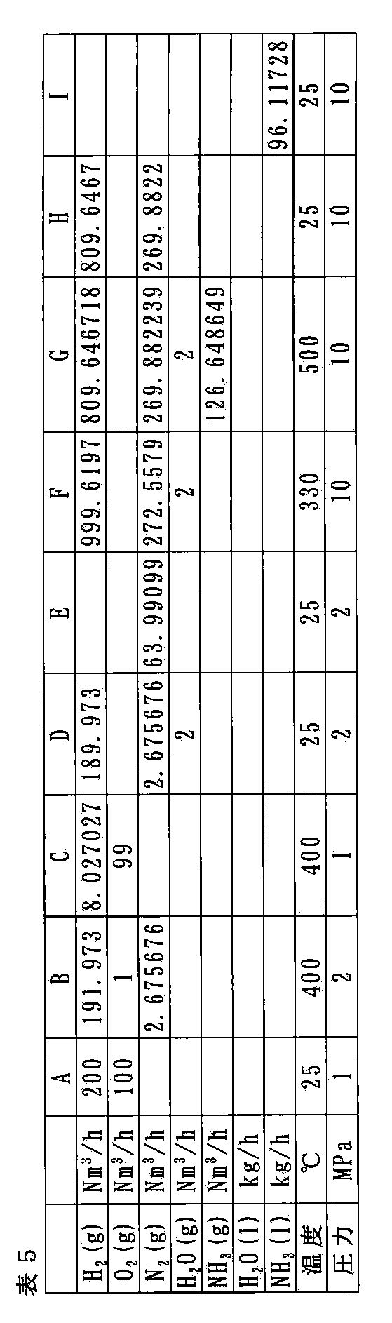
- Example 5 In the ammonia synthesis method of Example 5, oxygen in the raw material gas is removed using a hydrogen separation membrane and an oxidation catalyst. Here, a process as shown in FIG. 9 is used.
- the process shown in FIG. 9 is the same as the process of Example 3 except that ammonia is synthesized at a pressure of 10 MPa in the ammonia synthesis unit 4 and ammonia is collected using a condenser in the ammonia recovery unit 5. Is going to.
- Example 5 The material balance of the process of Example 5 is shown in Table 5 below. In this process, the amount of ammonia produced is 96.1 kg / h, and the concentration of ammonia obtained is 100%.
- Example 6 In the ammonia synthesis method of Example 6, oxygen in the raw material gas is removed using a hydrogen separation membrane and an oxidation catalyst. Here, a process as shown in FIG. 10 is used.
- Example 6 The material balance of the process of Example 6 is shown in Table 6 below. In this process, the amount of ammonia produced is 96.1 kg / h, and the concentration of ammonia obtained is 100%.
Landscapes
- Chemical & Material Sciences (AREA)
- Organic Chemistry (AREA)
- Inorganic Chemistry (AREA)
- Engineering & Computer Science (AREA)
- Combustion & Propulsion (AREA)
- Chemical Kinetics & Catalysis (AREA)
- Analytical Chemistry (AREA)
- Health & Medical Sciences (AREA)
- General Health & Medical Sciences (AREA)
- Catalysts (AREA)
- Hydrogen, Water And Hydrids (AREA)
Abstract
Description
N2+3H2→3NH3 (約400℃) (1)
(b)酸素分離膜又は水素分離膜によって、第1の原料ガスに含有される酸素を少なくとも部分的に分離及び除去して、第1の原料ガスよりも酸素濃度が低い第2の原料ガスを得る、第1の酸素除去工程、
(c)第2の原料ガス中の酸素を、水素と反応させて水として除去して、又は吸着媒体に吸着させて除去して、第2の原料ガスよりも酸素濃度が低い第3の原料ガスを得る、第2の酸素除去工程、並びに
(d)第3の原料ガス中の水素を窒素と反応させて、アンモニアを合成する、アンモニア合成工程、
を含む、アンモニア合成方法。
〈2〉水分解工程(a)において、直接熱分解法、熱化学分解法又は光触媒分解法によって水を分解して、第1の原料ガスを得る、上記〈1〉項に記載の方法。
〈3〉水分解工程(a)において、金属と金属酸化物との間の酸化還元反応を用いる熱化学分解法、又は酸化状態の異なる金属酸化物間の酸化還元反応を用いる熱化学分解法によって水を分解して、第1の原料ガスを得る、上記〈2〉項に記載の方法。
〈4〉水分解工程(a)において、酸化状態の異なる酸化鉄間の酸化還元反応を用いる熱化学分解法によって水を分解して、第1の原料ガスを得る、上記〈3〉項に記載の方法。
〈5〉水分解工程(a)及び/又はアンモニア合成工程(d)において、必要な熱エネルギーの少なくとも一部を太陽熱エネルギーから得る、上記〈1〉~〈4〉項のいずれかに記載の方法。
〈6〉水分解工程(a)及び/又はアンモニア合成工程(d)を、太陽光集光装置の集光部において実施して、必要な熱エネルギーの少なくとも一部を太陽熱エネルギーから得る、上記〈5〉項に記載の方法。
〈7〉水分解工程(a)において、金属と金属酸化物との間の酸化還元反応を用いる熱化学分解法、又は酸化状態の異なる金属酸化物間の酸化還元反応を用いる熱化学分解法によって水を分解して、第1の原料ガスを得、
水分解工程(a)を、熱分解法において用いられる金属及び/又は金属酸化物を保持している水分解部を複数有する水分解・再生装置において行い、
複数の水分解部のうちの少なくとも1つにおいて、水分解工程(a)を行っている間に、複数の水分解部のうちの他の少なくとも1つにおいて、使用済みの水分解部を再生し、且つ
再生された水分解部を、水分解工程(a)において再利用する、上記〈1〉~〈6〉項のいずれかに記載の方法。
2、2’、102 酸素分離膜(水素分離膜)保持部
3、103 酸化触媒保持部
4、104 アンモニア合成部
5、105 アンモニア回収部
100 本発明のアンモニア合成装置
150 パラボリックトラフ型の集光装置
A 水素及び酸素を含有する第1の原料ガス
B 第1の原料ガスよりも酸素濃度が低い第2の原料ガス
C 廃棄流れ
D 第2の原料ガスよりも酸素濃度が低い第3の原料ガス
E 窒素流れ
F 供給物流れ
G アンモニア含有流れ
H 再循環流れ
I アンモニア水流れ
J 液体水
本発明のアンモニア合成方法は、水分解工程(a)を含み、ここでは、水を分解して水素及び酸素を含有する第1の原料ガスを得る。
電気分解法は、水の電気分解を用いる方法であり、高純度水素を得ることができ、ランニングコスト・装置サイズの面での更なる改良が期待されている。
水の直接熱分解は、水を分解して水素と酸素とを得るための最も基本的な方法であり、下記の式1で示される反応によって、数千℃の高温下で直接に水を水素と酸素とに分解する方法である:
H2O → H2 + 1/2O2 (数千℃) (式1)
熱化学分解法は、化学反応を組み合わせることによって直接熱分解の場合よりも低い温度で水の分解を行わせる方法である。熱化学分解法、特に金属と金属酸化物との間の酸化還元反応を用いる熱化学分解法、又は酸化状態の異なる金属酸化物間の酸化還元反応を用いる熱化学分解法、より特に酸化状態の異なる酸化鉄間の酸化還元反応を用いる熱化学分解法は、スケールアップ可能であり、実用化の目処も立ちつつある。ただし、熱化学分解法で得られる水素は一般に、酸素を含有している。熱化学分解法のための熱源としては、太陽熱エネルギーや原子力熱エネルギー、特に太陽熱エネルギーを用いることができる。熱化学分解法としては非常に多くの方法が提案されており、例えば下記のような方法が考えられている。
代表的な熱化学分解法の例は、下記の反応式で、マグネシウム(Mg)、アルミニウム(Al)、鉄(Fe)等の金属とその金属酸化物との間の酸化還元反応を利用する方法である(Mは金属元素、mは金属元素Mの原子価):
M+H2O → M2/mO+H2 (式2)
M2/mO → M+1/2O2 (式3)
全反応 H2O → H2+1/2O2
3FeO+H2O → Fe3O4+H2 (式4)
Fe3O4 → 3FeO+1/2O2 (式5)
全反応 H2O→H2+1/2O2
また、他の代表的な熱化学分解法の例は、下記の反応式で示されるI−Sサイクル法として知られる方法である:
H2SO4 → H2O+SO2+1/2O2
(約950℃) (式6)
2H2O+SO2+I2 → H2SO4+2HI
(約130℃) (式7)
2HI → H2+I2 (約400℃) (式8)
全反応 H2O→H2+1/2O2
光触媒分解法は、水に接触している光触媒に光を照射することによって、水を水素と酸素とに分解する方法であり、無尽蔵の水と太陽光で水素を製造するという点で望ましい。ただし、この方法の実用化のためには更なる研究が必要とされており、また光触媒分解法で得られる水素には酸素が含まれることがある。
本発明のアンモニア合成方法は、第1の酸素除去工程(b)を含み、ここでは、酸素分離膜又は水素分離膜によって、第1の原料ガスに含有される酸素を少なくとも部分的に分離及び除去して、第1の原料ガスよりも酸素濃度が低い第2の原料ガスを得る。
本発明において用いられる「酸素分離膜」は、水素と酸素とを少なくとも含有するガスと接触させたときに、水素よりも酸素を優先的に透過させる膜として定義される。ここで、酸素の透過量と水素の透過量とのモル比(O2/H2)は例えば、操作温度において2以上、10以上、50以上、100以上、又は1,000以上である。
本発明において用いられる「水素分離膜」は、水素と酸素とを少なくとも含有するガスと接触させたときに、酸素よりも水素を優先的に透過させる膜として定義される。ここで、水素の透過量と酸素の透過量とのモル比(H2/O2)は例えば、操作温度において2以上、10以上、50以上、100以上、又は1,000以上である。
本発明のアンモニア合成方法は、第2の酸素除去工程(c)を含み、ここでは、第1の原料ガスよりも酸素濃度が低い第2の原料ガス中の酸素を、水素と反応させて水として除去して、又は吸着媒体に吸着させて除去して、第2の原料ガスよりも酸素濃度が低い第3の原料ガスを得る。
本発明において、第2の原料ガス中の酸素を水素と反応させて水として除去するためには、酸化触媒を用いることができる。なお、酸素と水素との反応によって生成した水は、ゼオライト等によって吸着すること、水を含有する原料ガスを一時的に100℃以下まで冷却して気−液分離を行うこと等によって、除去することができる。
本発明において、第2の原料ガス中の酸素を吸着させて除去するために使用される吸着媒体としては、金属酸化物の吸着媒体を挙げることができる。
本発明のアンモニア合成方法は、アンモニア合成工程(d)を含み、ここでは、第2の原料ガスよりも酸素濃度が低い第3の原料ガス中の水素を窒素と反応させて、アンモニアを合成する。
本発明のアンモニア合成方法のための他の原料である窒素は、任意の方法で得ることができ、例えば深冷分離法、膜分離法、圧力スイング吸着法等によって空気を分離して得ることが考えられる。ここで、空気の深冷分離では、空気を冷却しながら圧縮し、液体空気を作り、酸素と窒素との沸点の差を利用して、液体空気から窒素を分離する。この方法では一般に、大規模な設備が必要とされるものの、高純度の窒素が得られる。
アンモニア合成工程で生成されたアンモニアの回収は、任意の様式で行うことができ、例えばアンモニアを水に吸収させて未反応成分である水素及び窒素と分離する湿式回収工程、又はアンモニアを液化して未反応成分である水素及び窒素と分離する凝縮工程によって達成することができる。
上記記載のように、水分解工程(a)及び/又はアンモニア合成工程(d)では特に、必要な熱エネルギーの少なくとも一部を太陽熱エネルギーから得ることができる。この場合、本発明のアンモニア合成方法において、水分解工程(a)及び/又はアンモニア合成工程(d)を、太陽光集光装置の集光部において実施して、必要な熱エネルギーの少なくとも一部を太陽熱エネルギーから得ることができる。
上記記載のように、本発明のアンモニア合成方法の水分解工程(a)では、金属と金属酸化物との間の酸化還元反応を用いる熱化学分解法、又は酸化状態の異なる金属酸化物間の酸化還元反応を用いる熱化学分解法によって水を分解して、第1の原料ガスを得ることができる。
実施例1のアンモニア合成方法では、酸素分離膜及び酸化触媒を用いて、原料ガス中の酸素を除去する。ここでは、図5に示すようなプロセスを用いている。

実施例2のアンモニア合成方法では、酸素分離膜及び酸化触媒を用いて、原料ガス中の酸素を除去する。ここでは、図6に示すようなプロセスを用いている。

実施例3のアンモニア合成方法では、酸素分離膜及び酸化触媒を用いて、原料ガス中の酸素を除去する。ここでは、図7に示すようなプロセスを用いている。

実施例4のアンモニア合成方法では、水素分離膜及び酸化触媒を用いて、原料ガス中の酸素を除去する。ここでは、図8に示すようなプロセスを用いている。

実施例5のアンモニア合成方法では、水素分離膜及び酸化触媒を用いて、原料ガス中の酸素を除去する。ここでは、図9に示すようなプロセスを用いている。
実施例6のアンモニア合成方法では、水素分離膜及び酸化触媒を用いて、原料ガス中の酸素を除去する。ここでは、図10に示すようなプロセスを用いている。

Claims (7)
- (a)水を分解して、水素及び酸素を含有する第1の原料ガスを得る、水分解工程、
(b)酸素分離膜又は水素分離膜によって、前記第1の原料ガスに含有される酸素を少なくとも部分的に分離及び除去して、前記第1の原料ガスよりも酸素濃度が低い第2の原料ガスを得る、第1の酸素除去工程、
(c)前記第2の原料ガス中の酸素を、水素と反応させて水として除去して、又は吸着媒体に吸着させて除去して、前記第2の原料ガスよりも酸素濃度が低い第3の原料ガスを得る、第2の酸素除去工程、並びに
(d)前記第3の原料ガス中の水素を窒素と反応させて、アンモニアを合成する、アンモニア合成工程、
を含む、アンモニア合成方法。 - 水分解工程(a)において、直接熱分解法、熱化学分解法又は光触媒分解法によって水を分解して、前記第1の原料ガスを得る、請求項1に記載の方法。
- 水分解工程(a)において、金属と金属酸化物との間の酸化還元反応を用いる熱化学分解法、又は酸化状態の異なる金属酸化物間の酸化還元反応を用いる熱化学分解法によって水を分解して、前記第1の原料ガスを得る、請求項2に記載の方法。
- 水分解工程(a)において、酸化状態の異なる酸化鉄間の酸化還元反応を用いる熱化学分解法によって水を分解して、前記第1の原料ガスを得る、請求項3に記載の方法。
- 水分解工程(a)及び/又はアンモニア合成工程(d)において、必要な熱エネルギーの少なくとも一部を太陽熱エネルギーから得る、請求項1~4のいずれかに記載の方法。
- 水分解工程(a)及び/又はアンモニア合成工程(d)を、太陽光集光装置の集光部において実施して、必要な熱エネルギーの少なくとも一部を太陽熱エネルギーから得る、請求項5に記載の方法。
- 水分解工程(a)において、金属と金属酸化物との間の酸化還元反応を用いる熱化学分解法、又は酸化状態の異なる金属酸化物間の酸化還元反応を用いる熱化学分解法によって水を分解して、前記第1の原料ガスを得、
水分解工程(a)を、前記熱分解法において用いられる金属及び/又は金属酸化物を保持している水分解部を複数有する水分解・再生装置において行い、
複数の前記水分解部のうちの少なくとも1つにおいて、水分解工程(a)を行っている間に、複数の前記水分解部のうちの他の少なくとも1つにおいて、使用済みの水分解部を再生し、且つ
再生された前記水分解部を、水分解工程(a)において再利用する、
請求項1~6のいずれかに記載の方法。
Priority Applications (3)
| Application Number | Priority Date | Filing Date | Title |
|---|---|---|---|
| CN2009801579358A CN102348642A (zh) | 2009-01-09 | 2009-12-22 | 氨合成方法 |
| EP09837611A EP2377815A4 (en) | 2009-01-09 | 2009-12-22 | PROCESS FOR SYNTHESIS OF AMMONIA |
| US13/143,619 US8623313B2 (en) | 2009-01-09 | 2009-12-22 | Ammonia synthesis process |
Applications Claiming Priority (2)
| Application Number | Priority Date | Filing Date | Title |
|---|---|---|---|
| JP2009-003851 | 2009-01-09 | ||
| JP2009003851A JP5373410B2 (ja) | 2009-01-09 | 2009-01-09 | アンモニア合成方法 |
Publications (1)
| Publication Number | Publication Date |
|---|---|
| WO2010079726A1 true WO2010079726A1 (ja) | 2010-07-15 |
Family
ID=42316492
Family Applications (1)
| Application Number | Title | Priority Date | Filing Date |
|---|---|---|---|
| PCT/JP2009/071843 Ceased WO2010079726A1 (ja) | 2009-01-09 | 2009-12-22 | アンモニア合成方法 |
Country Status (5)
| Country | Link |
|---|---|
| US (1) | US8623313B2 (ja) |
| EP (1) | EP2377815A4 (ja) |
| JP (1) | JP5373410B2 (ja) |
| CN (1) | CN102348642A (ja) |
| WO (1) | WO2010079726A1 (ja) |
Cited By (3)
| Publication number | Priority date | Publication date | Assignee | Title |
|---|---|---|---|---|
| US9895652B2 (en) | 2013-08-14 | 2018-02-20 | Commonwealth Scientific And Industrial Research Organisation | Processes utilising selectively permeable membranes |
| US10882742B2 (en) | 2016-02-02 | 2021-01-05 | Sabic Global Technologies B.V. | Process for separation of hydrogen and oxygen |
| US11285428B2 (en) | 2016-02-02 | 2022-03-29 | Sabic Global Technologies B.V. | Process for separation of hydrogen and oxygen |
Families Citing this family (30)
| Publication number | Priority date | Publication date | Assignee | Title |
|---|---|---|---|---|
| US8272216B2 (en) | 2008-02-22 | 2012-09-25 | Toyota Jidosha Kabushiki Kaisha | Method for converting solar thermal energy |
| JP5365037B2 (ja) | 2008-03-18 | 2013-12-11 | トヨタ自動車株式会社 | 水素生成装置、アンモニア燃焼内燃機関、及び燃料電池 |
| JP5465913B2 (ja) * | 2009-04-08 | 2014-04-09 | トヨタ自動車株式会社 | アンモニア合成装置及び方法 |
| CN101880046A (zh) * | 2009-05-05 | 2010-11-10 | 中村德彦 | 复合设备 |
| US8808659B2 (en) * | 2010-01-28 | 2014-08-19 | E I Du Pont De Nemours And Company | Process and reactor system for producing ammonia using ionic liquids |
| JP5593883B2 (ja) * | 2010-07-02 | 2014-09-24 | Jfeスチール株式会社 | 炭酸ガス排出量の削減方法 |
| TWI427035B (zh) * | 2011-08-02 | 2014-02-21 | 國立屏東科技大學 | 氨製備裝置 |
| JP5821777B2 (ja) * | 2012-05-21 | 2015-11-24 | トヨタ自動車株式会社 | アンモニア合成方法 |
| WO2015019473A1 (ja) * | 2013-08-08 | 2015-02-12 | トヨタ自動車株式会社 | アンモニア合成方法 |
| JP6227355B2 (ja) * | 2013-09-27 | 2017-11-08 | スタンレー電気株式会社 | 水素製造装置 |
| WO2015192876A1 (en) * | 2014-06-16 | 2015-12-23 | Siemens Aktiengesellschaft | System and method for supplying an energy grid with energy from an intermittent renewable energy source |
| RU2663761C2 (ru) * | 2014-06-16 | 2018-08-09 | Сименс Акциенгезелльшафт | Система и способ для распределения нагрузки импульсной возобновляемой энергии для электрической сети |
| CN105692653A (zh) * | 2014-11-28 | 2016-06-22 | 中国科学院大连化学物理研究所 | 制备氨的系统及方法 |
| WO2016107868A1 (en) * | 2014-12-30 | 2016-07-07 | Gunnar Sanner | Thermal reactor |
| BR112017017399B1 (pt) * | 2015-02-17 | 2023-02-14 | Tokyo Institute Of Technology | Sistema e método de produção de um produto selecionado de um produto contendo nitrogênio e um produto fermentado e cultivado |
| JPWO2017104021A1 (ja) * | 2015-12-16 | 2018-10-04 | 日揮株式会社 | アンモニアの製造方法 |
| CN115571895A (zh) | 2016-03-01 | 2023-01-06 | 约瑟夫.比奇 | 制造电子化合物负载的金属催化剂的方法 |
| US11325105B2 (en) | 2017-05-15 | 2022-05-10 | Starfire Energy | Metal-decorated barium calcium aluminum oxide and related materials for NH3 catalysis |
| CN111163862A (zh) | 2017-05-26 | 2020-05-15 | 星火能源 | 从nh3反应器产物流移除气态nh3 |
| CN111372675B (zh) | 2017-11-25 | 2022-08-23 | 星火能源公司 | 具有集成的热交换器的化学反应器 |
| JP7374705B2 (ja) | 2018-10-23 | 2023-11-07 | つばめBhb株式会社 | アンモニア合成システムおよびアンモニアの製造方法 |
| JP7593929B2 (ja) | 2019-01-31 | 2024-12-03 | スターファイアー エナジー | Nh3合成・クラッキング用金属被覆バリウム・カルシウム・アルミニウム酸化物触媒およびその形成方法 |
| GB201904004D0 (en) | 2019-03-22 | 2019-05-08 | Oxford Univ Innovation | Photocatalyst |
| PL3947780T3 (pl) * | 2019-04-05 | 2025-12-15 | Topsoe A/S | Wstępna separacja powietrza otoczenia i soec do wytwarzania gazu syntezowego do wytwarzania amoniaku |
| JP7355720B2 (ja) | 2020-10-11 | 2023-10-03 | トヨタ自動車株式会社 | 光触媒を用いた水素ガス製造装置 |
| EP4313854A1 (en) * | 2021-03-22 | 2024-02-07 | Topsoe A/S | Combined cleaning unit for e-plants |
| CN113582200B (zh) * | 2021-06-29 | 2022-09-16 | 福州大学化肥催化剂国家工程研究中心 | 一种耦合氨分离与原料气净化的可再生能源合成氨系统 |
| CN113249147A (zh) * | 2021-06-30 | 2021-08-13 | 杨皓 | 一种焦炉煤气联产lng与合成氨的改进工艺 |
| CN114560476B (zh) * | 2022-02-23 | 2025-04-04 | 湖北和远气体股份有限公司 | 一种制备半导体用超纯氨的装置及工艺 |
| CN116081643B (zh) * | 2023-02-10 | 2025-03-07 | 四川亚联氢能科技股份有限公司 | 一种熔盐移热氨合成工艺 |
Citations (10)
| Publication number | Priority date | Publication date | Assignee | Title |
|---|---|---|---|---|
| JPS54157797A (en) * | 1978-03-20 | 1979-12-12 | Monsanto Co | Sysnthesis of ammonia |
| JP2000007325A (ja) * | 1998-06-26 | 2000-01-11 | Shigemi Sawada | アンモニアの製造方法 |
| JP2000247632A (ja) * | 1999-03-04 | 2000-09-12 | Kinya Adachi | 金属水素化物を水素源とするアンモニアの製造 |
| US6241955B1 (en) | 1998-10-02 | 2001-06-05 | Aeronex, Inc. | Method and apparatus for purification of hydride gas streams |
| JP2001240412A (ja) | 2000-02-10 | 2001-09-04 | Haldor Topsoe As | アンモニアを製造するための方法及び装置 |
| JP2002536276A (ja) * | 1999-02-03 | 2002-10-29 | テキサコ デベロプメント コーポレーション | アンモニア合成からのパージガスの利用 |
| JP2003267725A (ja) | 2002-03-15 | 2003-09-25 | Hitachi Zosen Corp | アンモニアの製造方法及びその装置並びにこれにより製造したアンモニアを用いる排煙脱硝方法 |
| JP2006528128A (ja) | 2003-07-23 | 2006-12-14 | インテグリス・インコーポレーテッド | 水と窒素からのアンモニアのユースポイント製造方法 |
| JP2008055295A (ja) | 2006-08-30 | 2008-03-13 | Ihi Corp | 水素分離膜 |
| JP2008062188A (ja) | 2006-09-07 | 2008-03-21 | Noritake Co Ltd | 酸素分離膜 |
Family Cites Families (4)
| Publication number | Priority date | Publication date | Assignee | Title |
|---|---|---|---|---|
| IL63630A (en) * | 1981-08-21 | 1985-01-31 | Ram Lavie | Process for the manufacture of ammonia |
| IL102064A (en) * | 1992-06-01 | 1995-03-30 | Yeda Res & Dev | Method and apparatus for the separate recovery of a high molecular weight gas and a low molecular weight gas from a gaseous starting mixture |
| JP2004529056A (ja) | 2001-03-06 | 2004-09-24 | アルケミックス・コーポレーション | 水素の製造方法およびその用途 |
| CN1760128A (zh) * | 2004-10-14 | 2006-04-19 | 马发军 | 一种用水和空气制造合成氨的工艺方法 |
-
2009
- 2009-01-09 JP JP2009003851A patent/JP5373410B2/ja not_active Expired - Fee Related
- 2009-12-22 US US13/143,619 patent/US8623313B2/en not_active Expired - Fee Related
- 2009-12-22 CN CN2009801579358A patent/CN102348642A/zh active Pending
- 2009-12-22 EP EP09837611A patent/EP2377815A4/en not_active Withdrawn
- 2009-12-22 WO PCT/JP2009/071843 patent/WO2010079726A1/ja not_active Ceased
Patent Citations (10)
| Publication number | Priority date | Publication date | Assignee | Title |
|---|---|---|---|---|
| JPS54157797A (en) * | 1978-03-20 | 1979-12-12 | Monsanto Co | Sysnthesis of ammonia |
| JP2000007325A (ja) * | 1998-06-26 | 2000-01-11 | Shigemi Sawada | アンモニアの製造方法 |
| US6241955B1 (en) | 1998-10-02 | 2001-06-05 | Aeronex, Inc. | Method and apparatus for purification of hydride gas streams |
| JP2002536276A (ja) * | 1999-02-03 | 2002-10-29 | テキサコ デベロプメント コーポレーション | アンモニア合成からのパージガスの利用 |
| JP2000247632A (ja) * | 1999-03-04 | 2000-09-12 | Kinya Adachi | 金属水素化物を水素源とするアンモニアの製造 |
| JP2001240412A (ja) | 2000-02-10 | 2001-09-04 | Haldor Topsoe As | アンモニアを製造するための方法及び装置 |
| JP2003267725A (ja) | 2002-03-15 | 2003-09-25 | Hitachi Zosen Corp | アンモニアの製造方法及びその装置並びにこれにより製造したアンモニアを用いる排煙脱硝方法 |
| JP2006528128A (ja) | 2003-07-23 | 2006-12-14 | インテグリス・インコーポレーテッド | 水と窒素からのアンモニアのユースポイント製造方法 |
| JP2008055295A (ja) | 2006-08-30 | 2008-03-13 | Ihi Corp | 水素分離膜 |
| JP2008062188A (ja) | 2006-09-07 | 2008-03-21 | Noritake Co Ltd | 酸素分離膜 |
Non-Patent Citations (1)
| Title |
|---|
| See also references of EP2377815A4 |
Cited By (4)
| Publication number | Priority date | Publication date | Assignee | Title |
|---|---|---|---|---|
| US9895652B2 (en) | 2013-08-14 | 2018-02-20 | Commonwealth Scientific And Industrial Research Organisation | Processes utilising selectively permeable membranes |
| US10882742B2 (en) | 2016-02-02 | 2021-01-05 | Sabic Global Technologies B.V. | Process for separation of hydrogen and oxygen |
| US11285428B2 (en) | 2016-02-02 | 2022-03-29 | Sabic Global Technologies B.V. | Process for separation of hydrogen and oxygen |
| US11850546B2 (en) | 2016-02-02 | 2023-12-26 | Sabic Global Technologies B.V. | Process for separation of hydrogen and oxygen |
Also Published As
| Publication number | Publication date |
|---|---|
| US8623313B2 (en) | 2014-01-07 |
| JP5373410B2 (ja) | 2013-12-18 |
| EP2377815A4 (en) | 2012-08-01 |
| US20110286907A1 (en) | 2011-11-24 |
| EP2377815A1 (en) | 2011-10-19 |
| CN102348642A (zh) | 2012-02-08 |
| JP2010159194A (ja) | 2010-07-22 |
Similar Documents
| Publication | Publication Date | Title |
|---|---|---|
| JP5373410B2 (ja) | アンモニア合成方法 | |
| JP7672517B2 (ja) | Nox除去を有するグリーン水素のためのアンモニア分解 | |
| CN1212965C (zh) | 烃部分氧化制氢气的方法 | |
| JP6261759B2 (ja) | 内燃機関のco2回収装置 | |
| JP2020531388A (ja) | 自己熱アンモニア分解方法 | |
| CN110180383B (zh) | 硫化氢酸性气硫氢资源协同回收装置和方法 | |
| TW200911687A (en) | Integrated processes for generating carbon monoxide for carbon nanomaterial production | |
| CA2698246C (en) | A system and process for hydrocarbon synthesis | |
| JP5549732B2 (ja) | 水素製造方法及び装置 | |
| WO2011021944A1 (en) | Combined processes for utilizing synthesis gas at low co2 emission and high energy output | |
| WO2015151992A1 (ja) | 芳香族化合物の製造システム及びその製造方法 | |
| WO2017183388A1 (ja) | 内燃機関 | |
| JP5660493B2 (ja) | アンモニアの合成方法 | |
| WO2017051610A1 (ja) | 内燃機関 | |
| CN111848352A (zh) | 一种焦炭还原co2制备甲醇的工艺方法 | |
| CN1726077A (zh) | 利用部分催化氧化产生合成气的方法 | |
| JP2000233917A (ja) | Co2からcoを製造する方法 | |
| AU2012301583A1 (en) | Integration of FT system and syn-gas generation | |
| JP2000219508A (ja) | 水素psaのオフガスからcoを製造する方法 | |
| KR102579471B1 (ko) | 이산화탄소 건식 흡수제를 이용한 일산화탄소 및 합성가스 생성 공정 및 시스템 | |
| EP4698484A1 (en) | Catalytic process using ammonia as hydrogen source for carbon dioxide conversion | |
| JP2026027748A (ja) | 燃焼式アンモニア分解装置および燃焼式アンモニア分解方法 | |
| CN101600676A (zh) | 通过催化气体反应制备二氧化碳和甲烷的方法 | |
| JP2007001792A (ja) | 水素および一酸化炭素の製造方法及び製造装置 | |
| JP2007254306A (ja) | メタノール合成装置及び方法 |
Legal Events
| Date | Code | Title | Description |
|---|---|---|---|
| WWE | Wipo information: entry into national phase |
Ref document number: 200980157935.8 Country of ref document: CN |
|
| 121 | Ep: the epo has been informed by wipo that ep was designated in this application |
Ref document number: 09837611 Country of ref document: EP Kind code of ref document: A1 |
|
| REEP | Request for entry into the european phase |
Ref document number: 2009837611 Country of ref document: EP |
|
| WWE | Wipo information: entry into national phase |
Ref document number: 5284/DELNP/2011 Country of ref document: IN Ref document number: 2009837611 Country of ref document: EP |
|
| NENP | Non-entry into the national phase |
Ref country code: DE |
|
| WWE | Wipo information: entry into national phase |
Ref document number: 13143619 Country of ref document: US |