WO2010079807A1 - 吸収性物品 - Google Patents
吸収性物品 Download PDFInfo
- Publication number
- WO2010079807A1 WO2010079807A1 PCT/JP2010/050105 JP2010050105W WO2010079807A1 WO 2010079807 A1 WO2010079807 A1 WO 2010079807A1 JP 2010050105 W JP2010050105 W JP 2010050105W WO 2010079807 A1 WO2010079807 A1 WO 2010079807A1
- Authority
- WO
- WIPO (PCT)
- Prior art keywords
- absorbent article
- width direction
- wing
- wearer
- gather
- Prior art date
- Legal status (The legal status is an assumption and is not a legal conclusion. Google has not performed a legal analysis and makes no representation as to the accuracy of the status listed.)
- Ceased
Links
Images


Classifications
-
- A—HUMAN NECESSITIES
- A61—MEDICAL OR VETERINARY SCIENCE; HYGIENE
- A61F—FILTERS IMPLANTABLE INTO BLOOD VESSELS; PROSTHESES; DEVICES PROVIDING PATENCY TO, OR PREVENTING COLLAPSING OF, TUBULAR STRUCTURES OF THE BODY, e.g. STENTS; ORTHOPAEDIC, NURSING OR CONTRACEPTIVE DEVICES; FOMENTATION; TREATMENT OR PROTECTION OF EYES OR EARS; BANDAGES, DRESSINGS OR ABSORBENT PADS; FIRST-AID KITS
- A61F13/00—Bandages or dressings; Absorbent pads
- A61F13/15—Absorbent pads, e.g. sanitary towels, swabs or tampons for external or internal application to the body; Supporting or fastening means therefor; Tampon applicators
- A61F13/45—Absorbent pads, e.g. sanitary towels, swabs or tampons for external or internal application to the body; Supporting or fastening means therefor; Tampon applicators characterised by the shape
- A61F13/47—Sanitary towels, incontinence pads or napkins
- A61F13/475—Sanitary towels, incontinence pads or napkins characterised by edge leakage prevention means
- A61F13/4751—Sanitary towels, incontinence pads or napkins characterised by edge leakage prevention means the means preventing fluid flow in a transversal direction
- A61F13/4752—Sanitary towels, incontinence pads or napkins characterised by edge leakage prevention means the means preventing fluid flow in a transversal direction the means being an upstanding barrier
- A61F13/4753—Sanitary towels, incontinence pads or napkins characterised by edge leakage prevention means the means preventing fluid flow in a transversal direction the means being an upstanding barrier the barrier being not integral with the topsheet or backsheet
-
- A—HUMAN NECESSITIES
- A61—MEDICAL OR VETERINARY SCIENCE; HYGIENE
- A61F—FILTERS IMPLANTABLE INTO BLOOD VESSELS; PROSTHESES; DEVICES PROVIDING PATENCY TO, OR PREVENTING COLLAPSING OF, TUBULAR STRUCTURES OF THE BODY, e.g. STENTS; ORTHOPAEDIC, NURSING OR CONTRACEPTIVE DEVICES; FOMENTATION; TREATMENT OR PROTECTION OF EYES OR EARS; BANDAGES, DRESSINGS OR ABSORBENT PADS; FIRST-AID KITS
- A61F13/00—Bandages or dressings; Absorbent pads
- A61F13/15—Absorbent pads, e.g. sanitary towels, swabs or tampons for external or internal application to the body; Supporting or fastening means therefor; Tampon applicators
- A61F13/45—Absorbent pads, e.g. sanitary towels, swabs or tampons for external or internal application to the body; Supporting or fastening means therefor; Tampon applicators characterised by the shape
- A61F13/47—Sanitary towels, incontinence pads or napkins
- A61F13/472—Sanitary towels, incontinence pads or napkins specially adapted for female use
-
- A—HUMAN NECESSITIES
- A61—MEDICAL OR VETERINARY SCIENCE; HYGIENE
- A61F—FILTERS IMPLANTABLE INTO BLOOD VESSELS; PROSTHESES; DEVICES PROVIDING PATENCY TO, OR PREVENTING COLLAPSING OF, TUBULAR STRUCTURES OF THE BODY, e.g. STENTS; ORTHOPAEDIC, NURSING OR CONTRACEPTIVE DEVICES; FOMENTATION; TREATMENT OR PROTECTION OF EYES OR EARS; BANDAGES, DRESSINGS OR ABSORBENT PADS; FIRST-AID KITS
- A61F13/00—Bandages or dressings; Absorbent pads
- A61F13/15—Absorbent pads, e.g. sanitary towels, swabs or tampons for external or internal application to the body; Supporting or fastening means therefor; Tampon applicators
- A61F13/45—Absorbent pads, e.g. sanitary towels, swabs or tampons for external or internal application to the body; Supporting or fastening means therefor; Tampon applicators characterised by the shape
- A61F13/47—Sanitary towels, incontinence pads or napkins
- A61F13/476—Sanitary towels, incontinence pads or napkins characterised by encircling the crotch region of the undergarment, e.g. with flaps
-
- A—HUMAN NECESSITIES
- A61—MEDICAL OR VETERINARY SCIENCE; HYGIENE
- A61F—FILTERS IMPLANTABLE INTO BLOOD VESSELS; PROSTHESES; DEVICES PROVIDING PATENCY TO, OR PREVENTING COLLAPSING OF, TUBULAR STRUCTURES OF THE BODY, e.g. STENTS; ORTHOPAEDIC, NURSING OR CONTRACEPTIVE DEVICES; FOMENTATION; TREATMENT OR PROTECTION OF EYES OR EARS; BANDAGES, DRESSINGS OR ABSORBENT PADS; FIRST-AID KITS
- A61F13/00—Bandages or dressings; Absorbent pads
- A61F13/15—Absorbent pads, e.g. sanitary towels, swabs or tampons for external or internal application to the body; Supporting or fastening means therefor; Tampon applicators
- A61F13/56—Supporting or fastening means
- A61F13/5605—Supporting or fastening means specially adapted for sanitary napkins or the like
- A61F13/5616—Supporting or fastening means specially adapted for sanitary napkins or the like using flaps, e.g. adhesive, for attachment to the undergarment
Definitions
- the present invention relates to an absorbent article including a liquid-permeable top sheet, a liquid-impermeable back sheet, and an absorber provided between the top sheet and the back sheet.
- absorbent articles such as sanitary napkins and panty liners have a vertically long shape extending from the front side (belly side) to the back side (back side) of the wearer.
- an absorbent article includes a liquid-permeable top sheet, a liquid-impermeable back sheet, and an absorbent body provided between the top sheet and the back sheet.
- Such an absorbent article is provided with a gather (a leak-proof part) that prevents the wearer's body fluid from leaking from the absorbent article.
- a gather is provided along the longitudinal direction of an absorptive article, and has a fixed end fixed to a both-sides edge of an absorber.
- the gathers are provided in a state where a string-like body such as elastic rubber is stretched. Since the stretched string-like body tries to be restored to the state before stretching, the absorbent article is rounded, and rises in a standing direction away from the surface sheet with the fixed end as a base point. For this reason, an absorptive article (especially gather) becomes easy to touch a wearer's skin, and the side leak from which body fluid leaks from the both-sides edge of an absorber can be prevented (for example, refer to patent documents 1).
- a front wing portion is provided.
- the front wing part is folded back to the crotch part (the crotch part) of the shorts and is fastened to the shorts.
- a front wing part is provided in the width direction outside of an absorptive article rather than an absorber, and extends in the width direction outside of an absorber.
- the conventional absorbent article described above has the following problems. That is, if the gather falls on the absorbent body, the body fluid may pass through the fallen gather and a side leak may occur. In order to suppress such side leakage as much as possible, it is conceivable to increase the area of the front wing part, for example, to lengthen the front wing part in the longitudinal direction of the absorbent article.
- the front wing part is too long in the longitudinal direction of the absorbent article, it becomes difficult to fold the front wing part back to the crotch part of the shorts, and the handling of the absorbent article becomes troublesome. For example, if the wearer forcibly turns the front wing part back to the crotch part of the shorts, wrinkles are generated on the top sheet or the front wing part, which may give the wearer a feeling of strangeness during use.
- an object of the present invention is to provide an absorbent article that can easily handle the absorbent article and can prevent side leakage more reliably without giving the wearer an uncomfortable feeling during use.
- the present invention has the following features.
- first feature of the present invention is that a liquid-permeable top sheet (top sheet 10), a liquid-impermeable back sheet (back sheet 20), and provided between the top sheet and the back sheet.
- An absorbent article for example, absorbent article 1 comprising an absorbent body (absorbent body 30) that is provided on the outer side in the width direction of the absorbent article with respect to the absorbent body and corresponds to the crotch part of the wearer
- a front wing portion front wing portion 60A
- a longitudinal direction of the absorbent article provided on both side edges (both side edge portions 31) of the absorbent body
- a leak-proof part for example, gather 50
- the leak-proof part is, in a plan view of the absorbent article, and summarized in that extending outward in the width direction of the absorbent article than the root portion.
- the characteristics of the present invention it is possible to provide an absorbent article that can easily handle the absorbent article without causing a feeling of incongruity at the time of use, and can reliably prevent side leakage.
- FIG. 2 is a cross-sectional view of the absorbent article 1 according to the first embodiment in a side part open state.
- FIG. 3 is a plan view of the absorbent article 1 according to the first embodiment in the side part closed state.
- FIG. 4 is a cross-sectional view of the absorbent article 1 according to the first embodiment in the side part closed state.
- FIG. 5 is a plan view of the absorbent article 1A according to the second embodiment in a side part open state.
- FIG. 6 is a cross-sectional view of the absorbent article 1A according to the second embodiment in a side part open state.
- FIG. 7 is a plan view of the absorbent article 1A according to the second embodiment in the side part closed state.
- FIG. 8 is sectional drawing in the side part closed state of 1 A of absorbent articles which concern on 2nd Embodiment (the 1).
- FIG. 9 is sectional drawing in the side part closed state of 1 A of absorbent articles which concern on 2nd Embodiment (the 2).
- FIG. 10 is a plan view of the absorbent article 1B according to the third embodiment in the side part open state.
- FIG. 11 is sectional drawing in the side part open state of the absorbent article 1B which concerns on 3rd Embodiment (the 1).
- FIG. 12 is sectional drawing in the side part open state of the absorbent article 1B which concerns on 3rd Embodiment (the 2).
- FIG. 12 is sectional drawing in the side part open state of the absorbent article 1B which concerns on 3rd Embodiment (the 2).
- FIG. 13 is sectional drawing in the side part open state of 1 C of absorbent articles which concern on the modification 1 of 3rd Embodiment.
- FIG. 14 is a plan view of the absorbent article 1D according to Modification 2 of the third embodiment in the side part open state.
- FIG. 15 is a plan view of the absorbent article 1E according to Modification 3 of the third embodiment in the side part open state.
- FIG. 16 is a plan view of the absorbent article 1F according to the fourth embodiment in a side part open state.
- FIG. 17 is a cross-sectional view of the absorbent article 1F according to the fourth embodiment in the side portion open state.
- FIG. 18 is a plan view of the absorbent article 1G according to the modification of the fourth embodiment in the side portion open state.
- FIG. 19 is a cross-sectional view of the absorbent article 1G according to the modification of the fourth embodiment in the side part open state.
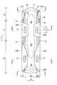
- FIG. 1 is a top view in the side part opened state of absorptive article 1 concerning a 1st embodiment.
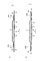
- FIG. 2A is a cross-sectional view (AA cross-sectional view of FIG. 1) in the side part open state of the absorbent article 1 according to the first embodiment.
- FIG. 2B is a cross-sectional view (cross-sectional view taken along the line BB in FIG. 1) of the absorbent article 1 according to the first embodiment in a side part open state.
- FIG. 3 is a plan view of the absorbent article 1 according to the first embodiment in the side part closed state.
- FIG. 4A is a cross-sectional view (CC cross-sectional view of FIG. 3) in the side portion closed state of the absorbent article 1 according to the first embodiment.
- FIG. 4B is a cross-sectional view (DD cross-sectional view of FIG. 3) in the side part closed state of the absorbent article 1 according to the first embodiment.
- the absorbent article 1 is a sanitary napkin.
- the absorbent article 1 has a vertically long shape extending from the front side to the rear side of the wearer.
- the absorbent article 1 includes a liquid-permeable top sheet 10 that is in contact with the wearer's skin, a liquid-impermeable back sheet 20 that is provided closer to the non-wearer than the top sheet 10, and the top sheet 10 and the back sheet 20.
- a side sheet 40 provided on the outer side in the width direction W of the absorbent body 30 orthogonal to the longitudinal direction L of the absorbent article 1.
- the absorbent article 1 is provided at both side edges 31 of the absorbent body 30, and gathers 50 (leak-proof part) extending along the longitudinal direction L of the absorbent article 1 and the absorbent article 1 more than the absorbent body 30. And a wing portion 60 that extends outside the width direction W of the absorbent body 30. The configuration of the gather 50 will be described later.
- the wing part 60 is constituted by the back sheet 20 and the side sheet 40.
- the wing part 60 is different in hue from the gather 50.
- the wing part 60 is formed of a liquid-impermeable material.
- the wing portion 60 preferably has a bending rigidity using a cantilever of 150 mm or less (particularly 100 mm or less).
- the wing part 60 is folded back to the crotch part (crotch part) of the shorts, and is provided on the back side of the wearer with respect to the front wing part 60A and the front wing part 60A, and absorbs along the shape of the shorts.
- the rear wing 60B extends outward in the width direction W of the article 1.
- the front wing 60A extends to the outside in the width direction W of the absorbent body 30 in the crotch region X1 corresponding to the crotch part of the wearer.
- the front wing portion 60A is formed with a root portion 61 that is located on the innermost side in the width direction W of the absorbent article 1 in the front wing portion 60A.
- the rear wing part 60B extends outward in the width direction W of the absorber 30 in the rear region X2 corresponding to the back side of the wearer than the front wing part 60A. That is, the rear wing part 60B is provided on the back side of the wearer than the front wing part 60A.
- an anti-slip part 70 having adhesiveness to prevent the absorbent article 1 from slipping from shorts (for example, , Hot melt).
- the gather 50 prevents the wearer's body fluid from leaking from the absorbent article 1.
- the gather 50 is formed of a nonwoven fabric or an apertured film.
- the gather 50 is formed of a sheet different from the top sheet 10 and the side sheet 40.
- the gathers 50 do not necessarily need to be comprised by another sheet
- the gather 50 rises toward the wearer side in a direction away from the top sheet 10 (hereinafter, standing direction T) when worn.
- the gathers 50 are folded back on the top sheet 10 in a side closed state of the absorbent article 1, that is, in a state where the gathers 50 are not raised.
- the side part closed state of the absorbent article 1 is a gather 50 together with the wing part 60 when the wing part 60 is folded back from the boundary between the absorbent body 30 and the wing part 60 to the surface sheet 10 side. Is arranged on the top sheet 10, and the gathers 50 are folded on the top sheet 10 a plurality of times.
- a release sheet (not shown) that covers the slip prevention part 70 is disposed between the slip prevention part 70 disposed on the uppermost side and the packaging material (not shown). It may be provided.
- a string-like body 80 (see FIGS. 2 and 4), such as rubber, which is disposed along the longitudinal direction L of the absorbent article 1 and has elasticity, is provided in a stretched state.
- the gather 50 includes a front end portion 51A located on the wearer's front side and a rear end portion 51B located on the wearer's rear side.
- the gathers 50 are joined to the absorbent article 1 in a state of being folded back and folded on the top sheet 10.
- Such a gather 50 rises toward the wearer when worn, and hollow portions are formed in the crotch region X1 and the rear region X2.
- Such a gather 50 has a gather main body 52, a fixed end 56, and a free end 57.
- the gather main body 52 has a sheet shape along the longitudinal direction L of the absorbent article 1.
- the gather main body 52 is the outermost piece portion located on the most wearer side in a state in which the gather 50 is folded a plurality of times on the topsheet 10 in a cross-sectional view in the width direction W of the absorbent article 1 (see FIG. 4).
- the outermost piece portion 53 has an outermost surface 53A located closest to the wearer in the standing direction T of the gather 50, and an outermost surface 53B located opposite to the outermost surface 53A, that is, on the lower piece portion 54 side.
- the fixed end 56 is provided along the longitudinal direction L of the absorbent article 1 and is fixed (joined) by the embossed portions E being applied to the side edge portions 31.
- the fixed end 56 should just be provided in the both-sides edge part 31 of the absorber 30, and may be provided in the width direction W outer side rather than the absorber 30, and is provided on the both-sides edge of the absorber 30. May be.
- the fixed end 56 becomes a base point when the gather 50 rises in the standing direction T. That is, the gather 50 rises in the standing direction T away from the topsheet 10 with the fixed end 56 as a base point.
- the free end 57 is provided along the longitudinal direction L of the absorbent article 1 and is located closer to the wearer than the side edges 31.
- the free end 57 is directed outward in the width direction W of the absorbent article 1 in a state where the gathers 50 are folded on the top sheet 10 a plurality of times.
- the free end 57 is located at the distal end portion of the outermost piece portion 53 and is provided outside the continuous portion 55 in the width direction W of the absorbent article 1.
- the free end 57 is provided between the gather main body 52 and the wing 60 (side seat 40) (see FIGS. 2 and 4).
- Such a gather 50 extends outside the root portion 61 in the width direction W of the absorbent article 1 in a plan view of the absorbent article 1 (see FIGS. 1 and 3). That is, the gather 50 overlaps the base portion 61. Further, at least a part of the gather 50 is joined to the wing part 60 at the joining part 58 by an adhesive such as hot melt.
- the wing portion 60 and at least a part of the outermost piece portion 53 are joined. Specifically, the side sheet 40 and the outermost surface 53 ⁇ / b> A of the outermost piece portion 53 are joined at the joining portion 58 in a state where the gathers 50 are folded a plurality of times on the topsheet 10.
- the joint portion 58 includes a front joint portion 58A provided in the front wing portion 60A and a rear joint portion 58B provided in the rear wing portion 60B.
- the front joint portion 58A includes a center line CL1 that passes through the center in the longitudinal direction L of the absorbent article 1 in the front wing portion 60A and extends along the width direction W of the absorbent article 1 in a plan view of the absorbent article 1.
- the front joint portion 58A is preferably provided evenly with respect to the center line CL1.
- a length L1 (see FIG. 1) along the longitudinal direction L of the absorbent article 1 at the front joint portion 58A is a length L2 (see FIG. 3) along the longitudinal direction L of the absorbent article 1 at the misalignment stopper 70. Longer than.
- the rear joining portion 58B has a center line CL2 that extends along the width direction W of the absorbent article 1 through the center in the longitudinal direction L of the absorbent article 1 in the rear wing portion 60B in the plan view of the absorbent article 1. It is provided in the position including.
- the joint portion 58 (the front joint portion 58A and the rear joint portion 58B) passes near the outermost width direction W of the base portion 61 and is near the reference line SL extending along the longitudinal direction L of the absorbent article 1, specifically, It is located outside the reference line SL in the width direction.
- the joint portion 58 is preferably located between the reference line SL and the center portion in the width direction W of the wing portion 60.
- the width direction W from the embossed portion E (for example, the inner end located inside the width direction W of the embossed portion E) to the joint portion 58 (for example, the outer end located inside the width direction W of the joint portion 58).
- the length Y1 is equal to or less than the length Y2 of the gather 50 from the embossed portion E to the joint portion 58 (Y1 ⁇ Y2).
- the length Y1 in the width direction W from the embossed portion E to the joint portion 58 is less than or equal to 1/2 of the length Y2 of the gather 50 from the embossed portion E to the joint portion 58, in particular, 1 / It is preferably 3 or less (see FIG. 2).
- the length Y2 of the gather 50 from the embossed portion E to the joint portion 58 is longer than the maximum length Y3 in the width direction W of the gather 50 (Y2 ⁇ Y3).
- the gather 50 extends outside the root portion 61 in the width direction W of the absorbent article 1 in a plan view of the absorbent article 1, so that the gather 50 covers the root portion 61. For this reason, side leakage can be reliably prevented without increasing the area of the front wing 60A. Thereby, it is possible to suppress the occurrence of wrinkles on the topsheet 10 and the front wing part 60 ⁇ / b> A without the root part 61 being folded back together with the wing part 60. Therefore, handling of the absorbent article 1 is facilitated without giving the wearer an uncomfortable feeling during use.
- the gather 50 may fall on the absorber 30 by the operation
- the gather 50 (leak-proof portion) is joined to the front wing portion 60A at the front joint portion 58A.
- the front joint portion 58A is located in the vicinity of the reference line SL, specifically, on the outer side in the width direction than the reference line SL. According to this, in a state where the gather 50 is opened to the outside in the width direction W of the absorbent article 1, the gather 50 is pulled to the outside in the width direction W of the absorbent article 1 together with the front wing portion 60A. For this reason, it can prevent that the gathers 50 fall down on the absorber 30, and it can suppress reliably that the both-sides edge part 31 of the absorber 30 is covered. Therefore, it is possible to prevent the absorption area of the absorber 30 from being reduced due to the fall of the gathers 50, and to prevent side leakage more reliably.
- the gather 50 has elasticity in the longitudinal direction L of the absorbent article 1. According to this, since the gather 50 stands up in the standing direction T (that is, to the wearer when the gather 50 is worn), side leakage from the root portion 61 can be further reliably prevented.
- At least a part of the gather 50 is joined to the rear wing part 60B at the rear joining part 158B. According to this, the root portion 61 located between the front wing portion 60A and the rear wing portion 60B is reliably covered by the gather 50. For this reason, side leakage (such as oblique leakage) from the base portion 61 can be further reliably prevented.
- the front joint portion 58A is provided at a position including the center line CL1 in the plan view of the absorbent article 1.
- the front joint portion 58A is preferably provided evenly with respect to the center line CL1.
- the string-like body 80 positioned before and after the front joint portion 58A expands and contracts. The power will be different.
- the front end portion 51A and the rear end portion 51B are joined to the absorbent article 1 in a state in which a plurality of gathers 50 are folded back on the top sheet 10 with the fixed end 56 as a base point.
- the gather 50 stands
- the wing part 60 is formed of a liquid-impermeable material.
- the inside of the wing part 60 or the surface on the top sheet 10 side is formed of a liquid-permeable material. According to this, even if a body fluid passes over the gather 50 and a side leak has occurred, the body fluid can be absorbed by the wing part 60. For this reason, the side leakage from the root portion 61 can be further reliably prevented.
- the wing portion 60 preferably has a bending rigidity using a cantilever of 150 mm or less. If the bending rigidity is smaller than 150 mm, the wing part 60 hardly conforms to the shape of the shorts, which may give the wearer an uncomfortable feeling during use.
- the wing part 60 is different in hue from the gather 50. According to this, a wearer becomes easy to distinguish the wing part 60 and the gather 50, and even if the wing part 60 is folded back by shorts, it can appeal to a wearer's vision that the gather 50 is not folded back. .
- the length Y1 in the width direction W from the embossed portion E to the joint portion 58 is 1 ⁇ 2 or less with respect to the length Y2 of the gather 50 from the embossed portion E to the joint portion 58, particularly 1 / 3 or less is preferable.
- the length Y1 is larger than 1 ⁇ 2 with respect to the length Y2, the gathers 50 are likely to bend, the gathers 50 are difficult to form a sufficient hollow portion, and side leakage may not be reliably prevented.
- the gather 50 in the side part closed state of the absorbent article 1, the gather 50 is arrange
- a plurality of folded in the direction T is folded on the top sheet 10. According to this, when the absorbent article 1 is individually packaged, the gathers 50 and the wing parts 60 can be folded so as to fit within the same width as the width of the absorbent body 30, and thus can be packaged in a compact manner.
- the free ends 57 are formed in the width direction of the absorbent article 1 in a state where the gathers 50 are folded back in the standing direction T and folded on the top sheet 10. W outward.
- the free end 157 has a width direction of the absorbent article 1A in a state where the gathers 150 are folded back in the standing direction T and folded on the top sheet 10. Head inside W.
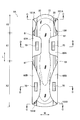
- FIG. 5 is a plan view of the absorbent article 1A according to the second embodiment in a side part open state.
- FIG. 6A is a cross-sectional view (cross-sectional view taken along line AA in FIG. 5) of the absorbent article 1A according to the second embodiment in the side portion open state.
- FIG. 6B is a cross-sectional view (cross-sectional view taken along the line BB in FIG. 5) of the absorbent article 1A according to the second embodiment in the side part open state.
- FIG. 7 is a plan view of the absorbent article 1A according to the second embodiment in the side closed state.
- FIG. 8 (a) is a cross-sectional view (CC cross-sectional view of FIG. 7) of the absorbent article 1A according to the second embodiment in a closed side portion.
- FIG. 8 (b) is a cross-sectional view (DD cross-sectional view of FIG. 7) in the side portion closed state of the absorbent article 1A according to the second embodiment.
- the gather 150 rises toward the standing direction T, that is, toward the wearer when worn. Moreover, as shown in FIG.7 and FIG.8, the gather 150 is folded back on the surface sheet 10 in the side part closed state of the absorbent article 1A, that is, the gather 150 is not raised.
- the gather 150 includes a front end portion 151A located on the front side of the wearer and a rear end portion 151B located on the back side of the wearer.
- the front end portion 151A and the rear end portion 151B are joined to the absorbent article 1A in a state where the gathers 150 are folded on the top sheet 10.
- the gather 150 has a gather main body 152, a fixed end 156, and a free end 157.
- the gather main body 152 has a sheet shape provided along the longitudinal direction L of the absorbent article 1A.
- the gather main body 152 is an outermost portion located on the most wearer side in a state in which a plurality of gathers 150 are folded and folded on the topsheet 10 in a cross-sectional view in the width direction W of the absorbent article 1A (see FIG. 8). It has at least the one piece part 153, the lower piece part 154 located in the both-sides edge part 31 side of the outermost piece part 153, and the continuous part 155 which connects the outermost piece part 153 and the lower piece part 154.
- the outermost piece portion 153 has an outermost surface 153A located closest to the wearer in the standing direction T of the gather 150, and an outermost surface 153B located opposite to the outermost surface 153A, that is, on the lower piece portion 154 side.
- the fixed end 156 is provided along the longitudinal direction L of the absorbent article 1A and is fixed to the side edges 31.
- the fixed end 156 becomes a base point when the gather 50 rises in the standing direction T. That is, the gather 150 rises in the standing direction T away from the topsheet 10 with the fixed end 156 as a base point.
- the free ends 157 are directed inward in the width direction W of the absorbent article 1A in a state in which the gathers 150 are folded back in the standing direction T and folded on the top sheet 10. Specifically, the free end 157 is located at the tip of the outermost piece portion 153 and is provided on the inner side in the width direction W of the absorbent article 1A than the continuous portion 155.
- Such a gather 150 extends from the root portion 61 to the outside in the width direction W of the absorbent article 1A in a plan view of the absorbent article 1A.
- the gather 150 overlaps the base portion 61. Further, at least a part of the gather 150 is joined to the wing portion 60 at the joint portion 158.
- the wing portion 60 and at least a part of the outermost piece portion 153 are joined. Specifically, the side sheet 40 and the outermost surface 153 ⁇ / b> A of the outermost piece portion 153 are joined at the joining portion 158 in a state where the gather 150 is folded a plurality of times on the topsheet 10.
- the joining portion 158 it is only necessary that the side sheet 40 and at least a part of the outermost surface 153A are joined. For example, as shown in FIG. 9, the side sheet 40 and a part of the lower piece part 154 are joined. Also good.
- the joint part 158 includes a front joint part 158A provided in the front wing part 60A and a rear joint part 158B provided in the rear wing part 60B.
- positioning location of 158 A of front junction parts and the back junction part 158B it is the same as that of 58 A of front junction parts and back junction part 58B which concern on 1st Embodiment mentioned above.
- the front end portion 51 ⁇ / b> A and the rear end portion 51 ⁇ / b> B of the gather 50 are in a state in which the gather 50 is folded back in the standing direction T and folded on the topsheet 10.
- the front end portion 251A and the rear end portion 251B of the gather 250 are joined to the absorbent article 1B without being folded back and folded on the top sheet 10.
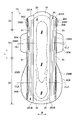
- FIG. 10 is a plan view of the absorbent article 1B according to the third embodiment in the side part open state.
- FIG. 11A is a cross-sectional view (cross-sectional view taken along line AA in FIG. 10) in the side part open state of the absorbent article 1B according to the third embodiment.
- FIG. 11B is a cross-sectional view (BB cross-sectional view of FIG. 10) in the side part open state of the absorbent article 1B according to the third embodiment.
- 3rd Embodiment demonstrates only the side part open state of the absorbent article 1B.
- the gathers 250 are provided along the longitudinal direction L of the absorbent article 1B from the front end portion 251A to the rear end portion 251B. That is, the gather 250 includes a front end portion 251A located on the front side of the wearer and a rear end portion 251B located on the back side of the wearer. The front end portion 251A and the rear end portion 251B are joined to the absorbent article 1B. The front end portion 251A and the rear end portion 251B are not folded on the top sheet 10.
- the gather 250 has a gather main body 252, a fixed end 256, and a free end 257.
- the gather main body 252 has a sheet shape provided along the longitudinal direction L of the absorbent article 1B.
- the gather main body 252 has an outer surface 252A (outermost surface) located on the wearer side and the opposite side of the outermost piece portion 153 in a cross-sectional view in the width direction W of the absorbent article 1B (see FIG. 11). And an inner side surface 252B located on the lower piece portion 154 side.
- the fixed end 256 is provided along the longitudinal direction L of the absorbent article 1B and is fixed to the side edges 31.
- the fixed end 256 serves as a base point when the gather 250 rises in the standing direction T. That is, the gather 250 rises in the standing direction T away from the topsheet 10 with the fixed end 256 as a base point.
- the free end 257 is directed outward in the width direction W of the absorbent article 1B in a state where the gather 250 is folded once in the standing direction T and folded on the top sheet 10.
- Such a gather 250 extends outward in the width direction W of the absorbent article 1B from the root portion 61 in a plan view of the absorbent article 1B. That is, the gather 250 overlaps the base portion 61. Further, at least a part of the gather 250 is joined to the wing part 60 at the joint part 258.
- the wing 60 and at least a part of the inner surface 252B are joined.
- the side sheet 40 and a part of the inner side surface 252 ⁇ / b> B are joined at the joining portion 258.
- the side sheet 40 and a part of the inner side surface 252B may be joined.
- the side sheet 40 and the inner side surface 252B of the gather 50 forming the hollow portion are joined. May be.
- the joint part 258 includes a front joint part 258A provided in the front wing part 60A and a rear joint part 258B provided in the rear wing part 60B.
- positioning location of 258A and back junction part 258B it is the same as that of 58 A of front junction parts and back junction part 58B which concern on 1st Embodiment mentioned above.
- FIG. 13 is a cross-sectional view of the absorbent article 1 ⁇ / b> C according to Modification 1 in the side part open state.
- the gather main body 252 has an outer surface 252A and an inner surface 252B.
- the gather main body 252 has an outermost piece portion 253, a lower piece portion 254, and a continuous portion 255.
- the wing part 60 and at least a part of the lower piece part 254 are joined at the joining part 258. Specifically, at the joint portion 258, the side sheet 40 and a part of the lower piece portion 254 are joined.
- the free end 257 may be directed to the outside in the width direction W of the absorbent article 1C, or may be directed to the inside in the width direction W of the absorbent article 1C.
- FIG. 14 is a plan view of the absorbent article 1D according to Modification 2 in the side part open state.
- the joint portion 258 is constituted by a front joint portion 258A and a rear joint portion 258B.
- the joint portion 258 is configured by the front joint portion 258A, the rear joint portion 258B, and the front end joint portion 258C.
- the front joint portion 258A and the rear joint portion 258B are the same as the first embodiment and the rear joint portion 58B described in the first embodiment.
- the front end joint portion 258C is provided in the front end wing portion 60C extending outward in the width direction W of the absorber 30 in the front region X3 corresponding to the front side of the wearer from the front wing portion 60A.
- the front end joint portion 258C is preferably located in the vicinity of the reference line SL, similarly to the front joint portion 58A and the rear joint portion 58B described in the first embodiment.
- FIG. 15 is a plan view of the absorbent article 1E according to Modification 3 in the side part open state.
- the gathers 250 are provided along the longitudinal direction L of the absorbent article 1B from the front end portion 251A to the rear end portion 251B.
- the gathers 250 are provided only in the vicinity of the front wing portion 60A.
- the absorbent article 1 is provided on both side edges 31 located on the outer side in the width direction W of the absorbent body 30, and extends along the longitudinal direction L of the absorbent article 1.
- the gathers 250 are provided from the root portion 61 located between the front wing portion 60A and the front end wing portion 60C to the root portion 61 located between the rear wing portion 60B and the front end wing portion 60C.
- the absorbent article 1B can be easily handled without giving the wearer an uncomfortable feeling during use. Further, it is possible to prevent side leakage from the root portion 61 more reliably.
- the absorbent article 1 in the absorbent article 1 according to the first embodiment described above, at least a part of the gather 50 has the joint portion 58.
- the gather 350 does not have a joint portion.
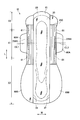
- FIG. 16 is a plan view of the absorbent article 1F according to the fourth embodiment in a side part open state.
- FIG. 17A is a cross-sectional view (cross-sectional view taken along line AA in FIG. 16) of the absorbent article 1F according to the fourth embodiment in the side part open state.
- FIG. 17B is a cross-sectional view (BB cross-sectional view of FIG. 16) in the side part open state of the absorbent article 1F according to the fourth embodiment.
- the absorbent article 1 ⁇ / b> F has a cover part 360 (a leak-proof part) in addition to the gather 350.
- the string-like body 80 is provided in an extended state.
- the gather 350 includes a front end portion 351A located on the front side of the wearer and a rear end portion 351B located on the back side of the wearer.
- the front end portion 351 ⁇ / b> A and the rear end portion 351 ⁇ / b> B are folded back on the top sheet 10.
- the cover part 360 extends to the outside in the width direction W of the absorbent article 1F.
- the cover part 360 is provided on the surface sheet 10 side with respect to the wing part 60 (the front wing part 60A and the rear wing part 60B).
- the cover part 360 is comprised by the gather 350 and the waterproof sheet 90 located in the back surface sheet 20 side.
- a water-repellent or hydrophobic nonwoven fabric or the like may be used instead of the waterproof sheet 90.
- the cover portion 360 has a long extension portion 360A that extends from the absorber 30 to the outside in the width direction and a short extension portion 360B that extends from the absorber 30 to the outside in the width direction.
- the long extension portion 360A is located on the root portion 61 in a plan view of the absorbent article 1F. 360 A of long extension parts are extended in the width direction W outer side of the absorbent article 1F rather than the root part 61 in the planar view of the absorbent article 1F. That is, the long extension portion 360 ⁇ / b> A overlaps the root portion 61.
- the short extension portion 360B is located on the wing part 60 (the front wing part 60A and the rear wing part 60B) in a plan view of the absorbent article 1F.
- the short extension portion 360 ⁇ / b> B has a shorter length extending outward in the width direction from the absorber 30 than the wing portion 60.
- the cover part 360 is not joined to the wing part 60 (the front wing part 60A, the rear wing part 60B, and the front end wing part 60C), but may be joined to the wing part 60. Moreover, the absorbent article 1F does not necessarily need to have the gather 350, and only needs to have the cover part 360.
- FIG. 18 is a plan view of the absorbent article 1G according to the modification in the side part open state.
- FIG. 19A is a cross-sectional view (AA cross-sectional view in FIG. 18) of the absorbent article 1G according to the modified example in the side part open state.
- FIG. 19 (b) is a cross-sectional view (cross-sectional view taken along the line BB in FIG. 18) of the absorbent article 1G according to the modification in the side part open state.
- the cover portion 360 is provided closer to the topsheet 10 than the wing portion 60 is.
- the cover portion 460 is provided closer to the back sheet 20 than the wing portion 60.
- the absorbent article 1 ⁇ / b> G has a cover portion 460 that overlaps the wing portion 60.
- the cover part 460 is configured by a top sheet 10A made of the same member as the top sheet 10 and a waterproof sheet 90 located on the back sheet 20 side.
- the cover portion 460 includes a long extending portion 460A that extends from the absorber 30 to the outside in the width direction, and a short extending portion 460B that extends from the absorber 30 to the outside in the width direction.
- the long extension portion 460A is located on the root portion 61 in the plan view of the absorbent article 1G.
- the long extending portion 460A extends outward in the width direction W of the absorbent article 1G from the root portion 61 in a plan view of the absorbent article 1G. That is, the long extension portion 460 ⁇ / b> A overlaps the root portion 61.
- the short extension portion 460B is located on the wing part 60 (the front wing part 60A and the rear wing part 60B) in the plan view of the absorbent article 1G.
- the short extension portion 460 ⁇ / b> B has a length that extends outward in the width direction from the absorber 30, as compared with the wing portion 60.
- the absorbent article 1F does not give the wearer an uncomfortable feeling during use.
- 1G can be easily handled, and side leakage from the root portion 61 can be prevented more reliably.
- the embodiment of the present invention can be modified as follows.
- the absorbent article 1 has been described as being a sanitary napkin, the absorbent article 1 is not limited thereto, and may be an incontinence pad, a panty liner, a disposable diaper, or the like.
- the wing part 60 was demonstrated as what is comprised by the back surface sheet 20 and the side sheet 40, it is not limited to this, For example, you may be comprised by the surface sheet 10 and the back surface sheet 20. Of course, it may be formed of a sheet other than the top sheet 10 and the back sheet 20.
- wing part 60 was demonstrated as what is comprised by the front wing part 60A and the back wing part 60B, it is not limited to this, The part extended to the width direction W outer side rather than the absorber 30 If it is.
- misalignment preventing portion 70 the surface on the back sheet 20 side in the wing portion 60 has been described as being provided with the misalignment preventing portion 70, but the present invention is not limited to this, and the misalignment preventing portion 70 may not be provided. Of course.
- the wing unit 60 has been described as having a hue different from that of the gather 50, the present invention is not limited to this, and the hue may be the same as that of the gather 50.
- the string-like body 80 is provided in the stretched state inside the gather 50, the present invention is not limited to this, and the string-like body 80 may not be provided.
- the sheets constituting the gathers 50 may be extensible.
- the shape of the gathers 50 and the way of folding may be other than those described in the above-described embodiments.
- the gather 50 has been described as having the joint portion 58, but the present invention is not limited to this, and the joint portion 58 may not be provided.
- the joining part 58 was demonstrated as what is joined to the wing part 60 with adhesives, such as hot melt, it is not limited to this, For example, it is joined to the wing part 60 by embossing, a sonic seal, etc. May be.
- joint portion 58 (the front joint portion 58A and the rear joint portion 58B) has been described as being located in the vicinity of the reference line SL.
- the present invention is not limited to this, and for example, is located on the reference line SL.
- the absorbent article 1 may be located inside or outside the width direction W with respect to the reference line SL.
- the length L1 along the longitudinal direction L of the absorbent article 1 in the front joint portion 58A has been described as being longer than the length L2 along the longitudinal direction L of the absorbent article 1 in the misalignment stopper 70.
- the present invention is not limited to this, and may be the same as the length L2, or may be shorter than the length L2.
- the front joining part 58A was demonstrated as what is provided in the position containing the center line CL1 in planar view of the absorbent article 1, it is not limited to this, The position (for example, not containing the center line CL1) Further, it may be provided on the front side or the rear side of the center line CL1.
- the back junction part 58B was demonstrated as what is provided in the position containing center line CL2 in planar view of the absorbent article 1, it is not limited to this, The position (for example, not including center line CL2) Further, it may be provided on the front side or the rear side of the center line CL2.
- the leakage preventing portion extends outward in the width direction of the absorbent article from the base portion of the wing portion, side leakage can be reliably prevented.
- the base part of the wing part is not folded back together with the wing part. There is nothing. Therefore, it is useful for absorbent articles such as sanitary napkins, incontinence pads, and panty liners.
Landscapes
- Health & Medical Sciences (AREA)
- Epidemiology (AREA)
- Heart & Thoracic Surgery (AREA)
- Engineering & Computer Science (AREA)
- Biomedical Technology (AREA)
- Vascular Medicine (AREA)
- Life Sciences & Earth Sciences (AREA)
- Animal Behavior & Ethology (AREA)
- General Health & Medical Sciences (AREA)
- Public Health (AREA)
- Veterinary Medicine (AREA)
- Fluid Mechanics (AREA)
- Physics & Mathematics (AREA)
- Absorbent Articles And Supports Therefor (AREA)
- Orthopedics, Nursing, And Contraception (AREA)
Abstract
Description
まず、第1実施形態に係る吸収性物品について、図面を参照しながら説明する。
以下において、本発明に係る第2実施形態に係る吸収性物品1Aについて、図面を参照しながら説明する。なお、上述した第1実施形態に係る吸収性物品1と同一部分には同一の符号を付して、相違する部分を主として説明する。
以下において、本発明に係る第3実施形態に係る吸収性物品1Bについて、図面を参照しながら説明する。なお、上述した第1実施形態に係る吸収性物品1と同一部分には同一の符号を付して、相違する部分を主として説明する。
次に、第3実施形態に係る吸収性物品1Bの変形例について、図面を参照しながら説明する。なお、上述した第3実施形態に係る吸収性物品1Bと同一部分には同一の符号を付して、相違する部分を主として説明する。
以下において、本発明に係る第4実施形態に係る吸収性物品1Fについて、図面を参照しながら説明する。なお、上述した第1実施形態に係る吸収性物品1と同一部分には同一の符号を付して、相違する部分を主として説明する。
上述したように、本発明の実施形態を通じて本発明の内容を開示したが、この開示の一部をなす論述及び図面は、本発明を限定するものであると理解すべきではない。この開示から当業者には様々な代替実施の形態、実施例及び運用技術が明らかとなろう。
Claims (10)
- 液透過性の表面シートと、液不透過性の裏面シートと、前記表面シートと前記裏面シートとの間に設けられる吸収体とを備える吸収性物品であって、
前記吸収体よりも前記吸収性物品の幅方向外側に設けられ、着用者の股下部に対応する股下領域において前記吸収体の幅方向外側に延出する前方ウィング部と、
前記吸収体の両側縁部に設けられ、前記吸収性物品の長手方向に沿って延び、着用者の体液が前記吸収性物品から漏れることを防止する防漏部と
を備え、
前記前方ウィング部は、前記前方ウィング部のうち最も前記吸収性物品の幅方向内側に位置する付け根部分を有し、
前記防漏部は、前記吸収性物品の平面視において、前記付け根部分よりも前記吸収性物品の幅方向外側に延出する吸収性物品。 - 前記防漏部の少なくとも一部は、前記前方ウィング部と接合される前方接合部分を有し、 前記前方接合部分は、前記付け根部分の最も幅方向内側を通り、前記吸収性物品の長手方向に沿って延びる基準線上、または前記基準線よりも幅方向外側に位置する請求項1に記載の吸収性物品。
- 前記吸収体よりも前記吸収性物品の幅方向外側に設けられ、前記前方ウィング部よりも着用者の後ろ側に対応する後方領域において前記吸収体の幅方向外側に延出する後方ウィング部をさらに備え、
前記防漏部の少なくとも一部は、前記後方ウィング部と接合される後方接合部分を有する請求項1または2に記載の吸収性物品。 - 前記防漏部は、前記吸収性物品の長手方向に伸縮性を有する請求項1乃至3の何れか一項に記載の吸収性物品。
- 前記前方接合部分は、前記前方ウィング部における前記吸収性物品の長手方向中心を通り、前記吸収性物品の幅方向に沿って延びる中心線を含む位置に設けられる請求項2乃至4の何れか一項に記載の吸収性物品。
- 前記防漏部は、
前記両側縁部に固定される固定端と、
前記着用者の前側に位置する前端部分と、
前記着用者の後ろ側に位置する後端部分と
を備え、
前記前端部分及び前記後端部分は、前記固定端を基点として前記表面シートから離れる起立方向へ折り返されて前記表面シート上に畳まれた状態において、前記吸収性物品に接合される請求項1乃至5の何れか一項に記載の吸収性物品。 - 前記防漏部は、前記吸収性物品の長手方向に沿って設けられ、前記固定端の他端となる自由端を備え、
前記自由端は、前記防漏部が前記起立方向へ折り返されて前記表面シート上に畳まれた状態において、前記吸収性物品の幅方向外側に向かう請求項6に記載の吸収性物品。 - 前記防漏部は、前記吸収性物品の長手方向に沿って設けられ、前記固定端の他端となる自由端を有し、
前記自由端は、前記防漏部が前記起立方向へ折り返されて前記表面シート上に畳まれた状態において、前記吸収性物品の幅方向内側に向かう請求項6に記載の吸収性物品。 - 前記防漏部は、前記防漏部が前記起立方向へ折り返されて前記表面シート上に畳まれた状態において、最も前記着用者側に位置する最外面を有し、
前記最外面の少なくとも一部は、前記前方ウィング部と前記前方接合部分にて接合される請求項7又は8に記載の吸収性物品。 - 前記吸収体よりも前記吸収性物品の幅方向外側に設けられ、前記前方ウィング部よりも着用者の後ろ側に対応する後方領域において前記吸収体の幅方向外側に延出する後方ウィング部をさらに備え、
前記最外面の少なくとも一部は、前記後方ウィング部と接合される後方接合部分を有する請求項9に記載の吸収性物品。
Priority Applications (5)
| Application Number | Priority Date | Filing Date | Title |
|---|---|---|---|
| CN201080004136XA CN102271636A (zh) | 2009-01-07 | 2010-01-07 | 吸收性物品 |
| AU2010203983A AU2010203983A1 (en) | 2009-01-07 | 2010-01-07 | Absorbent article |
| EP10729227.8A EP2386278A4 (en) | 2009-01-07 | 2010-01-07 | VOIDABLE ARTICLE |
| US13/143,678 US20120046630A1 (en) | 2009-01-07 | 2010-01-07 | Absorbent article |
| KR1020117018311A KR101488794B1 (ko) | 2009-01-07 | 2010-01-07 | 흡수성 물품 |
Applications Claiming Priority (2)
| Application Number | Priority Date | Filing Date | Title |
|---|---|---|---|
| JP2009002086A JP5261200B2 (ja) | 2009-01-07 | 2009-01-07 | 吸収性物品 |
| JP2009-002086 | 2009-01-07 |
Publications (1)
| Publication Number | Publication Date |
|---|---|
| WO2010079807A1 true WO2010079807A1 (ja) | 2010-07-15 |
Family
ID=42316572
Family Applications (1)
| Application Number | Title | Priority Date | Filing Date |
|---|---|---|---|
| PCT/JP2010/050105 Ceased WO2010079807A1 (ja) | 2009-01-07 | 2010-01-07 | 吸収性物品 |
Country Status (7)
| Country | Link |
|---|---|
| US (1) | US20120046630A1 (ja) |
| EP (1) | EP2386278A4 (ja) |
| JP (1) | JP5261200B2 (ja) |
| KR (1) | KR101488794B1 (ja) |
| CN (1) | CN102271636A (ja) |
| AU (1) | AU2010203983A1 (ja) |
| WO (1) | WO2010079807A1 (ja) |
Cited By (1)
| Publication number | Priority date | Publication date | Assignee | Title |
|---|---|---|---|---|
| CN102614051A (zh) * | 2011-09-30 | 2012-08-01 | 尤妮佳股份有限公司 | 吸收性物品 |
Families Citing this family (4)
| Publication number | Priority date | Publication date | Assignee | Title |
|---|---|---|---|---|
| DE102011010269A1 (de) * | 2011-01-25 | 2012-07-26 | Paul Hartmann Ag | Damen- oder Inkontinezbinde |
| JP6537658B1 (ja) * | 2018-03-28 | 2019-07-03 | 大王製紙株式会社 | 吸収性物品 |
| JP6726705B2 (ja) * | 2018-06-29 | 2020-07-22 | ユニ・チャーム株式会社 | 吸収性物品 |
| JP7025496B1 (ja) | 2020-08-27 | 2022-02-24 | 花王株式会社 | 吸収性物品 |
Citations (5)
| Publication number | Priority date | Publication date | Assignee | Title |
|---|---|---|---|---|
| JPH08336556A (ja) * | 1995-04-03 | 1996-12-24 | Mcneil Ppc Inc | 漏れの保護の向上のための多重折り畳み側面障壁 |
| JP2000288025A (ja) | 1999-04-07 | 2000-10-17 | Kao Corp | 吸収性物品 |
| JP2003290277A (ja) * | 2002-03-29 | 2003-10-14 | Daio Paper Corp | 吸収性物品 |
| JP2007111555A (ja) * | 2001-12-20 | 2007-05-10 | Kao Corp | 吸収性物品 |
| JP2009002086A (ja) | 2007-06-22 | 2009-01-08 | Panasonic Electric Works Co Ltd | 外装パネル用役物 |
Family Cites Families (16)
| Publication number | Priority date | Publication date | Assignee | Title |
|---|---|---|---|---|
| JP3217822B2 (ja) * | 1991-11-21 | 2001-10-15 | 株式会社資生堂 | 生理用ナプキンおよびその製造方法 |
| JPH05220191A (ja) * | 1992-02-12 | 1993-08-31 | Shiseido Co Ltd | 生理用ナプキンおよびその製造方法 |
| JP2559755Y2 (ja) * | 1992-11-17 | 1998-01-19 | ユニ・チャーム株式会社 | 生理用ナプキン |
| PH31459A (en) * | 1992-11-30 | 1998-11-03 | Procter & Gamble | Absorbent article having elasticized side flaps and wings. |
| GB2296445B (en) * | 1994-12-27 | 1998-12-30 | Kao Corp | Sanitary napkin |
| JP2000254173A (ja) * | 1999-03-11 | 2000-09-19 | Uni Charm Corp | 生理用ナプキン |
| JP3922897B2 (ja) * | 2001-07-12 | 2007-05-30 | ユニ・チャーム株式会社 | 生理用ナプキン |
| JP2003024373A (ja) * | 2001-07-13 | 2003-01-28 | Uni Charm Corp | ナプキン包装体 |
| JP3919638B2 (ja) * | 2001-12-20 | 2007-05-30 | 花王株式会社 | 吸収性物品 |
| JP3994377B2 (ja) * | 2002-01-21 | 2007-10-17 | 大王製紙株式会社 | 吸収性物品 |
| JP4421222B2 (ja) * | 2003-06-09 | 2010-02-24 | ユニ・チャーム株式会社 | 吸収性物品 |
| JP4644588B2 (ja) * | 2005-11-25 | 2011-03-02 | 大王製紙株式会社 | 吸収性物品 |
| JP4836639B2 (ja) * | 2006-04-12 | 2011-12-14 | 花王株式会社 | 吸収性物品 |
| JP4954696B2 (ja) * | 2006-12-27 | 2012-06-20 | 大王製紙株式会社 | 吸収性物品 |
| JP4976123B2 (ja) * | 2006-12-27 | 2012-07-18 | 大王製紙株式会社 | 吸収性物品 |
| JP5129521B2 (ja) * | 2007-06-29 | 2013-01-30 | ユニ・チャーム株式会社 | 吸収性物品 |
-
2009
- 2009-01-07 JP JP2009002086A patent/JP5261200B2/ja not_active Expired - Fee Related
-
2010
- 2010-01-07 AU AU2010203983A patent/AU2010203983A1/en not_active Abandoned
- 2010-01-07 CN CN201080004136XA patent/CN102271636A/zh active Pending
- 2010-01-07 KR KR1020117018311A patent/KR101488794B1/ko not_active Expired - Fee Related
- 2010-01-07 EP EP10729227.8A patent/EP2386278A4/en not_active Withdrawn
- 2010-01-07 WO PCT/JP2010/050105 patent/WO2010079807A1/ja not_active Ceased
- 2010-01-07 US US13/143,678 patent/US20120046630A1/en not_active Abandoned
Patent Citations (5)
| Publication number | Priority date | Publication date | Assignee | Title |
|---|---|---|---|---|
| JPH08336556A (ja) * | 1995-04-03 | 1996-12-24 | Mcneil Ppc Inc | 漏れの保護の向上のための多重折り畳み側面障壁 |
| JP2000288025A (ja) | 1999-04-07 | 2000-10-17 | Kao Corp | 吸収性物品 |
| JP2007111555A (ja) * | 2001-12-20 | 2007-05-10 | Kao Corp | 吸収性物品 |
| JP2003290277A (ja) * | 2002-03-29 | 2003-10-14 | Daio Paper Corp | 吸収性物品 |
| JP2009002086A (ja) | 2007-06-22 | 2009-01-08 | Panasonic Electric Works Co Ltd | 外装パネル用役物 |
Non-Patent Citations (1)
| Title |
|---|
| See also references of EP2386278A4 |
Cited By (1)
| Publication number | Priority date | Publication date | Assignee | Title |
|---|---|---|---|---|
| CN102614051A (zh) * | 2011-09-30 | 2012-08-01 | 尤妮佳股份有限公司 | 吸收性物品 |
Also Published As
| Publication number | Publication date |
|---|---|
| KR20110107365A (ko) | 2011-09-30 |
| JP2010158368A (ja) | 2010-07-22 |
| KR101488794B1 (ko) | 2015-02-04 |
| AU2010203983A1 (en) | 2011-08-25 |
| CN102271636A (zh) | 2011-12-07 |
| EP2386278A1 (en) | 2011-11-16 |
| US20120046630A1 (en) | 2012-02-23 |
| EP2386278A4 (en) | 2014-01-15 |
| JP5261200B2 (ja) | 2013-08-14 |
Similar Documents
| Publication | Publication Date | Title |
|---|---|---|
| JP5319263B2 (ja) | 吸収性物品 | |
| JP5404379B2 (ja) | 吸収性物品 | |
| WO2017213094A1 (ja) | 吸収性物品 | |
| JP2009207598A (ja) | 吸収性物品 | |
| JP5261200B2 (ja) | 吸収性物品 | |
| TW201737879A (zh) | 吸收性物品 | |
| JP5685421B2 (ja) | 吸収性物品 | |
| JP5756004B2 (ja) | 吸収性物品 | |
| JP5773591B2 (ja) | 吸収性物品 | |
| JP6284175B2 (ja) | 吸収性物品 | |
| JP2009172294A (ja) | 吸収性物品 | |
| JP5978349B1 (ja) | 吸収性物品 | |
| JP5476166B2 (ja) | 吸収性物品 | |
| JP5139199B2 (ja) | 吸収性物品 | |
| JP2009195309A (ja) | 使い捨て吸収性物品および包装体 | |
| JP5149105B2 (ja) | 吸収性物品 | |
| JP6051285B1 (ja) | 吸収性物品 | |
| JP5139198B2 (ja) | 吸収性物品 | |
| JP2016221136A (ja) | 吸収性物品 | |
| JP2007135943A (ja) | 吸収性物品 | |
| CN110087603B (zh) | 吸收性物品 | |
| JP2019118578A (ja) | 吸収性物品 | |
| JP2008104544A (ja) | 吸収性物品の包装構造 | |
| CN114502125A (zh) | 吸收性物品 | |
| JP2019118577A (ja) | 吸収性物品 |
Legal Events
| Date | Code | Title | Description |
|---|---|---|---|
| WWE | Wipo information: entry into national phase |
Ref document number: 201080004136.X Country of ref document: CN |
|
| 121 | Ep: the epo has been informed by wipo that ep was designated in this application |
Ref document number: 10729227 Country of ref document: EP Kind code of ref document: A1 |
|
| NENP | Non-entry into the national phase |
Ref country code: DE |
|
| ENP | Entry into the national phase |
Ref document number: 20117018311 Country of ref document: KR Kind code of ref document: A |
|
| WWE | Wipo information: entry into national phase |
Ref document number: 2010729227 Country of ref document: EP |
|
| ENP | Entry into the national phase |
Ref document number: 2010203983 Country of ref document: AU Date of ref document: 20100107 Kind code of ref document: A |
|
| WWE | Wipo information: entry into national phase |
Ref document number: 13143678 Country of ref document: US |