WO2010082508A1 - 符号化方法、復号方法、符号化装置、復号装置、プログラム、及び集積回路 - Google Patents
符号化方法、復号方法、符号化装置、復号装置、プログラム、及び集積回路 Download PDFInfo
- Publication number
- WO2010082508A1 WO2010082508A1 PCT/JP2010/000261 JP2010000261W WO2010082508A1 WO 2010082508 A1 WO2010082508 A1 WO 2010082508A1 JP 2010000261 W JP2010000261 W JP 2010000261W WO 2010082508 A1 WO2010082508 A1 WO 2010082508A1
- Authority
- WO
- WIPO (PCT)
- Prior art keywords
- image
- unit
- field
- encoding
- access unit
- Prior art date
- Legal status (The legal status is an assumption and is not a legal conclusion. Google has not performed a legal analysis and makes no representation as to the accuracy of the status listed.)
- Ceased
Links
Images


Classifications
-
- H—ELECTRICITY
- H04—ELECTRIC COMMUNICATION TECHNIQUE
- H04N—PICTORIAL COMMUNICATION, e.g. TELEVISION
- H04N19/00—Methods or arrangements for coding, decoding, compressing or decompressing digital video signals
- H04N19/50—Methods or arrangements for coding, decoding, compressing or decompressing digital video signals using predictive coding
- H04N19/597—Methods or arrangements for coding, decoding, compressing or decompressing digital video signals using predictive coding specially adapted for multi-view video sequence encoding
-
- G—PHYSICS
- G11—INFORMATION STORAGE
- G11B—INFORMATION STORAGE BASED ON RELATIVE MOVEMENT BETWEEN RECORD CARRIER AND TRANSDUCER
- G11B27/00—Editing; Indexing; Addressing; Timing or synchronising; Monitoring; Measuring tape travel
- G11B27/10—Indexing; Addressing; Timing or synchronising; Measuring tape travel
- G11B27/19—Indexing; Addressing; Timing or synchronising; Measuring tape travel by using information detectable on the record carrier
- G11B27/28—Indexing; Addressing; Timing or synchronising; Measuring tape travel by using information detectable on the record carrier by using information signals recorded by the same method as the main recording
- G11B27/30—Indexing; Addressing; Timing or synchronising; Measuring tape travel by using information detectable on the record carrier by using information signals recorded by the same method as the main recording on the same track as the main recording
- G11B27/3027—Indexing; Addressing; Timing or synchronising; Measuring tape travel by using information detectable on the record carrier by using information signals recorded by the same method as the main recording on the same track as the main recording used signal is digitally coded
-
- G—PHYSICS
- G11—INFORMATION STORAGE
- G11B—INFORMATION STORAGE BASED ON RELATIVE MOVEMENT BETWEEN RECORD CARRIER AND TRANSDUCER
- G11B27/00—Editing; Indexing; Addressing; Timing or synchronising; Monitoring; Measuring tape travel
- G11B27/10—Indexing; Addressing; Timing or synchronising; Measuring tape travel
- G11B27/19—Indexing; Addressing; Timing or synchronising; Measuring tape travel by using information detectable on the record carrier
- G11B27/28—Indexing; Addressing; Timing or synchronising; Measuring tape travel by using information detectable on the record carrier by using information signals recorded by the same method as the main recording
- G11B27/32—Indexing; Addressing; Timing or synchronising; Measuring tape travel by using information detectable on the record carrier by using information signals recorded by the same method as the main recording on separate auxiliary tracks of the same or an auxiliary record carrier
- G11B27/327—Table of contents
- G11B27/329—Table of contents on a disc [VTOC]
-
- H—ELECTRICITY
- H04—ELECTRIC COMMUNICATION TECHNIQUE
- H04N—PICTORIAL COMMUNICATION, e.g. TELEVISION
- H04N13/00—Stereoscopic video systems; Multi-view video systems; Details thereof
-
- H—ELECTRICITY
- H04—ELECTRIC COMMUNICATION TECHNIQUE
- H04N—PICTORIAL COMMUNICATION, e.g. TELEVISION
- H04N13/00—Stereoscopic video systems; Multi-view video systems; Details thereof
- H04N13/10—Processing, recording or transmission of stereoscopic or multi-view image signals
- H04N13/106—Processing image signals
- H04N13/161—Encoding, multiplexing or demultiplexing different image signal components
-
- H—ELECTRICITY
- H04—ELECTRIC COMMUNICATION TECHNIQUE
- H04N—PICTORIAL COMMUNICATION, e.g. TELEVISION
- H04N13/00—Stereoscopic video systems; Multi-view video systems; Details thereof
- H04N13/10—Processing, recording or transmission of stereoscopic or multi-view image signals
- H04N13/106—Processing image signals
- H04N13/172—Processing image signals image signals comprising non-image signal components, e.g. headers or format information
- H04N13/178—Metadata, e.g. disparity information
-
- H—ELECTRICITY
- H04—ELECTRIC COMMUNICATION TECHNIQUE
- H04N—PICTORIAL COMMUNICATION, e.g. TELEVISION
- H04N13/00—Stereoscopic video systems; Multi-view video systems; Details thereof
- H04N13/10—Processing, recording or transmission of stereoscopic or multi-view image signals
- H04N13/106—Processing image signals
- H04N13/172—Processing image signals image signals comprising non-image signal components, e.g. headers or format information
- H04N13/183—On-screen display [OSD] information, e.g. subtitles or menus
-
- H—ELECTRICITY
- H04—ELECTRIC COMMUNICATION TECHNIQUE
- H04N—PICTORIAL COMMUNICATION, e.g. TELEVISION
- H04N13/00—Stereoscopic video systems; Multi-view video systems; Details thereof
- H04N13/10—Processing, recording or transmission of stereoscopic or multi-view image signals
- H04N13/189—Recording image signals; Reproducing recorded image signals
-
- H—ELECTRICITY
- H04—ELECTRIC COMMUNICATION TECHNIQUE
- H04N—PICTORIAL COMMUNICATION, e.g. TELEVISION
- H04N19/00—Methods or arrangements for coding, decoding, compressing or decompressing digital video signals
- H04N19/10—Methods or arrangements for coding, decoding, compressing or decompressing digital video signals using adaptive coding
- H04N19/102—Methods or arrangements for coding, decoding, compressing or decompressing digital video signals using adaptive coding characterised by the element, parameter or selection affected or controlled by the adaptive coding
- H04N19/103—Selection of coding mode or of prediction mode
- H04N19/112—Selection of coding mode or of prediction mode according to a given display mode, e.g. for interlaced or progressive display mode
-
- H—ELECTRICITY
- H04—ELECTRIC COMMUNICATION TECHNIQUE
- H04N—PICTORIAL COMMUNICATION, e.g. TELEVISION
- H04N19/00—Methods or arrangements for coding, decoding, compressing or decompressing digital video signals
- H04N19/10—Methods or arrangements for coding, decoding, compressing or decompressing digital video signals using adaptive coding
- H04N19/102—Methods or arrangements for coding, decoding, compressing or decompressing digital video signals using adaptive coding characterised by the element, parameter or selection affected or controlled by the adaptive coding
- H04N19/124—Quantisation
-
- H—ELECTRICITY
- H04—ELECTRIC COMMUNICATION TECHNIQUE
- H04N—PICTORIAL COMMUNICATION, e.g. TELEVISION
- H04N19/00—Methods or arrangements for coding, decoding, compressing or decompressing digital video signals
- H04N19/10—Methods or arrangements for coding, decoding, compressing or decompressing digital video signals using adaptive coding
- H04N19/134—Methods or arrangements for coding, decoding, compressing or decompressing digital video signals using adaptive coding characterised by the element, parameter or criterion affecting or controlling the adaptive coding
- H04N19/146—Data rate or code amount at the encoder output
- H04N19/15—Data rate or code amount at the encoder output by monitoring actual compressed data size at the memory before deciding storage at the transmission buffer
-
- H—ELECTRICITY
- H04—ELECTRIC COMMUNICATION TECHNIQUE
- H04N—PICTORIAL COMMUNICATION, e.g. TELEVISION
- H04N19/00—Methods or arrangements for coding, decoding, compressing or decompressing digital video signals
- H04N19/10—Methods or arrangements for coding, decoding, compressing or decompressing digital video signals using adaptive coding
- H04N19/134—Methods or arrangements for coding, decoding, compressing or decompressing digital video signals using adaptive coding characterised by the element, parameter or criterion affecting or controlling the adaptive coding
- H04N19/146—Data rate or code amount at the encoder output
- H04N19/152—Data rate or code amount at the encoder output by measuring the fullness of the transmission buffer
-
- H—ELECTRICITY
- H04—ELECTRIC COMMUNICATION TECHNIQUE
- H04N—PICTORIAL COMMUNICATION, e.g. TELEVISION
- H04N19/00—Methods or arrangements for coding, decoding, compressing or decompressing digital video signals
- H04N19/10—Methods or arrangements for coding, decoding, compressing or decompressing digital video signals using adaptive coding
- H04N19/169—Methods or arrangements for coding, decoding, compressing or decompressing digital video signals using adaptive coding characterised by the coding unit, i.e. the structural portion or semantic portion of the video signal being the object or the subject of the adaptive coding
- H04N19/17—Methods or arrangements for coding, decoding, compressing or decompressing digital video signals using adaptive coding characterised by the coding unit, i.e. the structural portion or semantic portion of the video signal being the object or the subject of the adaptive coding the unit being an image region, e.g. an object
- H04N19/172—Methods or arrangements for coding, decoding, compressing or decompressing digital video signals using adaptive coding characterised by the coding unit, i.e. the structural portion or semantic portion of the video signal being the object or the subject of the adaptive coding the unit being an image region, e.g. an object the region being a picture, frame or field
-
- H—ELECTRICITY
- H04—ELECTRIC COMMUNICATION TECHNIQUE
- H04N—PICTORIAL COMMUNICATION, e.g. TELEVISION
- H04N19/00—Methods or arrangements for coding, decoding, compressing or decompressing digital video signals
- H04N19/70—Methods or arrangements for coding, decoding, compressing or decompressing digital video signals characterised by syntax aspects related to video coding, e.g. related to compression standards
-
- H—ELECTRICITY
- H04—ELECTRIC COMMUNICATION TECHNIQUE
- H04N—PICTORIAL COMMUNICATION, e.g. TELEVISION
- H04N5/00—Details of television systems
- H04N5/76—Television signal recording
- H04N5/765—Interface circuits between an apparatus for recording and another apparatus
-
- H—ELECTRICITY
- H04—ELECTRIC COMMUNICATION TECHNIQUE
- H04N—PICTORIAL COMMUNICATION, e.g. TELEVISION
- H04N5/00—Details of television systems
- H04N5/76—Television signal recording
- H04N5/84—Television signal recording using optical recording
- H04N5/85—Television signal recording using optical recording on discs or drums
-
- H—ELECTRICITY
- H04—ELECTRIC COMMUNICATION TECHNIQUE
- H04N—PICTORIAL COMMUNICATION, e.g. TELEVISION
- H04N9/00—Details of colour television systems
- H04N9/79—Processing of colour television signals in connection with recording
- H04N9/80—Transformation of the television signal for recording, e.g. modulation, frequency changing; Inverse transformation for playback
- H04N9/804—Transformation of the television signal for recording, e.g. modulation, frequency changing; Inverse transformation for playback involving pulse code modulation of the colour picture signal components
- H04N9/8042—Transformation of the television signal for recording, e.g. modulation, frequency changing; Inverse transformation for playback involving pulse code modulation of the colour picture signal components involving data reduction
-
- H—ELECTRICITY
- H04—ELECTRIC COMMUNICATION TECHNIQUE
- H04N—PICTORIAL COMMUNICATION, e.g. TELEVISION
- H04N9/00—Details of colour television systems
- H04N9/79—Processing of colour television signals in connection with recording
- H04N9/80—Transformation of the television signal for recording, e.g. modulation, frequency changing; Inverse transformation for playback
- H04N9/82—Transformation of the television signal for recording, e.g. modulation, frequency changing; Inverse transformation for playback the individual colour picture signal components being recorded simultaneously only
- H04N9/8205—Transformation of the television signal for recording, e.g. modulation, frequency changing; Inverse transformation for playback the individual colour picture signal components being recorded simultaneously only involving the multiplexing of an additional signal and the colour video signal
- H04N9/8211—Transformation of the television signal for recording, e.g. modulation, frequency changing; Inverse transformation for playback the individual colour picture signal components being recorded simultaneously only involving the multiplexing of an additional signal and the colour video signal the additional signal being a sound signal
-
- H—ELECTRICITY
- H04—ELECTRIC COMMUNICATION TECHNIQUE
- H04N—PICTORIAL COMMUNICATION, e.g. TELEVISION
- H04N9/00—Details of colour television systems
- H04N9/79—Processing of colour television signals in connection with recording
- H04N9/80—Transformation of the television signal for recording, e.g. modulation, frequency changing; Inverse transformation for playback
- H04N9/82—Transformation of the television signal for recording, e.g. modulation, frequency changing; Inverse transformation for playback the individual colour picture signal components being recorded simultaneously only
- H04N9/8205—Transformation of the television signal for recording, e.g. modulation, frequency changing; Inverse transformation for playback the individual colour picture signal components being recorded simultaneously only involving the multiplexing of an additional signal and the colour video signal
- H04N9/8233—Transformation of the television signal for recording, e.g. modulation, frequency changing; Inverse transformation for playback the individual colour picture signal components being recorded simultaneously only involving the multiplexing of an additional signal and the colour video signal the additional signal being a character code signal
-
- G—PHYSICS
- G11—INFORMATION STORAGE
- G11B—INFORMATION STORAGE BASED ON RELATIVE MOVEMENT BETWEEN RECORD CARRIER AND TRANSDUCER
- G11B2220/00—Record carriers by type
- G11B2220/20—Disc-shaped record carriers
- G11B2220/21—Disc-shaped record carriers characterised in that the disc is of read-only, rewritable, or recordable type
- G11B2220/213—Read-only discs
-
- G—PHYSICS
- G11—INFORMATION STORAGE
- G11B—INFORMATION STORAGE BASED ON RELATIVE MOVEMENT BETWEEN RECORD CARRIER AND TRANSDUCER
- G11B2220/00—Record carriers by type
- G11B2220/20—Disc-shaped record carriers
- G11B2220/25—Disc-shaped record carriers characterised in that the disc is based on a specific recording technology
- G11B2220/2537—Optical discs
- G11B2220/2541—Blu-ray discs; Blue laser DVR discs
Definitions
- the present invention can be used for any multimedia data encoding method and decoding method, in particular H.264. It can be used for the encoding method and the decoding method of H.264 / MPEG-4 AVC multi-view video.
- One of the methods is to show two images separately to the left and right eyes of the viewer. This is called stereo imaging in which two images are taken using two cameras.
- One of the techniques previously used to display stereoscopic images is to filter the color components so that they can be viewed with one eye at a time. Such techniques reduce the resolution of the image that reaches each eye.
- H.264 / MPEG-4 AVC multi-view video coding is formulated for the compression of a three-dimensional image when each view is displayed at the maximum resolution.
- H.264 / MPEG-4 AVC Multi-View Video Coding (MVC) video standard provides a set of compression tools that allow for efficient compression of moving images targeted to a set of multiple views .
- the MVC video standard makes it possible to compress pictures using predictive coding from reconstructed pictures that belong to different sets of views. This “inter-viewpoint” prediction efficiently compresses pictures using correlation of images taken with different cameras at almost the same time.
- inter-view prediction is performed only on pictures of different views having the same picture order count information.
- the picture order count information is used to indicate the order of reconstructed pictures of the same viewpoint.
- pictures of different viewpoints having the same picture order count information (that is, view components defined in the MVC standard) are grouped as a container called an access unit. At this time, the size of these access units is subject to the restrictions defined by the buffer model defined by the video standard. Such constraints are necessary to ensure the correct decoding of the compressed video.
- the view component defined in the MVC standard and in this specification is a coded representation of one viewpoint in a single access unit. An example of the viewpoint is an image.
- H. H.264 / MPEG-4 AVC high profile is widely used in various applications such as high resolution storage media and high definition digital broadcasting.
- the multi-view high profile defined in the MVC video standard is as follows.
- H.264 which is formulated by extending H.264 / MPEG-4 AVC high profile, and is already realized.
- the H.264 / MPEG-4 AVC high profile decoder can support decoding of a compressed video stream using multi-view high profile with simple modification.
- the implemented MVC standards are the implemented H.323. In some cases, decoding of each viewpoint can be achieved independently using the H.264 / MPEG-4 AVC decoder.
- Video content can be captured with a progressive scan camera or an interlaced scan camera.
- the H.264 system is used.
- the H.264 / MPEG-4 AVC High Profile provides a set of coding tools specifically directed to the handling of moving images captured by interlaced scanning.
- each image can be encoded as a frame or multiple fields.
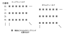
- FIG. 1A shows pixel sampling locations of a frame picture having two fields interlaced scanned.
- FIG. 1B shows pixel sampling positions of a field picture in which each interlaced scanned field is encoded as one field picture. If two complementary fields are encoded as one frame as shown in FIG. 1A, the frame has two picture order counts that represent the order of each field.
- FIG. 2 shows an example of an access unit with different picture coding structures for each viewpoint.
- access unit container A shown in module 200 has one frame picture of viewpoint 2 and one field picture of viewpoint 1 while access unit container B shown in module 202.
- the frame picture of the view 2 in the access unit A can not sufficiently use the inter-view prediction from the view 1 and the compression efficiency is reduced.
- each access unit container does not always have all the pictures (ie view components) of different views. Therefore, the size of each access unit can not be constrained by the limitations defined by the buffer model defined in the video standard to ensure proper encoding of the compressed video.
- Another problem of the prior art is the restriction set to limit the size of an access unit container having a picture with multiple views (that is, a view component defined in the MVC standard)
- a view component defined in the MVC standard There is Even though the maximum size of the access unit is limited, the maximum size of each picture of each view (that is, the view component defined in the MVC standard) in the access unit container is not restricted. Therefore, each viewpoint is different from H.
- decoding with the H.264 / MPEG-4 AVC decoder there may be problems with the implementation of the MVC decoder.
- constraints defined to limit the maximum size of the access unit ensure that each view component in the access unit is properly decoded when each view is decoded separately at the independent decoder It is not a thing.
- constraints include the maximum number of slices and the size of each picture in the access unit (ie, the view component defined in the MVC standard).
- the present invention has been made in view of the above circumstances, and provides an encoding method and a decoding method which improve the encoding efficiency of a plurality of image groups having different viewpoints, and an encoding apparatus and a decoding apparatus for realizing these. , Program, and integrated circuit.
- An encoding method encodes first and second image groups of an interlaced scheme captured from different viewpoints. Specifically, an access unit definition step of defining an access unit configured of mutually corresponding images in the first and second image groups, and for each of the access units defined in the access unit definition step, And an encoding step of encoding each image constituting the access unit.
- the access unit definition step includes a coding unit determination step of determining whether each image included in the access unit is to be encoded in a unit of field or a unit of frame, and each image included in the access unit And a field type determining step of determining whether to encode the respective images into a top field or a bottom field in a case where it is determined on a field basis. Then, in the encoding step, each image in the format determined in the encoding unit determination step and the field type determination step is encoded for each access unit.
- a value indicating whether the image is a field unit image or a frame unit image may be set in the reference field_pic_flag.
- a value indicating whether it is a top field or a bottom field may be set in the reference bottom_field_flag.
- the value of the reference field_pic_flag is set in the field_pic_flag included in the and the value indicating the field unit image is set in the reference field_pic_flag
- the value of the reference bottom_field_flag is included in the bottom_field_flag included in the slice header. It may be set.
- the encoding step further comprises a first encoding step of encoding an image belonging to the first image group using a predicted image generated from an image in the first image group; An image belonging to the second image group using a predicted image generated from an image in two image groups or a predicted image generated from an image belonging to the first image group included in the same access unit And a second encoding step of encoding. Since the formats of all the images included in the same access unit are unified, the coding efficiency is improved in the case of performing inter-view prediction coding in the second coding step.
- the coding method may include a step of checking the suitability of the coding process in the coding step.
- the compatibility check step includes a maximum slice number calculation step of calculating a maximum slice number of each image included in the access unit, and a maximum byte number calculation of calculating a maximum byte number of each image included in the access unit. Comparing the number of slices and the number of bytes of each image encoded in the encoding step with the corresponding maximum number of slices and the maximum number of bytes, and feeding back the comparison result to the encoding step And may be included. This makes it possible to prevent the output of a bit stream that can not be decoded.
- the quantization step may be increased or decreased based on the comparison result fed back from the comparison step. By increasing or decreasing the quantization step, the code amount can be adjusted.
- a decoding method decodes a coded stream obtained by coding first and second image groups having different viewpoints for each access unit configured with mutually corresponding images. Specifically, in the access unit, it is determined whether the image belonging to the first image group and the image belonging to the second image group are synchronized or not, and the judging step The decoding step includes performing different decoding processing depending on whether it is determined that the synchronization is achieved or not.
- the decoding process is performed after confirming the presence or absence of synchronization, it is possible to effectively prevent the inter-view prediction decoding process from being performed based on, for example, a predicted image different from the original predicted image. .
- the slice header of each image included in the access unit includes the field_pic_flag and the bottom_field_flag described above. Then, in the determination step, the values of the field_pic_flag included in the slice header of the image belonging to the first image group and the image belonging to the second image group match, and the field_pic_flag is an image in units of fields. Synchronization is achieved by matching the value of the bottom_field_flag included in the slice header of the image belonging to the first image group and the image belonging to the second image group, when the value indicating that is set. It may be determined that
- the decoding step includes: a first decoding step of decoding an image belonging to the first image group using a predicted image generated from an image in the first image group; and the second image The image belonging to the second image group is decoded using a predicted image generated from an image in a group or a predicted image generated from an image belonging to the first image group included in the same access unit And a second decoding step. Then, in the second decoding step, when it is determined in the determination step that synchronization is not achieved, an image included in the first image group included in the same access unit may be output. .
- the inter-view prediction decoding process can not be performed. Therefore, the decoding process is stopped, and the corresponding image decoded normally is output. As a result, it is possible to solve the problem that an unnatural image is displayed although it is temporarily a two-dimensional image.
- An encoding apparatus encodes first and second image groups of an interlaced scheme captured from different viewpoints.
- an access unit definition unit that defines an access unit configured by mutually corresponding images in the first and second image groups, and for each of the access units defined by the access unit definition unit, And an encoding unit configured to encode each image constituting the access unit.
- the access unit definition unit determines a coding unit determination unit that determines whether each image included in the access unit is to be encoded in a unit of field or a unit of frame, and each image included in the access unit And a field type determination unit that determines whether to encode each of the images into a top field or a bottom field in a case where it is determined on a field basis. Then, the encoding unit encodes each image of the format determined in the encoding unit determination step and the field type determination step for each access unit.
- a decoding apparatus decodes a coded stream obtained by coding first and second image groups having different viewpoints for each access unit configured with mutually corresponding images. Specifically, in the access unit, a determination unit that determines whether an image belonging to the first image group and an image belonging to the second image group are synchronized, and the determination unit And a decoding unit that executes different decoding processing depending on whether it is determined that synchronization is achieved or not.
- a program causes a computer to encode interlaced first and second image groups captured from different viewpoints. Specifically, an access unit definition step of defining an access unit configured of mutually corresponding images in the first and second image groups, and for each of the access units defined in the access unit definition step, And an encoding step of encoding each image constituting the access unit.
- the access unit definition step includes a coding unit determination step of determining whether each image included in the access unit is to be encoded in a unit of field or a unit of frame, and each image included in the access unit And a field type determining step of determining whether to encode the respective images into a top field or a bottom field in a case where it is determined on a field basis. Then, in the encoding step, each image in the format determined in the encoding unit determination step and the field type determination step is encoded for each access unit.
- a program causes a computer to decode an encoded stream obtained by encoding first and second image groups having different viewpoints for each access unit configured with mutually corresponding images. . Specifically, in the access unit, it is determined whether the image belonging to the first image group and the image belonging to the second image group are synchronized or not, and the judging step The decoding step includes performing different decoding processing depending on whether it is determined that the synchronization is achieved or not.
- An integrated circuit encodes interlaced first and second image groups captured from different viewpoints.
- an access unit definition unit that defines an access unit configured by mutually corresponding images in the first and second image groups, and for each of the access units defined by the access unit definition unit, And an encoding unit configured to encode each image constituting the access unit.
- the access unit definition unit determines a coding unit determination unit that determines whether each image included in the access unit is to be encoded in a unit of field or a unit of frame, and each image included in the access unit And a field type determination unit that determines whether to encode each of the images into a top field or a bottom field in a case where it is determined on a field basis. Then, the encoding unit encodes each image of the format determined in the encoding unit determination step and the field type determination step for each access unit.
- An integrated circuit decodes a coded stream obtained by coding first and second image groups having different viewpoints for each access unit configured with mutually corresponding images. Specifically, in the access unit, a determination unit that determines whether an image belonging to the first image group and an image belonging to the second image group are synchronized, and the determination unit And a decoding unit that executes different decoding processing depending on whether it is determined that synchronization is achieved or not.
- FIG. 1A shows an example of a frame picture.
- FIG. 1B shows an example of a field picture.
- FIG. 2 shows an example of an access unit with different picture coding structures for each viewpoint.
- FIG. 3 is an example showing a data structure of an access unit.
- FIG. 4 is a functional block diagram of the coding apparatus according to Embodiment 1 of the present invention.
- FIG. 5 is a functional block diagram of a view component coding unit.
- FIG. 6 is a functional block diagram of the compatibility check unit.
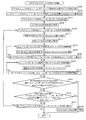
- FIG. 7 is a flowchart showing the entire process of encoding an MVC access unit.
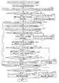
- FIG. 8 is a flowchart illustrating encoding processing of view components of the MVC access unit.
- FIG. 9 is a flowchart showing a process of determining the compatibility of the MVC access unit.
- FIG. 10 is a functional block diagram of a decoding apparatus according to Embodiment 1 of the present invention.
- FIG. 11 is a diagram showing a modification of the decoding apparatus shown in FIG.
- FIG. 12 is a flowchart showing decoding processing of a view component of the MVC access unit.
- FIG. 13 is a schematic view showing an example of the entire configuration of the content supply system for realizing the content distribution service.
- FIG. 14 is a view showing the appearance of a mobile phone.
- FIG. 15 is a block diagram showing a configuration example of a mobile phone.
- FIG. 16 is a schematic view showing an example of the entire configuration of the digital broadcasting system.
- FIG. 17 is a block diagram showing a configuration example of a television.
- FIG. 18 is a block diagram showing a configuration example of an information reproduction and recording unit that reads and writes information on a recording medium which is an optical disk.
- FIG. 19 is a view showing an example of the structure of a recording medium which is an optical disc.
- FIG. 20 is a block diagram showing a configuration example of an integrated circuit for realizing the image coding method and the image decoding method according to each embodiment.
- a new method is introduced that constrains the picture coding structure (frame / field picture coding) and the data size of each picture in the access unit (that is, the view component defined in the MVC standard).
- the novelty of the present invention is that each viewpoint is an existing H.264.
- the method of decoding separately using the H.264 / MPEG-4 AVC decoder is to ensure successful decoding of the video stream compressed using the MVC standard.
- This new invention adds constraints to the data size and the value of the specific syntax of each picture in the access unit (ie, the view component defined in the MVC standard).
- An advantage of the invention is the low cost implementation of the MVC standard encoders and decoders.
- the present invention also helps to improve coding efficiency as "inter-view" prediction is available between field pictures of each view.
- the present invention includes two main processes: encoding process of view component of access unit and decoding process of view component of access unit.
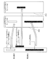
- the present invention limits the values of the syntax in the slice header shown in FIG. 3, that is, the values of field_pic_flag and bottom_field_flag, in the slice header to be the same among all view components in the same access unit, in order to solve the problems described above.
- the field_pic_flag of FIG. 3 is used to determine whether the slice associated with the view component is encoded as a field or as a frame. For example, if the value of field_pic_flag is "1", it indicates that the slice belongs to a view component encoded as one field, and if the value is "0", the slice is encoded as a frame. Indicates that it belongs to a view component.
- the bottom_field_flag of FIG. 3 is used to determine whether the slice associated with the view component encoded as a field is a top field or a bottom field. Whether or not bottom_field_flag is present in the slice header depends on the value of field_pic_flag. For example, if the value of bottom_field_flag is “1”, it indicates that the slice belonging to the view component encoded as a field is a bottom field, and if the value of bottom_field_flag is “0”, it is encoded as a field Indicates that the slice belonging to the view component is the top field. However, when “0” is set in the field_pic_flag of the slice header output from the encoding apparatus, the bottom_field_flag of the slice header is omitted.
- the invention also limits the total number of slices and the total number of bytes of each view component in the access unit.
- FIG. 4 is a functional block diagram of the coding apparatus 10 according to Embodiment 1 of the present invention.
- the encoding apparatus 10 is an apparatus for encoding an image of a viewpoint 1 and an image of a viewpoint 2 and includes an access unit definition unit 20 and a view component encoding unit 800 as shown in FIG. 4.
- the image of the viewpoint 1 is a moving image (first image group) of an interlace method in which an object is captured from a first viewpoint.
- the image of the viewpoint 2 is a moving image (second image group) of the interlace method in which the same object is captured from a second viewpoint different from the first viewpoint.
- the access unit definition unit 20 includes an encoding unit determination unit 30 and a field type determination unit 40, and defines an access unit composed of images corresponding to each other of the viewpoint 1 and the viewpoint 2.
- the “corresponding image” refers to, for example, an image captured at the same time, and the same PTS (Presentation Time Stamp) is added. Alternatively, the corresponding pictures are given the same picture order count.
- the coding unit determination unit 30 determines whether each image included in the access unit is to be encoded in a unit of field or a unit of frame. More specifically, the coding unit determination unit 30 sets “0” to the reference field_pic_flag, which is an internal variable, when unifying the images included in the access unit in frame units. On the other hand, when making it unify to a field unit, "1" is set to reference field_pic_flag.
- the field type determination unit 40 determines whether the images are to be unified into the top field or the bottom field and encoded. More specifically, when unifying the images included in the access unit into the top field, the field type determination unit 40 sets “0” to the reference bottom_field_flag which is an internal variable. On the other hand, in the case of unifying to the bottom field, the reference bottom_field_flag is set to “1”. However, this process is performed only when “1” is set in the reference field_pic_flag, and when “0” is set in the reference field_pic_flag, “0” is automatically set in the reference bottom_field_flag.
- the view component encoding unit 800 encodes, for each access unit defined by the access unit definition unit 20, each image of the format determined by the encoding unit determination unit 30 and the field type determination unit 40.
- FIG. 5 is a functional block diagram of the view component coding unit 800.
- the view component coding unit 800 includes first and second view component coding units 900 and 904, and a storage unit 902. However, as a modification of the view component coding unit 800, the first and second view component coding units 800 and 900 may be integrated.
- the first view component coding unit 900 reads out the image D 001 of the viewpoint 1.
- the format of the image D001 read out at this time is either field unit or frame unit based on the determination contents of the coding unit determination unit 30 and the field type determination unit 40, and further (in the case of field unit) the top field or It is determined to be one of the bottom fields.
- the first view component coding unit 900 codes the read image D 001 in slice units. For example, the first view component coding unit 900 subtracts the predicted image of the image D001 from the image D001, performs orthogonal transform (DCT transform), quantizes, and performs entropy coding to obtain the encoded view component D005 of the viewpoint 1 obtained. Is output to Vout. At this time, the predicted image of the image D 001 is generated (in-screen prediction or inter-screen prediction) using the already encoded image of the images of the viewpoint 1. That is, the viewpoint 1 in the first embodiment is the “Base view” which does not depend on other viewpoints (in this example, the viewpoint 2).
- DCT transform orthogonal transform
- the first view component coding unit 900 performs inverse quantization on the quantization coefficient obtained by quantization, performs inverse orthogonal transform, and outputs a reconstructed image D 003 obtained by adding the predicted image to the storage unit 902. Do. Furthermore, the first view component coding unit 900 outputs the value of bottom_field_flag and the value of field_pic_flag used for coding the coding view component D 005 to the second view component coding unit 904.
- the second view component encoding unit 904 reads out the image D002 of viewpoint 2 included in the same access unit as the image D001 of viewpoint 1.
- the format of the image D002 read out at this time is either field unit or frame unit, or further (in the case of field unit, based on the value of bottom_field_flag and the value of field_pic_flag acquired from the first view component encoding unit 900). ) Determined as either top field or bottom field. That is, the image D001 and the image D002 have the same format.
- the second view component encoding unit 904 encodes the read image D002 in units of slices, and outputs the encoded view component D007 to Vout.
- the specific encoding process is the same as that of the first view component encoding unit 900
- the predicted image of the image D002 is generated using the already encoded image of the images of viewpoint 2 (in-screen prediction Alternatively, inter-screen prediction may be performed, or generation (inter-view prediction) may be performed using an image of viewpoint 1 (that is, a reconstructed image D003 of image D001) included in the same access unit. This is different from the view component coding unit 900 of FIG.
- the encoding device 10 according to Embodiment 1 may further include the compatibility check unit 815.
- FIG. 6 is a functional block diagram of the compatibility check unit 815.
- Conformance check unit 815 includes slice number calculation unit 804, byte number calculation unit 802, maximum slice number calculation unit 806, comparison units 808 and 812, maximum byte number calculation unit 810, and switching unit 814. .
- the conformance check unit 815 analyzes the result of the encoding process performed by the view component encoding unit 800, and feeds back the analysis result to the view component encoding unit 800.
- the view component coding unit 800 outputs the coding view component D 005 of the viewpoint 1 to the slice number calculation unit 804, the byte number calculation unit 802, and the switching unit 814.
- the process for the encoded view component D 007 of the viewpoint 2 is also the same, so in the following description, the process for the encoded view component D 005 of the viewpoint 1 will be mainly described.
- the slice number calculation unit 804 outputs the acquired total number D011 of slices in the encoded view component D005 to the comparison unit 808.
- the number-of-bytes calculation unit 802 outputs the obtained total number of bytes D012 in the encoded view component D005 to the comparison unit 812.
- the maximum slice number calculation unit 806 outputs the maximum slice number D 014 for each view component to the comparison unit 808 based on the acquired profile information and level information input D 013.
- the method of determining the maximum number of slices D014 for each view component is not particularly limited, for example, the maximum number of slices of the image belonging to the viewpoint 1 which is "Base view” is relatively increased, and the viewpoint 2 which is “Dependent view” The maximum number of slices of the belonging image may be relatively reduced.
- the maximum byte number calculation unit 810 outputs the maximum byte number D015 for each view component to the comparison unit 808 based on the acquired profile information and level information input D013.
- the method of determining the maximum number of bytes D015 for each view component is not particularly limited, for example, the maximum number of bytes of the image belonging to the viewpoint 1 which is "Base view” is relatively increased, and the viewpoint 2 which is “Dependent view” The maximum number of bytes of the belonging image may be relatively reduced.
- the comparison unit 808 compares the total number of slices D011 with the maximum number of slices D014. Then, if the total number of slices D011 is equal to or less than the maximum number of slices D014, it is determined that the encoding process conforms to a predetermined condition, and the valid signal D016 is output to the switching unit 814. On the other hand, if the total number of slices D011 is larger than the maximum number of slices D014, the comparison unit 808 determines that the encoding process does not meet the predetermined condition, and outputs the control signal D017 to the view component encoding unit 800.
- the comparison unit 812 compares the total number of bytes D012 with the maximum number of bytes D015. Then, if the total byte count D012 is equal to or less than the value of the maximum byte count D015, it is determined that the encoding processing conforms to a predetermined condition, and the valid signal D018 is output to the switching unit 814. On the other hand, if the total number of bytes D012 is larger than the maximum number of bytes D015, the comparison unit 812 determines that the encoding process does not meet the predetermined condition, and outputs the control signal D019 to the view component encoding unit 800.
- the view component encoding unit 800 re-encodes the same input image when any of the control signals D017 and D019 is received.
- the encoding process is performed using, for example, a quantization step larger than the quantization step used in the previous encoding process, in order to conform to a predetermined condition.
- the switching unit 814 is enabled when both of the enabling signals D016 and D018 are received from the comparing units 808 and 812, and outputs the encoded view component D005 to Vout. When not received, the switching unit 814 does not output the encoded view component D 005 to Vout.
- the view component coding unit 800 may output the coded view component D005 in units of pictures at the timing when all coding of the image D001 is completed. However, if it is found that the image D001 does not meet the predetermined conditions after the encoding of the image D001 is complete, the same image D001 needs to be re-encoded under different conditions (such as changing the quantization step). The processing load of the view component coding unit 800 is increased.
- the view component coding unit 800 may output the slice view of the coding view component D 005 at the timing when the coding of each slice constituting the image D 001 is completed. Also, the number-of-bytes calculation unit 802 may output the total number of bytes D012 of the encoded view component D005 encoded up to now to the comparison unit 812 one by one.
- the comparison unit 812 can predict in advance the possibility that the total number of bytes D012 exceeds the maximum number of bytes D015, and can transmit the control signal D019 to the view component encoding unit 800. Then, based on the control signal D019, the view component encoding unit 800 can make the encoding process conform to a predetermined condition by, for example, enlarging the quantization step during the encoding of the image D001. .
- FIG. 7 is a flowchart showing the entire process of encoding an access unit using the MVC standard.
- the view component coding unit 800 first codes all view components in the access unit (S700).
- the conformance check unit 815 verifies the conformance of the access unit by determining the value of the parameter ConformanceFlag (S702). Does ConformanceFlag be less than or equal to the maximum value allowed for normal decoding of view components in the access unit by the typical decoder of the MVC standard, and the total number of slices in all view components and the total number of bytes in all access units? It is used to indicate whether or not.
- ConformanceFlag Does ConformanceFlag be less than or equal to the maximum value allowed for normal decoding of view components in the access unit by the typical decoder of the MVC standard, and the total number of slices in all view components and the total number of bytes in all access units? It is used to indicate whether or not.
- the conformance check unit 815 determines the total number of slices in all view components and all of them.
- the view component coding unit 800 views the access unit in such a way that the total number of bytes in the access unit in the access unit is less than or equal to the maximum value allowed for normal decoding of the view component in the access unit by the normal decoder of the MVC standard.
- the component is re-encoded to reduce either the total number of slices or the total number of bytes in the view component (S706).
- the view component encoding unit 800 when the ConformanceFlag of the view component belonging to "Base view” becomes “0", the view component encoding unit 800 has already encoded among the other view components belonging to "Base view”. An encoded view component may be output. It is desirable that the coding view component selected at this time be immediately before (in order of reproduction time) the view component for which coding has failed (conformance violation). On the other hand, when the ConformanceFlag of a view component belonging to "Dependent view” becomes “0", view component encoding section 800 outputs an encoded view component belonging to "Base view” included in the same access unit. Good.
- FIG. 8 is a flowchart showing an encoding process of view components of the access unit.
- the coding unit determination unit 30 determines the value of the reference field_pic_flag (S502).
- the method of determining the reference field_pic_flag is not particularly limited, and any conventional method can be used.
- the field type determination unit 40 compares the value of the reference field_pic_flag with "0" (S504). If the value of field_pic_flag is equal to "0" (Yes in S504), the field type determination unit 40 sets the reference bottom_field_flag to "0" (S506). On the other hand, if the value of field_pic_flag is not equal to “0” (S504: No), field type determination unit 40 determines the value of reference bottom_field_flag (S508).
- the determination method of reference bottom_field_flag is not specifically limited, All the conventional methods can be used.
- the reference field_pic_flag is later used to set the values of all field_pic_flags of slices in the same access unit. Also, the reference bottom_field_flag is later used to set the value of all bottom_field_flag of the slice in the same access unit.
- the access unit definition unit 20 refers to the value of field_pic_flag in the slice header of all slices for all slices (S512 to S528) in all view components (S510 to S530) of the same access unit. It is set to a value equal to the value of field_pic_flag (S514).
- the access unit definition unit 20 sets the value of bottom_field_flag in the slice header of all slices in the same access unit to the value of reference bottom_field_flag. (S520). On the other hand, if the value of field_pic_flag is not equal to "1" (No in S516), access unit definition unit 20 sets the value of bottom_field_flag in the slice header of all slices in the same access unit to "0". (S518). Note that S516 and S518 may be omitted, and the value of bottom_field_flag in the slice header of all slices in the same access unit may be set as the value of reference bottom_field_flag.
- the view component coding unit 800 executes coding of all slices in the same access unit based on the value of field_pic_flag and the value of bottom_field_flag (S526).
- the details of the encoding process of the view component encoding unit 800 are as described with reference to FIG.
- FIG. 9 is a flow chart showing the compatibility confirmation process of the access unit. This process can also be applied to the conformance check of view components in the access unit.
- the maximum number-of-slices calculation unit 806 determines the maximum number of slices D014 permitted for each view component in one access unit (S600).
- the allowable maximum number of slices D014 is calculated based on the profile information indicated by the syntax element transmitted by the compressed stream associated with the access unit and the limit defined by the level information D013.
- Such syntax elements are, for example, profile_idc syntax and level_idc syntax in the sequence parameter set of the MVC encoded stream.
- the maximum number of bytes calculating unit 810 determines the maximum number of bytes D015 allowed for each view component in one access unit (S602).
- the allowable maximum number of bytes D015 is calculated based on the profile information indicated by the syntax element transmitted by the encoded video stream associated with the access unit and the restriction defined by the level information D013.
- the compatibility check unit 815 determines the number of view components in one access unit (S604). Then, the conformance check unit 815 sets the parameter ConformanceFlag to "1" (S608). This parameter ConformanceFlag is a requirement for view components in the access unit to be correctly decoded by the video decoder by associating profile values and level values higher than the specified profile value and level value in the encoded video stream. It is used to determine if it is satisfied.
- the byte number calculation unit 802 initializes the parameter NumBytesInViewComponent to “0” (S612).
- the slice number calculation unit 804 also initializes the parameter NumOfSlices to “0” (S614).
- the parameter NumBytesInViewComponent is a counter that counts the total number of bytes D012 in the view component.
- the parameter NumOfSlices is a counter that counts the total number of slices D011 in the view component.
- the number-of-bytes calculation unit 802 adds the total number of bytes represented by the parameter NumBytesInNALUnit to the parameter NumBytesInViewComponent (S618). That is, the parameter NumBytesInViewComponent has a value equal to the sum of the parameters NumBytesInNALUnit associated with that view component.
- the NAL unit is based on H. It is defined as a network abstraction layer defined in the H.264 / MPEG-4 AVC standard, and has encoded video data.
- the slice number calculation unit 804 increments the parameter NumOfSlices by one (S624). That is, the parameter NumOfSlices has a value equal to the total number of slices associated with the same view component.
- the comparison units 808 and 812 compare the values of the parameter NumBytesInViewComponent and the parameter NumOfSlices with the maximum number of bytes D015 and the maximum number of slices D014 allowed in one view component (S628, S630).
- the comparison unit 812 sets the parameter ConformanceFlag to “0” (S634). If the value of NumOfSlices is larger than the allowable maximum number of slices D014 (Yes in S630), the comparison unit 808 sets the parameter ConformanceFlag to “0” (S634).
- the parameter ConformanceFlag is set to “0” because the view component in the access unit associates the profile value and level value higher than the specified profile value and level value in the encoded video stream and the video decoder Indicates that it may not be decoded correctly.
- FIG. 10 is a functional block diagram of the decoding device 50 according to Embodiment 1 of the present invention.
- the decoding device 50 includes a view component distribution unit 1000, first and second slice header analysis units 1002 and 1004, a comparison unit 1006, a switching unit 1010, and first and second.
- the A-type view component decoding units 1008 and 1014, the B-type view component decoding unit 1016, and the storage unit 1012 are provided.
- the view component distribution unit 1000 reads the coding access unit D021 and distributes it to two first and second view components D023 and D022.
- the first view component D 023 is an image belonging to viewpoint 1 (Base view) which does not depend on the second view component D 022 when correctly reconstructing the image.
- the second view component D022 is an image belonging to the viewpoint 2 (Dependent view) depending on the first view component D023 when correctly reconstructing the image.
- the first slice header analysis unit 1002 reads the first view component D 023, and outputs bottom_field_flag and field_pic_flag information D 025 to the comparison unit 1006.
- the second slice header analysis unit 1004 reads the second view component D 022, and outputs bottom_field_flag and field_pic_flag information D 026 to the comparison unit 1006.
- the comparison unit 1006 compares the information D025 values of the bottom_field_flag and the field_pic_flag from the first slice header analysis unit 1002 with the information D026 of the bottom_field_flag and the field_pic_flag from the second slice header analysis unit 1004, and controls the comparison result Signal D 027 is output to switching unit 1010.
- the comparison unit 1006 is a determination unit that determines whether or not the first view component D023 belonging to the viewpoint 1 and the second view component D022 belonging to the viewpoint 2 are synchronized in the same access unit. Function. That is, if the values of the bottom_field_flag and the field_pic_flag of the first and second view components D023 and D022 match, the comparison unit 1006 determines that the two are synchronized. On the other hand, if at least one of these values does not match, the comparison unit 1006 determines that synchronization is not achieved.
- the parameter for determining whether or not synchronization is established is not limited to the above example. For example, if the PTS (Presentation Time Stamp) and the DTS (Decoding Time Stamp) held by the first and second view components D023 and D022 match, synchronization is achieved if they do not match. You may decide that you have not taken it.
- PTS Presentation Time Stamp
- DTS Decoding Time Stamp
- the first A-type view component decoding unit 1008 reads the first view component D 023 and outputs an image D 031 of the viewpoint 1. Further, the first A-type view component decoding unit 1008 outputs the reconstructed image D 031 of the viewpoint 1 to the storage unit 1012. Specifically, the first A-type view component decoding unit 1008 entropy-decodes the first view component D 023, inversely quantizes it, performs inverse orthogonal transformation, and adds a predicted image to reconstruct an image D 031. Output.
- the first view component D 023 belongs to “Base view”, the predicted image is generated (in-screen prediction or inter-screen prediction) using the already decoded image of the images of viewpoint 1. .
- the switching unit 1010 outputs the second view component D 022 to either the second A-type view component decoding unit 1014 or the B-type view component decoding unit 1016 based on the control signal D 027 acquired from the comparison unit 1006. Do. Specifically, when the first and second view components D 023 and D 022 are synchronized, the switching unit 1010 outputs the second view component D 022 to the second A-type view component decoding unit 1014. . On the other hand, when the two are not synchronized, the second view component D 022 is output to the B-type view component decoding unit 1016.
- the second A-type view component decoding unit 1014 When the second A-type view component decoding unit 1014 receives the second view component D022, the second A-type view component decoding unit 1014 decodes the second view component D022 using the reconstructed image D031 of the viewpoint 1 read from the storage unit 1012 Image of the viewpoint 2 is output.
- the specific encoding process is the same as that of the first A-type view component decoding unit 1008, but a predicted image is generated using an already decoded image of the images of viewpoint 2 (in-screen prediction or screen Inter-prediction, or the first A-type view component decoding in that it may be generated (inter-view prediction) using an image of viewpoint 1 (that is, image D031) included in the same access unit. It differs from part 1008.
- the B-type view component decoding unit 1016 When receiving the second view component D022, the B-type view component decoding unit 1016 outputs an image D035 of viewpoint 2.
- the case where the decoding process is executed by the B-type view component decoding unit 1016 is a case where the first and second view components D 023 and D 022 are not synchronized, so decoding using at least “inter-view prediction” It is considered impossible to process. Therefore, when the second view component D 022 is a coded object using “inter-view prediction” and is an object, the B-type view component decoding unit 1016 collectively stores the decoding processing and is stored in the storage unit 1012.
- the existing image D 031 is output as the image D 035 of the viewpoint 2 and encoded using “in-screen prediction” or “inter-frame prediction”
- normal decoding processing may be performed.
- the image D031 stored in the storage unit 1012 may be output as the image D035 of the viewpoint 2 regardless of the type of prediction.
- decoding devices may not have the B-type view component decoding unit 1016.
- FIG. 11 is a functional block diagram of a decoding device 60 which is a modification of the decoding device 50.
- the decoding device 60 includes a field view component distribution unit 1100, first and second field view component decoding units 1102 and 1104, and a storage unit 1106.
- the field view component distributor 1100 reads out the coded access unit D041 and distributes it to the first and second view components D044, D042. Then, the field view component distribution unit 1100 outputs the first view component D 044 to the first field view component decoding unit 1102 and the second view component D 042 to the second field view component decoding unit 1104.
- the first view component D 044 is an image belonging to the viewpoint 1 (Base view) which does not depend on the second view component D 042 when the image is correctly reconstructed.
- the second view component D042 is an image belonging to the viewpoint 2 (Dependent view) which depends on the first view component D044 when correctly reconstructing the image.
- the view components D042 and D044 may be single field pictures.
- the first field view component decoding unit 1102 decodes the field-based first view component D 044 belonging to the acquired viewpoint 1 and outputs an image D 051 of the viewpoint 1. Further, the reconstructed image D 051 of the viewpoint 1 is also stored in the storage unit 1106.
- the storage unit 1106 includes a memory buffer for storing the reconstructed image D051 of the viewpoint 1 output from the first field view component decoding unit 1102.
- the second field view component decoding unit 1104 decodes the second view component D042 of the field unit belonging to the acquired viewpoint 2 using the reconstructed image D051 of the viewpoint 1 acquired from the storage unit 1106, The two reconstructed images D054 are output.
- FIG. 12 is a flowchart showing the decoding process of the view component of the access unit.
- the comparison unit 1006 sets “0” to the parameter SpecialDecodingFlag (S400).
- This SpecialDecodingFlag uses the normal decoding process defined in the MVC standard for the decoding process of all the second view components D022 in the access unit, or for the decoding of some view components in the access unit. It is used to decide whether to use a different decoding process. That is, it corresponds to the control signal D027 shown in FIG.
- the first slice header analysis unit 1002 determines the value of the reference field_pic_flag from the slice header of one slice of the first view component D 023 belonging to "Base view” (S402).
- the value of this reference field_pic_flag is later used to compare with the value of field_pic_flag in the slice header of other view components.
- the first slice header analysis unit 1002 extracts the value of reference bottom_pic_flag from the slice header of one slice of the first view component D023. It decides (S408). On the other hand, if the value of the field_pic_flag is equal to “0” (Yes in S404), the first slice header analysis unit 1002 sets “0” to the value of the reference bottom_pic_flag (S406). The value of this reference bottom_pic_flag is later used to compare with the value of bottom_pic_flag in the slice header of other view components.
- the second slice header analysis unit 1004 determines the value of field_pic_flag from the slice header of the slice (S414). If the value of field_pic_flag is not equal to “0” (No in S416), the second slice header analysis unit 1004 determines the value of bottom_pic_flag from the slice header of the slice (S420). On the other hand, if the value of field_pic_flag is equal to "0" (Yes in S416), the second slice header analysis unit 1004 sets "0" to the value of bottom_field_flag (S418).
- the comparison unit 1006 compares the values of field_pic_flag and bottom_field_flag acquired from the second slice header analysis unit 1004 with the values of reference field_pic_flag and reference bottom_field_flag acquired from the first slice header analysis unit 1002 (S422, S 426).
- the comparison unit 1006 sets “1” in the parameter SpecialDecodingFlag (S432). Similarly, if the value of bottom_field_flag is not equal to the value of reference bottom_field_flag (No in S428), the comparison unit 1006 sets “1” in the parameter SpecialDecodingFlag (S432). Then, the comparison unit 1006 outputs the value of the parameter SpecialDecodingFlag (that is, the control signal D027) to the switching unit 1010.
- the switching unit 1010 compares the parameter SpecialDecodingFlag with “1” (S438). If this parameter SpecialDecodingFlag is not equal to “1” (S438: No), all view components in the access unit are decoded by the decoding process defined in the MVC standard (S440). On the other hand, if SpecialDecodingFlag is equal to "1" (Yes in S438), the view component belonging to "Dependent view” in the access unit is decoded by a decoding process different from the above (S442).
- An example of a different decoding process is to correctly reconstruct only one view component in the access unit from the video decoder.
- the present invention can also be used when encoding moving images captured from two or more different viewpoints.
- the storage medium may be a magnetic disk, an optical disk, a magneto-optical disk, an IC card, a semiconductor memory, or the like as long as the program can be recorded.
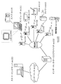
- FIG. 13 is a diagram showing an overall configuration of a content supply system ex100 for realizing content distribution service.
- the area for providing communication service is divided into desired sizes, and base stations ex106 to ex110, which are fixed wireless stations, are installed in each cell.
- This content supply system ex100 includes a computer ex111, a personal digital assistant (PDA) ex112, a camera ex113, a mobile phone ex114, and a game machine via the Internet ex101, the Internet service provider ex102 and the telephone network ex104, and the base stations ex106 to ex110. Each device such as ex115 is connected.
- PDA personal digital assistant
- each device may be directly connected to the telephone network ex104 without passing through the base stations ex106 to ex110, which are fixed wireless stations.
- the devices may be directly connected to each other via near field communication or the like.
- the camera ex113 is a device capable of shooting moving images such as a digital video camera
- the camera ex116 is a device capable of shooting still images and moving images such as a digital camera.
- the mobile phone ex114 is a GSM (Global System for Mobile Communications) system, a CDMA (Code Division Multiple Access) system, a W-CDMA (Wideband-Code Division Multiple Access) system, or an LTE (Long Term Evolution) system, HSPA ( It may be a High Speed Packet Access mobile phone, a PHS (Personal Handyphone System), or the like.
- live distribution and the like become possible by connecting the camera ex113 and the like to the streaming server ex103 through the base station ex109 and the telephone network ex104.
- live distribution encoding processing is performed on content (for example, video of music live, etc.) captured by the user using the camera ex113 as described in the above embodiment, and the encoded content is transmitted to the streaming server ex103.
- the streaming server ex 103 streams the content data transmitted to the requested client.
- the clients include the computer ex111, the PDA ex112, the camera ex113, the mobile phone ex114, the game machine ex115 and the like capable of decoding the above-mentioned encoded data.
- Each device that has received the distributed data decrypts and reproduces the received data.
- encoding processing of captured data may be performed by the camera ex 113, may be performed by the streaming server ex 103 that performs data transmission processing, or may be performed sharing each other.
- the decryption processing of similarly distributed data may be performed by the client, may be performed by the streaming server ex 103, or may be performed sharing each other.
- not only the camera ex113 but also still images and / or moving image data captured by the camera ex116 may be transmitted to the streaming server ex103 via the computer ex111.
- the encoding process in this case may be performed by any of the camera ex 116, the computer ex 111, and the streaming server ex 103, or may be performed sharing each other.
- the encoding process and the decoding process are generally performed by a computer ex 111 and a large scale integration (LSI) ex 500 included in each device.
- the LSI ex 500 may be a single chip or a plurality of chips.
- Software for image coding and image decoding is incorporated in any recording medium (CD-ROM, flexible disk, hard disk, etc.) readable by computer ex111 etc., and the coding process and decoding process are performed using the software. May be Furthermore, when the mobile phone ex114 is equipped with a camera, moving image data acquired by the camera may be transmitted. The moving image data at this time is data encoded by the LSI ex 500 included in the mobile phone ex 114.
- the streaming server ex103 may be a plurality of servers or a plurality of computers, and may process, record, or distribute data in a distributed manner.
- the client can receive and reproduce the encoded data.
- the client can receive, decode, and reproduce the information transmitted by the user in real time, and even a user who does not have special rights or facilities can realize personal broadcasting.
- the image encoding method or the image decoding method described in the above embodiment may be used for encoding and decoding of each device constituting the content supply system.
- the mobile phone ex114 will be described as an example.
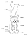
- FIG. 14 is a diagram showing a cellular phone ex114 using the image coding method and the image decoding method described in the above embodiment.
- the cellular phone ex114 is an antenna ex601 for transmitting and receiving radio waves to and from the base station ex110, a video such as a CCD camera, a camera unit ex603 capable of taking a still image, a video shot with the camera unit ex603, and the antenna ex601.
- a display unit ex602 such as a liquid crystal display for displaying data obtained by decoding a received video or the like, a main body unit including operation keys ex604, an audio output unit ex608 such as a speaker for audio output, and audio input Audio input unit ex605 such as microphone, captured moving image or still image data, received mail data, moving image data or still image data, etc., for recording encoded data or decoded data
- Media ex 607, recording media ex 607 can be attached to mobile phone ex 114 And a slot unit ex606 for.
- the recording medium ex 607 stores a flash memory element, which is a type of EEPROM, which is a nonvolatile memory that can be electrically rewritten and erased, in a plastic case such as an SD card.
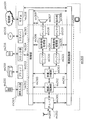
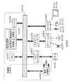
- a mobile phone ex114 is provided with a power control circuit ex710, an operation input control unit ex704, an image encoding, and a main control unit ex711 that is configured to integrally control each unit of the main unit including the display unit ex602 and the operation key ex604.
- Unit ex712, camera interface unit ex703, LCD (Liquid Crystal Display) control unit ex702, image decoding unit ex709, demultiplexing unit ex708, recording / reproduction unit ex707, modulation / demodulation circuit unit ex706, and audio processing unit ex705 are mutually connected via synchronization bus ex713 It is connected.
- the power supply circuit unit ex710 activates the camera-equipped digital mobile phone ex114 to an operable state by supplying power from the battery pack to each unit when the end of the call and the power key are turned on by the operation of the user. .
- the mobile phone ex114 converts the audio signal collected by the audio input unit ex605 into digital audio data by the audio processing unit ex705 based on the control of the main control unit ex711 including CPU, ROM, RAM, etc. This is spread spectrum processing in the modulation / demodulation circuit unit ex706, subjected to digital / analog conversion processing and frequency conversion processing in the transmission / reception circuit unit ex701, and then transmitted through the antenna ex601.
- the cellular phone ex114 amplifies the reception data received by the antenna ex601, performs frequency conversion processing and analog-to-digital conversion processing, performs spectrum despreading processing in the modulation / demodulation circuit unit ex706, and performs analog sound processing in the sound processing unit ex705. After conversion into data, the data is output via the audio output unit ex 608.
- text data of the electronic mail input by the operation of the operation key ex604 of the main unit is sent to the main control unit ex711 via the operation input control unit ex704.
- the main control unit ex711 performs spread spectrum processing on the text data in the modulation / demodulation circuit unit ex706, performs digital / analog conversion processing and frequency conversion processing in the transmission / reception circuit unit ex701, and transmits the data to the base station ex110 via the antenna ex601.
- the image data captured by the camera unit ex603 is supplied to the image coding unit ex712 via the camera interface unit ex703.
- the image data captured by the camera unit ex603 can be directly displayed on the display unit ex602 via the camera interface unit ex703 and the LCD control unit ex702.
- the image coding unit ex712 is configured to include the image coding apparatus described in the present invention, and uses the image data supplied from the camera unit ex603 for the image coding apparatus shown in the above embodiment.
- the compression image data is converted into encoded image data by compression coding, and this is sent to the demultiplexing unit ex 708.
- the cellular phone ex114 simultaneously transmits the sound collected by the audio input unit ex605 during imaging by the camera unit ex603 to the demultiplexing unit ex708 as digital audio data via the audio processing unit ex705.
- the demultiplexing unit ex708 multiplexes the encoded image data supplied from the image coding unit ex712 and the audio data supplied from the audio processing unit ex705 according to a predetermined method, and the multiplexed data obtained as a result thereof is converted to a modulation / demodulation circuit unit
- the spread spectrum processing is performed in ex706, the digital analog conversion processing and the frequency conversion processing are performed in the transmission / reception circuit unit ex701, and then transmission is performed via the antenna ex601.
- the reception data received from base station ex110 via antenna ex601 is subjected to spectrum despreading processing by modulation / demodulation circuit unit ex706, and the resulting multiplex is obtained Integrated data to the demultiplexing unit ex 708.
- the demultiplexing unit ex708 divides the multiplexed data into a bit stream of image data and a bit stream of audio data, and performs synchronization bus synchronization.
- the encoded image data is supplied to the image decoding unit ex709 via the ex 713, and the audio data is supplied to the audio processing unit ex705.
- the image decoding unit ex709 is configured to include the image decoding apparatus described in the present application, and is reproduced by decoding the bit stream of image data by the decoding method corresponding to the encoding method described in the above embodiment.
- the moving image data is generated and supplied to the display unit ex602 via the LCD control unit ex702, whereby, for example, moving image data included in a moving image file linked to a home page is displayed.
- the audio processing unit ex 705 simultaneously converts the audio data into analog audio data, and supplies this to the audio output unit ex 608, whereby the audio data included in, for example, the moving image file linked to the home page is reproduced. Ru.
- the system for digital broadcasting is at least an image coding apparatus or image of the above embodiment.
- a decryption device can be incorporated. Specifically, at the broadcast station ex201, audio data, video data, or a bit stream in which the data is multiplexed is transmitted to the communication or broadcast satellite ex202 via radio waves.
- the broadcast satellite ex202 receiving this transmits a radio wave for broadcasting, and the antenna ex204 of the home having a satellite broadcasting reception facility receives this radio wave, and the television (receiver) ex300 or the set top box (STB) ex217 or the like
- the device decodes the bitstream and reproduces it.
- the reader / recorder ex 218 for reading and decoding the image data recorded in the recording media ex215 and ex216 such as CD and DVD as recording media and the audio data multiplexed is also shown in the above embodiment. It is possible to implement an image decoding device. In this case, the reproduced video signal is displayed on the monitor ex 219. Also, a configuration is conceivable in which the image decoding apparatus is mounted in the set top box ex217 connected to the cable ex203 for cable television or the antenna ex204 for satellite / terrestrial broadcast, and this is reproduced by the monitor ex219 of the television. At this time, the image decoding apparatus may be incorporated in the television instead of the set top box.
- a car ex210 having an antenna ex205 can also receive a signal from the satellite ex202 or a base station and reproduce a moving image on a display device such as a car navigation system ex211 set in the car ex210.
- the image decoding apparatus or the image encoding apparatus described in the above embodiment can also be implemented in a reader / recorder ex 218 that encodes the data of (1) and records it as multiplexed data.
- the reproduced video signal is displayed on the monitor ex 219.
- other devices and systems can reproduce video signals.
- the other reproduction device ex212 can reproduce the video signal on the monitor ex213 using the recording medium ex214 to which the encoded bit stream is copied.
- the image decoding apparatus may be mounted in the set top box ex217 connected to the cable ex203 for cable television or the antenna ex204 for satellite / terrestrial broadcast, and this may be displayed on the monitor ex219 of the television.
- the image decoding apparatus may be incorporated in the television instead of the set top box.
- FIG. 17 is a diagram showing a television (receiver) ex300 that uses the image decoding method and the image coding method described in the above embodiment.
- the television ex300 acquires or outputs a bit stream of video information via the antenna ex204 or the cable ex203 which receives the broadcast, and demodulates or generates received encoded data.
- a modulation / demodulation unit ex302 that modulates data to be transmitted to the outside, a multiplexing / demultiplexing unit ex303 that separates the demodulated video data and audio data, or multiplexes encoded video data and audio data Equipped with Further, the television ex300 decodes the audio data and the video data, or an audio signal processing unit ex304 that encodes each information, a signal processing unit ex306 having the video signal processing unit ex305, and the decoded audio signal. It has a speaker ex307 for outputting, and an output unit ex309 having a display unit ex308 such as a display for displaying a decoded video signal.
- the television ex300 includes an interface unit ex317 including an operation input unit ex312 and the like that receive an input of a user operation. Furthermore, the television ex300 includes a control unit ex310 that centrally controls each unit, and a power supply circuit unit ex311 that supplies power to each unit.
- the interface unit ex317 is, besides the operation input unit ex312, a bridge ex313 connected to an external device such as a reader / recorder ex218, a slot unit ex314 for enabling attachment of a recording medium ex216 such as an SD card, external recording such as a hard disk It may have a driver ex 315 for connecting to a medium, a modem ex 316 connected to a telephone network, and the like. Note that the recording medium ex216 can electrically record information by a nonvolatile / volatile semiconductor memory element to be stored.
- the components of the television ex300 are connected to one another via a synchronization bus.
- the television ex300 decodes data acquired from the outside with the antenna ex204 and the like and reproduces the data.
- the television ex300 receives the user operation from the remote controller ex220 and the like, and demultiplexes the video data and audio data demodulated by the modulation / demodulation unit ex302 by the multiplexing / demultiplexing unit ex303 based on the control of the control unit ex310 having a CPU etc. .
- the television ex300 decodes the separated audio data by the audio signal processing unit ex304, and decodes the separated video data by the video signal processing unit ex305 using the decoding method described in the above embodiment.
- the decoded audio signal and video signal are output from the output unit ex309 to the outside.
- these signals may be temporarily stored in the buffers ex318, ex319, etc. so that the audio signal and the video signal are reproduced synchronously.
- the television ex300 may read the encoded bit stream not from the broadcast or the like, but from the recording media ex215 and ex216 such as a magnetic / optical disc and an SD card.
- the recording media ex215 and ex216 such as a magnetic / optical disc and an SD card.
- the television ex300 encodes an audio signal in the audio signal processing unit ex304 based on the control of the control unit ex310, and the video signal processing unit ex305 in the above embodiment. Encoding is performed using the described encoding method.
- the encoded audio signal and video signal are multiplexed by multiplexer / demultiplexer ex303 and output to the outside. At the time of multiplexing, these signals may be temporarily stored in the buffers ex320, ex321, etc. so that the audio signal and the video signal are synchronized.
- a plurality of buffers ex318 to ex321 may be provided as illustrated, or one or more buffers may be shared.
- data may be stored in a buffer as a buffer material to avoid system overflow and underflow, for example, between the modulation / demodulation unit ex302 and the multiplexing / demultiplexing unit ex303.
- television ex300 In addition to acquiring audio data and video data from broadcasts and recording media, etc., television ex300 is also configured to receive AV input from a microphone and a camera, and even if data acquired from them is encoded. Good. Although television ex300 is described here as a configuration capable of the above encoding processing, multiplexing, and external output, all of these processing can not be performed, and the above reception, decoding processing, and external processing can not be performed. Only one of the outputs may be possible.
- the decoding process or the encoding process may be performed by one of the television ex300 and the reader / recorder ex218.
- the television ex300 and the reader / recorder ex218 may share each other.
- the information reproducing / recording unit ex400 includes elements ex401 to ex407 described below.
- the optical head ex401 irradiates a laser spot on the recording surface of the recording medium ex215 which is an optical disk to write information, detects reflected light from the recording surface of the recording medium ex215, and reads the information.
- the modulation recording unit ex402 electrically drives the semiconductor laser incorporated in the optical head ex401 and modulates the laser light according to the recording data.
- the reproduction / demodulation unit ex403 amplifies the reproduction signal obtained by electrically detecting the reflected light from the recording surface by the photodetector incorporated in the optical head ex401, separates and demodulates the signal component recorded in the recording medium ex215, and Play back information.
- the buffer ex 404 temporarily holds information to be recorded on the recording medium ex 215 and information reproduced from the recording medium ex 215.
- the disk motor ex405 rotates the recording medium ex215.
- the servo control unit ex406 moves the optical head ex401 to a predetermined information track while controlling the rotational drive of the disk motor ex405, and performs the laser spot tracking process.
- the system control unit ex407 controls the entire information reproducing / recording unit ex400.
- the system control unit ex407 uses various information held in the buffer ex404, and generates and adds new information as necessary.
- the modulation recording unit ex402, reproduction demodulation This is realized by performing recording and reproduction of information through the optical head ex401 while cooperatively operating the unit ex403 and the servo control unit ex406.
- the system control unit ex 407 is configured of, for example, a microprocessor, and executes the processing of reading and writing by executing the program.
- the optical head ex401 may be configured to perform higher-density recording using near-field light.
- FIG. 19 shows a schematic view of the recording medium ex 215 which is an optical disc.
- Guide grooves grooves
- address information indicating the absolute position on the disc is recorded in advance on the information track ex230 by the change of the groove shape.
- This address information includes information for specifying the position of the recording block ex231, which is a unit for recording data, and the apparatus which performs recording and reproduction specifies the recording block by reproducing the information track ex230 and reading the address information. be able to.
- the recording medium ex215 includes a data recording area ex233, an inner circumference area ex232, and an outer circumference area ex234.
- An area used to record user data is data recording area ex233, and inner circumference area ex232 and outer circumference area ex234 arranged on the inner circumference or outer circumference of data recording area ex233 are used for specific applications other than user data recording. Used.
- the information reproducing / recording unit ex400 reads / writes encoded audio data, video data, or encoded data obtained by multiplexing those data from / to the data recording area ex233 of such a recording medium ex215.
- an optical disc such as a single layer DVD or BD has been described as an example, but the optical disc is not limited to these, and may be an optical disc having a multilayer structure and capable of recording other than the surface.
- multi-dimensional recording / reproduction such as recording information in the same place of the disc using light of colors of different wavelengths, recording layers of information different from different angles, etc. It may be an optical disc.
- the digital broadcasting system ex200 it is possible to receive data from the satellite ex202 and the like by the car ex210 having the antenna ex205 and reproduce a moving image on a display device such as a car navigation system ex211 which the car ex210 has.
- the configuration of the car navigation system ex211 may be, for example, a configuration in which a GPS reception unit is added among the configurations shown in FIG.
- the terminal such as the above-mentioned mobile phone ex114 is, like the television ex300, in addition to a transceiving type terminal having both an encoder and a decoder, a transmitter terminal of only an encoder and a receiver terminal of only a decoder.
- the implementation style of can be considered.
- FIG. 20 shows a configuration of an LSI ex 500 formed into one chip.
- the LSI ex 500 includes elements ex 501 to ex 509 described below, and the elements are connected via a bus ex 510.
- the power supply circuit unit ex505 starts up to an operable state by supplying power to each unit when the power is on.
- the LSI ex500 receives an AV signal from the microphone ex117 and the camera ex113 by the AV I / O ex 509 based on the control of the control unit ex 501 having the CPU ex 502, the memory controller ex 503, the stream controller ex 504, and the like.
- Accept The input AV signal is temporarily stored in an external memory ex 511 such as an SDRAM.
- the accumulated data is appropriately divided into a plurality of times according to the processing amount and the processing speed, and the like, and is sent to the signal processing unit ex507.
- the signal processing unit ex 507 performs coding of an audio signal and / or coding of a video signal.
- the coding process of the video signal is the coding process described in the above embodiment.
- the signal processing unit ex 507 further performs processing such as multiplexing of encoded audio data and encoded video data as needed, and outputs the multiplexed data from the stream I / O ex 506 to the outside.
- the output bit stream is transmitted to the base station ex 107 or written to the recording medium ex 215. Note that data may be temporarily stored in the buffer ex 508 so as to be synchronized when multiplexing.
- the LSI ex 500 is obtained by reading from the encoded data obtained by the stream I / O ex 506 via the base station ex 107 or from the recording medium ex 215 under the control of the control unit ex 501.
- the encoded data is temporarily stored in the memory ex 511 or the like.
- the accumulated data is appropriately divided into a plurality of times according to the processing amount and the processing speed and sent to the signal processing unit ex507.
- the signal processing unit ex ⁇ b> 507 decodes audio data and / or video data.
- the video signal decoding process is the decoding process described in the above embodiment.
- each signal is temporarily store in a buffer ex508 or the like so that the decoded audio signal and the decoded video signal can be reproduced synchronously in some cases.
- the decoded output signal is output from each output unit such as the mobile phone ex114, the game machine ex115, the television ex300 and the like via the memory ex511 and the like as appropriate.
- the memory ex 511 has been described as an external configuration of the LSI ex 500, but may be included in the LSI ex 500.
- the buffer ex 508 is not limited to one, and may have a plurality of buffers.
- the LSI ex 500 may be integrated into one chip or a plurality of chips.
- LSI LSI
- IC system LSI
- super LSI ultra LSI
- the method of circuit integration is not limited to LSI's, and implementation using dedicated circuitry or general purpose processors is also possible.
- a programmable FPGA or a reconfigurable processor capable of reconfigurable connection and setting of circuit cells in the LSI may be used after the LSI is manufactured.
- the present invention is advantageously used in the encoding method and the decoding method.
Landscapes
- Engineering & Computer Science (AREA)
- Multimedia (AREA)
- Signal Processing (AREA)
- Library & Information Science (AREA)
- Human Computer Interaction (AREA)
- Compression Or Coding Systems Of Tv Signals (AREA)
- Testing, Inspecting, Measuring Of Stereoscopic Televisions And Televisions (AREA)
Abstract
Description
図4は、本発明の実施の形態1に係る符号化装置10の機能ブロック図である。符号化装置10は、視点1の画像及び視点2の画像を符号化する装置であって、図4に示されるように、アクセスユニット定義部20と、ビューコンポーネント符号化部800とを備える。視点1の画像は、対象物を第1の視点から撮影したインタレース方式の動画像(第1の画像群)である。視点2の画像は、同一の対象物を第1の視点と異なる第2の視点から撮影したインタレース方式の動画像(第2の画像群)である。
上記実施の形態で示した画像符号化方法または画像復号方法の構成を実現するためのプログラムを記憶メディアに記録することにより、上記実施の形態で示した処理を独立したコンピュータシステムにおいて簡単に実施することが可能となる。記憶メディアは、磁気ディスク、光ディスク、光磁気ディスク、ICカード、半導体メモリ等、プログラムを記録できるものであればよい。
上記各実施の形態で示した画像符号化方法および装置、画像復号方法および装置は、典型的には集積回路であるLSIで実現される。一例として、図20に1チップ化されたLSIex500の構成を示す。LSIex500は、以下に説明する要素ex501~ex509を備え、各要素はバスex510を介して接続している。電源回路部ex505は電源がオン状態の場合に各部に対して電力を供給することで動作可能な状態に起動する。
20 アクセスユニット定義部
30 符号化単位決定部
40 フィールド種別決定部
50,60 復号装置
200,202 モジュール
800 ビューコンポーネント符号化部
802 バイト数計算部
804 スライス数計算部
806 最大スライス数算出部
808,812,1006 比較部
810 最大バイト数算出部
814,1010 切替部
900 第1のビューコンポーネント符号化部
902,1006,1012,1106 記憶部
904 第2のビューコンポーネント符号化部
1000 ビューコンポーネント分配部
1002 第1のスライスヘッダ解析部
1004 第2のスライスヘッダ解析部
1008 第1のA型ビューコンポーネント復号部
1014 第2のA型ビューコンポーネント復号部
1016 B型ビューコンポーネント復号部
1100 フィールドビューコンポーネント分配部
1102 第1のフィールドビューコンポーネント復号部
1104 第2のフィールドビューコンポーネント復号部
ex100 コンテンツ供給システム
ex101 インターネット
ex102 インターネットサービスプロバイダ
ex103 ストリーミングサーバ
ex104 電話網
ex106,ex107,ex108,ex109,ex110 基地局
ex111 コンピュータ
ex112 PDA
ex113,ex116 カメラ
ex114 カメラ付デジタル携帯電話(携帯電話)
ex115 ゲーム機
ex117 マイク
ex200 デジタル放送用システム
ex201 放送局
ex202 放送衛星(衛星)
ex203 ケーブル
ex204,ex205,ex601 アンテナ
ex210 車
ex211 カーナビゲーション(カーナビ)
ex212 再生装置
ex213,ex219 モニタ
ex214,ex215,ex216,ex607 記録メディア
ex217 セットトップボックス(STB)
ex218 リーダ/レコーダ
ex220 リモートコントローラ
ex230 情報トラック
ex231 記録ブロック
ex232 内周領域
ex233 データ記録領域
ex234 外周領域
ex300 テレビ
ex301 チューナ
ex302 変調/復調部
ex303 多重/分離部
ex304 音声信号処理部
ex305 映像信号処理部
ex306,ex507 信号処理部
ex307 スピーカ
ex308,ex602 表示部
ex309 出力部
ex310,ex501 制御部
ex311,ex505,ex710 電源回路部
ex312 操作入力部
x313 ブリッジ
ex314,ex606 スロット部
ex315 ドライバ
ex316 モデム
ex317 インターフェース部
ex318,ex319,ex320,ex321,ex404,ex508 バッファ
ex400 情報再生/記録部
ex401 光ヘッド
ex402 変調記録部
ex403 再生復調部
ex405 ディスクモータ
ex406 サーボ制御部
ex407 システム制御部
ex500 LSI
ex502 CPU
ex503 メモリコントローラ
ex504 ストリームコントローラ
ex506 ストリームI/O
ex509 AV I/O
ex510 バス
ex603 カメラ部
ex604 操作キー
ex605 音声入力部
ex608 音声出力部
ex701 送受信回路部
ex702 LCD制御部
ex703 カメラインターフェース部(カメラI/F部)
ex704 操作入力制御部
ex705 音声処理部
ex706 変復調回路部
ex707 記録再生部
ex708 多重分離部
ex709 画像復号部
ex711 主制御部
ex712 画像符号化部
ex713 同期バス
Claims (14)
- 異なる視点で撮影されたインタレース方式の第1及び第2の画像群を符号化する符号化方法であって、
前記第1及び第2の画像群中の互いに対応する画像で構成されるアクセスユニットを定義するアクセスユニット定義ステップと、
前記アクセスユニット定義ステップで定義された前記アクセスユニット毎に、当該アクセスユニットを構成する各画像を符号化する符号化ステップとを含み、
前記アクセスユニット定義ステップは、
前記アクセスユニットに含まれる各画像を、フィールド単位又はフレーム単位のいずれに統一して符号化するかを決定する符号化単位決定ステップと、
前記アクセスユニットに含まれる各画像がフィールド単位に決定された場合に、当該各画像をトップフィールド又はボトムフィールドのいずれに統一して符号化するかを決定するフィールド種別決定ステップとを含み、
前記符号化ステップでは、前記アクセスユニット毎に、前記符号化単位決定ステップ及び前記フィールド種別決定ステップで決定された形式の各画像を符号化する
符号化方法。 - 前記符号化単位決定ステップでは、フィールド単位の画像であるかフレーム単位の画像であるかを示す値を、参照field_pic_flagに設定し、
前記フィールド種別決定ステップでは、トップフィールドであるかボトムフィールドであるかを示す値を、参照bottom_field_flagに設定し、
前記符号化ステップでは、
前記第1及び第2の画像群中の互いに対応する画像を、前記参照field_pic_flag及び前記参照bottom_field_flagに設定された値に基づいて取得し、
取得した各画像のスライスヘッダに含まれるfield_pic_flagに前記参照field_pic_flagの値を設定し、
前記参照field_pic_flagにフィールド単位の画像であることを示す値が設定されている場合に、前記スライスヘッダに含まれるbottom_field_flagに前記参照bottom_field_flagの値を設定する
請求項1に記載の符号化方法。 - 前記符号化ステップは、
前記第1の画像群中の画像から生成された予測画像を用いて、前記第1の画像群に属する画像を符号化する第1の符号化ステップと、
前記第2の画像群中の画像から生成された予測画像、又は同一のアクセスユニットに含まれる前記第1の画像群に属する画像から生成された予測画像を用いて、前記第2の画像群に属する画像を符号化する第2の符号化ステップとを含む
請求項1に記載の符号化方法。 - 該符号化方法は、さらに、前記符号化ステップでの符号化処理の適合性を確認する適合性確認ステップを含み、
前記適合性確認ステップは、
前記アクセスユニットに含まれる各画像の最大スライス数を算出する最大スライス数算出ステップと、
前記アクセスユニットに含まれる各画像の最大バイト数を算出する最大バイト数算出ステップと、
前記符号化ステップで符号化された各画像のスライス数及びバイト数を、対応する前記最大スライス数及び前記最大バイト数と比較し、当該比較結果を前記符号化ステップにフィードバックする比較ステップとを含む
請求項1に記載の符号化方法。 - 前記符号化ステップでは、前記比較ステップからフィードバックされた比較結果に基づいて、量子化ステップを増減させる
請求項4に記載の符号化方法。 - 視点の異なる第1及び第2の画像群を、互いに対応する画像で構成されるアクセスユニット毎に符号化して得られる符号化ストリームを復号する復号方法であって、
前記アクセスユニット内において、前記第1の画像群に属する画像と、前記第2の画像群に属する画像との間に同期が取れているかを判断する判断ステップと、
前記判断ステップにおいて、同期が取れていると判断された場合と、同期が取れていないと判断された場合とで、異なる復号処理を実行する復号ステップとを含む
復号方法。 - 前記アクセスユニットに含まれる各画像のスライスヘッダには、請求項2に記載のfield_pic_flag及びbottom_field_flagが含まれており、
前記判断ステップでは、
前記第1の画像群に属する画像及び前記第2の画像群に属する画像のスライスヘッダに含まれる前記field_pic_flagの値が一致し、且つ
前記field_pic_flagにフィールド単位の画像であることを示す値が設定されている場合に、前記第1の画像群に属する画像及び前記第2の画像群に属する画像のスライスヘッダに含まれる前記bottom_field_flagの値が一致することによって、同期が取れていると判断する
請求項6に記載の復号方法。 - 前記復号ステップは、
前記第1の画像群中の画像から生成された予測画像を用いて、前記第1の画像群に属する画像を復号する第1の復号ステップと、
前記第2の画像群中の画像から生成された予測画像、又は同一のアクセスユニットに含まれる前記第1の画像群に属する画像から生成された予測画像を用いて、前記第2の画像群に属する画像を復号する第2の復号ステップとを含み、
前記第2の復号ステップでは、前記判断ステップにおいて同期が取れていないと判断された場合に、同一の前記アクセスユニットに含まれる前記第1の画像群に含まれる画像を出力する
請求項6に記載の復号方法。 - 異なる視点で撮影されたインタレース方式の第1及び第2の画像群を符号化する符号化装置であって、
前記第1及び第2の画像群中の互いに対応する画像で構成されるアクセスユニットを定義するアクセスユニット定義部と、
前記アクセスユニット定義部で定義された前記アクセスユニット毎に、当該アクセスユニットを構成する各画像を符号化する符号化部とを備え、
前記アクセスユニット定義部は、
前記アクセスユニットに含まれる各画像を、フィールド単位又はフレーム単位のいずれに統一して符号化するかを決定する符号化単位決定部と、
前記アクセスユニットに含まれる各画像がフィールド単位に決定された場合に、当該各画像をトップフィールド又はボトムフィールドのいずれに統一して符号化するかを決定するフィールド種別決定部とを備え、
前記符号化部は、前記アクセスユニット毎に、前記符号化単位決定ステップ及び前記フィールド種別決定ステップで決定された形式の各画像を符号化する
符号化装置。 - 視点の異なる第1及び第2の画像群を、互いに対応する画像で構成されるアクセスユニット毎に符号化して得られる符号化ストリームを復号する復号装置であって、
前記アクセスユニット内において、前記第1の画像群に属する画像と、前記第2の画像群に属する画像との間に同期が取れているかを判断する判断部と、
前記判断部において、同期が取れていると判断された場合と、同期が取れていないと判断された場合とで、異なる復号処理を実行する復号部とを備える
復号装置。 - コンピュータに、異なる視点で撮影されたインタレース方式の第1及び第2の画像群を符号化させるプログラムであって、
前記第1及び第2の画像群中の互いに対応する画像で構成されるアクセスユニットを定義するアクセスユニット定義ステップと、
前記アクセスユニット定義ステップで定義された前記アクセスユニット毎に、当該アクセスユニットを構成する各画像を符号化する符号化ステップとを含み、
前記アクセスユニット定義ステップは、
前記アクセスユニットに含まれる各画像を、フィールド単位又はフレーム単位のいずれに統一して符号化するかを決定する符号化単位決定ステップと、
前記アクセスユニットに含まれる各画像がフィールド単位に決定された場合に、当該各画像をトップフィールド又はボトムフィールドのいずれに統一して符号化するかを決定するフィールド種別決定ステップとを含み、
前記符号化ステップでは、前記アクセスユニット毎に、前記符号化単位決定ステップ及び前記フィールド種別決定ステップで決定された形式の各画像を符号化する
プログラム。 - コンピュータに、視点の異なる第1及び第2の画像群を、互いに対応する画像で構成されるアクセスユニット毎に符号化して得られる符号化ストリームを復号させるプログラムであって、
前記アクセスユニット内において、前記第1の画像群に属する画像と、前記第2の画像群に属する画像との間に同期が取れているかを判断する判断ステップと、
前記判断ステップにおいて、同期が取れていると判断された場合と、同期が取れていないと判断された場合とで、異なる復号処理を実行する復号ステップとを含む
プログラム。 - 異なる視点で撮影されたインタレース方式の第1及び第2の画像群を符号化する集積回路であって、
前記第1及び第2の画像群中の互いに対応する画像で構成されるアクセスユニットを定義するアクセスユニット定義部と、
前記アクセスユニット定義部で定義された前記アクセスユニット毎に、当該アクセスユニットを構成する各画像を符号化する符号化部とを備え、
前記アクセスユニット定義部は、
前記アクセスユニットに含まれる各画像を、フィールド単位又はフレーム単位のいずれに統一して符号化するかを決定する符号化単位決定部と、
前記アクセスユニットに含まれる各画像がフィールド単位に決定された場合に、当該各画像をトップフィールド又はボトムフィールドのいずれに統一して符号化するかを決定するフィールド種別決定部とを備え、
前記符号化部は、前記アクセスユニット毎に、前記符号化単位決定ステップ及び前記フィールド種別決定ステップで決定された形式の各画像を符号化する
集積回路。 - 視点の異なる第1及び第2の画像群を、互いに対応する画像で構成されるアクセスユニット毎に符号化して得られる符号化ストリームを復号する集積回路であって、
前記アクセスユニット内において、前記第1の画像群に属する画像と、前記第2の画像群に属する画像との間に同期が取れているかを判断する判断部と、
前記判断部において、同期が取れていると判断された場合と、同期が取れていないと判断された場合とで、異なる復号処理を実行する復号部とを備える
集積回路。
Priority Applications (14)
| Application Number | Priority Date | Filing Date | Title |
|---|---|---|---|
| CN2010800008431A CN101884220B (zh) | 2009-01-19 | 2010-01-19 | 编码方法、解码方法、编码装置、解码装置、程序及集成电路 |
| RU2010129246/07A RU2479936C2 (ru) | 2009-01-19 | 2010-01-19 | Способ кодирования, способ декодирования, устройство кодирования, устройство декодирования, программа и интегральная схема |
| JP2010520368A JP4560143B2 (ja) | 2009-01-19 | 2010-01-19 | 符号化方法、復号方法、符号化装置、復号装置、プログラム、及び集積回路 |
| KR1020117026935A KR101440183B1 (ko) | 2009-01-19 | 2010-01-19 | 부호화 방법, 복호 방법, 부호화 장치, 복호 장치, 프로그램, 및 집적 회로 |
| BRPI1001229A BRPI1001229A2 (pt) | 2009-01-19 | 2010-01-19 | método de codificação, método de decodificação, aparelho de codificação, aparelho de decodificação, programa e circuito integrado |
| BRPI1009952-2A BRPI1009952A2 (pt) | 2009-01-19 | 2010-01-19 | Método de codificação, método de decodificação, aparelho de codificação, aparelho de decodificação, programa e circuito integrado |
| KR1020117026937A KR101440184B1 (ko) | 2009-01-19 | 2010-01-19 | 부호화 방법, 복호 방법, 부호화 장치, 복호 장치, 프로그램, 및 집적 회로 |
| BRPI1009953-0A BRPI1009953A2 (pt) | 2009-01-19 | 2010-01-19 | Método de codificação, método de decodificação, aparelho de codificação, aparelho de decodificação, programa e circuito integrado |
| MX2010007649A MX2010007649A (es) | 2009-01-19 | 2010-01-19 | Metodo de codificacion, metodo de decodificacion, aparato de codificacion, aparato de decodificacion, programa y circuito integrado. |
| CA2707045A CA2707045C (en) | 2009-01-19 | 2010-01-19 | Coding method, decoding method, coding apparatus, decoding apparatus, program, and integrated circuit |
| EP10731177.1A EP2389000A4 (en) | 2009-01-19 | 2010-01-19 | Encoding method, decoding method, encoding device, decoding device, program, and integrated circuit |
| US12/792,899 US8451890B2 (en) | 2009-01-19 | 2010-06-03 | Coding method, decoding method, coding apparatus, decoding apparatus, program, and integrated circuit |
| US13/249,459 US8548040B2 (en) | 2009-01-19 | 2011-09-30 | Coding method, decoding method, coding apparatus, decoding apparatus, program, and integrated circuit |
| US13/249,469 US8553761B2 (en) | 2009-01-19 | 2011-09-30 | Coding method, decoding method, coding apparatus, decoding apparatus, program, and integrated circuit |
Applications Claiming Priority (2)
| Application Number | Priority Date | Filing Date | Title |
|---|---|---|---|
| JP2009009391 | 2009-01-19 | ||
| JP2009-009391 | 2009-01-19 |
Related Child Applications (1)
| Application Number | Title | Priority Date | Filing Date |
|---|---|---|---|
| US12/792,899 Continuation US8451890B2 (en) | 2009-01-19 | 2010-06-03 | Coding method, decoding method, coding apparatus, decoding apparatus, program, and integrated circuit |
Publications (1)
| Publication Number | Publication Date |
|---|---|
| WO2010082508A1 true WO2010082508A1 (ja) | 2010-07-22 |
Family
ID=42339761
Family Applications (1)
| Application Number | Title | Priority Date | Filing Date |
|---|---|---|---|
| PCT/JP2010/000261 Ceased WO2010082508A1 (ja) | 2009-01-19 | 2010-01-19 | 符号化方法、復号方法、符号化装置、復号装置、プログラム、及び集積回路 |
Country Status (13)
| Country | Link |
|---|---|
| US (3) | US8451890B2 (ja) |
| EP (1) | EP2389000A4 (ja) |
| JP (5) | JP4560143B2 (ja) |
| KR (5) | KR101011293B1 (ja) |
| CN (5) | CN102427534B (ja) |
| AU (1) | AU2010202485A1 (ja) |
| BR (3) | BRPI1009953A2 (ja) |
| CA (1) | CA2707045C (ja) |
| MX (1) | MX2010007649A (ja) |
| MY (3) | MY155999A (ja) |
| RU (3) | RU2535176C2 (ja) |
| SG (1) | SG166796A1 (ja) |
| WO (1) | WO2010082508A1 (ja) |
Cited By (3)
| Publication number | Priority date | Publication date | Assignee | Title |
|---|---|---|---|---|
| WO2012124121A1 (ja) * | 2011-03-17 | 2012-09-20 | 富士通株式会社 | 動画像復号方法、動画像符号化方法、動画像復号装置及び動画像復号プログラム |
| WO2013114887A1 (en) * | 2012-02-02 | 2013-08-08 | Panasonic Corporation | Methods and apparatuses for 3d media data generation, encoding, decoding and display using disparity information |
| US12183354B2 (en) | 2013-06-19 | 2024-12-31 | Dolby Laboratories Licensing Corporation | Audio encoder and decoder with dynamic range compression metadata |
Families Citing this family (8)
| Publication number | Priority date | Publication date | Assignee | Title |
|---|---|---|---|---|
| JP2802984B2 (ja) | 1994-07-15 | 1998-09-24 | ハシモ株式会社 | 磁器タイル、石材等の化粧材に関する貼付け・目地の同時仕上げによる板材の製造方法 |
| KR20160105203A (ko) | 2015-02-27 | 2016-09-06 | 삼성전자주식회사 | 멀티미디어 코덱, 상기 멀티미디어 코덱을 포함하는 애플리케이션 프로세서, 및 상기 애플리케이션 프로세서의 동작 방법 |
| WO2017014172A1 (ja) | 2015-07-17 | 2017-01-26 | 凸版印刷株式会社 | 蒸着用メタルマスク基材、蒸着用メタルマスク、蒸着用メタルマスク基材の製造方法、および、蒸着用メタルマスクの製造方法 |
| JP6432072B2 (ja) * | 2015-07-17 | 2018-12-05 | 凸版印刷株式会社 | メタルマスク基材、および、メタルマスクの製造方法 |
| CN110117767A (zh) | 2015-07-17 | 2019-08-13 | 凸版印刷株式会社 | 金属掩模用基材及其制造方法、蒸镀用金属掩模及其制造方法 |
| KR102161734B1 (ko) | 2017-04-11 | 2020-10-05 | 돌비 레버러토리즈 라이쎈싱 코오포레이션 | 계층화된 증강 엔터테인먼트 경험 |
| US10922634B2 (en) * | 2017-05-26 | 2021-02-16 | General Electric Company | Determining compliance of a target asset to at least one defined parameter based on a simulated transient response capability of the target asset and as a function of physical operation data measured during an actual defined event |
| GB2572770B (en) | 2018-04-09 | 2022-11-02 | Canon Kk | Method and apparatus for encoding or decoding video data with frame portions |
Citations (4)
| Publication number | Priority date | Publication date | Assignee | Title |
|---|---|---|---|---|
| WO2007126508A2 (en) * | 2006-03-29 | 2007-11-08 | Thomson Licensing | Multi-view video coding method and device |
| JP2007325289A (ja) * | 2004-04-28 | 2007-12-13 | Matsushita Electric Ind Co Ltd | 動画像復号化装置、動画像復号化方法、動画像復号化システム、動画像ストリーム生成装置、動画像ストリーム生成方法、記録媒体および記録方法 |
| JP2008022549A (ja) * | 2006-07-12 | 2008-01-31 | Mitsubishi Electric Research Laboratories Inc | 或るシーンの複数のマルチビュービデオを処理する方法及びシステム |
| JP2009004941A (ja) * | 2007-06-20 | 2009-01-08 | Victor Co Of Japan Ltd | 多視点画像受信方法、多視点画像受信装置及び多視点画像受信用プログラム |
Family Cites Families (28)
| Publication number | Priority date | Publication date | Assignee | Title |
|---|---|---|---|---|
| US5510840A (en) * | 1991-12-27 | 1996-04-23 | Sony Corporation | Methods and devices for encoding and decoding frame signals and recording medium therefor |
| JPH07111652A (ja) * | 1993-10-14 | 1995-04-25 | Sony Corp | 画像データの圧縮方法、伸長方法及び記録媒体 |
| MY115648A (en) * | 1995-08-23 | 2003-08-30 | Sony Corp | Encoding/decoding fields of predetermined field polarity apparatus and method |
| KR100397511B1 (ko) * | 2001-11-21 | 2003-09-13 | 한국전자통신연구원 | 양안식/다시점 3차원 동영상 처리 시스템 및 그 방법 |
| KR100450823B1 (ko) * | 2001-11-27 | 2004-10-01 | 삼성전자주식회사 | 깊이 이미지 기반 3차원 물체의 표현을 위한 노드 구조 |
| RU2237283C2 (ru) | 2001-11-27 | 2004-09-27 | Самсунг Электроникс Ко., Лтд. | Устройство и способ представления трехмерного объекта на основе изображений с глубиной |
| JP4154569B2 (ja) * | 2002-07-10 | 2008-09-24 | 日本電気株式会社 | 画像圧縮伸長装置 |
| KR100475060B1 (ko) * | 2002-08-07 | 2005-03-10 | 한국전자통신연구원 | 다시점 3차원 동영상에 대한 사용자 요구가 반영된 다중화장치 및 방법 |
| KR100488804B1 (ko) * | 2002-10-07 | 2005-05-12 | 한국전자통신연구원 | Mpeg-4 기반의 양안식 3차원 동영상 데이터 처리시스템 및 그 방법 |
| KR20040070490A (ko) | 2003-02-03 | 2004-08-11 | 삼성전자주식회사 | 비월 주사 방식의 동영상 부호화/복호화 방법 및 그 장치 |
| AU2004214313B2 (en) | 2003-02-18 | 2010-05-20 | Nokia Technologies Oy | Picture coding method |
| JP2004328634A (ja) * | 2003-04-28 | 2004-11-18 | Sony Corp | 画像復号化装置及び方法 |
| US7650036B2 (en) | 2003-10-16 | 2010-01-19 | Sharp Laboratories Of America, Inc. | System and method for three-dimensional video coding |
| CN1705374A (zh) * | 2004-05-27 | 2005-12-07 | 建兴电子科技股份有限公司 | 整合性编译码装置及其方法 |
| JP4361435B2 (ja) | 2004-07-14 | 2009-11-11 | 株式会社エヌ・ティ・ティ・ドコモ | 動画像復号方法、動画像復号プログラム、動画像復号装置、動画像符号化方法、動画像符号化プログラム及び動画像符号化装置 |
| JP2006101323A (ja) | 2004-09-30 | 2006-04-13 | Toshiba Corp | 情報処理装置および同装置で用いられるプログラム |
| US7728878B2 (en) * | 2004-12-17 | 2010-06-01 | Mitsubishi Electric Research Labortories, Inc. | Method and system for processing multiview videos for view synthesis using side information |
| US7468745B2 (en) * | 2004-12-17 | 2008-12-23 | Mitsubishi Electric Research Laboratories, Inc. | Multiview video decomposition and encoding |
| US8369406B2 (en) * | 2005-07-18 | 2013-02-05 | Electronics And Telecommunications Research Institute | Apparatus of predictive coding/decoding using view-temporal reference picture buffers and method using the same |
| JP5017825B2 (ja) * | 2005-09-15 | 2012-09-05 | ソニー株式会社 | 復号装置および復号方法 |
| US20070151251A1 (en) * | 2006-01-03 | 2007-07-05 | Haynes Joel M | Counterflow injection mechanism having coaxial fuel-air passages |
| EP1982518A4 (en) | 2006-01-12 | 2010-06-16 | Lg Electronics Inc | PROCESSING MORE VIEW VIDEO |
| WO2007114612A1 (en) * | 2006-03-30 | 2007-10-11 | Lg Electronics Inc. | A method and apparatus for decoding/encoding a video signal |
| JP2008022383A (ja) * | 2006-07-13 | 2008-01-31 | Matsushita Electric Ind Co Ltd | 画像符号化装置 |
| JP4793366B2 (ja) * | 2006-10-13 | 2011-10-12 | 日本ビクター株式会社 | 多視点画像符号化装置、多視点画像符号化方法、多視点画像符号化プログラム、多視点画像復号装置、多視点画像復号方法、及び多視点画像復号プログラム |
| CN101291434A (zh) * | 2007-04-17 | 2008-10-22 | 华为技术有限公司 | 多视编解码方法及装置 |
| EP2528345A1 (en) * | 2007-04-18 | 2012-11-28 | Thomson Licensing | Coding system using supplemental sequence parameter set for multi-view coding |
| CN101094408A (zh) * | 2007-07-20 | 2007-12-26 | 中兴通讯股份有限公司 | 一种通过分片场编码实现编码的方法 |
-
2010
- 2010-01-19 CN CN201110391190.0A patent/CN102427534B/zh active Active
- 2010-01-19 MY MYPI2012002812A patent/MY155999A/en unknown
- 2010-01-19 KR KR20107011823A patent/KR101011293B1/ko active Active
- 2010-01-19 MX MX2010007649A patent/MX2010007649A/es active IP Right Grant
- 2010-01-19 KR KR1020117026935A patent/KR101440183B1/ko active Active
- 2010-01-19 EP EP10731177.1A patent/EP2389000A4/en not_active Ceased
- 2010-01-19 RU RU2010136919/08A patent/RU2535176C2/ru active
- 2010-01-19 SG SG201007963-0A patent/SG166796A1/en unknown
- 2010-01-19 BR BRPI1009953-0A patent/BRPI1009953A2/pt not_active Application Discontinuation
- 2010-01-19 KR KR1020107017528A patent/KR20110096006A/ko not_active Withdrawn
- 2010-01-19 CN CN201110389236.5A patent/CN102420986B/zh active Active
- 2010-01-19 KR KR1020107022678A patent/KR100997366B1/ko active Active
- 2010-01-19 MY MYPI2010002757A patent/MY165978A/en unknown
- 2010-01-19 RU RU2010129246/07A patent/RU2479936C2/ru active
- 2010-01-19 BR BRPI1001229A patent/BRPI1001229A2/pt not_active Application Discontinuation
- 2010-01-19 CN CN2011103893160A patent/CN102364951B/zh active Active
- 2010-01-19 CA CA2707045A patent/CA2707045C/en active Active
- 2010-01-19 CN CN2010800008431A patent/CN101884220B/zh active Active
- 2010-01-19 AU AU2010202485A patent/AU2010202485A1/en not_active Abandoned
- 2010-01-19 KR KR1020117026937A patent/KR101440184B1/ko active Active
- 2010-01-19 JP JP2010520368A patent/JP4560143B2/ja active Active
- 2010-01-19 BR BRPI1009952-2A patent/BRPI1009952A2/pt not_active Application Discontinuation
- 2010-01-19 CN CN201110390847.1A patent/CN102395032B/zh active Active
- 2010-01-19 MY MYPI2012002817A patent/MY158446A/en unknown
- 2010-01-19 WO PCT/JP2010/000261 patent/WO2010082508A1/ja not_active Ceased
- 2010-06-03 US US12/792,899 patent/US8451890B2/en active Active
- 2010-06-04 JP JP2010129456A patent/JP4647034B2/ja active Active
- 2010-06-04 JP JP2010129451A patent/JP4628490B2/ja active Active
- 2010-07-09 JP JP2010157285A patent/JP4628493B2/ja active Active
- 2010-07-09 JP JP2010157287A patent/JP5318041B2/ja active Active
-
2011
- 2011-02-11 RU RU2011105122/07A patent/RU2441340C1/ru active
- 2011-09-30 US US13/249,459 patent/US8548040B2/en active Active
- 2011-09-30 US US13/249,469 patent/US8553761B2/en active Active
Patent Citations (4)
| Publication number | Priority date | Publication date | Assignee | Title |
|---|---|---|---|---|
| JP2007325289A (ja) * | 2004-04-28 | 2007-12-13 | Matsushita Electric Ind Co Ltd | 動画像復号化装置、動画像復号化方法、動画像復号化システム、動画像ストリーム生成装置、動画像ストリーム生成方法、記録媒体および記録方法 |
| WO2007126508A2 (en) * | 2006-03-29 | 2007-11-08 | Thomson Licensing | Multi-view video coding method and device |
| JP2008022549A (ja) * | 2006-07-12 | 2008-01-31 | Mitsubishi Electric Research Laboratories Inc | 或るシーンの複数のマルチビュービデオを処理する方法及びシステム |
| JP2009004941A (ja) * | 2007-06-20 | 2009-01-08 | Victor Co Of Japan Ltd | 多視点画像受信方法、多視点画像受信装置及び多視点画像受信用プログラム |
Non-Patent Citations (1)
| Title |
|---|
| See also references of EP2389000A4 * |
Cited By (7)
| Publication number | Priority date | Publication date | Assignee | Title |
|---|---|---|---|---|
| WO2012124121A1 (ja) * | 2011-03-17 | 2012-09-20 | 富士通株式会社 | 動画像復号方法、動画像符号化方法、動画像復号装置及び動画像復号プログラム |
| JP5664762B2 (ja) * | 2011-03-17 | 2015-02-04 | 富士通株式会社 | 動画像復号方法、動画像符号化方法、動画像復号装置及び動画像復号プログラム |
| WO2013114887A1 (en) * | 2012-02-02 | 2013-08-08 | Panasonic Corporation | Methods and apparatuses for 3d media data generation, encoding, decoding and display using disparity information |
| CN103959769A (zh) * | 2012-02-02 | 2014-07-30 | 松下电器产业株式会社 | 用于使用视差信息的3d媒体数据产生、编码、解码和显示的方法和装置 |
| CN103959769B (zh) * | 2012-02-02 | 2016-12-14 | 太阳专利托管公司 | 用于使用视差信息的3d媒体数据产生、编码、解码和显示的方法和装置 |
| US9769488B2 (en) | 2012-02-02 | 2017-09-19 | Sun Patent Trust | Methods and apparatuses for 3D media data generation, encoding, decoding and display using disparity information |
| US12183354B2 (en) | 2013-06-19 | 2024-12-31 | Dolby Laboratories Licensing Corporation | Audio encoder and decoder with dynamic range compression metadata |
Also Published As
Similar Documents
| Publication | Publication Date | Title |
|---|---|---|
| JP4628493B2 (ja) | 符号化方法及び符号化装置 | |
| JP5574345B2 (ja) | 符号化方法、エラー検出方法、復号方法、符号化装置、エラー検出装置及び復号装置 | |
| KR101097690B1 (ko) | 화상 복호 방법 및 화상 복호 장치 | |
| AU2011250758B2 (en) | Coding method, decoding method, coding apparatus, decoding apparatus, program, and integrated circuit |
Legal Events
| Date | Code | Title | Description |
|---|---|---|---|
| WWE | Wipo information: entry into national phase |
Ref document number: 201080000843.1 Country of ref document: CN |
|
| WWE | Wipo information: entry into national phase |
Ref document number: 2010520368 Country of ref document: JP |
|
| ENP | Entry into the national phase |
Ref document number: 20107011823 Country of ref document: KR Kind code of ref document: A |
|
| WWE | Wipo information: entry into national phase |
Ref document number: 2707045 Country of ref document: CA |
|
| WWE | Wipo information: entry into national phase |
Ref document number: MX/A/2010/007649 Country of ref document: MX |
|
| WWE | Wipo information: entry into national phase |
Ref document number: PI 2010002757 Country of ref document: MY |
|
| 121 | Ep: the epo has been informed by wipo that ep was designated in this application |
Ref document number: 10731177 Country of ref document: EP Kind code of ref document: A1 |
|
| WWE | Wipo information: entry into national phase |
Ref document number: 2010731177 Country of ref document: EP |
|
| NENP | Non-entry into the national phase |
Ref country code: DE |
|
| WWE | Wipo information: entry into national phase |
Ref document number: 2010129246 Country of ref document: RU |
|
| ENP | Entry into the national phase |
Ref document number: PI1001229 Country of ref document: BR Kind code of ref document: A2 Effective date: 20100715 |