WO2010082641A1 - 画像表示装置及び画像表示方法 - Google Patents
画像表示装置及び画像表示方法 Download PDFInfo
- Publication number
- WO2010082641A1 WO2010082641A1 PCT/JP2010/050445 JP2010050445W WO2010082641A1 WO 2010082641 A1 WO2010082641 A1 WO 2010082641A1 JP 2010050445 W JP2010050445 W JP 2010050445W WO 2010082641 A1 WO2010082641 A1 WO 2010082641A1
- Authority
- WO
- WIPO (PCT)
- Prior art keywords
- light
- detection
- image
- display
- color
- Prior art date
- Legal status (The legal status is an assumption and is not a legal conclusion. Google has not performed a legal analysis and makes no representation as to the accuracy of the status listed.)
- Ceased
Links
Images








Classifications
-
- H—ELECTRICITY
- H04—ELECTRIC COMMUNICATION TECHNIQUE
- H04N—PICTORIAL COMMUNICATION, e.g. TELEVISION
- H04N5/00—Details of television systems
- H04N5/44—Receiver circuitry for the reception of television signals according to analogue transmission standards
- H04N5/57—Control of contrast or brightness
- H04N5/58—Control of contrast or brightness in dependence upon ambient light
-
- G—PHYSICS
- G09—EDUCATION; CRYPTOGRAPHY; DISPLAY; ADVERTISING; SEALS
- G09G—ARRANGEMENTS OR CIRCUITS FOR CONTROL OF INDICATING DEVICES USING STATIC MEANS TO PRESENT VARIABLE INFORMATION
- G09G3/00—Control arrangements or circuits, of interest only in connection with visual indicators other than cathode-ray tubes
- G09G3/20—Control arrangements or circuits, of interest only in connection with visual indicators other than cathode-ray tubes for presentation of an assembly of a number of characters, e.g. a page, by composing the assembly by combination of individual elements arranged in a matrix no fixed position being assigned to or needed to be assigned to the individual characters or partial characters
- G09G3/34—Control arrangements or circuits, of interest only in connection with visual indicators other than cathode-ray tubes for presentation of an assembly of a number of characters, e.g. a page, by composing the assembly by combination of individual elements arranged in a matrix no fixed position being assigned to or needed to be assigned to the individual characters or partial characters by control of light from an independent source
- G09G3/3406—Control of illumination source
- G09G3/3413—Details of control of colour illumination sources
-
- G—PHYSICS
- G09—EDUCATION; CRYPTOGRAPHY; DISPLAY; ADVERTISING; SEALS
- G09G—ARRANGEMENTS OR CIRCUITS FOR CONTROL OF INDICATING DEVICES USING STATIC MEANS TO PRESENT VARIABLE INFORMATION
- G09G3/00—Control arrangements or circuits, of interest only in connection with visual indicators other than cathode-ray tubes
- G09G3/20—Control arrangements or circuits, of interest only in connection with visual indicators other than cathode-ray tubes for presentation of an assembly of a number of characters, e.g. a page, by composing the assembly by combination of individual elements arranged in a matrix no fixed position being assigned to or needed to be assigned to the individual characters or partial characters
- G09G3/34—Control arrangements or circuits, of interest only in connection with visual indicators other than cathode-ray tubes for presentation of an assembly of a number of characters, e.g. a page, by composing the assembly by combination of individual elements arranged in a matrix no fixed position being assigned to or needed to be assigned to the individual characters or partial characters by control of light from an independent source
- G09G3/3406—Control of illumination source
- G09G3/342—Control of illumination source using several illumination sources separately controlled corresponding to different display panel areas, e.g. along one dimension such as lines
- G09G3/3426—Control of illumination source using several illumination sources separately controlled corresponding to different display panel areas, e.g. along one dimension such as lines the different display panel areas being distributed in two dimensions, e.g. matrix
-
- G—PHYSICS
- G09—EDUCATION; CRYPTOGRAPHY; DISPLAY; ADVERTISING; SEALS
- G09G—ARRANGEMENTS OR CIRCUITS FOR CONTROL OF INDICATING DEVICES USING STATIC MEANS TO PRESENT VARIABLE INFORMATION
- G09G5/00—Control arrangements or circuits for visual indicators common to cathode-ray tube indicators and other visual indicators
- G09G5/02—Control arrangements or circuits for visual indicators common to cathode-ray tube indicators and other visual indicators characterised by the way in which colour is displayed
-
- H—ELECTRICITY
- H04—ELECTRIC COMMUNICATION TECHNIQUE
- H04N—PICTORIAL COMMUNICATION, e.g. TELEVISION
- H04N9/00—Details of colour television systems
- H04N9/12—Picture reproducers
- H04N9/31—Projection devices for colour picture display, e.g. using electronic spatial light modulators [ESLM]
- H04N9/3141—Constructional details thereof
- H04N9/315—Modulator illumination systems
- H04N9/3155—Modulator illumination systems for controlling the light source
-
- G—PHYSICS
- G02—OPTICS
- G02F—OPTICAL DEVICES OR ARRANGEMENTS FOR THE CONTROL OF LIGHT BY MODIFICATION OF THE OPTICAL PROPERTIES OF THE MEDIA OF THE ELEMENTS INVOLVED THEREIN; NON-LINEAR OPTICS; FREQUENCY-CHANGING OF LIGHT; OPTICAL LOGIC ELEMENTS; OPTICAL ANALOGUE/DIGITAL CONVERTERS
- G02F1/00—Devices or arrangements for the control of the intensity, colour, phase, polarisation or direction of light arriving from an independent light source, e.g. switching, gating or modulating; Non-linear optics
- G02F1/01—Devices or arrangements for the control of the intensity, colour, phase, polarisation or direction of light arriving from an independent light source, e.g. switching, gating or modulating; Non-linear optics for the control of the intensity, phase, polarisation or colour
- G02F1/13—Devices or arrangements for the control of the intensity, colour, phase, polarisation or direction of light arriving from an independent light source, e.g. switching, gating or modulating; Non-linear optics for the control of the intensity, phase, polarisation or colour based on liquid crystals, e.g. single liquid crystal display cells
- G02F1/133—Constructional arrangements; Operation of liquid crystal cells; Circuit arrangements
- G02F1/1333—Constructional arrangements; Manufacturing methods
- G02F1/1335—Structural association of cells with optical devices, e.g. polarisers or reflectors
- G02F1/1336—Illuminating devices
- G02F1/133601—Illuminating devices for spatial active dimming
-
- G—PHYSICS
- G02—OPTICS
- G02F—OPTICAL DEVICES OR ARRANGEMENTS FOR THE CONTROL OF LIGHT BY MODIFICATION OF THE OPTICAL PROPERTIES OF THE MEDIA OF THE ELEMENTS INVOLVED THEREIN; NON-LINEAR OPTICS; FREQUENCY-CHANGING OF LIGHT; OPTICAL LOGIC ELEMENTS; OPTICAL ANALOGUE/DIGITAL CONVERTERS
- G02F1/00—Devices or arrangements for the control of the intensity, colour, phase, polarisation or direction of light arriving from an independent light source, e.g. switching, gating or modulating; Non-linear optics
- G02F1/01—Devices or arrangements for the control of the intensity, colour, phase, polarisation or direction of light arriving from an independent light source, e.g. switching, gating or modulating; Non-linear optics for the control of the intensity, phase, polarisation or colour
- G02F1/13—Devices or arrangements for the control of the intensity, colour, phase, polarisation or direction of light arriving from an independent light source, e.g. switching, gating or modulating; Non-linear optics for the control of the intensity, phase, polarisation or colour based on liquid crystals, e.g. single liquid crystal display cells
- G02F1/133—Constructional arrangements; Operation of liquid crystal cells; Circuit arrangements
- G02F1/1333—Constructional arrangements; Manufacturing methods
- G02F1/1335—Structural association of cells with optical devices, e.g. polarisers or reflectors
- G02F1/1336—Illuminating devices
- G02F1/133602—Direct backlight
- G02F1/133603—Direct backlight with LEDs
-
- G—PHYSICS
- G02—OPTICS
- G02F—OPTICAL DEVICES OR ARRANGEMENTS FOR THE CONTROL OF LIGHT BY MODIFICATION OF THE OPTICAL PROPERTIES OF THE MEDIA OF THE ELEMENTS INVOLVED THEREIN; NON-LINEAR OPTICS; FREQUENCY-CHANGING OF LIGHT; OPTICAL LOGIC ELEMENTS; OPTICAL ANALOGUE/DIGITAL CONVERTERS
- G02F1/00—Devices or arrangements for the control of the intensity, colour, phase, polarisation or direction of light arriving from an independent light source, e.g. switching, gating or modulating; Non-linear optics
- G02F1/01—Devices or arrangements for the control of the intensity, colour, phase, polarisation or direction of light arriving from an independent light source, e.g. switching, gating or modulating; Non-linear optics for the control of the intensity, phase, polarisation or colour
- G02F1/13—Devices or arrangements for the control of the intensity, colour, phase, polarisation or direction of light arriving from an independent light source, e.g. switching, gating or modulating; Non-linear optics for the control of the intensity, phase, polarisation or colour based on liquid crystals, e.g. single liquid crystal display cells
- G02F1/133—Constructional arrangements; Operation of liquid crystal cells; Circuit arrangements
- G02F1/1333—Constructional arrangements; Manufacturing methods
- G02F1/1335—Structural association of cells with optical devices, e.g. polarisers or reflectors
- G02F1/1336—Illuminating devices
- G02F1/133621—Illuminating devices providing coloured light
-
- G—PHYSICS
- G09—EDUCATION; CRYPTOGRAPHY; DISPLAY; ADVERTISING; SEALS
- G09G—ARRANGEMENTS OR CIRCUITS FOR CONTROL OF INDICATING DEVICES USING STATIC MEANS TO PRESENT VARIABLE INFORMATION
- G09G2320/00—Control of display operating conditions
- G09G2320/02—Improving the quality of display appearance
- G09G2320/0233—Improving the luminance or brightness uniformity across the screen
-
- G—PHYSICS
- G09—EDUCATION; CRYPTOGRAPHY; DISPLAY; ADVERTISING; SEALS
- G09G—ARRANGEMENTS OR CIRCUITS FOR CONTROL OF INDICATING DEVICES USING STATIC MEANS TO PRESENT VARIABLE INFORMATION
- G09G2320/00—Control of display operating conditions
- G09G2320/02—Improving the quality of display appearance
- G09G2320/0242—Compensation of deficiencies in the appearance of colours
-
- G—PHYSICS
- G09—EDUCATION; CRYPTOGRAPHY; DISPLAY; ADVERTISING; SEALS
- G09G—ARRANGEMENTS OR CIRCUITS FOR CONTROL OF INDICATING DEVICES USING STATIC MEANS TO PRESENT VARIABLE INFORMATION
- G09G2320/00—Control of display operating conditions
- G09G2320/06—Adjustment of display parameters
- G09G2320/0626—Adjustment of display parameters for control of overall brightness
- G09G2320/0646—Modulation of illumination source brightness and image signal correlated to each other
-
- G—PHYSICS
- G09—EDUCATION; CRYPTOGRAPHY; DISPLAY; ADVERTISING; SEALS
- G09G—ARRANGEMENTS OR CIRCUITS FOR CONTROL OF INDICATING DEVICES USING STATIC MEANS TO PRESENT VARIABLE INFORMATION
- G09G5/00—Control arrangements or circuits for visual indicators common to cathode-ray tube indicators and other visual indicators
- G09G5/14—Display of multiple viewports
Definitions
- the present invention relates to an image display apparatus and an image display method for displaying an image by driving a light source so as to reduce luminance unevenness or color unevenness.
- the liquid crystal display device displays an image by allowing the liquid crystal panel to transmit or block light emitted from the backlight.
- the color reproducibility, contrast performance, and power consumption in a liquid crystal display device depend mainly on the performance or control of the liquid crystal panel and the backlight.
- a drive method hereinafter referred to as area active drive
- a backlight is divided into a plurality of regions and the light emission rate is controlled for each region.
- the light emission rate of the backlight region corresponding to that part is lowered, and the transmittance of the liquid crystal panel is set according to the light emission rate.
- the light emission rate of the backlight can be optimized for each region, the power consumption of the entire backlight can be reduced.
- black floating in the liquid crystal display for example, the state where black on the screen appears brightly when the illumination is turned off, and the contrast and image quality are improved. can do.
- RGB-LED light source consisting of LEDs (Light-Emitting Diodes) of three colors of red (R), green (G) and blue (B) for the backlight.
- R-LED red (R) LED
- G-LED green (G) LED
- B-LED blue LED
- the transmittance of the liquid crystal display panel is set in accordance with the light emission rate of the B-LED.
- the power consumption reduction effect can be further enhanced as compared with the case of the white light source.
- the color gamut of the display image can be increased by increasing the color purity of each primary color.
- Patent Document 1 describes an apparatus and a method that can perform local luminance control and color characteristic control of a backlight.
- the liquid crystal display panel is divided into a plurality of regions, and the backlight is configured by a plurality of LEDs that irradiate each region with light.
- the light emission rate of LED is controlled according to the peak value of the gradation in each area
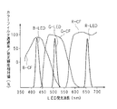
- FIG. 13 is a schematic diagram showing the relationship between the transmission characteristics of the color filter of the liquid crystal panel and the wavelengths of the LEDs of RGB.
- the characteristic of a blue (B) color filter hereinafter referred to as B-CF
- B-CF blue color filter
- the ratio of the light transmission amount of the B-LED and the light transmission amount of the G-LED with respect to the B-CF is always constant. Light leakage does not occur by incorporating the leakage amount of the G-LED with respect to the CF.
- FIG. 14 is a schematic diagram for explaining light leakage caused by a change in the light emission rate.
- a green rectangular image 101 is displayed on a blue background image 100 on the screen.
- the screen is divided into a plurality of areas including area A and area B, and the rectangular image 101 is displayed in area A and has a size slightly smaller than the size of area A.
- the backlight is divided so as to correspond to each area of the screen, and light emission is controlled for each area.
- the contour 102 along the contour of the rectangular image 101 and the periphery thereof become a bright blue color due to green light leakage (a phenomenon in which a ring of light can be seen faintly around the halo phenomenon).
- the image quality will be impaired.
- the halo phenomenon occurs at a position where the viewer does not care, such as the edge of the screen, or when the halo phenomenon disappears in a short time, the color purity of the original image is impaired by controlling the light emission of each LED. In other words, the viewer may feel uncomfortable with the display image.
- the present invention has been made in view of such circumstances, and an object of the present invention is to provide an image display device that reduces the possibility of deteriorating the quality of an original image by suppressing luminance unevenness or color unevenness more than necessary. And providing an image display method.
- the image display device separately controls a light emission rate of each of a plurality of light sources that irradiates light of a color corresponding to the color filter on a display unit including a plurality of color filters.
- detection means for detecting luminance unevenness or color unevenness generated in the display unit due to light leakage from a light source other than the light source corresponding to the color filter, and a part of the display unit
- a detection limiting unit for limiting detection by the detection unit in the control unit, and a light emission rate of the light source is controlled based on a detection result of the detection unit, and light from a plurality of the light sources is combined and incident on the color filter.
- control means for reducing the saturation of the light to bring the light close to white.
- the image display device is characterized in that the control means controls the light emission rate of the light source, and additively mixes the light from the light source to reduce the saturation so that it approaches white. To do.
- the detection restricting unit includes a type obtaining unit that obtains a type of an image displayed on the display unit, and an arbitrary one in the display unit based on the type obtained by the type obtaining unit. And setting means for setting an area, and the detection means limits the detection in the area set by the setting means.
- the detection means detects luminance unevenness or color unevenness generated in a part of the display unit
- the control means is a light source at a position corresponding to a portion detected by the detection means.
- the light emission rate is controlled.
- the image display device further includes display control means for displaying an OSD display image on the display unit, and the detection restricting means restricts detection based on the OSD display image displayed by the display control means. It is characterized by that.
- the image display device is characterized in that the detection restricting means restricts detection at a position of an OSD display image displayed on the display unit by the display control means.
- the image display apparatus further includes receiving means for receiving a signal from an external device, and the display control means displays an OSD display image based on the signal received by the receiving means. It is characterized by.
- the display unit including the color filters of a plurality of colors is independently controlled in the display unit by individually controlling the light emission rates of the plurality of light sources that emit light of the colors corresponding to the color filters.
- the image display method for displaying an image when detecting luminance unevenness or color unevenness generated in the display unit due to light leakage from a light source other than the light source corresponding to the color filter, detection in a part of the display unit Performing the detection while limiting the luminance, and controlling the light emission rate of the light source based on the detection result of luminance unevenness or color unevenness, and the light from a plurality of the light sources is combined and incident on the color filter The step of bringing the light closer to white by lowering the saturation of the light is provided.
- the light emission rate of the light source is controlled based on the detection result, and a plurality of light sources incident on the color filter are detected.
- the synthesized light is brought closer to white.
- the display unit reduces the transmittance in order to maintain the display color. As a result, it is possible to reduce the possibility that unnecessary light from the light source is transmitted and luminance unevenness or color unevenness is generated to impair the quality of an image displayed on the display unit.
- the light emission rate of the light source is not controlled in order to reduce these.
- luminance unevenness or color unevenness generated in a place where the user does not care is not reduced, and priority is given to suppressing luminance unevenness or color unevenness so as not to deteriorate the image quality. Can be. Therefore, the original image quality can be maintained.
- the light source other than the light source corresponding to the color filter means a light source other than the light source having an emission wavelength corresponding to each color filter.
- the color filter is composed of three colors of R (red), G (green), and B (blue)
- the light source corresponding to the color filter of R (red) is a red light source
- G (green) , B (blue) are green and blue light sources, respectively.
- the light sources other than the light source corresponding to the color filter are the green and blue light sources.
- the G (green) color filter means red and blue light sources
- the B (blue) color filter means red and green light sources.
- white light can be obtained by mixing light of each color using light sources of three colors of red, green, and blue.
- detection of luminance unevenness or color unevenness in an area set in the display unit is limited based on the type of image to be displayed. Since brightness unevenness or color unevenness can be ignored depending on the type of image, the light emission rate of the light source can be controlled more than necessary to reduce the possibility of degrading the image quality.
- the light emission rate of the light source at a position corresponding to a part of the display unit that detects luminance unevenness or color unevenness is controlled.
- luminance unevenness or the like does not occur in a part of the detected display unit, it is not necessary to control the light emission rate of the light source corresponding to the part, and the power consumption of the light source can be reduced.
- the detection is limited, it is not necessary to control the light emission rate of the light source corresponding to that portion, and the power consumption of the light source can be similarly reduced.
- detection of luminance unevenness or color unevenness is limited by information related to the OSD display image, for example, the display position, size, or display content of the OSD display image. Since the OSD display image is displayed at the edge of the screen and may disappear in a short time, it may not be necessary to perform control for reducing luminance unevenness or color unevenness caused by the OSD display image. For this reason, even if luminance unevenness or color unevenness occurs due to the OSD display image, by limiting detection so that the light emission rate is not controlled, the light emission rate is controlled more than necessary, and the quality of other images is improved. It can be prevented from lowering.
- the detection of luminance unevenness or color unevenness at the position where the OSD display image is displayed is limited.
- the light emission rate can be controlled more than necessary and the quality of other images can be prevented from being deteriorated.
- the luminance unevenness or the color unevenness is similarly obtained.
- the present invention limits the detection of a part of the display unit when detecting luminance unevenness or color unevenness, and makes combined light from a plurality of light sources incident on a color filter approach white based on the detection result. Control the luminous rate of the light source.
- the display unit reduces the transmittance in order to maintain the display color. As a result, it is possible to reduce the possibility that unnecessary light from the light source is transmitted and luminance unevenness or color unevenness is generated to impair the quality of an image displayed on the display unit.
- the light emission rate of the light source is not controlled in order to reduce these.
- luminance unevenness or color unevenness generated in a place where the user does not care is not reduced, and priority is given to suppressing luminance unevenness or color unevenness so as not to deteriorate the image quality. Can be. Therefore, the original image quality can be maintained.
- the liquid crystal display device is an image display device of the present invention, and displays an image based on an RGB video signal input from the outside.
- the RGB video signal may be received by a television radio wave, read from a recording medium such as a DVD (Digital Versatile Disc), or input via a network. May be.
- FIG. 1 is a block diagram showing a configuration of a liquid crystal display device according to the present embodiment.
- the liquid crystal display device 20 includes a control unit 1, a reception unit 2, a video processing unit 3, an area active processing unit 4, a display panel unit 10, and a drive unit 5 that drives the backlight 11.
- the display panel unit 10 is provided with a backlight 11 on the back side and includes a display unit on the front side for displaying an image based on RGB video signals.
- the display panel unit 10 includes a display element having a number of pixels corresponding to the screen display resolution.
- the display element has a color filter that transmits only necessary light (wavelength) and blocks other light (wavelength), and has three colors of red (R), green (G), and blue (B). Any light is transmitted.
- a color image is displayed on the display screen as light passes through the display element. Note that the amount of light transmitted through the display element is determined by the transmittance of the display element.
- the transmittance is a ratio at which the display element can pass the light irradiated by the backlight 11.
- the backlight 11 is a light source that emits light from the back side of the display panel unit 10.
- FIG. 2 is a diagram schematically illustrating the configuration of the backlight 11.
- the backlight 11 is entirely divided into a plurality of rectangular regions 110, and each region 110 is provided with an R-LED 11a, a G-LED 11b, and a B-LED 11c.
- the backlight 11 is controlled to emit light for each area 110.
- one LED 11a, 11b, and 11c is provided in the region 110, but a plurality of LEDs may be provided. For example, when a light amount is necessary, two or more LEDs of the same color may be provided.
- the receiving unit 2 receives the RGB video signal read by the playback device 12 from a recording medium such as a DVD.
- the receiving unit 2 may be one that receives television radio waves, or one that receives data transmitted via a WAN (Wide Area Network) or the like.
- the video processing unit 3 performs various signal processing on the RGB video signal received by the receiving unit 2. For example, the video processing unit 3 acquires image data (hereinafter, also referred to as a frame) extracted from the RGB video signal at regular time intervals, acquires the gradation of the image data, and adjusts the size of the image data. The various information is output to the control unit 1 and the area active processing unit 4. The video processing unit 3 also generates RGB signals, digital conversion processing, color space conversion processing, scaling processing, color correction processing, synchronization detection processing, gamma correction processing, OSD (On-Screen Display) display processing, and the like. The signal processing is appropriately executed.
- image data hereinafter, also referred to as a frame
- the various information is output to the control unit 1 and the area active processing unit 4.
- the video processing unit 3 also generates RGB signals, digital conversion processing, color space conversion processing, scaling processing, color correction processing, synchronization detection processing, gamma correction processing, OSD (On-Screen Display) display processing, and the like
- OSD display means displaying an OSD image on the display panel unit 10.
- 3 and 4 are diagrams showing an example of the OSD display.
- 3 is an OSD display when a remote controller (hereinafter referred to as a remote controller) of the liquid crystal display device 20 is operated.
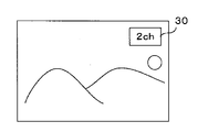
- FIG. 3A is a channel display
- FIG. 3B is a volume display
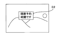
- FIG. 3C is a notification display
- 3D is a diagram illustrating an example of image quality mode display.
- the channel display the channel number 30 currently being viewed is displayed.
- a volume bar 31 is displayed when the viewer adjusts the volume with a remote controller or the like.
- a notification image 32 for notifying the state of the liquid crystal display device 20, the time for viewing reservation, the start of information download, a warning, and the like is displayed at the center of the screen.
- the mode notification image 33 is displayed when the viewer changes the image quality with a remote controller or the like.
- the image quality mode includes a dynamic mode, a standard mode, a movie mode, and the like, and the brightness or contrast of the image is set to a predetermined value for each mode.
- FIG. 4 is an OSD display when the playback device 12 which is an external device is operated
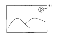
- FIG. 4A is a diagram showing an example of a playback mode display
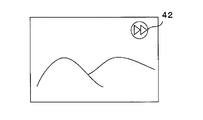
- FIG. 4B is a diagram showing an example of a fast-forward mode display.
- a playback icon 41 is displayed at the upper right of the screen.
- the fast forward icon 42 is displayed on the upper right of the screen.
- the area active processing unit 4 determines the peak value of each color component of one frame corresponding to the region 110 based on the gradation of the image data input from the video processing unit 3 and a mix rate described later input from the control unit 1.
- the optimum light emission rate of each LED 11a, 11b, 11c is determined according to the above.
- the peak value of each color component of RGB of one frame is 10% for the red (R) component, 60% for the green (G) component, and 30 for the blue (B) component, compared to the dynamic range. %.
- the light emission rates of the LEDs 11a, 11b, and 11c are also 10%, 60%, and 30%.
- the area active processing unit 4 determines the light emission rate for all the regions 110 in units of frames.
- the area active processing unit 4 determines a transmittance control value (voltage value) for controlling the transmittance of the display element of the display panel unit 10 for each frame based on the gradation of the image data and the determined light emission rate. .
- the area active processing unit 4 outputs the determined light emission rate and transmittance control value to the control unit 1 and the drive unit 5.
- the light transmission amount from the display element of the display panel unit 10 is obtained by multiplying the light emission rate of the LED corresponding to the display element by the transmittance of the display element.
- the light emission rate and the transmittance control value based on the gradation level of the image data, for example, when the gradation level of the image data in a certain area of the display panel unit 10 is small, in the area 110 corresponding to that area.
- the power consumption of the backlight 11 can be reduced.
- the drive unit 5 includes a panel drive unit 51 and a backlight drive unit 52.
- the panel drive unit 51 is a drive circuit for the display panel unit 10 and performs control to change the transmittance of the display element of the display panel unit 10 according to the transmittance control value input from the area active processing unit 4.
- the transmittance control value output from the panel drive unit 51 is charged to the electrode in each display element of the display panel unit 10. Then, the tilt amount of the liquid crystal related to the display element changes according to the charged voltage, and as a result, the transmittance of the display element is controlled.
- the backlight drive unit 52 is a drive circuit for the backlight 11, and performs control to change the light emission rate of each LED 11 a, 11 b, 11 c of the backlight 11 based on the light emission rate input from the area active processing unit 4. .
- the backlight drive unit 52 performs light emission control of the LEDs 11a, 11b, and 11c for each region 110.
- the control unit 1 is a microcomputer including a CPU (Central Processing Unit) and a ROM (Read Only Memory).
- the control unit 1 drives and controls each part of the liquid crystal display device 20 to drive and control the entire liquid crystal display device 20. To do.
- the control unit 1 generates the halo phenomenon (brightness unevenness or color unevenness) occurring in each region 110 based on the transmittance control value (voltage value) and the light emission rates of the LEDs 11a, 11b, and 11c. It is detected by the video processing unit 3.
- the control unit 1 changes the mix rate described later in order to reduce the halo phenomenon.
- the control part 1 determines the light emission rate of LED11a, 11b, 11c in the area active process part 4 based on the changed mix rate, and makes synthetic
- the halo phenomenon is a phenomenon in which light from an LED is generated by light leakage that passes through a filter of a color that is not supported, and an outline of the image and a circle of light can be seen in the surroundings.
- the controller 1 detects the occurrence of the halo phenomenon based on the balance of the light emission rates of the LEDs 11a, 11b, and 11c and the balance of the transmittance of the display elements.
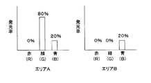
- the light emission rates of the LEDs 11a, 11b, and 11c are set to 0%, 80%, and 20%, and in the area B, 0%, 0%, and 20%. %, And the transmittance of the display element is 100%.
- the light leakage from the G-LED 11b to blue (B) is 10% of that of the G-LED 11b, and the allowable value of light leakage is less than 20% with respect to the transmission amount of blue (B).
- the allowable value of light leakage is a limit value of the amount of light leakage that may impair image quality.
- the video processing unit 3 calculates the amount of light leakage, and detects the occurrence of the halo phenomenon when the calculation result is larger than the allowable value of light leakage.
- the video processing unit 3 detects the occurrence of the halo phenomenon described above for each pixel of the display element for each frame. Next, the video processing unit 3 also performs detection for pixels adjacent in the vertical and horizontal directions of the pixel in which the occurrence of the halo phenomenon is detected, and detects the continuity of the pixels in which the occurrence of the halo phenomenon is detected.
- the image processing unit 3 detects the occurrence of the halo phenomenon in a plurality of vertical and horizontal pixels, in other words, the pixel in which the occurrence of the halo phenomenon is detected has a predetermined area (for example, an area of 50% of one frame). ), It is determined that a halo phenomenon has occurred in the frame.
- control part 1 is a process which reduces a halo phenomenon, for example, when it determines with the halo phenomenon having generate
- the control unit 1 brings light synthesis from the LEDs 11a, 11b, and 11c closer to white light by additive color mixing. Specifically, since white light has the same light emission rate of each color LED, the area active processing unit 4 makes the light emission rates of the respective LEDs 11a, 11b, and 11c the same in order to approach white light.
- the LED having the maximum light emission rate is not subjected to light emission control, and the light emission control is performed so that the light emission rates of the other LEDs are close to the maximum light emission rate.
- the area active processing unit 4 brings the light emission rates of the R-LED 11a and the B-LED 11c close to the light emission rate of the G-LED 11b.
- the light emission rate of each LED determined by the area active processing unit 4 when reducing the halo phenomenon is determined based on the mix rate.
- the mix rate is a ratio when changing the light emission rate of each LED 11a, 11b, 11c, and is determined by the control unit 1. For example, when the light emission rates of the LEDs 11a, 11b, and 11c are optimal light emission rates for the respective color components of the image data determined by the area active processing unit 4, the mix rate is zero. In other words, when the mix rate is 0, the light emission rates of the LEDs 11a, 11b, and 11c are not changed. Further, when the light emission rates of the LEDs 11a, 11b, and 11c are matched with the maximum light emission rate, that is, when the backlight 11 is a white light source, the mix rate is 1.
- the mix rate can be determined by a predetermined function.
- each light emission rate of the mix rate “0” is r1, g1, b1
- each light emission rate of the white light source is r2, g2, b2
- the mix rate is m (0 ⁇ m ⁇ 1)
- the light emission rate rm by the mix rate , Gm, and bm are as follows.
- FIG. 5 is a schematic diagram showing the light emission rates of LEDs of different colors at different mix rates
- FIG. 5A shows a mix rate of 0
- FIG. 5B shows a mix rate of 1
- FIG. 5C shows a mix rate of 0.4.
- the mix rate is 0
- the light emission rates of the LEDs 11a, 11b, and 11c are 10%, 60%, and 30% (see FIG. 5A).
- the mix rate is 1 (100%)
- the light emission rates of the LEDs 11a, 11b, and 11c are all 60% (see FIG. 5B).
- the mix rate is 0.4 (40%)
- the light emission rates of the LEDs 11a, 11b, and 11c are 30%, 60%, and 42% (see FIG. 5C).
- the control unit 1 determines the optimum mix rate according to the detection result of the video processing unit 3, so that the light leakage amount of the LED of one color becomes less than the allowable value of the light leakage amount of the LED of the other color, The halo phenomenon can be reduced.
- the mix rate is determined to be 33%.
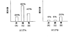
- FIG. 6 is a schematic diagram showing a light emission rate when the light emission rates of the LEDs 11a, 11b, and 11c are changed at a mix rate of 33%
- FIG. 6A shows a case before the change
- FIG. 6B shows a case after the change.
- the light emission rates of the LEDs 11a, 11b, and 11c are 26%, 80%, and 40%, and in the case of area B, they are 6%, 6%, and 20%.
- the amount of light leakage of the G-LED 11b having an emission rate of 80% is 8%.
- the light leakage amount of the B-LED 11c having a light emission rate of 40% is 4%, and its allowable value is doubled to 8%. Since the light leakage amount of the G-LED 11b is 8%, the light leakage amount of the B-LED 11c is less than the allowable value. As a result, the halo phenomenon occurring in the contour portion 102 and its periphery is reduced.
- control unit 1 may control only the LEDs 11a, 11b, and 11c included in the region 110 where the halo phenomenon occurs based on the mix ratio, or the LEDs 11a, 11b, and 11b in all the regions 110. You may make it carry out light emission control of 11c.
- the LEDs 11a, 11b, and 11c in the region 110 where the halo phenomenon occurs are controlled to emit light
- the LEDs 11a, 11b, and 11c in the region 110 where the halo phenomenon does not occur are controlled so as to correspond to the region 110. It can prevent that the color purity of a display screen falls.
- the power consumption of the backlight 11 can be reduced by keeping the light emission rate low.
- the color purity of the entire screen can be made uniform and the processing can be simplified, so that the circuit scale can be reduced. Can do.
- the control unit 1 may make the light emission of the LEDs 11a, 11b, and 11c continuously approach white light, or may make it gradually approach.
- the color purity can be changed smoothly by continuously changing the color purity, and the color purity can be changed without a sense of incongruity by changing it step by step at a timing that the viewer does not notice.
- the viewer may not care about the halo phenomenon depending on the position or size of the halo phenomenon. In this case, by slowly approaching white, it is possible to prevent the viewer from noticing that the color of the image displayed on the display panel unit 10 has changed. Further, when the halo phenomenon is eliminated by bringing the color closer to white earlier, an image that does not impair the quality of the image can be displayed.
- the control unit 1 sets an area for detecting the occurrence of the above-described halo phenomenon (hereinafter referred to as a detection area) and an area for not performing detection (hereinafter referred to as a non-detection area) based on the OSD image.
- the OSD image may be displayed at the end of the screen for a short time, such as channel number 30 in FIG. 3A.
- the halo phenomenon that occurs due to the OSD image also disappears in a short time, and the viewer may not be concerned about the occurrence of the halo phenomenon.
- the control unit 1 sets the OSD image and its periphery as a non-detection region and the others as detection regions.
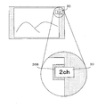
- the control unit 1 sets the detection area and the non-detection area according to the area 110 of the backlight 11.
- the screen of the display panel unit 10 is divided into a plurality of areas like the area 110, and a detection area and a non-detection area are set for each of the divided areas. Since the backlight 11 is controlled to emit light for each region 110, when the region 110 corresponds to a non-detection region, it is not necessary to perform light emission control of the LEDs included in the region 110, and the power consumption of the backlight 11 is reduced. Can be made.
- FIGS. 7 and 8 are schematic diagrams for explaining a detection region set when an OSD image is displayed.
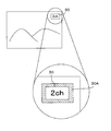
- the channel number 30 is displayed at the upper right of the screen.
- the control unit 1 sets the channel number 30 and the surrounding area 30A as non-detection areas and sets the others as detection areas. In this case, even if the halo phenomenon occurs because the channel number 30 is displayed, the process for reducing the halo phenomenon is not performed.
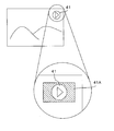
- the reproduction icon 41 is displayed on the upper right of the screen.
- the control unit 1 sets the playback icon 41 and the surrounding area 41A as non-detection areas and sets the others as detection areas.
- the area 41 ⁇ / b> A is rectangular, but may be circular like the playback icon 41.
- the control unit 1 sets the OSD image and its periphery as a non-detection area and sets the others as detection areas.
- FIG. 9 is a schematic diagram for explaining a detection area when an OSD image is displayed when no image is displayed on the entire screen.
- the case where the image is not displayed on the entire screen is a case where, for example, a belt-like black image is displayed at both ends of the screen when the aspect ratio of the image is changed.
- the control unit 1 removes the channel number 30 that does not overlap the black image and the surrounding area 30B.
- the detection area is set, and the other is set as the detection area. Since the halo phenomenon does not occur in the black image portion, the black image portion becomes a non-detection region.
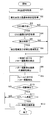
- FIG. 10 is a flowchart showing processing executed in the liquid crystal display device 20.
- the video processing unit 3 acquires the RGB video signal from the playback device 12 via the receiving unit 2 (S1), and acquires the light emission rate and transmittance control value in one frame of the RGB video signal (S2).
- the light emission rate and transmittance control values are determined by the area active processing unit 4 or estimated by the video processing unit 3.
- the control unit 1 determines whether or not to perform OSD display (S3).
- OSD display is not performed (S3: NO)
- the process proceeds to S7.
- OSD display S3: YES
- the control unit 1 acquires the contents of the OSD image to be displayed (S4).
- the control unit 1 determines whether or not to limit the detection of the occurrence of the halo phenomenon based on the contents of the OSD image (S5).
- the control unit 1 sets a detection area and a non-detection area (S6). Specifically, as described with reference to FIGS. 8 to 10, the control unit 1 sets the OSD image and its periphery as a non-detection area, and sets other parts as detection areas. Thus, even if the halo phenomenon occurs in the OSD image and its surroundings, the video processing unit 3 does not perform light emission control in that region, and the quality of the original image does not deteriorate. Thereafter, the process proceeds to S7.
- control unit 1 proceeds to S7 without setting the detection area and the non-detection area. At this time, the control unit 1 sets the entire screen as a detection area.
- control unit 1 detects the occurrence of the halo phenomenon in one pixel of the display element (S7), and detects the continuity of the pixels in which the occurrence of the halo phenomenon is detected (S8). From the result, the control unit 1 detects the occurrence of the halo phenomenon in the frame (S9). Specifically, as described above, the control unit 1 calculates the light leakage amount of the LED, and detects the occurrence of the halo phenomenon based on the calculation result.
- the control unit 1 determines whether or not the occurrence of the halo phenomenon in the frame is detected from the detection result of S9 (S10). When the occurrence of the halo phenomenon is not detected (S10: NO), this process ends. In other words, the control unit 1 ends the process in this frame and executes the same process for the next frame. When the occurrence of the halo phenomenon is detected (S10: YES), the control unit 1 determines whether four or more frames in which the occurrence of the halo phenomenon is detected are continued (S11). If not continuous (S11: NO), this process ends. That is, the control unit 1 ends the process in this frame and executes the same process for the next frame.
- the control unit 1 executes processing for reducing the halo phenomenon (S12). Specifically, the control unit 1 determines the optimum mix ratio, and reduces the halo phenomenon by setting the light leakage amount of one color LED to be equal to or less than the allowable value of the light leakage amount of another color LED. To do. At this time, the control unit 1 may control only the LEDs 11a, 11b, and 11c included in the region 110 where the halo phenomenon occurs, or may control the LEDs 11a, 11b, and 11c in all the regions 110. It may be. Thereafter, this process ends.
- control part 1 finishes the control which changes the mix rate of LED, when the halo phenomenon is no longer detected when performing the control which changes the mix rate of LED11a, 11b, 11c. That is, the control unit 1 performs control to keep the light emission of the LEDs 11a, 11b, and 11c approaching white light away from the white light.
- the liquid crystal display device 20 does not detect the occurrence of the halo phenomenon in the region by setting the OSD image and the periphery thereof to the non-detection region. As a result, even when the halo phenomenon occurs due to the OSD display, the process of reducing the halo phenomenon is not performed, and the quality of the original image is not deteriorated. Thus, by giving priority to the reduction process of the halo phenomenon in which the display disappears in a short time, it is possible to suppress the possibility of degrading the original image quality.
- the liquid crystal display device detects the occurrence of the halo phenomenon in units of frames of the RGB video signal, and emits light from the LEDs 11a, 11b, and 11c when white light is emitted. Move closer to Thereby, the amount of light leakage from the backlight 11 can be reduced. As a result, it is possible to reduce the possibility that unnecessary light from the backlight 11 is transmitted and the quality of the image displayed on the display panel unit 10 is impaired.
- the halo phenomenon when it is determined that the halo phenomenon may occur for four consecutive frames, the halo phenomenon is reduced.
- the number of consecutive frames can be changed as appropriate.
- the continuous number may be determined according to the time interval at which the frames are extracted.
- the LEDs 11a, 11b, and 11c may be controlled only for the region 110 where the halo phenomenon occurs, or the LEDs 11a, 11b, and 11c in all the regions 110 may be controlled. Good.
- a non-detection area is not set, and a first detection area that detects the occurrence of a halo phenomenon based on the content of an image to be displayed, and a second detection that has a lower detection level of the occurrence of a halo phenomenon than the first detection area Set the area.
- the detection level is determined by the allowable value of light leakage when detecting the occurrence of the halo phenomenon described above. Since the occurrence of the halo phenomenon is detected when the amount of light leakage is greater than the allowable value, the allowable value increases and the occurrence of the halo phenomenon is difficult to detect. Therefore, since the detection level decreases as the allowable value increases, the second detection region 43 is set to have a higher allowable value than the first detection region 40.
- the control unit 1 of the liquid crystal display device 20 acquires genre information. Images displayed on the display panel unit 10 based on the RGB video signals are classified into a plurality of genres such as drama, movie, and news report. The genre information is received by the receiving unit 2 from the playback device 12 together with the RGB signals. In addition, when the receiving unit 2 receives a television broadcast, the control unit 1 may acquire genre information by EPG (Electric Program) or acquire genre information set by a viewer. You may do it.
- EPG Electronic Program
- the control unit 1 sets the first and second detection areas based on the acquired genre information.
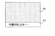
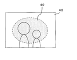
- FIG. 11 is a diagram schematically showing first and second detection areas set based on genre information.
- FIG. 11A is a diagram showing the first and second detection areas set in the case of, for example, a foreign movie, a news program, a variety program, or the like in which subtitles are frequently used.
- the second detection area 43 is set in the lower part of the screen where there is a high possibility that subtitles are displayed.
- the first detection area 40 is set in a portion other than the portion set in the second detection area 43.
- FIG. 11B is a diagram showing the first and second detection areas set in the case of a drama, for example.
- the first detection area 40 is set at the center of the screen.
- the second detection region 43 is set in the peripheral portion of the first detection region 40.
- the detection level of the occurrence of the halo phenomenon is increased in the portion of interest of the viewer, and the detection level of the other portion is decreased, thereby performing the process of reducing the occurrence of the halo phenomenon more than necessary, and the backlight 11. It is possible to suppress an increase in power consumption.
- FIG. 12 is a flowchart showing processing executed in the liquid crystal display device 20.
- the video processing unit 3 acquires the RGB video signal from the playback device 12 via the receiving unit 2 (S20), and acquires the light emission rate and transmittance control value in one frame of the RGB video signal (S21).
- the light emission rate and transmittance control values are determined by the area active processing unit 4 or estimated by the video processing unit 3.
- the control unit 1 acquires genre information (S22).
- the genre information may be acquired from the EPG or set by the viewer.
- the control unit 1 determines whether or not to limit the detection of occurrence of the halo phenomenon (S23).
- the control unit 1 sets the first detection region and the second detection region (S24). Specifically, as described with reference to FIG. 11, the control unit 1 sets the lower part of the screen or the edge of the screen where the possibility of displaying subtitles is set as the second detection area 43, and sets the other parts as the first detection area. Set to 40. Thereafter, the process proceeds to S25.
- the control unit 1 shifts the process to S25 without setting the first detection region and the second detection region. At this time, the control unit 1 sets the same detection level for the entire screen.
- the process after S25 is the same as that after S7 of FIG. 10, description is abbreviate
- the detection level is lowered based on the content of the image to be displayed at a position where the viewer does not care even if the halo phenomenon occurs.
- the process of reducing the halo phenomenon that the viewer does not care about is not performed, and the quality of the original image does not deteriorate. For this reason, priority can be given to the halo phenomenon reduction process that does not bother the user, thereby suppressing the possibility of degrading the original image quality.
Landscapes
- Engineering & Computer Science (AREA)
- Physics & Mathematics (AREA)
- Computer Hardware Design (AREA)
- General Physics & Mathematics (AREA)
- Theoretical Computer Science (AREA)
- Multimedia (AREA)
- Signal Processing (AREA)
- Control Of Indicators Other Than Cathode Ray Tubes (AREA)
- Liquid Crystal Display Device Control (AREA)
- Liquid Crystal (AREA)
- Transforming Electric Information Into Light Information (AREA)
- Controls And Circuits For Display Device (AREA)
Abstract
Description
rm=(r2-r1)×m+r1
gm=(g2-g1)×m+g1
bm=(b2-b1)×m+b1
2 受信部
3 映像処理部
4 エリアアクティブ処理部
5 駆動部
20 液晶表示装置
Claims (8)
- 複数色のカラーフィルタを含む表示部に、前記カラーフィルタに対応する色の光を照射する複数の光源それぞれの発光率を各別に制御して、前記表示部に画像を表示する画像表示装置において、
前記カラーフィルタに対応する光源以外の光源からの光漏れに起因して前記表示部に生ずる輝度ムラ又は色ムラを検出する検出手段と、
前記表示部の一部における前記検出手段による検出を制限する検出制限手段と、
前記検出手段の検出結果に基づいて前記光源の発光率を制御し、複数の前記光源からの光が合成して前記カラーフィルタに入射される光の彩度を下げることによって前記光を白色に近づける制御手段と
を備えることを特徴とする画像表示装置。 - 前記制御手段は、
前記光源の発光率を制御し、前記光源からの光を加法混色して彩度を下げることによって白色に近づけるようにしてある
ことを特徴とする請求項1に記載の画像表示装置。 - 前記検出制限手段は、
前記表示部に表示される画像の種類を取得する種類取得手段と、
該種類取得手段が取得した種類に基づいて前記表示部に任意の領域を設定する設定手段と
を有し、
該設定手段が設定した領域における前記検出手段による検出を制限するようにしてある
ことを特徴とする請求項1又は2に記載の画像表示装置。 - 前記検出手段は、
前記表示部の一部に生じる輝度ムラ又は色ムラを検出し、
前記制御手段は、
前記検出手段が検出した部分に対応する位置にある光源の発光率を制御するようにしてある
ことを特徴とする請求項1から3の何れか一つに記載の画像表示装置。 - 前記表示部にOSD表示画像を表示する表示制御手段
をさらに備え、
前記検出制限手段は、
前記表示制御手段が表示するOSD表示画像に基づいて検出を制限するようにしてある
ことを特徴とする請求項1から4の何れか一つに記載の画像表示装置。 - 前記検出制限手段は、
前記表示制御手段が表示部に表示するOSD表示画像の位置における検出を制限するようにしてある
ことを特徴とする請求項5に記載の画像表示装置。 - 外部機器から信号を受信する受信手段
をさらに備え、
前記表示制御手段は、
前記受信手段が受信した信号に基づいて、OSD表示画像を表示するようにしてある
ことを特徴とする請求項5又は6に記載の画像表示装置。 - 複数色のカラーフィルタを含む表示部に、前記カラーフィルタに対応する色の光を照射する複数の光源それぞれの発光率を独立に制御して、前記表示部に画像を表示する画像表示方法において、
前記カラーフィルタに対応する光源以外の光源からの光漏れに起因して前記表示部に生ずる輝度ムラ又は色ムラを検出する際、前記表示部の一部における検出を制限して前記検出を行うステップ、及び、
輝度ムラ又は色ムラの検出結果に基づいて前記光源の発光率を制御し、複数の前記光源からの光が合成して前記カラーフィルタに入射される光の彩度を下げることによって前記光を白色に近づけるステップ
を備えることを特徴とする画像表示方法。
Priority Applications (6)
| Application Number | Priority Date | Filing Date | Title |
|---|---|---|---|
| EP10731310A EP2388767A4 (en) | 2009-01-19 | 2010-01-16 | IMAGE DISPLAY DEVICE AND IMAGE DISPLAY PROCESS |
| CN201080005363.4A CN102282605B (zh) | 2009-01-19 | 2010-01-16 | 图像显示装置及图像显示方法 |
| MX2011007508A MX2011007508A (es) | 2009-01-19 | 2010-01-16 | Dispositivo de visualizacion de imagen y metodo de visualizacion de imagen. |
| US13/145,079 US8842109B2 (en) | 2009-01-19 | 2010-01-16 | Image display device and image display method |
| RU2011134648/08A RU2479049C1 (ru) | 2009-01-19 | 2010-01-16 | Устройство отображения изображений и способ отображения изображений |
| BRPI1007265A BRPI1007265A2 (pt) | 2009-01-19 | 2010-01-16 | dispositivo de exibição de imagem e método de exibição de imagem. |
Applications Claiming Priority (2)
| Application Number | Priority Date | Filing Date | Title |
|---|---|---|---|
| JP2009009006A JP4528861B2 (ja) | 2009-01-19 | 2009-01-19 | 画像表示装置及び画像表示方法 |
| JP2009-009006 | 2009-01-19 |
Publications (1)
| Publication Number | Publication Date |
|---|---|
| WO2010082641A1 true WO2010082641A1 (ja) | 2010-07-22 |
Family
ID=42339894
Family Applications (1)
| Application Number | Title | Priority Date | Filing Date |
|---|---|---|---|
| PCT/JP2010/050445 Ceased WO2010082641A1 (ja) | 2009-01-19 | 2010-01-16 | 画像表示装置及び画像表示方法 |
Country Status (8)
| Country | Link |
|---|---|
| US (1) | US8842109B2 (ja) |
| EP (1) | EP2388767A4 (ja) |
| JP (1) | JP4528861B2 (ja) |
| CN (1) | CN102282605B (ja) |
| BR (1) | BRPI1007265A2 (ja) |
| MX (1) | MX2011007508A (ja) |
| RU (1) | RU2479049C1 (ja) |
| WO (1) | WO2010082641A1 (ja) |
Families Citing this family (10)
| Publication number | Priority date | Publication date | Assignee | Title |
|---|---|---|---|---|
| US8922474B2 (en) * | 2010-02-10 | 2014-12-30 | Sharp Laboratories Of America, Inc. | Method of performing off axis halo reduction by generating an off-axis image and detecting halo artifacts therein |
| KR101329969B1 (ko) * | 2010-07-09 | 2013-11-13 | 엘지디스플레이 주식회사 | 액정 표시 장치와 그의 로컬 디밍 구동 방법 |
| US8605124B2 (en) | 2011-08-30 | 2013-12-10 | Sharp Laboratories Of America, Inc. | Multi-primary display with area active backlight |
| US9082349B2 (en) | 2011-08-30 | 2015-07-14 | Sharp Laboratories Of America, Inc. | Multi-primary display with active backlight |
| CN103971624A (zh) * | 2013-01-28 | 2014-08-06 | 富泰华工业(深圳)有限公司 | 漏光检测系统及方法 |
| CN107111995B (zh) * | 2014-10-03 | 2019-08-23 | 夏普株式会社 | 影像处理装置、显示装置、配置判定装置、配置判定方法、记录介质 |
| CN105635789B (zh) * | 2015-12-29 | 2018-09-25 | 深圳Tcl数字技术有限公司 | 降低视频图像中osd亮度的方法和装置 |
| US20190057673A1 (en) * | 2016-01-18 | 2019-02-21 | Waveshift Llc | Method and apparatus for reducing myopiagenic effect of electronic displays |
| CN112614459A (zh) * | 2020-10-30 | 2021-04-06 | 西安诺瓦星云科技股份有限公司 | 基于led显示屏的osd显示方法及其装置和显示控制卡 |
| CN117405363B (zh) * | 2023-12-14 | 2024-03-01 | 东南大学 | Mini-LED分区背光显示器的光晕表征方法及系统 |
Citations (7)
| Publication number | Priority date | Publication date | Assignee | Title |
|---|---|---|---|---|
| JP2004085961A (ja) * | 2002-08-28 | 2004-03-18 | Seiko Epson Corp | 表示装置 |
| JP2005258404A (ja) * | 2004-02-09 | 2005-09-22 | Hitachi Ltd | 液晶表示装置 |
| JP2007140483A (ja) * | 2005-10-18 | 2007-06-07 | Sharp Corp | 液晶表示装置 |
| JP2007322944A (ja) * | 2006-06-03 | 2007-12-13 | Sony Corp | 表示制御装置、表示装置及び表示制御方法 |
| JP2008051905A (ja) * | 2006-08-22 | 2008-03-06 | Sharp Corp | 液晶表示装置、及びそのバックライト駆動方法 |
| JP2008102379A (ja) * | 2006-10-20 | 2008-05-01 | Hitachi Ltd | 画像表示装置及び画像表示方法 |
| WO2008096468A1 (ja) * | 2007-02-07 | 2008-08-14 | Sharp Kabushiki Kaisha | 表示装置 |
Family Cites Families (12)
| Publication number | Priority date | Publication date | Assignee | Title |
|---|---|---|---|---|
| JP4355977B2 (ja) | 1999-11-12 | 2009-11-04 | ソニー株式会社 | 映像表示装置および映像表示装置における照明制御方法 |
| ES2283376T3 (es) | 2001-01-16 | 2007-11-01 | Koninklijke Philips Electronics N.V. | Reduccion de los efectos de tipo halo en una interpolacion compensada en movimiento. |
| KR100904757B1 (ko) * | 2002-12-30 | 2009-06-29 | 엘지디스플레이 주식회사 | 액정표시장치 및 그의 제조방법 |
| KR101096720B1 (ko) * | 2004-05-28 | 2011-12-22 | 엘지디스플레이 주식회사 | 액정표시장치의 구동장치 및 방법 |
| JP5134768B2 (ja) | 2005-05-19 | 2013-01-30 | 株式会社ジャパンディスプレイイースト | 画像表示装置 |
| RU2298226C1 (ru) | 2005-10-28 | 2007-04-27 | Самсунг Электроникс Ко., Лтд. | Способ улучшения цифровых изображений |
| JP2008159550A (ja) | 2006-12-26 | 2008-07-10 | Toshiba Corp | バックライト制御装置及びバックライト制御方法 |
| US20100002027A1 (en) | 2007-02-13 | 2010-01-07 | Koninklijke Philips Electronics N.V. | Display device and method |
| JP2010530986A (ja) | 2007-06-13 | 2010-09-16 | トムソン ライセンシング | 二つの調節ステージを備えた画像表示装置 |
| BRPI0918758A2 (pt) | 2008-09-18 | 2015-12-29 | Sharp Kk | aparelho de exibição de imagem e método de exibição de imagem |
| US9378685B2 (en) * | 2009-03-13 | 2016-06-28 | Dolby Laboratories Licensing Corporation | Artifact mitigation method and apparatus for images generated using three dimensional color synthesis |
| KR100964466B1 (ko) * | 2009-11-24 | 2010-06-16 | 엘지전자 주식회사 | 디스플레이 장치 |
-
2009
- 2009-01-19 JP JP2009009006A patent/JP4528861B2/ja not_active Expired - Fee Related
-
2010
- 2010-01-16 US US13/145,079 patent/US8842109B2/en not_active Expired - Fee Related
- 2010-01-16 MX MX2011007508A patent/MX2011007508A/es unknown
- 2010-01-16 WO PCT/JP2010/050445 patent/WO2010082641A1/ja not_active Ceased
- 2010-01-16 BR BRPI1007265A patent/BRPI1007265A2/pt not_active IP Right Cessation
- 2010-01-16 RU RU2011134648/08A patent/RU2479049C1/ru not_active IP Right Cessation
- 2010-01-16 CN CN201080005363.4A patent/CN102282605B/zh not_active Expired - Fee Related
- 2010-01-16 EP EP10731310A patent/EP2388767A4/en not_active Withdrawn
Patent Citations (7)
| Publication number | Priority date | Publication date | Assignee | Title |
|---|---|---|---|---|
| JP2004085961A (ja) * | 2002-08-28 | 2004-03-18 | Seiko Epson Corp | 表示装置 |
| JP2005258404A (ja) * | 2004-02-09 | 2005-09-22 | Hitachi Ltd | 液晶表示装置 |
| JP2007140483A (ja) * | 2005-10-18 | 2007-06-07 | Sharp Corp | 液晶表示装置 |
| JP2007322944A (ja) * | 2006-06-03 | 2007-12-13 | Sony Corp | 表示制御装置、表示装置及び表示制御方法 |
| JP2008051905A (ja) * | 2006-08-22 | 2008-03-06 | Sharp Corp | 液晶表示装置、及びそのバックライト駆動方法 |
| JP2008102379A (ja) * | 2006-10-20 | 2008-05-01 | Hitachi Ltd | 画像表示装置及び画像表示方法 |
| WO2008096468A1 (ja) * | 2007-02-07 | 2008-08-14 | Sharp Kabushiki Kaisha | 表示装置 |
Also Published As
| Publication number | Publication date |
|---|---|
| JP4528861B2 (ja) | 2010-08-25 |
| RU2479049C1 (ru) | 2013-04-10 |
| CN102282605A (zh) | 2011-12-14 |
| US20110285681A1 (en) | 2011-11-24 |
| RU2011134648A (ru) | 2013-02-27 |
| CN102282605B (zh) | 2014-04-30 |
| EP2388767A4 (en) | 2012-09-26 |
| JP2010164900A (ja) | 2010-07-29 |
| MX2011007508A (es) | 2011-08-12 |
| EP2388767A1 (en) | 2011-11-23 |
| BRPI1007265A2 (pt) | 2016-02-10 |
| US8842109B2 (en) | 2014-09-23 |
Similar Documents
| Publication | Publication Date | Title |
|---|---|---|
| JP4528861B2 (ja) | 画像表示装置及び画像表示方法 | |
| JP4011104B2 (ja) | 液晶表示装置 | |
| US11942049B2 (en) | Signal processing apparatus, signal processing method, and display apparatus | |
| US9230487B2 (en) | Display device and television receiver | |
| US20110063529A1 (en) | Display apparatus driving method, display apparatus driving device, program therefor, recording medium storing program, and display apparatus | |
| CN101742069A (zh) | 电视装置 | |
| US8723848B2 (en) | Image display apparatus and image display method | |
| KR100802224B1 (ko) | 표시장치 및 그 제어방법 | |
| US9047825B2 (en) | Display device and display method | |
| US20050237293A1 (en) | Liquid crystal display apparatus | |
| JP4487005B2 (ja) | 画像表示装置及び画像表示方法 | |
| JP2013130744A (ja) | 映像表示装置 | |
| JP5153559B2 (ja) | 画像表示装置及び画像表示方法 | |
| JPWO2012164692A1 (ja) | 表示装置、及び表示制御方法 | |
| JP4487006B2 (ja) | 画像表示装置及び画像表示方法 | |
| JP4487004B2 (ja) | 画像表示装置及び画像表示方法 | |
| JP2013134335A (ja) | 液晶表示装置及び液晶テレビ | |
| HK1163910A (en) | Image display apparatus and image display method | |
| JP2010044194A (ja) | 画像表示装置およびバックライト制御回路 | |
| HK1159298A (en) | Image display device and image display method |
Legal Events
| Date | Code | Title | Description |
|---|---|---|---|
| WWE | Wipo information: entry into national phase |
Ref document number: 201080005363.4 Country of ref document: CN |
|
| 121 | Ep: the epo has been informed by wipo that ep was designated in this application |
Ref document number: 10731310 Country of ref document: EP Kind code of ref document: A1 |
|
| WWE | Wipo information: entry into national phase |
Ref document number: MX/A/2011/007508 Country of ref document: MX |
|
| WWE | Wipo information: entry into national phase |
Ref document number: 13145079 Country of ref document: US |
|
| NENP | Non-entry into the national phase |
Ref country code: DE |
|
| WWE | Wipo information: entry into national phase |
Ref document number: 2010731310 Country of ref document: EP |
|
| WWE | Wipo information: entry into national phase |
Ref document number: 5858/CHENP/2011 Country of ref document: IN |
|
| WWE | Wipo information: entry into national phase |
Ref document number: 2011134648 Country of ref document: RU |
|
| REG | Reference to national code |
Ref country code: BR Ref legal event code: B01A Ref document number: PI1007265 Country of ref document: BR |
|
| ENP | Entry into the national phase |
Ref document number: PI1007265 Country of ref document: BR Kind code of ref document: A2 Effective date: 20110719 |