WO2010084545A1 - 自動収尿装置 - Google Patents
自動収尿装置 Download PDFInfo
- Publication number
- WO2010084545A1 WO2010084545A1 PCT/JP2009/006635 JP2009006635W WO2010084545A1 WO 2010084545 A1 WO2010084545 A1 WO 2010084545A1 JP 2009006635 W JP2009006635 W JP 2009006635W WO 2010084545 A1 WO2010084545 A1 WO 2010084545A1
- Authority
- WO
- WIPO (PCT)
- Prior art keywords
- urine
- main tank
- tank
- sensor
- flow path
- Prior art date
- Legal status (The legal status is an assumption and is not a legal conclusion. Google has not performed a legal analysis and makes no representation as to the accuracy of the status listed.)
- Ceased
Links
Images



Classifications
-
- A—HUMAN NECESSITIES
- A61—MEDICAL OR VETERINARY SCIENCE; HYGIENE
- A61F—FILTERS IMPLANTABLE INTO BLOOD VESSELS; PROSTHESES; DEVICES PROVIDING PATENCY TO, OR PREVENTING COLLAPSING OF, TUBULAR STRUCTURES OF THE BODY, e.g. STENTS; ORTHOPAEDIC, NURSING OR CONTRACEPTIVE DEVICES; FOMENTATION; TREATMENT OR PROTECTION OF EYES OR EARS; BANDAGES, DRESSINGS OR ABSORBENT PADS; FIRST-AID KITS
- A61F5/00—Orthopaedic methods or devices for non-surgical treatment of bones or joints; Nursing devices ; Anti-rape devices
- A61F5/44—Devices worn by the patient for reception of urine, faeces, catamenial or other discharge; Colostomy devices
- A61F5/451—Genital or anal receptacles
-
- A—HUMAN NECESSITIES
- A61—MEDICAL OR VETERINARY SCIENCE; HYGIENE
- A61G—TRANSPORT, PERSONAL CONVEYANCES, OR ACCOMMODATION SPECIALLY ADAPTED FOR PATIENTS OR DISABLED PERSONS; OPERATING TABLES OR CHAIRS; CHAIRS FOR DENTISTRY; FUNERAL DEVICES
- A61G9/00—Bed-pans, urinals or other sanitary devices for bed-ridden persons; Cleaning devices therefor, e.g. combined with toilet-urinals
-
- A—HUMAN NECESSITIES
- A61—MEDICAL OR VETERINARY SCIENCE; HYGIENE
- A61F—FILTERS IMPLANTABLE INTO BLOOD VESSELS; PROSTHESES; DEVICES PROVIDING PATENCY TO, OR PREVENTING COLLAPSING OF, TUBULAR STRUCTURES OF THE BODY, e.g. STENTS; ORTHOPAEDIC, NURSING OR CONTRACEPTIVE DEVICES; FOMENTATION; TREATMENT OR PROTECTION OF EYES OR EARS; BANDAGES, DRESSINGS OR ABSORBENT PADS; FIRST-AID KITS
- A61F5/00—Orthopaedic methods or devices for non-surgical treatment of bones or joints; Nursing devices ; Anti-rape devices
- A61F5/44—Devices worn by the patient for reception of urine, faeces, catamenial or other discharge; Colostomy devices
-
- A—HUMAN NECESSITIES
- A61—MEDICAL OR VETERINARY SCIENCE; HYGIENE
- A61F—FILTERS IMPLANTABLE INTO BLOOD VESSELS; PROSTHESES; DEVICES PROVIDING PATENCY TO, OR PREVENTING COLLAPSING OF, TUBULAR STRUCTURES OF THE BODY, e.g. STENTS; ORTHOPAEDIC, NURSING OR CONTRACEPTIVE DEVICES; FOMENTATION; TREATMENT OR PROTECTION OF EYES OR EARS; BANDAGES, DRESSINGS OR ABSORBENT PADS; FIRST-AID KITS
- A61F5/00—Orthopaedic methods or devices for non-surgical treatment of bones or joints; Nursing devices ; Anti-rape devices
- A61F5/44—Devices worn by the patient for reception of urine, faeces, catamenial or other discharge; Colostomy devices
- A61F5/441—Devices worn by the patient for reception of urine, faeces, catamenial or other discharge; Colostomy devices having venting or deodorant means, e.g. filters ; having antiseptic means, e.g. bacterial barriers
-
- A—HUMAN NECESSITIES
- A61—MEDICAL OR VETERINARY SCIENCE; HYGIENE
- A61M—DEVICES FOR INTRODUCING MEDIA INTO, OR ONTO, THE BODY; DEVICES FOR TRANSDUCING BODY MEDIA OR FOR TAKING MEDIA FROM THE BODY; DEVICES FOR PRODUCING OR ENDING SLEEP OR STUPOR
- A61M1/00—Suction or pumping devices for medical purposes; Devices for carrying-off, for treatment of, or for carrying-over, body-liquids; Drainage systems
- A61M1/71—Suction drainage systems
- A61M1/73—Suction drainage systems comprising sensors or indicators for physical values
- A61M1/734—Visual indicating means for flow
-
- A—HUMAN NECESSITIES
- A61—MEDICAL OR VETERINARY SCIENCE; HYGIENE
- A61M—DEVICES FOR INTRODUCING MEDIA INTO, OR ONTO, THE BODY; DEVICES FOR TRANSDUCING BODY MEDIA OR FOR TAKING MEDIA FROM THE BODY; DEVICES FOR PRODUCING OR ENDING SLEEP OR STUPOR
- A61M1/00—Suction or pumping devices for medical purposes; Devices for carrying-off, for treatment of, or for carrying-over, body-liquids; Drainage systems
- A61M1/71—Suction drainage systems
- A61M1/74—Suction control
-
- G—PHYSICS
- G08—SIGNALLING
- G08B—SIGNALLING SYSTEMS, e.g. PERSONAL CALLING SYSTEMS; ORDER TELEGRAPHS; ALARM SYSTEMS
- G08B3/00—Audible signalling systems, e.g. audible personal calling systems
-
- A—HUMAN NECESSITIES
- A61—MEDICAL OR VETERINARY SCIENCE; HYGIENE
- A61M—DEVICES FOR INTRODUCING MEDIA INTO, OR ONTO, THE BODY; DEVICES FOR TRANSDUCING BODY MEDIA OR FOR TAKING MEDIA FROM THE BODY; DEVICES FOR PRODUCING OR ENDING SLEEP OR STUPOR
- A61M1/00—Suction or pumping devices for medical purposes; Devices for carrying-off, for treatment of, or for carrying-over, body-liquids; Drainage systems
- A61M1/60—Containers for suction drainage, adapted to be used with an external suction source
-
- A—HUMAN NECESSITIES
- A61—MEDICAL OR VETERINARY SCIENCE; HYGIENE
- A61M—DEVICES FOR INTRODUCING MEDIA INTO, OR ONTO, THE BODY; DEVICES FOR TRANSDUCING BODY MEDIA OR FOR TAKING MEDIA FROM THE BODY; DEVICES FOR PRODUCING OR ENDING SLEEP OR STUPOR
- A61M2209/00—Ancillary equipment
- A61M2209/08—Supports for equipment
- A61M2209/088—Supports for equipment on the body
-
- Y—GENERAL TAGGING OF NEW TECHNOLOGICAL DEVELOPMENTS; GENERAL TAGGING OF CROSS-SECTIONAL TECHNOLOGIES SPANNING OVER SEVERAL SECTIONS OF THE IPC; TECHNICAL SUBJECTS COVERED BY FORMER USPC CROSS-REFERENCE ART COLLECTIONS [XRACs] AND DIGESTS
- Y10—TECHNICAL SUBJECTS COVERED BY FORMER USPC
- Y10T—TECHNICAL SUBJECTS COVERED BY FORMER US CLASSIFICATION
- Y10T137/00—Fluid handling
- Y10T137/7287—Liquid level responsive or maintaining systems
Definitions
- the present invention relates to an automatic urine collecting device, and particularly suitable for an automatic urine collecting device for automatically collecting urine excreted by a bedridden patient or an elderly person.
- an automatic urine collection system for automatically collecting urine excreted by a bedridden patient or an elderly person.
- This automatic urine collection system generally includes a urine receiver attached to a local area of a patient or the like via a diaper, a tube connected at one end to the urine receiver, and an automatic collection connected at the other end of the tube. Mainly composed of urine device.
- this automatic urine collecting device conventionally, a collection container for storing urine discharged from a urine receiver through a tube, and a urine collected in the urine receiver are sucked and conveyed to the collection container And a suction pump are known.
- Patent Document 1 As a conventional device of this type, for example, there is a urine suction device disclosed in Japanese Patent Laid-Open No. 2003-126242 (Patent Document 1).
- the urine suction device of Patent Document 1 includes a suction pump that sucks urine from a urine receiver through a suction line, a detection device that detects an upper limit amount of urine stored in a urine reservoir, and a control device that controls the suction pump. , And is configured.
- the detection device includes a float with a built-in permanent magnet and a magnetic sensor. The float floats in the urine in the urine reservoir, and the magnetic sensor is provided on the upper surface of the lid of the urine reservoir. Output from the magnetic sensor. Further, the control device performs control to stop the suction pump or issue an alarm based on a signal output from the magnetic sensor when the amount of urine in the urine storage container reaches the upper limit value.
- Patent Document 2 Japanese Patent Laid-Open No. 2008-5975
- the automatic urine collecting device of Patent Document 2 includes a recovery container for storing urine sent from a urine receiver via a urine flow path, and a main body portion that supports the recovery container.
- the main body includes a suction pump for sucking the urine received by the urine receiver through the urine channel and transporting it to the collection container by sucking the air in the collection container through the air channel, A mass sensor for measuring the mass of urine accumulated in the chamber, a control board for calculating the volume of urine based on the measured mass, and a display means for displaying the calculated volume of urine.
- the control board is used by controlling the blinking of the display lamp when it is determined that the urine volume is close to full (for example, 60% or more of the effective capacity of the collection container). If the result of the determination of urine volume indicates that the water is full (for example, the effective capacity of the collection container), the alarm means sends a stop signal to the suction pump. Performs control to sound an alarm.
- the automatic urine collecting device of Patent Document 2 determines the urine volume before determining that the urine volume is full.
- the bubbles in the upper part reach the air inlet of the air channel, and the bubbles are sucked into the suction pump from the recovery container through the air channel, which may cause a failure of the suction pump.
- An object of the present invention is to provide an automatic urine collecting device capable of improving the reliability of a suction pump.
- a main tank for collecting and storing urine received by a urine receiver, a main body case for supporting the main tank, and the main passage through an air flow path.
- a suction pump for sucking urine received by the urine receiver into the main tank through a urine flow path by sucking air in the tank
- a urine sensor for detecting urine
- a detection result of the urine sensor An automatic urine collecting device including a control device that outputs a control command, wherein the urine sensor includes an infrared sensor for a main tank capable of detecting bubbles present in an upper portion of urine stored in the main tank. It is in.
- a more preferable specific configuration example in the first aspect of the present invention is as follows.
- (1) Informing means for warning the disposal of urine stored in the main tank is provided, the main tank is detachably installed in the main body case, and the control device detects the detection result of the main tank infrared sensor.
- Controlling the notification means based on (2)
- the main body case includes an operation panel on which an operation switch and a display lamp are arranged, and the notification means includes the display lamp that flashes and warns and an alarm that warns by sound,
- the operation switch has a temporary mute switch that stops the operation of the alarm.
- the main body case has a tank housing recess, and the main tank is detachably installed in the tank housing recess, and is formed of a translucent resin material that transmits infrared light.
- the sensor includes a light emitting unit and a light receiving unit disposed on both sides of the main tank so as to face each other with the main tank interposed therebetween.
- the urine sensor includes the main tank infrared sensor and a main tank water level sensor that detects a urine water level of the main tank.
- the main tank water level sensor includes a float that rises when the urine water level in the main tank rises, and a ball valve that closes the air inlet of the air flow path by the float rising.
- a detecting means for detecting a current change in the drive motor of the suction pump In the above (4) or (5), there is provided an informing means for warning the discard of urine stored in the main tank, the main tank is detachably installed in the main body case, and the control device Controls the informing means based on the detection result of the main tank infrared sensor, and stops the operation of the suction pump or issues a warning by the informing means based on the detection result of the main tank water level sensor. To control. (7) A sub tank for collecting urine flowing into the air flow path is provided in the middle of the air flow path. (8) In (7), the urine sensor includes the main tank infrared sensor and a sub tank sensor for detecting urine in the sub tank.
- the subtank sensor is composed of a subtank infrared sensor capable of detecting bubbles flowing into the subtank.
- the sub-tank is formed of a translucent resin material that transmits infrared rays, and the infrared sensor for the sub-tank is disposed on both sides of the sub-tank so as to face each other through the main tank. And a light receiving part.
- the main tank has a main tank main body for collecting urine, and an opening that is detachably installed at a central portion of the upper surface of the main tank main body and constitutes part of the urine flow path and the air flow path.
- a main tank lid provided adjacently, and the urine flow path includes a T-shaped discharge pipe branched horizontally in the main tank and opened in the opposite direction.
- the urine sensor includes the main tank infrared sensor and a main tank water level sensor for detecting a water level of urine stored in the main tank, and the main tank water level sensor.
- the main tank water level sensor Comprises a float that rises when the water level of the urine in the main tank rises, and a ball valve that closes the air inlet of the air flow path when the float rises, and the foam avoidance net is an air intake of the air flow path. It is formed in a cylindrical shape so as to cover the mouth, the float and the ball valve.
- a deodorizing filter is provided on the exhaust side of the suction pump.
- a subtank for collecting urine flowing into the air flow path is provided in the middle of the air flow path, the deodorizing filter is installed horizontally at the lower back of the main body case, and the sub tank is It is installed in the space above the deodorizing filter on the back of the main body case.
- the main tank that collects and collects urine received by the urine receiver, the main body case that supports the main tank, and the air in the main tank is sucked through the air flow path.
- a suction pump that sucks urine received by the urine receiver into the main tank through a urine flow path
- a urine sensor that detects urine
- a control that outputs a control command based on the detection result of the urine sensor
- An automatic urine collecting device comprising a sub tank for collecting urine flowing into the air flow path in the middle of the air flow path, wherein the urine sensor detects the urine stored in the main tank.
- a tank sensor and a sub tank sensor for detecting urine in the sub tank are provided.
- the main tank that collects and collects urine received by the urine receiver, the main body case that supports the main tank, and the air in the main tank is sucked through the air flow path.
- a suction pump that sucks urine received by the urine receiver into the main tank through a urine flow path
- a urine sensor that detects urine
- a control that outputs a control command based on the detection result of the urine sensor
- An automatic urine collecting device comprising a device and a bubble avoidance net so as to cover an air inlet opening of the air flow path opening in the main tank, and the urine sensor is configured to collect urine collected in the main tank.
- the foam avoidance net is connected to the air inlet and the main channel of the air flow path.
- the automatic urine collecting apparatus of the present invention it is possible to prevent the bubbles present in the upper part of the urine stored in the main tank from being sucked by the suction pump, and to improve the reliability of the suction pump.
- FIG. 5 is a rear perspective view of the automatic urine collecting device of FIG. 4.
- It is a longitudinal cross-sectional view of the automatic urine collecting device of FIG. It is a front perspective view of the state which took out the main tank part of the automatic urine collecting device of FIG.
- FIG. 1 is a configuration diagram showing an automatic urine collection system S using the automatic urine collection device 1 of the present embodiment
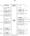
- FIG. 2 is a configuration diagram showing a control system of the automatic urine collection system S of FIG.
- the automatic urine collection system S includes a urine receiver R attached to a diaper (pad) D for temporarily receiving urine excreted from a patient M, and urine received by the urine receiver R. And an automatic urine collecting device 1 that automatically collects the blood through the tube T.
- the tube T is formed of a tube made of flexible silicone rubber or vinyl chloride. The tube T constitutes a part of a urine flow path for sucking urine received by the urine receiver R into the main tank 20.
- a receiver urine sensor S1 for detecting urine excreted from the patient M and a receiver stool sensor S2 for detecting feces excreted from the patient M are provided. Signals detected by the receiver urine sensor S1 and the receiver stool sensor S2 are transmitted to the control board 423 of the automatic urine collecting device 1.
- the receiver urine sensor S1 and the receiver stool sensor S2 are both sensors for detecting moisture, and are used separately for the receiver urine sensor S1 and the receiver stool sensor S2 by making a difference in installation location. .
- the automatic urine collecting device 1 includes a main tank portion 2 for collecting and storing urine sent from the urine receiver R through the tube T, and a main body portion 3 for holding the main tank portion 2. Configured.
- the automatic urine collecting apparatus 1 is provided with a control board 423 as shown in FIG.
- the control board 423 includes a control device 423a such as a CPU (Central Processing Unit), a nonvolatile memory 423b such as a ROM (Read Only Memory), and a volatile memory 423c such as a RAM (Random Access Memory).
- the nonvolatile memory 423b stores programs and data necessary for each control. And each process is implement
- the control device 423a includes a receiver urine sensor S1, a receiver stool sensor S2, a urine sensor S3, a nonvolatile memory 423b, a volatile memory 423c, a drive motor 53a for the suction pump 53, a battery, and a display lamp 511 for the operation panel unit 47.
- operation switches 516 to 518, an alarm 519 and the like are electrically connected.
- the control device 423a Based on signals transmitted from the receiver urine sensor S1, the receiver stool sensor S2, the urine sensor S3, the operation switches 516 to 518, and the like, the control device 423a performs the driving motor 53a of the suction pump 53, the operation panel unit 47, and the like. Control various devices.
- the urine sensor S3 includes a main tank infrared sensor S31, a main tank water level sensor S32, and a sub tank infrared sensor S33.
- the volatile memory 423c is detected by the receiver urine sensor S1, the receiver stool sensor S2, the non-volatile memory 423b, the volatile memory 423c, the main tank infrared sensor S31, the main tank water level sensor S32, and the sub tank infrared sensor S33. Recorded results are recorded.
- the volatile memory 423c stores an automatic urine collecting device ID, a user name, a user ID, a date and time, a detection result, and the like in association with each other.
- the control board 423 includes an external terminal 57, and can output operation history data (such as the number of urinations and detection times of various sensors) recorded in the volatile memory 423b to an external device such as a personal computer or a printer.
- operation history data such as the number of urinations and detection times of various sensors
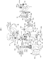
- FIGS. 3 is an exploded perspective view of the automatic urine collecting device 1 of FIG. 1
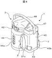
- FIG. 4 is a front perspective view of the automatic urine collecting device 1 of FIG. 1
- FIG. 5 is a rear perspective view of the automatic urine collecting device 1 of FIG. Is a longitudinal sectional view of the automatic urine collecting device 1 of FIG. 4
- FIG. 7 is a front perspective view of the automatic urine collecting device 1 of FIG. 4 with the main tank portion 2 taken out
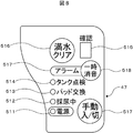
- FIG. 8 is an automatic urine collecting device 1 of FIG. It is a top view of the operation panel part 47.
- the main tank unit 2 includes the main tank 20, the urine discharge pipe 230, the intake stop means 231, the foam avoidance net 232, and the like.
- the main tank 20 constitutes a collection container that collects and collects urine received by the urine receiver R, and is formed on a main tank body 21 having a predetermined depth and an upper surface 21a of the main tank body 21. And a main tank lid 23 that seals the opening 22. Since the inside of the main tank body 21 is depressurized by the suction action of the suction pump 53, the main tank body 21 is formed in a substantially bottomed cylindrical shape in order to obtain a predetermined strength. In this embodiment, the main tank main body 21 has a maximum capacity of 1400 mL and an effective capacity (full water capacity) of 1000 mL.
- the upper surface 21a of the main tank main body 21 is formed in a substantially hemispherical shape having the center as an apex, and an opening 22 sealed by the main tank lid 23 is formed at the apex portion.
- the upper surface 21a is preferably integrally formed with other parts of the main tank body 21, but may be configured to be connected after being separately molded.
- the opening 22 is formed smaller than the diameter of the side surface 21b of the main tank body 21.
- the threaded portion 22 a raised along the edge of the opening 22 has a female thread that can be screwed with a male thread (not shown) on the inner periphery of the main tank lid 23.
- the main tank body 21 is formed of a resin material that simultaneously satisfies a weight that is easy to carry and a predetermined strength, such as a plastic typified by polycarbonate or polypropylene.
- the main tank main body 21 allows the user to grasp the volume of urine stored in the main tank main body 21 (hereinafter referred to as “the amount of urine” or “the amount of urine”) and can transmit infrared rays. It is made of a translucent resin material. When the main tank body 21 is made translucent, it is possible to consider the privacy of the user while making the urine volume visible from the outside of the main tank body 21, and when discarding urine. It can be confirmed how much the main tank 20 should be inclined.
- the main tank body 21 can be covered with the tank cover 44 in consideration of the privacy of the user. Since a tank urine volume confirmation window 44a is provided at the center of the tank cover 44, the urine volume in the main tank main body 21 can be visually recognized through the confirmation window 44a.
- the confirmation window 44a is formed of a transparent member or a simple hole.
- a handle 21c is formed on the side surface 21b of the main tank body 21 to assist the user in carrying it.
- the handle 21 c is also used for positioning when the main tank 20 is accommodated in the main body 3.
- the main tank lid 23 is a celestial cylindrical member for sealing the opening 22 of the main tank main body 21.
- a male screw (not shown) to which a female screw of a screw portion 22b provided in the opening 22 of the main tank main body 21 is screwed is formed.
- an inlet 23 a that communicates with the tube T and introduces urine into the main tank body 21, and an inlet 23 b that communicates with the suction pump 53 and sucks air in the main tank 20. And are formed.
- the introduction port 23a constitutes a part of the urine flow path
- the intake port 23b constitutes a part of the air flow path.
- a urine discharge pipe 230 for discharging urine introduced from the introduction port 23a into the main tank 20 is provided below the introduction port 23a located at the center of the main tank 20.
- the urine discharge pipe 230 is suspended from the main tank lid 23 downward. Further, the urine discharge pipe 230 communicates with the introduction port 23a and extends downward, and a T-shaped discharge pipe 230b that communicates with the lower end of the discharge conduit 230a and branches horizontally and opens in the opposite direction. And is configured.
- the width of the T-shaped discharge pipe 230b (distance between the openings on both sides) is set slightly smaller than the diameter of the opening 22 of the main tank 20.
- the flow rate of urine dripping can be slowed and dispersed at two locations. And it can be dripped so that the outer periphery in the main tank 20 may be approached. Thereby, scattering of urine can be eased, and the height of bubbles in the upper part of the collected urine can be lowered as a whole.
- the foam formed at the upper part of the urine is formed in two small ridges, so that the height of the ridge of the bubbles is higher than when one discharge port is provided. Can be reduced to less than half.
- an intake stop means 231 for stopping intake when the urine in the main tank 20 is full, and bubbles are sucked from the intake port 23b.
- a bubble avoidance net 232 is provided to prevent this from occurring.
- the intake air stopping means 231 includes a ball valve 231a for directly sealing the air inlet 23b, and a rod-shaped member having an upper end formed in a saucer shape, and a ball valve support member 231b for supporting the ball valve 231a at the upper end.
- a housing bottom cover 231c that holds the middle of the ball valve support member 231b so as to freely move up and down
- a float 231d that is connected to the lower end of the ball valve support member 231b, and that moves up and down as the water level changes
- a ball valve 231a includes a ball valve housing portion 23e having a space for moving up and down inside.
- the accommodating portion 23e is formed by a portion protruding downward from the peripheral edge of the air inlet 23b of the main tank lid 23. Note that a communication path that connects the air inlet 23b and the inside of the main tank 20 is formed in the housing bottom lid 231c or the housing 23e.
- inhalation stop means 23 when the urine water level becomes full (when the urine volume reaches the effective volume of 1000 mL), the float 231d is pushed upward, and the ball valve 231a is interposed via the ball valve support member 231b. Seals the air inlet 23b from below. That is, when the water is full, no further intake is performed, and the introduction of urine into the main tank 20 can be stopped. That is, since it is possible to prevent urine from being sucked from the intake port 23b when the water is full, the possibility that the suction pump 53 and the air flow path are contaminated with urine and the function of the suction pump 53 is reduced can be reduced. It is possible to prevent the generation of malodor from the portion.
- the intake stop means 231 constitutes a part of the main tank water level sensor S32.
- the main tank water level sensor includes a float 231d that rises when the urine water level in the main tank 20 rises, a ball valve 231a that closes the air inlet 23b of the air flow path by the float 231d rising, and a suction pump And a detecting means for detecting a current change of the driving motor 53a.
- the bubble avoidance net 232 is formed in a cylindrical shape so as to cover the intake port 23b and the intake stop means 231, and is suspended downward from the main tank lid 23. Such a bubble avoidance net 232 prevents the bubbles from reaching the intake port 23b even if the bubbles rise as the urine water level in the main tank 20 rises without hindering the operation of the intake air stopping means 231. Therefore, the possibility that the suction pump 53 and the air flow path are contaminated with bubbles and the function of the suction pump 53 is lowered can be reduced, and the generation of malodor from these portions can be prevented.
- the foam avoidance net 232 is configured to include a side surface 232a having a mesh entirely and a plate-shaped bottom surface 232b having no mesh.
- This mesh is composed of 40 to 50 meshes per inch.
- the plate-shaped bottom surface 232b is provided with a small-diameter hole 232c, the urine in the foam avoidance net 232 is removed when the foam avoidance net 232 is removed from the main tank body 21 together with the main tank lid 23. It can flow out into the main tank body 21 through the hole 232c.
- the main body 3 includes an openable / closable main body lid 41 having a urine flow path pipe 413 and an air flow path pipe 414, a tank storage section 42 for storing the main tank 20, and a main body bottom on which the main tank 20 is placed.
- the main body case is configured by the case forming the main body lid portion 41, the tank storage portion 42, the pump storage portion 45, and the main body bottom portion 43.
- the tank storage portion 42 includes a semi-cylindrical tank storage concave surface 42 a for storing the main tank 20. A part of the case forming the pump storage portion 45 is shared with the portion of the tank storage portion 42 forming the tank storage concave surface 42a.
- the main body lid 41 includes an upper frame 411 and a lower frame 412 serving as a base, a urine passage pipe 413 that can be connected to the introduction port 23a of the main tank lid 23, and air that can be connected to the intake port 23b of the main tank lid 23.
- a flow path pipe 414 and a lid coupling mechanism 415 for coupling the main tank lid 23 are mainly provided.
- connection ends of the urine passage pipe 413 and the air passage pipe 414 are connected to the introduction port 23a and the intake port 23b of the main tank lid 23, respectively.
- the portion 41 is open, the connection ends of the urine flow channel pipe 413 and the air flow channel pipe 414 are configured to be separated from the introduction port 23a and the intake port 23b.
- the upper frame 411 constitutes the upper wall and the side wall of the main body lid portion 41, and has a configuration in which a rim is formed over substantially the entire circumference from the edge of the flat upper wall toward the lower side.
- the size of the upper frame 411 in plan view is larger than that of the main tank lid 23, and the outer peripheral portion of the main tank lid 23 is located inside the edge of the upper frame 411.
- a plurality of rotation shafts are formed on the back side of the upper frame 411, and the plurality of rotation shafts are rotatably engaged with a plurality of rotation shaft grooves of the tank storage portion 42 to open and close the main body lid portion 41. is doing.
- the lower frame 412 constitutes the lower wall of the main body lid 41 and is basically formed in a shape corresponding to the upper frame 411.
- the urine passage pipe 413 constitutes a urine passage together with the tube T, the introduction port 23 a and the urine discharge pipe 230. is doing.
- This urine flow path is a flow path that connects the inner space of the urine receiver R and the inner space of the main tank 20.
- the air flow channel pipe 414 includes a first air flow channel conduit 414 a disposed in the main body lid portion 41 and a second air flow channel conduit 414 b disposed on the back surface of the main body back cover 46.
- One end of the first air passage conduit 414 a is connected to the air inlet 23 b of the main tank lid 23, and the other end is connected to the sub tank lid 62 of the sub tank 6.
- the second air flow path conduit 414 b has one end connected to the sub tank lid 62 and the other end connected to the suction pump 53.
- the air flow path pipe 414 forms an air flow path together with the intake port 23 b and the sub tank 6. This air flow path is a flow path that connects the inner space of the main tank 20 and the suction pump 53.
- the air passage pipe 414 and the sub tank 6 are installed so as to be removable from the main body 3 and can be easily maintained.
- the components of the first air flow channel conduit 414a, the second air flow channel conduit 414b, the sub tank main body 61, and the sub tank lid 62 can be removed, so that the inside thereof can be easily cleaned.
- the lid coupling mechanism 415 is formed on the main tank lid 23 by connecting the main body lid portion 41 and the main tank lid 23 to the urine passage pipe 413 and the air passage pipe 414 formed on the main body lid portion 41.
- the inlet 23a and the inlet 23b are connected.
- the tank storage section 42 includes a semi-cylindrical tank storage concave surface 42a for storing the main tank 20, it is possible to prevent the main tank 20 from falling over when the balance is lost.
- the tank housing concave surface 42 a has a shape that follows the shape of the side surface 21 b of the main tank 20.
- the tank storage unit 42 stores a main tank infrared sensor S31, a control board 423, and a battery.
- the main tank infrared sensor S31 is a main tank urine sensor capable of detecting bubbles formed in the upper part of the urine collected in the main tank 20, and is opposed to both sides of the main tank 20 via the main tank 20.
- the light emitting unit 421 and the light receiving unit 422 are arranged in this manner.
- the light emitting unit 421 and the light receiving unit 422 are installed so as to face the inside of the tank housing concave surface 42a from the hole formed in the tank housing concave surface 42a.
- the light emitting unit 421 and the light receiving unit 422 are arranged so as to be horizontally opposed to each other with a predetermined height.
- the light emitting unit 421 emits infrared rays, and the light receiving unit 422 receives the infrared rays.
- the main tank infrared sensor S31 can detect urine bubbles.
- the main tank infrared sensor S31 can detect urine.
- the urine detection position is set to be equal to or less than the effective capacity (full capacity) of the main tank body 21 (for example, 800 mL with respect to an effective capacity of 1000 mL).
- the main body bottom portion 43 has a shape corresponding to the bottom surface 21d of the main tank 20, and the main tank 20 is stably placed thereon.
- An escape recess 43a corresponding to the handle 21c of the main tank 20 is formed at the upper edge of the main body bottom 43, so that the placement position of the main tank 20 is automatically determined.
- a fall prevention portion 43b extending rearward is provided on the back surface of the main body bottom portion 43. This overturn prevention unit 43b is for preventing the automatic urine collecting device 1 from overturning.
- the suction pump 53 is mainly stored in the pump storage unit 45.
- the suction pump 53 is not particularly limited as long as it can suck air, but can be realized by, for example, a rotary pump.
- the rotary pump is a pump that sucks air in the main tank 20 by rotating a pair of rotors, and has a small size, a large suction force, and a quiet driving sound. .
- the suction pump 53 includes a pump main body 53a, a drive motor 53b, a vibration absorber 53c, a pump connecting member 53d, and a pump case 53e, and is installed in a replaceable manner. As a result, if the suction pump 53 breaks down, it can be easily replaced.
- the suction port of the pump body 53a is connected to the air passage pipe 414 and the air discharge pipe 54 via the pump connection member 53d, and the exhaust port of the pump body 53a is connected to the air discharge pipe 54 via the pump connection member 53d. Yes.
- the air discharge pipe 54 communicates with the inlet of the deodorizing filter 7. Therefore, the exhaust from the suction pump 53 is introduced into the deodorizing filter 7.
- a drive motor 53b is disposed below the suction pump main body 53a, and a rubber-like vibration absorber (elastic member) 53c is disposed below the drive motor 53b.
- a rubber-like vibration absorber (elastic member) 53c is disposed below the drive motor 53b.
- the vibration absorber 53c the vibration generated from the pump main body 53a and the drive motor 53b is mainly absorbed by the vibration absorber 53c.
- the pump body 53a, the drive motor 53b, the vibration absorber 53c, and the pump connecting member 53d are housed in a pump case 53e that is divided into two parts.
- the upper part of the pump storage part 45 includes an attachment part 45a for attaching the operation panel part 47 and a terminal accommodating part 45b for accommodating the external terminal 57.
- the operation panel unit 47 includes an operation panel 47a, a panel base 47b, and a control board 423.
- the operation panel 47a is a seal-like member having a character appropriately provided on the surface thereof, and is attached to the upper surface of the panel base 47b.
- a control board 423 is disposed in the panel base 47b. The control board 423 is connected to the receiver urine sensor S1 and the receiver stool sensor S2 through the sensor cable 424.
- the control board 423 is provided with operation switches, display lamps, and the like corresponding to characters appropriately applied to the operation panel 47a, and the operation and display of these operation switches and display lamps can be performed on the panel base 47b. Equipped with a relief part to do.
- the operation panel unit 47 has a display lamp 511 indicating ON / OFF of the power supply, a display lamp 512 indicating that urine collection is being performed by the suction pump 53, a display lamp 513 for warning pad replacement, and a warning for tank inspection.
- a display lamp 514 for identifying, displaying various states detected by various sensors, a 7-segment display lamp 515, a full water clear switch 516 for the user to release an error state such as full water, and the suction pump 53 manually.
- a manual on / off switch 517 for turning on and off the motor 53b and a temporary mute switch 518 for temporarily stopping the output of the alarm 519 are provided.
- the sub tank 6 Since the sub tank 6 is connected in the middle of the air flow path pipe 414, in the unlikely event that urine flows into the air flow path pipe 414 from the intake port 23b, this flowed urine can be stored in the sub tank 6. . Moreover, the inside of the air inflow pipe 414 and the sub tank 6 may be condensed due to steam of urine, and this condensed water can also be stored in the sub tank 6. Therefore, it is possible to reduce the possibility that the suction pump 53 is contaminated with urine or condensed water and the function is lowered. And since the subtank 6 is detachably installed from the main-body part 3, when it is contaminated with urine, it can be removed and cleaned.
- the sub tank 6 includes a vertically long and cylindrical sub tank main body 61 and a sub tank lid 62 that seals an opening formed on the upper surface of the sub tank main body 61.
- the sub tank main body 61 is formed in a substantially bottomed cylindrical shape in order to obtain a predetermined strength because the inside thereof is depressurized by the suction action of the suction pump 53.
- the effective (full water) capacity of the sub tank main body 61 is 50 mL.
- the main tank main body 21 is formed of a translucent resin material, such as polycarbonate or polypropylene, which allows the user to grasp that urine has flowed into the inside and can transmit infrared rays.
- the main body back cover 46 is provided with an infrared sensor S33 for sub tank.
- the sub-tank infrared sensor S33 is a sub-tank urine sensor that can detect bubbles flowing into the sub-tank 6, and includes a light emitting unit 461 and a light receiving unit 462 disposed on both sides of the sub tank 6 so as to face each other through the sub tank 6. It is prepared for.
- the light emitting unit 461 and the light receiving unit 462 are installed so as to protrude rearward from the back surface of the main body back cover 46.
- the light emitting unit 461 and the light receiving unit 462 are disposed so as to be horizontally opposed to each other with a predetermined height.
- the light emitting unit 461 emits infrared rays, and the light receiving unit 462 receives the infrared rays.
- the sub-tank infrared sensor S33 can detect urine bubbles.
- the sub tank infrared sensor S33 can detect urine.
- the urine detection position is set to be equal to or less than the effective (full water) capacity of the sub tank main body 61 (for example, 20 mL with respect to the effective capacity of 50 mL). This is because even if the sub-tank infrared sensor detects the urine water level and stops the suction pump 53, urine may further flow in until the negative pressure inside the sub-tank 6 returns to the atmospheric pressure. It is desirable to set the water level.
- the deodorizing filter 7 is detachably mounted on the fall prevention portion 43b, and the sub tank 6 is arranged in the space above the deodorizing filter 7. With this arrangement, the entire apparatus can be made compact.
- the deodorizing filter 7 is installed horizontally in contact with the back side of the lower end of the main body back cover 46 constituting the main body case.
- the deodorizing filter 7 is provided with an inlet 7a at an upper surface portion near one side end portion in the left-right direction, an outlet 7b is provided at a rear surface portion near the other end portion, and a deodorizing member is accommodated therein.
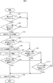
- FIG. 9 is a flowchart showing an operation example of the automatic urine collecting device 1 of FIG.
- step S1 it is determined whether the main tank infrared sensor S31 detects urine in the main tank 20 (step S1). As described above, the detection of urine by the main tank infrared sensor S31 is performed based on the presence or absence of bubbles rising as the urine water level in the main tank 20 increases.
- step S2 When the main tank infrared sensor S31 detects bubbles in the main tank 20 in step S1, the display lamp 514 that warns the inspection of the main tank 20 blinks and a warning is given by the alarm 519 (step S2). As a result, the user can grasp the state of bubbles in the main tank 20, so that the bubbles in the main tank 20 are sucked into the suction pump 53 by discarding the urine in the main tank 20. Can be prevented. Note that the flow proceeds to step S2 also when the urine water level in the main tank 20 reaches the position of the main tank infrared sensor S31 without detecting the bubbles and the main tank infrared sensor S31 detects it.
- step 3 it is determined whether the suction pump 53 is ON (step 3).
- the suction pump 53 is turned on when the receiver urine sensor S1 is turned on to automatically turn on the suction pump 53 (automatic operation), or the manual on / off switch 517 is pushed to manually turn on the suction pump 53. Turns on or applies to all cases.
- the suction pump 53 is driven for a predetermined time, and the air in the main tank 20 is driven by the drive of the suction pump 53.
- the air inlet 23b and the air passage pipe 414 of the main body lid portion 41 the inside of the main tank 20 is decompressed.
- step S4 it is determined whether the sub tank infrared sensor S33 has detected urine in the sub tank 6 (step S4). As described above, the detection of urine by the sub tank infrared sensor S33 is performed based on the presence or absence of bubbles in the sub tank 6.
- step S5 When the bubble in the sub tank 6 is detected by the sub tank infrared sensor S33 in step S4, the suction pump 53 is stopped (step S5). This can reduce the possibility that the suction pump 53 is contaminated with bubbles and the function of the suction pump 53 is lowered.
- step S5 the suction pump 53 is stopped, and at the same time, in order to warn the inspection of the sub tank 6, the display lamp 515 blinks and the alarm 519 is sounded.
- step S6 a specific number or symbol is displayed on the display lamp 515 in order to identify the type of warning. Then, it is determined that the user turns on the full water clear switch (step S6). When the full water clear switch is turned on, the process returns to step S4 while the suction pump 53 is stopped until the detection of the sub tank infrared sensor S33 is released. Continue warning by 515 and alarm 519.
- step S7 it is determined whether the main tank water level sensor S32 has detected urine in the main tank 20 (step S7).
- the urine is detected by the main tank water level sensor S32 by detecting whether the urine water level in the main tank 20 has reached the full level. If the main tank water level sensor S32 detects full water in step S7, the suction pump 53 is stopped (step S8).
- step S8 the suction pump 53 is stopped and at the same time, in order to warn the inspection of the main tank 20, the display lamp 515 blinks and the alarm 519 is sounded. At this time, a specific number or symbol is displayed on the display lamp 515 in order to identify the type of warning.
- step S9 it is determined that the user turns on the full water clear switch (step S9), and if the full water clear switch is turned on, the process proceeds to step S10 to determine whether the main tank infrared sensor S31 is detected (step S10). This is to prevent the urine stored in the main tank from being released without being discarded. If the main tank infrared sensor S31 is detected, the process returns to step S8, and the warning by the display lamp 515 and the alarm 519 is continued while the suction pump 53 is stopped until the detection of the main tank infrared sensor S31 is released.
- the suction pump 53 is driven (step S11), and it is re-determined whether the main tank water level sensor S32 is detected (step S12).
- the suction pump 53 is driven because the main tank water level sensor S32 detects a full water level by detecting a current change in the drive motor 53b of the suction pump 53.
- the flow returns to step S8 to stop the suction pump 53 and continue the warning by the display lamp 515 and the alarm 519. If the main tank water level sensor S32 does not detect in step S12, the suction pump 53 is stopped to return to the initial control (step S13).
- the suction pump 53 is driven for the detection determination of the main tank water level sensor in step S12, but this time is suitably about 2 seconds.
- the warnings generated by the display lamps 514 and 515 and the alarm 519 issued in steps S2, S5, and S8 are released at the same time as the respective states are released.
- the light emitting units 421 and 461 used in the main tank infrared sensor S31 and the sub tank infrared sensor S33 may emit light continuously or may be controlled to emit light intermittently (for example, in a pulse form). . By emitting light intermittently, the lifetime of the light-emitting element can be extended compared to continuous light emission.
- the amount of infrared rays from the outside can be reduced. It is possible to detect and warn of a state where the sensor is not working properly because it is too much.
- Light receiving part 423 ... Control board, 423a ... Control device, 423b ... Non-volatile memory, 423c ... Volatile memory, 511 to 515 ... Indicator lamp, 516 ... Full water clear switch, 517 ... Manual on / off switch, 518 alarm, 519 ... Temporary mute switch, D ... Diaper, R ... Urine receiver, S1 ... Urine for receiver Sensor, S2 ... Stool sensor for receiver, S31 ... Infrared sensor for main tank, S32 ... Water level sensor for main tank , Infrared sensor, T ... tube for S33 ... the sub-tank.
Landscapes
- Health & Medical Sciences (AREA)
- Heart & Thoracic Surgery (AREA)
- Life Sciences & Earth Sciences (AREA)
- Veterinary Medicine (AREA)
- Public Health (AREA)
- General Health & Medical Sciences (AREA)
- Animal Behavior & Ethology (AREA)
- Biomedical Technology (AREA)
- Vascular Medicine (AREA)
- Engineering & Computer Science (AREA)
- Epidemiology (AREA)
- Orthopedic Medicine & Surgery (AREA)
- Nursing (AREA)
- Anesthesiology (AREA)
- Hematology (AREA)
- Physics & Mathematics (AREA)
- General Physics & Mathematics (AREA)
- Orthopedics, Nursing, And Contraception (AREA)
- Investigating Or Analysing Biological Materials (AREA)
- Sampling And Sample Adjustment (AREA)
Abstract
Description
(1)前記メインタンクに溜められた尿の廃棄を警告するための報知手段を備え、前記メインタンクは前記本体ケースに着脱可能に設置され、前記制御装置は前記メインタンク用赤外線センサの検出結果に基づいて前記報知手段を制御すること。
(2)前記(1)において、操作スイッチ及び表示ランプを配置した操作パネルを前記本体ケースに備え、前記報知手段は点滅して警告する前記表示ランプと音で警告するアラームとで構成され、前記操作スイッチは前記アラームの動作を停止する一時消音スイッチを備えていること。
(3)前記本体ケースはタンク収納凹部を有し、前記メインタンクは、前記タンク収納凹部に着脱可能に設置されると共に、赤外線を透過する半透明の樹脂材料で形成され、前記メインタンク用赤外線センサは前記メインタンクの両側に当該メインタンクを介して対向するように配置された発光部及び受光部を備えていること。
(4)前記尿センサは、前記メインタンク用赤外線センサと、前記メインタンクの尿の水位を検出するメインタンク用水位センサとを備えていること。
(5)前記(4)において、前記メインタンク用水位センサは、前記メインタンク内の尿の水位が上昇すると浮き上がるフロートと、前記フロートの浮き上がりにより前記空気流路の吸気口を閉鎖するボール弁と、前記吸引ポンプの駆動モータの電流変化を検知する検知手段とで構成されていること。
(6)前記(4)または(5)において、前記メインタンクに溜められた尿の廃棄を警告するための報知手段を備え、前記メインタンクは前記本体ケースに着脱可能に設置され、前記制御装置は、前記メインタンク用赤外線センサの検出結果に基づいて前記報知手段を制御すると共に、前記メインタンク用水位センサの検出結果に基づいて前記吸引ポンプの運転を停止または前記報知手段による警告を発するように制御すること。
(7)前記空気流路の途中に当該空気流路に流入した尿を溜めるサブタンクを備えていること。
(8)前記(7)において、前記尿センサは、前記メインタンク用赤外線センサと、前記サブタンクの尿を検出するサブタンク用センサとを備えていること。
(9)前記(8)において、前記サブタンク用センサは前記サブタンク内に流入された泡を検出可能なサブタンク用赤外線センサで構成されていること。
(10)前記(9)において、前記サブタンクは赤外線を透過する半透明の樹脂材料で形成され、前記サブタンク用赤外線センサは前記サブタンクの両側に当該メインタンクを介して対向するように配置された発光部及び受光部を備えていること。
(11)前記(8)において、前記メインタンクに溜められた尿の廃棄を警告するための報知手段を備え、前記メインタンクは前記本体ケースに着脱可能に設置され、前記制御装置は、前記メインタンク用赤外線センサの検出結果に基づいて前記報知手段による警告を発するように制御すると共に、前記サブタンク用センサの検出結果に基づいて前記吸引ポンプの運転を停止するように制御すること。
(12)前記メインタンクは、尿を溜めるメインタンク本体と、前記メインタンク本体の上面中央部に着脱可能に設置されると共に前記尿流路及び前記空気流路の一部を構成する開口部を隣接して設けたメインタンク蓋と備え、前記尿流路は前記メインタンク内で水平方向に分岐され反対方向に開口されたT字吐出管を備えていること。
(13)前記メインタンク内に開口する前記空気流路の吸気口を覆うように泡避けネットを備えていること。
(14)前記(13)において、前記尿センサは、前記メインタンク用赤外線センサと、前記メインタンクに溜められた尿の水位を検出するメインタンク用水位センサとを備え、前記メインタンク用水位センサは、前記メインタンク内の尿の水位が上昇すると浮き上がるフロートと、前記フロートの浮き上がりにより前記空気流路の吸気口を閉鎖するボール弁とを備え、前記泡避けネットは、前記空気流路の吸気口、前記フロート及び前記ボール弁を覆うように筒状に形成されていること。
(15)前記吸引ポンプの排気側に脱臭フィルタを備えていること。
(16)前記(15)において、前記空気流路の途中に当該空気流路に流入した尿を溜めるサブタンクを備え、前記脱臭フィルタは前記本体ケースの背面下部に横長に設置され、前記サブタンクは前記本体ケースの背面の前記脱臭フィルタの上方空間に設置されていること。
ステップS10でメインタンク用赤外線センサS31が検知していない場合は、吸引ポンプ53を駆動し(ステップS11)、メインタンク用水位センサS32が検知するか再判定する(ステップS12)。ここで吸引ポンプ53を駆動するのは、本実施例ではメインタンク用水位センサS32は吸引ポンプ53の駆動モータ53bの電流変化を検出して満水を検知するためである。そしてステップS12でメインタンク用水位センサS32が再び検知したらステップS8に戻り吸引ポンプ53を停止し表示ランプ515とアラーム519による警告を継続する。
ステップS12でメインタンク用水位センサS32が検知しない場合には、吸引ポンプ53を停止して始めの制御に戻る(ステップS13)。ここでステップS11からS13までの間は、ステップS12でのメインタンク用水位センサの検知判定のため吸引ポンプ53を駆動することになるが、この時間は2秒間程度が適当である。
なお、ステップS2、S5、S8で発した表示ランプ514、515とアラーム519による警告は、各々の状態が解除されると同時に警告も解除する。
また、メインタンク用赤外線センサS31およびサブタンク用赤外線センサS33で使用する発光部421、461では、連続的に発光しても良いが、間欠的(例えばパルス状)に発光するよう制御しても良い。間欠的に発光することで、連続的に発光するのに比べて発光素子の寿命を延ばすことができる。さらに、受光部422、462で非発光時の受光量を検出することにより、外部からの赤外線(例えば太陽光からの赤外線や室内灯からの赤外線)の量が発光部421、461から発する赤外線の量よりも多過ぎてセンサが正常に働かない状態を検知して警告することができる。
Claims (19)
- 尿レシーバで受けた尿を回収して溜めておくメインタンクと、
前記メインタンクを支持する本体ケースと、
空気流路を通して前記メインタンク内の空気を吸引することにより、前記尿レシーバで受けた尿を尿流路を通して前記メインタンク内に吸入する吸引ポンプと、
尿を検出する尿センサと、
前記尿センサの検出結果に基づいて制御指令を出力する制御装置と、を備えた自動収尿装置において、
前記尿センサは前記メインタンクに溜められた尿の上部に存在する泡を検出可能なメインタンク用赤外線センサを備えている
ことを特徴とする自動収尿装置。 - 請求項1において、
前記メインタンクに溜められた尿の廃棄を警告するための報知手段を備え、
前記メインタンクは前記本体ケースに着脱可能に設置され、
前記制御装置は前記メインタンク用赤外線センサの検出結果に基づいて前記報知手段を制御する
ことを特徴とする自動収尿装置。 - 請求項2において、
操作スイッチ及び表示ランプを配置した操作パネルを前記本体ケースに備え、
前記報知手段は点滅して警告する前記表示ランプと音で警告するアラームとで構成され、
前記操作スイッチは前記アラームの動作を停止する一時消音スイッチを備えている
ことを特徴とする自動収尿装置。 - 請求項1において、
前記本体ケースはタンク収納凹部を有し、
前記メインタンクは、前記タンク収納凹部に着脱可能に設置されると共に、赤外線を透過する半透明の樹脂材料で形成され、
前記メインタンク用赤外線センサは前記メインタンクの両側に当該メインタンクを介して対向するように配置された発光部及び受光部を備えている
ことを特徴とする自動収尿装置。 - 請求項1において、
前記尿センサは、前記メインタンク用赤外線センサと、前記メインタンクの尿の水位を検出するメインタンク用水位センサとを備えている
ことを特徴とする自動収尿装置。 - 請求項5において、
前記メインタンク用水位センサは、前記メインタンク内の尿の水位が上昇すると浮き上がるフロートと、前記フロートの浮き上がりにより前記空気流路の吸気口を閉鎖するボール弁と、前記吸引ポンプの駆動モータの電流変化を検知する検知手段とで構成されている
ことを特徴とする自動収尿装置。 - 請求項5または6において、
前記メインタンクに溜められた尿の廃棄を警告するための報知手段を備え、
前記メインタンクは前記本体ケースに着脱可能に設置され、
前記制御装置は、前記メインタンク用赤外線センサの検出結果に基づいて前記報知手段を制御すると共に、前記メインタンク用水位センサの検出結果に基づいて前記吸引ポンプの運転を停止または前記報知手段による警告を発するように制御する
ことを特徴とする自動収尿装置。 - 請求項1において、
前記空気流路の途中に当該空気流路に流入した尿を溜めるサブタンクを備えている
ことを特徴とする自動収尿装置。 - 請求項8において、
前記尿センサは、前記メインタンク用赤外線センサと、前記サブタンクの尿を検出するサブタンク用センサとを備えている
ことを特徴とする自動収尿装置。 - 請求項9において、
前記サブタンク用センサは前記サブタンク内に流入された泡を検出可能なサブタンク用赤外線センサで構成されている
ことを特徴とする自動収尿装置。 - 請求項10において、
前記サブタンクは赤外線を透過する半透明の樹脂材料で形成され、
前記サブタンク用赤外線センサは前記サブタンクの両側に当該メインタンクを介して対
向するように配置された発光部及び受光部を備えている
ことを特徴とする自動収尿装置。 - 請求項9において、
前記メインタンクに溜められた尿の廃棄を警告するための報知手段を備え、
前記メインタンクは前記本体ケースに着脱可能に設置され、
前記制御装置は、前記メインタンク用赤外線センサの検出結果に基づいて前記報知手段による警告を発するように制御すると共に、前記サブタンク用センサの検出結果に基づいて前記吸引ポンプの運転を停止するように制御する
ことを特徴とする自動収尿装置。 - 請求項1において、
前記メインタンクは、尿を溜めるメインタンク本体と、前記メインタンク本体の上面中央部に着脱可能に設置されると共に前記尿流路及び前記空気流路の一部を構成する開口部を隣接して設けたメインタンク蓋と備え、
前記尿流路は前記メインタンク内で水平方向に分岐され反対方向に開口されたT字吐出管を備えている
ことを特徴とする自動収尿装置。 - 請求項1において、
前記メインタンク内に開口する前記空気流路の吸気口を覆うように泡避けネットを備えている
ことを特徴とする自動収尿装置。 - 請求項14において、
前記尿センサは、前記メインタンク用赤外線センサと、前記メインタンクに溜められた尿の水位を検出するメインタンク用水位センサとを備え、
前記メインタンク用水位センサは、前記メインタンク内の尿の水位が上昇すると浮き上がるフロートと、前記フロートの浮き上がりにより前記空気流路の吸気口を閉鎖するボール弁とを備え、
前記泡避けネットは、前記空気流路の吸気口、前記フロート及び前記ボール弁を覆うように筒状に形成されている
ことを特徴とする自動収尿装置。 - 請求項1において、
前記吸引ポンプの排気側に脱臭フィルタを備えている
ことを特徴とする自動収尿装置。 - 請求項16において、
前記空気流路の途中に当該空気流路に流入した尿を溜めるサブタンクを備え、
前記脱臭フィルタは前記本体ケースの背面下部に横長に設置され、
前記サブタンクは前記本体ケースの背面の前記脱臭フィルタの上方空間に設置されている
ことを特徴とする自動収尿装置。 - 尿レシーバで受けた尿を回収して溜めておくメインタンクと、
前記メインタンクを支持する本体ケースと、
空気流路を通して前記メインタンク内の空気を吸引することにより、前記尿レシーバで受けた尿を尿流路を通して前記メインタンク内に吸入する吸引ポンプと、
尿を検出する尿センサと、
前記尿センサの検出結果に基づいて制御指令を出力する制御装置と、を備えた自動収尿装置において、
前記空気流路の途中に当該空気流路に流入した尿を溜めるサブタンクを備え、
前記尿センサは、前記メインタンクに溜められた尿を検出するメインタンクセンサと、前記サブタンクの尿を検出するサブタンク用センサとを備えている
ことを特徴とする自動収尿装置。 - 尿レシーバで受けた尿を回収して溜めておくメインタンクと、
前記メインタンクを支持する本体ケースと、
空気流路を通して前記メインタンク内の空気を吸引することにより、前記尿レシーバで受けた尿を尿流路を通して前記メインタンク内に吸入する吸引ポンプと、
尿を検出する尿センサと、
前記尿センサの検出結果に基づいて制御指令を出力する制御装置と、を備えた自動収尿装置において、
前記メインタンク内に開口する前記空気流路の吸気口を覆うように泡避けネットを備え、
前記尿センサは、前記メインタンクに溜められた尿を検出するメインタンクセンサと、前記メインタンクの尿の水位を検出するメインタンク用水位センサとを備え、
前記泡避けネットは前記空気流路の吸気口及び前記メインタンク用水位センサのフロートの両方を覆うように筒状に形成されている
ことを特徴とする自動収尿装置。
Priority Applications (3)
| Application Number | Priority Date | Filing Date | Title |
|---|---|---|---|
| EP09838739.2A EP2389908A4 (en) | 2009-01-20 | 2009-12-04 | AUTOMATIC URINE COLLECTION DEVICE |
| US13/144,961 US20110265889A1 (en) | 2009-01-20 | 2009-12-04 | Automatic Urine Collecting Device |
| SG2011052438A SG173067A1 (en) | 2009-01-20 | 2009-12-04 | Automatic urine collecting device |
Applications Claiming Priority (2)
| Application Number | Priority Date | Filing Date | Title |
|---|---|---|---|
| JP2009-009776 | 2009-01-20 | ||
| JP2009009776A JP5356838B2 (ja) | 2009-01-20 | 2009-01-20 | 自動収尿装置 |
Publications (1)
| Publication Number | Publication Date |
|---|---|
| WO2010084545A1 true WO2010084545A1 (ja) | 2010-07-29 |
Family
ID=42355623
Family Applications (1)
| Application Number | Title | Priority Date | Filing Date |
|---|---|---|---|
| PCT/JP2009/006635 Ceased WO2010084545A1 (ja) | 2009-01-20 | 2009-12-04 | 自動収尿装置 |
Country Status (7)
| Country | Link |
|---|---|
| US (1) | US20110265889A1 (ja) |
| EP (1) | EP2389908A4 (ja) |
| JP (1) | JP5356838B2 (ja) |
| KR (1) | KR20110104969A (ja) |
| SG (1) | SG173067A1 (ja) |
| TW (1) | TW201028132A (ja) |
| WO (1) | WO2010084545A1 (ja) |
Cited By (4)
| Publication number | Priority date | Publication date | Assignee | Title |
|---|---|---|---|---|
| JP2013212352A (ja) * | 2012-11-30 | 2013-10-17 | Saito Keiko | 排泄物処理装置及びその方法 |
| TWI614006B (zh) * | 2016-12-23 | 2018-02-11 | 長庚學校財團法人長庚科技大學 | 尿液收集裝置 |
| CN111481751A (zh) * | 2020-04-20 | 2020-08-04 | 安徽医科大学第一附属医院 | 用于气管切开患者吸痰的防护装置 |
| WO2023010716A1 (zh) * | 2021-08-02 | 2023-02-09 | 郭俊芳 | 一种密封性强的妇产科护理用接尿装置 |
Families Citing this family (84)
| Publication number | Priority date | Publication date | Assignee | Title |
|---|---|---|---|---|
| US8882678B2 (en) | 2009-03-13 | 2014-11-11 | Atrium Medical Corporation | Pleural drainage system and method of use |
| JP5833628B2 (ja) * | 2010-04-08 | 2015-12-16 | 株式会社キュラコCURACO, Inc. | 自動排泄物処理装置およびその制御方法 |
| JP5254498B1 (ja) * | 2012-04-02 | 2013-08-07 | 齋藤 恵子 | 排泄物処理装置 |
| CN104720955B (zh) * | 2012-04-02 | 2017-01-18 | 斋藤惠子 | 排泄物处理装置及其方法 |
| CN104688403B (zh) * | 2012-04-02 | 2017-04-12 | 斋藤惠子 | 排泄物处理装置及其方法 |
| JP5368621B2 (ja) * | 2012-11-30 | 2013-12-18 | 齋藤 恵子 | 排泄物処理装置 |
| US11806266B2 (en) | 2014-03-19 | 2023-11-07 | Purewick Corporation | Apparatus and methods for receiving discharged urine |
| US10952889B2 (en) | 2016-06-02 | 2021-03-23 | Purewick Corporation | Using wicking material to collect liquid for transport |
| US11376152B2 (en) | 2014-03-19 | 2022-07-05 | Purewick Corporation | Apparatus and methods for receiving discharged urine |
| US10226376B2 (en) | 2014-03-19 | 2019-03-12 | Purewick Corporation | Apparatus and methods for receiving discharged urine |
| US10390989B2 (en) | 2014-03-19 | 2019-08-27 | Purewick Corporation | Apparatus and methods for receiving discharged urine |
| WO2015192108A1 (en) * | 2014-06-12 | 2015-12-17 | Kostov Konstantin | Device and method for monitoring irregular liquid flow rates |
| DE102014226890A1 (de) * | 2014-12-23 | 2016-06-23 | Paul Hartmann Ag | Vorrichtung zur Bereitstellung von Unterdruck für medizinische Anwendungen |
| US10940242B2 (en) * | 2015-07-31 | 2021-03-09 | Dornoch Medical Systems, Inc. | Medical waste fluid collection and disposal system |
| JP6839452B2 (ja) | 2016-02-18 | 2021-03-10 | ユーアール24 テクノロジー,エルエルシー | 自動尿採取器−分析器 |
| US10682124B2 (en) | 2016-02-18 | 2020-06-16 | Ur24 Technology, Llc | Automated collection and analysis of body fluids |
| US10690655B2 (en) | 2016-02-18 | 2020-06-23 | Ur24 Technology, Llc | Automated urine collector-analyzer |
| US10376406B2 (en) | 2016-07-27 | 2019-08-13 | Purewick Corporation | Male urine collection device using wicking material |
| US10973678B2 (en) | 2016-07-27 | 2021-04-13 | Purewick Corporation | Apparatus and methods for receiving discharged urine |
| US11617568B2 (en) | 2016-12-29 | 2023-04-04 | Jay K. Joshi | Fluid output measurement device and method |
| WO2018144463A1 (en) | 2017-01-31 | 2018-08-09 | Purewick Corporation | Apparatus and methods for receiving discharged urine |
| EP3787571B1 (en) | 2018-05-01 | 2022-06-01 | Purewick Corporation | Fluid collection garments |
| US11944740B2 (en) | 2018-05-01 | 2024-04-02 | Purewick Corporation | Fluid collection devices, related systems, and related methods |
| JP7072084B2 (ja) | 2018-05-01 | 2022-05-19 | ピュアウィック コーポレイション | 流体収集装置、関連システム、及び関連方法 |
| AU2019262945B2 (en) | 2018-05-01 | 2022-08-25 | Purewick Corporation | Fluid collection devices and methods of using the same |
| AU2019262939A1 (en) | 2018-05-01 | 2020-11-26 | Purewick Corporation | Fluid collection devices, systems, and methods |
| EP3787569B1 (en) | 2018-05-01 | 2025-07-16 | Purewick Corporation | Fluid collection devices and systems |
| CA3143904C (en) | 2019-06-21 | 2023-11-28 | Purewick Corporation | Fluid collection devices including a base securement area, and related systems and methods |
| ES2961269T3 (es) | 2019-07-11 | 2024-03-11 | Purewick Corp | Dispositivos y sistemas de recogida de líquido |
| WO2021016026A1 (en) | 2019-07-19 | 2021-01-28 | Purewick Corporation | Fluid collection devices including at least one shape memory material |
| KR102241002B1 (ko) * | 2019-09-23 | 2021-04-20 | 고려대학교 산학협력단 | 체액 배출량 측정 장치 |
| EP4051190B1 (en) | 2019-10-28 | 2024-05-22 | Purewick Corporation | Fluid collection assemblies including a sample port |
| EP4559443A3 (en) | 2020-01-03 | 2025-06-18 | Purewick Corporation | Urine collection devices having a relatively wide portion and an elongated portion and related methods |
| CN111228593B (zh) * | 2020-03-13 | 2024-09-06 | 广东省人民医院(广东省医学科学院) | 一种高负压引流瓶引流量精确测量装置 |
| WO2021188817A1 (en) | 2020-03-19 | 2021-09-23 | Purewick Corporation | Fluid collection assemblies including one or more movement enhancing features |
| US12521288B2 (en) | 2020-03-26 | 2026-01-13 | Purewick Corporation | Multi-layer urine capture device and related methods |
| WO2021207621A1 (en) | 2020-04-10 | 2021-10-14 | Purewick Corporation | Fluid collection assemblies including one or more leak prevention features |
| US12465514B2 (en) | 2020-04-17 | 2025-11-11 | Purewick Corporation | Fluid collection devices, systems, and methods securing a protruding portion in position for use |
| WO2021211801A1 (en) | 2020-04-17 | 2021-10-21 | Purewick Corporation | Fluid collection assemblies including a fluid impermeable barrier having a sump and a base |
| US12472090B2 (en) | 2020-04-17 | 2025-11-18 | Purewick Corporation | Female external catheter devices having a urethral cup, and related systems and methods |
| US12491104B2 (en) | 2020-04-20 | 2025-12-09 | Purewick Corporation | Fluid collection devices adjustable between a vacuum-based orientation and a gravity-based orientation, and related systems and methods |
| US11311405B2 (en) | 2020-05-22 | 2022-04-26 | Ur24Technology, Inc. | Methods and apparatus for collecting body fluids |
| US12048643B2 (en) | 2020-05-27 | 2024-07-30 | Purewick Corporation | Fluid collection assemblies including at least one inflation device and methods and systems of using the same |
| USD969308S1 (en) | 2020-05-28 | 2022-11-08 | Ur24Technology, Inc. | Fluid collection apparatus |
| USD967409S1 (en) | 2020-07-15 | 2022-10-18 | Purewick Corporation | Urine collection apparatus cover |
| US12440371B2 (en) | 2020-08-06 | 2025-10-14 | Purewick Corporation | Fluid collection system including a garment and a fluid collection device |
| US12350187B2 (en) | 2020-08-11 | 2025-07-08 | Purewick Corporation | Fluid collection assemblies defining waist and leg openings |
| EP4210643A1 (en) | 2020-09-09 | 2023-07-19 | Purewick Corporation | Fluid collection devices, systems, and methods |
| US11801186B2 (en) | 2020-09-10 | 2023-10-31 | Purewick Corporation | Urine storage container handle and lid accessories |
| US12156792B2 (en) | 2020-09-10 | 2024-12-03 | Purewick Corporation | Fluid collection assemblies including at least one inflation device |
| US12042423B2 (en) | 2020-10-07 | 2024-07-23 | Purewick Corporation | Fluid collection systems including at least one tensioning element |
| US12440370B2 (en) | 2020-10-21 | 2025-10-14 | Purewick Corporation | Apparatus with compressible casing for receiving discharged urine |
| US12569365B2 (en) | 2020-10-21 | 2026-03-10 | Purewick Corporation | Fluid collection assemblies including at least one shape memory material disposed in the conduit |
| US12257174B2 (en) | 2020-10-21 | 2025-03-25 | Purewick Corporation | Fluid collection assemblies including at least one of a protrusion or at least one expandable material |
| US12208031B2 (en) | 2020-10-21 | 2025-01-28 | Purewick Corporation | Adapters for fluid collection devices |
| US12048644B2 (en) | 2020-11-03 | 2024-07-30 | Purewick Corporation | Apparatus for receiving discharged urine |
| US12070432B2 (en) | 2020-11-11 | 2024-08-27 | Purewick Corporation | Urine collection system including a flow meter and related methods |
| US12245967B2 (en) | 2020-11-18 | 2025-03-11 | Purewick Corporation | Fluid collection assemblies including an adjustable spine |
| KR102499877B1 (ko) * | 2020-12-23 | 2023-02-16 | 대한민국(국립재활원장) | 자동배뇨처리 시스템 |
| JP2022102854A (ja) * | 2020-12-25 | 2022-07-07 | 株式会社菊池製作所 | 自動排泄処理装置 |
| US12599495B2 (en) | 2021-01-05 | 2026-04-14 | Purewick Corporation | Male external catheter with attachment interface configured to bias against penis |
| US12268627B2 (en) | 2021-01-06 | 2025-04-08 | Purewick Corporation | Fluid collection assemblies including at least one securement body |
| EP4274521B1 (en) * | 2021-01-06 | 2024-10-23 | Purewick Corporation | Portable urine collection systems and related methods |
| JP2024503636A (ja) | 2021-01-07 | 2024-01-26 | ピュアウィック コーポレイション | 車椅子に固定可能な尿収集システムおよび関連する方法 |
| US20240058520A1 (en) * | 2021-01-07 | 2024-02-22 | Purewick Corporation | Wheelchair securable urine collection systems and related methods |
| EP4349306A3 (en) | 2021-01-19 | 2024-06-05 | Purewick Corporation | Variable fit fluid collection devices |
| US12178735B2 (en) | 2021-02-09 | 2024-12-31 | Purewick Corporation | Noise reduction for a urine suction system |
| EP4274524B1 (en) | 2021-02-26 | 2024-08-28 | Purewick Corporation | A male fluid collection device configured as a male urine collection device |
| US12551385B2 (en) | 2021-03-05 | 2026-02-17 | Purewick Corporation | Fluid collection assembly including a tube having porous wicking material for improved fluid transport |
| US12558472B2 (en) | 2021-03-05 | 2026-02-24 | Purewick Corporation | Portable fluid collection systems with storage and related methods |
| EP4729035A2 (en) * | 2021-03-10 | 2026-04-22 | Purewick Corporation | Fluid collection system sensing and notification and related method |
| US12458525B2 (en) | 2021-03-10 | 2025-11-04 | Purewick Corporation | Acoustic silencer for a urine suction system |
| US12029677B2 (en) | 2021-04-06 | 2024-07-09 | Purewick Corporation | Fluid collection devices having a collection bag, and related systems and methods |
| US12233003B2 (en) | 2021-04-29 | 2025-02-25 | Purewick Corporation | Fluid collection assemblies including at least one length adjusting feature |
| US12251333B2 (en) | 2021-05-21 | 2025-03-18 | Purewick Corporation | Fluid collection assemblies including at least one inflation device and methods and systems of using the same |
| US12324767B2 (en) | 2021-05-24 | 2025-06-10 | Purewick Corporation | Fluid collection assembly including a customizable external support and related methods |
| US12150885B2 (en) | 2021-05-26 | 2024-11-26 | Purewick Corporation | Fluid collection system including a cleaning system and methods |
| CN117897123A (zh) * | 2021-05-27 | 2024-04-16 | 普奥维克有限公司 | 基于泵的智能流体收集系统及相关方法 |
| US12575960B2 (en) | 2021-06-24 | 2026-03-17 | Purewick Corporation | Urine collection systems having one or more of volume, pressure, or flow indicators, and related methods |
| US12551366B2 (en) | 2021-08-02 | 2026-02-17 | Purewick Corporation | Fluid collection devices having multiple fluid collection regions, and related systems and methods |
| US12594062B2 (en) | 2021-09-08 | 2026-04-07 | Purewick Corporation | Fluid collection assemblies including an extension |
| USD1034968S1 (en) | 2022-10-31 | 2024-07-09 | Ur24Technology, Inc. | Fluid collection apparatus |
| USD1034967S1 (en) | 2022-10-31 | 2024-07-09 | Ur24Technology, Inc. | Fluid collection apparatus |
| CN116935603A (zh) * | 2023-07-31 | 2023-10-24 | 江苏龙恒新能源有限公司 | 一种高温扩散炉用废液收集预警装置 |
Citations (5)
| Publication number | Priority date | Publication date | Assignee | Title |
|---|---|---|---|---|
| JP2002153497A (ja) * | 2000-11-17 | 2002-05-28 | Hiroshi Yoshida | 赤外線感知型排泄センサシステム |
| JP2003126242A (ja) | 2001-10-22 | 2003-05-07 | Kaigo Kiki Kaihatsu:Kk | 尿吸引装置 |
| JP2005066325A (ja) * | 2003-08-06 | 2005-03-17 | Hitachi Ltd | 自動収尿処理装置およびそれに用いる尿レシーバ |
| JP2005334562A (ja) * | 2004-05-31 | 2005-12-08 | Sanyo Electric Co Ltd | 排泄物処理システムおよびオムツ |
| JP2008005975A (ja) | 2006-06-28 | 2008-01-17 | Hitachi Ltd | 自動収尿装置 |
Family Cites Families (12)
| Publication number | Priority date | Publication date | Assignee | Title |
|---|---|---|---|---|
| GB9906888D0 (en) * | 1999-03-26 | 1999-05-19 | Univ Brunel | Active urine collection device |
| US6764462B2 (en) * | 2000-11-29 | 2004-07-20 | Hill-Rom Services Inc. | Wound treatment apparatus |
| WO2002013736A1 (en) * | 2000-08-17 | 2002-02-21 | Hanmedics Co., Ltd. | Personal urine collecting apparatus having bidet system |
| EP1536856A1 (en) * | 2002-06-14 | 2005-06-08 | Margaret Pamela Richardson | Improvements in and relating to control of liquid flow into or out of a human or animal body |
| US20060155214A1 (en) * | 2002-08-28 | 2006-07-13 | Paul Wightman | Urine collection devices and urine collection systems |
| US20060100743A1 (en) * | 2004-04-23 | 2006-05-11 | Renal Diagnostic Inc. | Automated non-invasive real-time acute renal failure detection system |
| US7938817B2 (en) * | 2004-09-09 | 2011-05-10 | Plc Medical Systems, Inc. | Patient hydration system and method |
| JP4290128B2 (ja) * | 2005-02-25 | 2009-07-01 | キヤノン株式会社 | センサ |
| US7892217B2 (en) * | 2005-04-10 | 2011-02-22 | Future Path Medical, Llc | Variable cross-section containment structure liquid measurement device |
| JP4980000B2 (ja) * | 2005-07-14 | 2012-07-18 | ユニ・チャーム株式会社 | 尿レシーバ |
| US20070106177A1 (en) * | 2005-10-11 | 2007-05-10 | Yoshito Hama | Apparatus for collecting and calculating quantity of patient fluid loss and method of using same |
| WO2007111891A2 (en) * | 2006-03-22 | 2007-10-04 | Otto Edgar A | Apparatus for urine collection |
-
2009
- 2009-01-20 JP JP2009009776A patent/JP5356838B2/ja not_active Expired - Fee Related
- 2009-12-04 KR KR1020117016848A patent/KR20110104969A/ko not_active Ceased
- 2009-12-04 SG SG2011052438A patent/SG173067A1/en unknown
- 2009-12-04 WO PCT/JP2009/006635 patent/WO2010084545A1/ja not_active Ceased
- 2009-12-04 EP EP09838739.2A patent/EP2389908A4/en not_active Withdrawn
- 2009-12-04 US US13/144,961 patent/US20110265889A1/en not_active Abandoned
- 2009-12-09 TW TW98142063A patent/TW201028132A/zh unknown
Patent Citations (5)
| Publication number | Priority date | Publication date | Assignee | Title |
|---|---|---|---|---|
| JP2002153497A (ja) * | 2000-11-17 | 2002-05-28 | Hiroshi Yoshida | 赤外線感知型排泄センサシステム |
| JP2003126242A (ja) | 2001-10-22 | 2003-05-07 | Kaigo Kiki Kaihatsu:Kk | 尿吸引装置 |
| JP2005066325A (ja) * | 2003-08-06 | 2005-03-17 | Hitachi Ltd | 自動収尿処理装置およびそれに用いる尿レシーバ |
| JP2005334562A (ja) * | 2004-05-31 | 2005-12-08 | Sanyo Electric Co Ltd | 排泄物処理システムおよびオムツ |
| JP2008005975A (ja) | 2006-06-28 | 2008-01-17 | Hitachi Ltd | 自動収尿装置 |
Non-Patent Citations (1)
| Title |
|---|
| See also references of EP2389908A4 |
Cited By (4)
| Publication number | Priority date | Publication date | Assignee | Title |
|---|---|---|---|---|
| JP2013212352A (ja) * | 2012-11-30 | 2013-10-17 | Saito Keiko | 排泄物処理装置及びその方法 |
| TWI614006B (zh) * | 2016-12-23 | 2018-02-11 | 長庚學校財團法人長庚科技大學 | 尿液收集裝置 |
| CN111481751A (zh) * | 2020-04-20 | 2020-08-04 | 安徽医科大学第一附属医院 | 用于气管切开患者吸痰的防护装置 |
| WO2023010716A1 (zh) * | 2021-08-02 | 2023-02-09 | 郭俊芳 | 一种密封性强的妇产科护理用接尿装置 |
Also Published As
| Publication number | Publication date |
|---|---|
| TW201028132A (en) | 2010-08-01 |
| EP2389908A4 (en) | 2014-05-21 |
| US20110265889A1 (en) | 2011-11-03 |
| JP5356838B2 (ja) | 2013-12-04 |
| SG173067A1 (en) | 2011-08-29 |
| EP2389908A1 (en) | 2011-11-30 |
| KR20110104969A (ko) | 2011-09-23 |
| JP2010166954A (ja) | 2010-08-05 |
Similar Documents
| Publication | Publication Date | Title |
|---|---|---|
| JP5356838B2 (ja) | 自動収尿装置 | |
| JP4238257B2 (ja) | 自動収尿装置 | |
| US7438706B2 (en) | Automatic urine collecting apparatus | |
| US12558472B2 (en) | Portable fluid collection systems with storage and related methods | |
| EP2066368B1 (en) | Pump system for negative pressure wound therapy | |
| US7857806B2 (en) | Pump system for negative pressure wound therapy | |
| US20070209984A1 (en) | Water Purifier | |
| JP4583733B2 (ja) | シリンジポンプ | |
| US20060155214A1 (en) | Urine collection devices and urine collection systems | |
| EP3607863A1 (en) | Dust collector apparatus | |
| CN1446116A (zh) | 蒸发式加湿器 | |
| EP1144043A1 (en) | Methods and apparatus for delivering fluids | |
| WO2016160777A1 (en) | Drinking apparatus for pets | |
| JP2006136491A (ja) | 自動排尿処理装置およびそれに使用する尿パック | |
| US20230211269A1 (en) | Dust collector apparatus | |
| CN113855876A (zh) | 一种胸腔引流瓶 | |
| JP5636477B2 (ja) | 自動収尿装置 | |
| KR200449562Y1 (ko) | 휴대용 이물질 제거장치 | |
| JP2009034549A (ja) | 自動収尿装置 | |
| KR102940071B1 (ko) | 저소음형 배뇨 자동 처리장치 | |
| KR20080112904A (ko) | 휴대용 이물질 제거장치 | |
| KR20160025985A (ko) | 에어워셔의 수위 경고장치 | |
| JP2022172739A (ja) | 手消毒液噴霧装置 |
Legal Events
| Date | Code | Title | Description |
|---|---|---|---|
| 121 | Ep: the epo has been informed by wipo that ep was designated in this application |
Ref document number: 09838739 Country of ref document: EP Kind code of ref document: A1 |
|
| WWE | Wipo information: entry into national phase |
Ref document number: 13144961 Country of ref document: US |
|
| ENP | Entry into the national phase |
Ref document number: 20117016848 Country of ref document: KR Kind code of ref document: A |
|
| NENP | Non-entry into the national phase |
Ref country code: DE |
|
| WWE | Wipo information: entry into national phase |
Ref document number: 2009838739 Country of ref document: EP |