WO2010084659A1 - シリンダ駆動装置 - Google Patents
シリンダ駆動装置 Download PDFInfo
- Publication number
- WO2010084659A1 WO2010084659A1 PCT/JP2009/069127 JP2009069127W WO2010084659A1 WO 2010084659 A1 WO2010084659 A1 WO 2010084659A1 JP 2009069127 W JP2009069127 W JP 2009069127W WO 2010084659 A1 WO2010084659 A1 WO 2010084659A1
- Authority
- WO
- WIPO (PCT)
- Prior art keywords
- cylinder
- piston
- hydraulic oil
- pipe
- accumulator
- Prior art date
- Legal status (The legal status is an assumption and is not a legal conclusion. Google has not performed a legal analysis and makes no representation as to the accuracy of the status listed.)
- Ceased
Links
Images



Classifications
-
- F—MECHANICAL ENGINEERING; LIGHTING; HEATING; WEAPONS; BLASTING
- F03—MACHINES OR ENGINES FOR LIQUIDS; WIND, SPRING, OR WEIGHT MOTORS; PRODUCING MECHANICAL POWER OR A REACTIVE PROPULSIVE THRUST, NOT OTHERWISE PROVIDED FOR
- F03D—WIND MOTORS
- F03D7/00—Controlling wind motors
- F03D7/02—Controlling wind motors the wind motors having rotation axis substantially parallel to the air flow entering the rotor
- F03D7/022—Adjusting aerodynamic properties of the blades
- F03D7/0224—Adjusting blade pitch
-
- F—MECHANICAL ENGINEERING; LIGHTING; HEATING; WEAPONS; BLASTING
- F03—MACHINES OR ENGINES FOR LIQUIDS; WIND, SPRING, OR WEIGHT MOTORS; PRODUCING MECHANICAL POWER OR A REACTIVE PROPULSIVE THRUST, NOT OTHERWISE PROVIDED FOR
- F03D—WIND MOTORS
- F03D7/00—Controlling wind motors
- F03D7/02—Controlling wind motors the wind motors having rotation axis substantially parallel to the air flow entering the rotor
- F03D7/04—Automatic control; Regulation
-
- F—MECHANICAL ENGINEERING; LIGHTING; HEATING; WEAPONS; BLASTING
- F01—MACHINES OR ENGINES IN GENERAL; ENGINE PLANTS IN GENERAL; STEAM ENGINES
- F01D—NON-POSITIVE DISPLACEMENT MACHINES OR ENGINES, e.g. STEAM TURBINES
- F01D17/00—Regulating or controlling by varying flow
- F01D17/20—Devices dealing with sensing elements or final actuators or transmitting means between them, e.g. power-assisted
- F01D17/22—Devices dealing with sensing elements or final actuators or transmitting means between them, e.g. power-assisted the operation or power assistance being predominantly non-mechanical
- F01D17/26—Devices dealing with sensing elements or final actuators or transmitting means between them, e.g. power-assisted the operation or power assistance being predominantly non-mechanical fluid, e.g. hydraulic
-
- F—MECHANICAL ENGINEERING; LIGHTING; HEATING; WEAPONS; BLASTING
- F05—INDEXING SCHEMES RELATING TO ENGINES OR PUMPS IN VARIOUS SUBCLASSES OF CLASSES F01-F04
- F05B—INDEXING SCHEME RELATING TO WIND, SPRING, WEIGHT, INERTIA OR LIKE MOTORS, TO MACHINES OR ENGINES FOR LIQUIDS COVERED BY SUBCLASSES F03B, F03D AND F03G
- F05B2260/00—Function
- F05B2260/50—Kinematic linkage, i.e. transmission of position
- F05B2260/502—Kinematic linkage, i.e. transmission of position involving springs
-
- F—MECHANICAL ENGINEERING; LIGHTING; HEATING; WEAPONS; BLASTING
- F05—INDEXING SCHEMES RELATING TO ENGINES OR PUMPS IN VARIOUS SUBCLASSES OF CLASSES F01-F04
- F05B—INDEXING SCHEME RELATING TO WIND, SPRING, WEIGHT, INERTIA OR LIKE MOTORS, TO MACHINES OR ENGINES FOR LIQUIDS COVERED BY SUBCLASSES F03B, F03D AND F03G
- F05B2270/00—Control
- F05B2270/10—Purpose of the control system
- F05B2270/107—Purpose of the control system to cope with emergencies
- F05B2270/1074—Purpose of the control system to cope with emergencies by using back-up controls
-
- F—MECHANICAL ENGINEERING; LIGHTING; HEATING; WEAPONS; BLASTING
- F05—INDEXING SCHEMES RELATING TO ENGINES OR PUMPS IN VARIOUS SUBCLASSES OF CLASSES F01-F04
- F05B—INDEXING SCHEME RELATING TO WIND, SPRING, WEIGHT, INERTIA OR LIKE MOTORS, TO MACHINES OR ENGINES FOR LIQUIDS COVERED BY SUBCLASSES F03B, F03D AND F03G
- F05B2270/00—Control
- F05B2270/60—Control system actuates through
- F05B2270/604—Control system actuates through hydraulic actuators
-
- F—MECHANICAL ENGINEERING; LIGHTING; HEATING; WEAPONS; BLASTING
- F05—INDEXING SCHEMES RELATING TO ENGINES OR PUMPS IN VARIOUS SUBCLASSES OF CLASSES F01-F04
- F05D—INDEXING SCHEME FOR ASPECTS RELATING TO NON-POSITIVE-DISPLACEMENT MACHINES OR ENGINES, GAS-TURBINES OR JET-PROPULSION PLANTS
- F05D2260/00—Function
- F05D2260/50—Kinematic linkage, i.e. transmission of position
- F05D2260/52—Kinematic linkage, i.e. transmission of position involving springs
-
- F—MECHANICAL ENGINEERING; LIGHTING; HEATING; WEAPONS; BLASTING
- F05—INDEXING SCHEMES RELATING TO ENGINES OR PUMPS IN VARIOUS SUBCLASSES OF CLASSES F01-F04
- F05D—INDEXING SCHEME FOR ASPECTS RELATING TO NON-POSITIVE-DISPLACEMENT MACHINES OR ENGINES, GAS-TURBINES OR JET-PROPULSION PLANTS
- F05D2270/00—Control
- F05D2270/01—Purpose of the control system
- F05D2270/09—Purpose of the control system to cope with emergencies
- F05D2270/094—Purpose of the control system to cope with emergencies by using back-up controls
-
- F—MECHANICAL ENGINEERING; LIGHTING; HEATING; WEAPONS; BLASTING
- F05—INDEXING SCHEMES RELATING TO ENGINES OR PUMPS IN VARIOUS SUBCLASSES OF CLASSES F01-F04
- F05D—INDEXING SCHEME FOR ASPECTS RELATING TO NON-POSITIVE-DISPLACEMENT MACHINES OR ENGINES, GAS-TURBINES OR JET-PROPULSION PLANTS
- F05D2270/00—Control
- F05D2270/60—Control system actuates means
- F05D2270/64—Hydraulic actuators
-
- Y—GENERAL TAGGING OF NEW TECHNOLOGICAL DEVELOPMENTS; GENERAL TAGGING OF CROSS-SECTIONAL TECHNOLOGIES SPANNING OVER SEVERAL SECTIONS OF THE IPC; TECHNICAL SUBJECTS COVERED BY FORMER USPC CROSS-REFERENCE ART COLLECTIONS [XRACs] AND DIGESTS
- Y02—TECHNOLOGIES OR APPLICATIONS FOR MITIGATION OR ADAPTATION AGAINST CLIMATE CHANGE
- Y02E—REDUCTION OF GREENHOUSE GAS [GHG] EMISSIONS, RELATED TO ENERGY GENERATION, TRANSMISSION OR DISTRIBUTION
- Y02E10/00—Energy generation through renewable energy sources
- Y02E10/70—Wind energy
- Y02E10/72—Wind turbines with rotation axis in wind direction
Definitions
- the present invention relates to a cylinder drive device that adjusts the angle of a rotor blade of a wind power generation system.
- the wind power generation system is a system in which a windmill (blade) is rotated by wind blown and electric power is generated by the rotational force.
- a wind power generation system having an angle adjusting mechanism for adjusting the angle of the blades of the windmill so that the rotation speed of the windmill is optimized in order to efficiently generate and supply electric power.
- a hydraulic actuator that drives the blade to change the pitch angle
- Servo from a bi-directional pump that connects both discharge ports to the actuator and operates the hydraulic actuator in the forward or reverse direction according to the direction of rotation
- a forward / reverse motor that can drive the bi-directional pump in the forward or reverse direction
- Patent Document 2 responds to the occurrence of an abnormality in which the system voltage of the electric system decreases, a wind turbine rotor having a blade with a variable pitch angle, a pitch control mechanism that drives the blade to control the pitch angle.
- a wind power generation system including an emergency power supply mechanism that supplies electric power generated from rotation of a windmill rotor to a pitch control mechanism is described.
- FIG. 7 is a block diagram showing a schematic configuration of a conventional cylinder driving device.
- the cylinder driving device 200 shown in FIG. 7 is a device that adjusts the pitch angle of the moving blade 230.
- the cylinder driving device 200 is disposed inside the cylinder 202 and connected to the moving blade 230 via a connecting member.
- the piston 203 that reciprocates along the cylinder 202 by the hydraulic pressure of the hydraulic oil supplied to the inside of the cylinder 202 and changes the pitch angle of the rotor blade 230 and the connecting member connected to the piston 203 of the cylinder 202 are not inserted.
- a two-way hydraulic pump 204 that supplies hydraulic oil to two pipes, a pipe 210 connected to the side and a pipe 212 connected to the side where the rod-like portion of the piston 203 of the cylinder 202 is inserted;
- a check valve 206 that discharges excess hydraulic oil in the pipe 212 and a tank 2 that stores the hydraulic oil discharged from the check valve 206 8, and a hydraulic control mechanism 220 connected to the pipe 210.
- the cylinder driving device 200 supplies hydraulic oil from the pipe 210 to the cylinder 202 by the bidirectional hydraulic pump 204 and moves the piston 203 so that the moving blade 230 receives the wind resistance (hereinafter referred to as “feather”).
- the hydraulic pressure adjustment mechanism 220 accumulates hydraulic oil, and if necessary, an accumulator 222 that supplies the hydraulic oil to the pipe 210, an on / off valve 224 that switches opening and closing of the flow path between the accumulator 222 and the pipe 210, And a safety valve 226 that is arranged in parallel with the on / off valve 224 and flows hydraulic oil only in a direction from the pipe 210 toward the accumulator 222.
- the cylinder drive device 200 supplies hydraulic oil from the bidirectional hydraulic pump 204 to the cylinder 202 during normal operation.
- the cylinder driving device 200 moves the moving blade 230 in the feather direction by supplying the hydraulic oil from the bidirectional hydraulic pump 204 to the pipe 210, and the moving direction of the moving blade 230 in the feather direction by supplying the operating oil to the pipe 212. Move in the opposite direction (hereinafter referred to as “fine direction”).
- fine direction moves in the opposite direction (hereinafter referred to as “fine direction”).
- the on / off valve 224 is in an off state, that is, no hydraulic oil is supplied from the accumulator 222 to the pipe 210.
- the cylinder driving device 200 opens the on / off valve 224 and the flow path between the accumulator 222 and the pipe 210 is connected.
- the hydraulic oil is supplied from the accumulator 222 to the cylinder 202 through the pipe 210.
- the on / off valve 224 a valve that is turned on when a power failure occurs, that is, when the power is not supplied, the valve remains open. Can be opened.
- the cylinder driving device 200 moves the moving blade 230 in the feather direction by supplying hydraulic oil from the pipe 210 to the cylinder 202.
- the cylinder driving device 200 supplies hydraulic oil from the accumulator 222 and moves the moving blade 230 in the feather direction at the time of a power failure so that the moving blade 230 receives the wind, and the moving blade 230 is necessary. It is possible to suppress the rotation at the above speed or the increase in the load applied to the moving blade 230 causing the failure of the moving blade 230. Moreover, since control at the time of a power failure can be performed only by the accumulator 222, the apparatus configuration can be simplified, and the manufacturing cost of the wind power generation system can be reduced.
- the rotor blades 230 are rotated in the direction of receiving the wind regardless of the wind speed, and the rotation of the rotor is suppressed. That is, the moving blade 230 cannot be rotated according to the wind force, and power generation cannot be performed efficiently.
- the present invention has been made in view of the above, and provides a cylinder drive mechanism of a wind power generation system that can appropriately control the pitch angle of a moving blade even during a power failure with a simple configuration. With the goal.
- the present invention provides a cylinder driving device for adjusting a pitch angle of a moving blade, wherein the piston is connected to the moving blade, and the piston is disposed inside.
- the cylinder is configured to reciprocate the end of the piston by reciprocating the hydraulic pressure of hydraulic oil supplied from outside, and to reciprocate the piston, and to urge the piston in one direction.
- An urging member; an accumulator connected to the cylinder and supplying hydraulic oil for urging the piston in a direction opposite to a direction urged by the urging member; and the accumulator and the cylinder And an on / off valve that controls opening and closing of the flow path between the two.
- the on / off valve opens a flow path between the accumulator and the cylinder when a power failure occurs.
- the present invention provides a cylinder driving device for adjusting a pitch angle of a moving blade, wherein the piston is connected to the moving blade, and the piston is disposed inside.
- a cylinder that reciprocally moves the end of the piston by a pressure difference in hydraulic pressure of hydraulic oil supplied from the outside, a hydraulic oil supply means that supplies hydraulic oil to the cylinder, and a piston.
- the hydraulic oil supply means stops when a power failure occurs, the on / off valve opens a flow path between the accumulator and the cylinder when a power failure occurs, and the switching means starts when a power failure occurs. preferable.
- the present invention provides a cylinder driving device for adjusting a pitch angle of a moving blade, wherein the piston is connected to the moving blade, and the piston is disposed inside.
- a cylinder that reciprocally moves the end of the piston by a pressure difference in hydraulic pressure of hydraulic oil supplied from the outside, a hydraulic oil supply means that supplies hydraulic oil to the cylinder, and a piston.
- a second pipe for supplying the hydraulic oil supplied from the hydraulic oil supply means to the cylinder and the piston is disposed inside the cylinder so that the moving blade moves in a direction to receive wind. And having a biasing member for biasing in a direction to be.
- the cylinder drive device according to the present invention has an effect that it is possible to appropriately control the pitch angle of the moving blades for a certain period of time even during a power failure.
- the cylinder driving device according to the present invention has an effect that the device configuration can be simplified and the manufacturing cost can be reduced.
- FIG. 1 is a side view showing a schematic configuration of an embodiment of a wind power generation system using a cylinder driving device of the present invention.
- FIG. 2 is a block diagram showing a schematic configuration of a peripheral portion of the nacelle and the moving blade of the wind power generation system shown in FIG.
- FIG. 3 is a block diagram showing a schematic configuration of the cylinder driving device shown in FIG.
- FIG. 4 is a block diagram showing a schematic configuration of another embodiment of the cylinder driving device.
- FIG. 5 is a block diagram showing a schematic configuration of another embodiment of the cylinder driving device.
- FIG. 6 is a block diagram showing a schematic configuration of another embodiment of the cylinder driving device.
- FIG. 7 is a block diagram showing a schematic configuration of a conventional cylinder driving device.
- FIG. 1 is a side view showing a schematic configuration of an embodiment of a wind power generation system using a cylinder driving device of the present invention
- FIG. 2 is an outline of a peripheral portion of a nacelle and a moving blade of the wind power generation system shown in FIG. It is a block diagram which shows a structure.
- the wind power generation system 10 includes a support 12, a nacelle 14, a rotor head 16, a plurality of moving blades 18, a speed increaser 20, a generator 22, an anemometer 24, An anemometer 26, a lightning rod 28, a control unit 30, and a cylinder driving device 40 are provided.
- the support column 12 is a column installed on the foundation 11 formed on the ground.
- the nacelle 14 is provided with a speed increaser 20, a generator 22, a cylinder driving device 40, and the like, and is provided at the tip of the column 12 (the end opposite to the connecting portion with the foundation 11).
- the rotor head 16 is supported by the nacelle 14 so as to be rotatable around a substantially horizontal axis.
- the rotor head 16 is connected to the speed increaser 20.
- the plurality of rotor blades 18 are attached radially around the rotation axis of the rotor head 16.
- the rotor blade 18 is a blade fixed to the rotor head 16 so as to be rotatable together with the rotor head 16 about the rotation axis of the rotor head 16.
- the rotor blade 18 converts the force of the wind blown from the direction of the rotation axis of the rotor head 16 into a force that lines the rotor head 16 around the rotation axis.
- the speed increaser 20 is disposed inside the nacelle 14 and is connected to the rotor head 16.
- the step-up gear 20 increases the rotation of the rotor head 16 and transmits it to the generator 22.
- the generator 22 is connected to the rotor head 16 via the speed increaser 20, and generates power from the rotational force transmitted from the rotor head 16 and increased by the speed increaser 20.
- the anemometer 24, the wind vane 26, and the lightning rod 28 are arranged on the upper part of the nacelle 14.
- the anemometer 24 detects the wind speed around the nacelle 14 and the moving blade 18 and sends the detection result to the control unit 30.
- the anemometer 26 detects the direction of the wind flowing around the nacelle 14 and the moving blade 18 and sends the detection result to the control unit 30.
- the lightning rod 28 prevents lightning from hitting the nacelle 14 and damaging the control circuit of the nacelle 14.
- the cylinder driving device 40 is disposed inside the rotor head 16 and adjusts the pitch angle of the rotor blades 18. The cylinder driving device 40 will be described in detail later.
- the control unit 30 is a device that controls the operation of each unit such as the generator 22 and the cylinder driving device 40. For example, the control unit 30 adjusts the pitch angle of the moving blade 18 by the cylinder driving device 40 based on the detection results sent from the anemometer 24 and the anemometer 26, and starts and stops power generation by the generator 22. To decide.
- FIG. 3 is a block diagram showing a schematic configuration of the cylinder driving device shown in FIG.
- the cylinder driving device 40 includes a cylinder 42, a connecting member 44, a piston 45, a bidirectional hydraulic pump 46, a check valve 48, a tank 50, pipes 52 and 54, and hydraulic pressure adjustment.
- a mechanism 56 and a spring 68 are included.
- the cylinder 42 is a cylindrical member into which hydraulic oil is injected, and a piston 45 is inserted therein. Further, a pipe 52 is connected near one end of the cylinder 42 (near the cylindrical bottom 42b), and a pipe near the other end of the cylinder 42 (near the cylindrical top 42a). 54 is connected.
- the connecting member 44 is a rod-shaped member, and is inserted into the cylinder 42 from the top surface 42a of the cylinder 42 (the end surface on the side close to the moving blade 18), and one end portion is disposed inside the cylinder 42 and is connected to the piston 45. And the other end is connected to the rotor blade 18 via a link or the like.
- the piston 45 is a cylindrical plate member that is connected to the end of the connecting member 44 on the side disposed inside the cylinder 42 and has substantially the same shape as the cylindrical inner wall of the cylinder 42.
- the piston 45 divides the space inside the cylinder 42 into a top surface 42 a side and a bottom surface 42 b side of the cylinder 42.
- the piston 45 has a difference in amount between the hydraulic oil supplied from the pipe 52 connected to the bottom face 42b side of the cylinder 42 and the hydraulic oil supplied from the pipe 54 connected to the top face 42a side of the cylinder 42, that is, A force generated by a difference in hydraulic pressure of hydraulic oil supplied to the inside of the cylinder 42 is received.
- the piston 45 moves along the cylinder 42 in a direction where the pressure is lower due to the force received from the hydraulic oil. Specifically, the piston 45 moves in a direction away from the bottom surface 42b of the cylinder 42 when the hydraulic oil is supplied from the pipe 52, and moves in a direction approaching the bottom surface 42b of the cylinder 42 when the hydraulic oil is supplied from the pipe 54. .
- the piston 45 and the moving blade 18 are connected via the connecting member 44, the reciprocating motion of the piston 45 is transmitted to the moving blade 18 via the connecting member 44, and the moving blade 18 is centered on the link.
- a reference that is, around the rotation axis of the rotor blade 18.
- the pitch angle of the moving blade 18 changes. Specifically, when the piston 45 moves in a direction away from the bottom surface 42b, the pitch angle of the rotor blade 18 changes to a direction in which the wind flows (hereinafter referred to as "feather direction”), and the piston 45 approaches the bottom surface 42b.
- the pitch angle of the rotor blade 18 changes in a direction in which the force of the wind is greatly received, that is, a direction in which the wind force that is blown is converted into a more rotating force (hereinafter referred to as “fine direction”). To do.
- the bidirectional pump 46 is a pump connected to the pipe 52 and the pipe 54, and supplies hydraulic oil to the pipe 52 and the pipe 54, respectively.
- the bidirectional pump 46 supplies hydraulic oil only to the pipe 52, supplies hydraulic oil only to the pipe 54, or supplies different amounts of hydraulic oil to the pipe 52 and the pipe 54.
- the check valve 48 is a check valve connected to both the pipe 52 and the pipe 54, and when the pressure of the hydraulic oil in the pipe 52 and / or the pipe 54 becomes a certain level or more, the check valve 48 and / or the pipe 54. Hydraulic fluid is discharged from the tank. Further, since the check valve 48 is a reversely supported valve, the hydraulic oil is not discharged toward the pipe 52 and the pipe 54.
- the tank 50 is a tank that stores hydraulic oil discharged from the pipe 52 and / or the pipe 54 to the check valve 48.
- the hydraulic pressure adjusting mechanism 56 is a hydraulic oil supply mechanism connected to the pipe 54, and includes an accumulator 60, an on / off valve 62, and an on / off valve driving power source 66.
- the accumulator 60 is a pressure accumulator that holds a certain amount of hydraulic oil in a high pressure state, and is connected to the pipe 54 via an on / off valve 62.
- the on / off valve 62 is disposed between the accumulator 60 and the pipe 54 and switches between opening and closing of the flow path between the accumulator 60 and the pipe 54.
- the on / off valve driving power source 66 is a standby power source such as a battery, a capacitor, or a battery in which a certain amount of power is stored.
- the on / off valve 62 is supplied with electric power. During normal operation, the on / off valve 62 is driven by electric power supplied from the control unit, for example, electric power generated by a power plant or the like and supplied via an electric wire.
- the spring 68 is an urging member disposed between the piston 45 and the top surface 42 a of the cylinder 42 inside the cylinder 42.
- the spring 68 is a tension spring and pulls the piston 45 toward the top surface 42 a of the cylinder 42. That is, force is applied in the direction in which the moving blade 18 moves in the feather direction.
- the cylinder driving device 40 is configured as described above, and supplies hydraulic oil to the cylinder 42 from the bidirectional hydraulic pump 46 via the pipe 52 and / or the pipe 54 during normal operation.
- the cylinder driving device 40 supplies hydraulic oil from the pipe 52 to the cylinder 42 by the bidirectional hydraulic pump 46, and moves the piston 45 in the feather direction by moving the piston 45 toward the top surface 42a of the cylinder 42. Further, the hydraulic oil is supplied from the pipe 54 to the cylinder 42 by the bidirectional hydraulic pump 46, and the piston 45 is moved to the bottom surface 42b side, thereby moving the moving blade 18 in the fine direction.
- the cylinder driving device 40 calculates the force applied to the piston 45 in consideration of both the urging force of the spring 68 and the hydraulic pressure of the hydraulic oil, and controls the position of the piston 45 and the pitch angle of the rotor blade 18.
- the cylinder drive device 40 controls the opening and closing of the on / off valve 62 by the electric power generated at a power plant or the like and supplied via an electric wire, and causes the accumulator 60 to store a certain amount of hydraulic oil.
- hydraulic oil is supplied from the bidirectional hydraulic pump 46 to the pipe 54, and the on / off valve 62 is turned on when the hydraulic pressure of the pipe 54 is high, The accumulator 60 and the pipe 54 are connected.
- high-pressure hydraulic oil can be supplied from the pipe 54 to the accumulator 60, and a certain amount of high-pressure hydraulic oil can be stored in the accumulator 60.
- the cylinder driving device 40 maintains the on / off valve 62 in an off state.
- the hydraulic oil is not supplied from the bidirectional hydraulic pump 46 and the accumulator 60, and a pulling force is exerted on the piston 45 toward the top surface 42 a of the cylinder 42 by the spring 68.
- the piston 45 is moved to the top surface 42a side of the cylinder 42, and the moving blade 18 is rotated in the feather direction.
- the cylinder driving device 40 turns on the on / off valve 62, connects the accumulator 60 and the pipe 54, and supplies hydraulic oil from the accumulator 60 to the pipe 54.
- the amount of hydraulic fluid between the top surface 42a of the cylinder 42 and the piston 45 increases, and the hydraulic pressure increases.
- the moving blade 18 can be held at the current position by adjusting the switching timing.
- the wind power generation system 10 can rotate the rotor blade at the optimum pitch angle of the rotor blade 18, specifically, at the optimum rpm efficiently based on the rotor rotation speed, the actual pitch angle information, and the output power.
- a standby power source such as a battery or a battery, it can be calculated and controlled.
- the cylinder driving device 40 of the wind power generation system 10 can appropriately control the position of the moving blade 18 only by controlling on / off of the on / off valve 62 even during a power failure.
- the blade 18 can be moved in both directions only by controlling on / off of the on / off valve 62 even during a power failure. Can be made. Accordingly, with a simple configuration of the spring 68, the accumulator 60, the on / off valve 62, and the on / off valve driving power supply 66, even during a power failure, the hydraulic oil held in the accumulator 60 is consumed for a certain period of time.
- the pitch angle of the rotor blade 18 can be set to an appropriate angle, and power can be generated efficiently.
- the power source can be a storage battery with a small capacity.
- power consumed during a power failure can be reduced, a certain long-time control can be performed.
- FIG. 4 is a block diagram showing a schematic configuration of another embodiment of the cylinder driving device.
- the cylinder driving device 70 shown in FIG. 4 is basically the same in configuration as the cylinder driving device 40 shown in FIG. 3 except for the arrangement position of the pipe 52 and the spring 72 connected to the hydraulic pressure adjusting mechanism 56. . Therefore, the same components as those of the cylinder driving device 40 are denoted by the same reference numerals, and detailed description thereof will be omitted.
- points unique to the cylinder driving device 70 will be mainly described.
- the 4 includes a cylinder 42, a connecting member 44, a piston 45, a bidirectional hydraulic pump 46, a check valve 48, a tank 50, pipes 52 and 54, and a hydraulic adjustment mechanism 56. And a spring 72.
- the hydraulic adjustment mechanism 56 is connected to the pipe 52.
- the spring 72 is disposed between the piston 45 and the bottom surface 42 b of the cylinder 42.
- the spring 72 is a tension spring and pulls the piston 45 toward the bottom surface 42 b of the cylinder 42. That is, a force is applied in the direction in which the moving blade 18 moves in the fine direction.
- the cylinder driving device 70 is configured as described above. During normal operation, the hydraulic oil is supplied to the cylinder 42 via the pipe 52 and / or the pipe 54 by the bidirectional hydraulic pump 46 as in the cylinder driving apparatus 40. The piston 45 is moved to move the moving blade 18 in the feather direction or the fine direction.
- the on / off valve 62 is turned on, the accumulator 60 and the pipe 52 are connected, and hydraulic oil is supplied from the accumulator 60 to the pipe 52.
- the cylinder driving device 70 increases the amount of hydraulic oil between the bottom surface 42b of the cylinder 42 and the piston 45, and moves the piston 45 in the direction of the top surface 42a of the cylinder 42, thereby Move in the feather direction.
- the cylinder driving device 70 maintains the on / off valve 62 in an off state. By turning the on / off valve 62 off, the hydraulic oil is not supplied to the cylinder 42.
- the on / off valve 62 is turned off during a power failure.
- the position of the moving blade 18 can be controlled only by controlling.
- the spring is a tension spring, but an extrusion spring may be used as the spring.
- an extrusion spring is used as the spring, the arrangement position of the spring may be reversed from that of the cylinder driving devices 40 and 70.
- the spring is used.
- any biasing member that pushes the piston in one direction or pulls it in one direction may be used, and a member other than the spring, such as rubber, may be used.
- FIG. 5 is a block diagram showing a schematic configuration of another embodiment of the cylinder driving device. 5 is basically the same as that shown in FIG. 3 except that the spring 68 is not disposed and the safety valve 64 and the switching valve 84 are provided. This is the same as the device 40. Therefore, the same components as those of the cylinder driving device 40 are denoted by the same reference numerals, and detailed description thereof will be omitted.
- points unique to the cylinder driving device 80 will be mainly described.
- piping 5 includes a cylinder 42, a connecting member 44, a piston 45, a bidirectional hydraulic pump 46, a check valve 48, a tank 50, pipes 52 and 54, and a hydraulic pressure adjusting mechanism 82. , And a switching valve 84.
- the connecting piping portion between the switching valve 84 and the bidirectional hydraulic pump 46 is referred to as piping 52a, 54a
- the connecting piping portion between the switching valve 84 and the cylinder 42 is referred to.
- the pipes 52b and 54b are used.
- no spring is disposed inside the cylinder 42.
- the hydraulic pressure adjustment mechanism 82 is a hydraulic oil supply mechanism connected to the pipe 52 a and includes an accumulator 60, an on / off valve 62, a safety valve 64, and an on / off valve driving power source 66.
- the safety valve 64 is a check valve that is arranged in parallel with the on / off valve 62 and flows hydraulic oil only in the direction from the pipe 52 toward the accumulator 60. Since the hydraulic pressure adjusting mechanism 82 is provided with the safety valve 64, when the hydraulic pressure of the hydraulic oil stored in the accumulator 60 is lower than the hydraulic pressure of the pipe 52 a, the hydraulic oil is supplied from the safety valve 64 to the accumulator 60. As a result, it is possible to store a constant amount and a constant pressure of hydraulic oil in the accumulator 60 without opening and closing the on / off valve 62.
- the switching valve 84 is provided across the route of the pipe 52a, the pipe 52b, the pipe 54a, and the pipe 54b.
- the hydraulic adjustment mechanism 82 is connected to the pipe 52a.
- the switching valve 84 has three paths and can switch the paths.
- route is a path
- the second path is a path that connects the pipe 52a to the pipe 52b and the pipe 54b.
- the third path is a path connecting the pipe 52a and the pipe 54b, and the pipe 52b and the pipe 54a.
- the cylinder driving device 80 is configured as described above. During normal operation, the cylinder driving device 80 is operated by the bidirectional hydraulic pump 46 to the cylinder 42 via the pipes 52a and 52b and / or the pipes 54a and 54b in the same manner as the cylinder driving apparatus 40. Oil is supplied to move the piston 45, and the rotor blade 18 is rotated in the feather direction or the fine direction. At this time, the first path is selected for the switching valve 84.
- the on / off valve 62 is turned on.
- the cylinder driving device 80 sets the hydraulic pressure adjusting mechanism 82 and the switching valve 84 in a state in which the second path is selected. That is, the pipe 52a on the side to which the hydraulic pressure adjustment mechanism 82 is connected is connected to the pipe 52b and the pipe 54b on the side connected to the cylinder 42.
- the hydraulic oil supplied from the accumulator 60 is supplied from the pipe 52b between the bottom surface 42b of the cylinder 42 and the piston 45, and is supplied from the pipe 54b between the top surface 42a of the cylinder 42 and the piston 45.
- the top surface is on the bottom surface 42b side where the piston rod of the piston 45 is not disposed.
- a force larger than that on the side 42a is applied, the piston 45 is moved in the direction of the top surface 42a of the cylinder 42, and the rotor blade 18 is moved in the feather direction.
- the cylinder driving device 80 connects the switching valve 84 to the pipe 52a on the side connected to the hydraulic pressure adjusting mechanism 82 and the pipe 54b on the side connected to the cylinder 42.
- the third route to be connected is selected. That is, the pipe 52a on the side to which the hydraulic pressure adjustment mechanism 82 is connected and the pipe 54b on the side connected to the cylinder 42 are connected.
- the hydraulic oil supplied from the accumulator 60 is supplied from the pipe 52 a through the switching valve 84 and from the pipe 54 b between the top surface 42 a of the cylinder 42 and the piston 45.
- the piston 45 is moved in the direction of the bottom surface 42b of the cylinder 42, and the moving blade 18 is moved in the fine direction.
- the moving blade 18 can be moved in both the feather direction and the fine direction, and the pitch angle of the moving blade 18 is suitable. Can be controlled.
- the cylinder driving device 80 can control the pitch angle of the moving blade 18 only by switching the path of the switching valve 84 at the time of a power failure, and can reduce the power required for the control at the time of the power failure.
- an apparatus structure can be simplified.
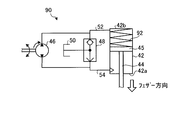
- FIG. 6 is a block diagram showing a schematic configuration of another embodiment of the cylinder driving device. 6 includes a cylinder 42, a connecting member 44, a piston 45, a bidirectional hydraulic pump 46, a check valve 48, a tank 50, pipes 52 and 54, and a spring 92.
- the cylinder 42, the connecting member 44, the piston 45, the bidirectional hydraulic pump 46, the check valve 48, the tank 50, and the pipes 52 and 54 are the same as the respective parts of the cylinder drive device 40 shown in FIG. It is the composition.
- the spring 92 is disposed between the piston 45 and the bottom surface 42 b of the cylinder 42.
- the spring 92 is an extrusion spring and pushes the piston 45 toward the top surface 42 a of the cylinder 42. That is, force is applied in the direction in which the moving blade 18 moves in the feather direction.
- the spring 92 always pushes the piston 45 toward the top surface 42a of the cylinder 42.
- the cylinder driving device 90 is configured as described above. During normal operation, the hydraulic oil is supplied to the cylinder 42 via the pipe 52 and / or the pipe 54 by the bidirectional hydraulic pump 46 as in the cylinder driving apparatus 40. The piston 45 is moved to move the moving blade 18 in the feather direction or the fine direction. The spring 92 is disposed between the piston 45 and the bottom surface 42 b of the cylinder 42.
- the cylinder drive device is useful for controlling the pitch angle of the rotor blades of a wind power generation system, and is particularly suitable for use in a wind power generation system that needs to appropriately control the pitch angle even during a power failure. .
Landscapes
- Engineering & Computer Science (AREA)
- Mechanical Engineering (AREA)
- General Engineering & Computer Science (AREA)
- Life Sciences & Earth Sciences (AREA)
- Sustainable Development (AREA)
- Sustainable Energy (AREA)
- Chemical & Material Sciences (AREA)
- Combustion & Propulsion (AREA)
- Physics & Mathematics (AREA)
- Fluid Mechanics (AREA)
- Wind Motors (AREA)
Abstract
Description
ピストン45は、連結部材44のシリンダ42の内部に配置された側の端部に連結された、シリンダ42の筒型形状の内壁と略同一形状の筒板部材である。このピストン45により、シリンダ42の内部の空間は、シリンダ42の頂面42a側と底面42b側とに分断される。ピストン45は、シリンダ42の底面42b側に接続された配管52から供給される作動油と、シリンダ42の頂面42a側に接続された配管54から供給される作動油との量の差、つまりシリンダ42の内部に供給される作動油の油圧の差により生じる力を受ける。ピストン45は、作動油から受ける力により、より圧力が低い方向にシリンダ42に沿って移動する。具体的には、ピストン45は、配管52から作動油が供給されたらシリンダ42の底面42bから離れる方向に移動し、配管54から作動油が供給されたらシリンダ42の底面42bに近づく方向に移動する。また、ピストン45と動翼18とは、連結部材44を介して連結されているため、ピストン45の往復運動は、連結部材44を介して動翼18に伝達され、動翼18がリンクの中心を基準として(つまり、動翼18の回動軸を中心に)回動される。動翼18が動翼18の回動軸を中心に回動することで、動翼18のピッチ角が変化する。具体的には、ピストン45が底面42bから離れる方向に移動すると、動翼18のピッチ角は、風を受け流す方向(以下「フェザー方向」という。)に変化し、ピストン45が底面42bに近づく方向に移動すると、動翼18のピッチ角は、風の力を寄り大きく受け止める方向、つまり、吹き付けられた風の力をより多く回転する力に変換する方向(以下「ファイン方向」という。)に変化する。
11 基礎
12 支柱
14 ナセル
16 ロータヘッド
18、230 動翼
20 増速機
22 発電機
24 風速計
26 風向計
28 避雷針
30 制御部
40、70、80、90、200 シリンダ駆動装置
42、202 シリンダ
44 連結部材
45、203 ピストン
46、204 双方向油圧ポンプ
48、206 チェック弁
50、208 タンク
52、54、210、212 配管
56、82、220 油圧調整機構
60、222 アキュムレータ
62、224 オンオフ弁
64、226 安全弁
66 オンオフ弁駆動用電源
68、72、92 ばね(スプリング)
84 切換弁
Claims (5)
- 動翼のピッチ角を調整するシリンダ駆動装置であって、
前記動翼と連結部材を介して連結されたピストンと、
内部に前記ピストンが配置され、外部から供給される作動油の油圧の圧力差により前記ピストンの端部を往復移動させ、前記ピストンを往復運動させるシリンダと、
前記シリンダの内部に配置され、前記ピストンを一方向に付勢する付勢部材と、
前記シリンダに接続され、前記付勢部材により付勢される方向とは反対側の方向に前記ピストンを付勢する作動油を前記シリンダに供給するアキュムレータと、
前記アキュムレータと前記シリンダとの間の流路の開閉を制御するオンオフ弁とを有することを特徴とするシリンダ駆動装置。 - 前記オンオフ弁は、停電発生時に前記アキュムレータと前記シリンダとの間の流路を開くことを特徴とする請求項1に記載のシリンダ駆動装置。
- 動翼のピッチ角を調整するシリンダ駆動装置であって、
前記動翼と連結されたピストンと、
内部に前記ピストンが配置され、外部から供給される作動油の油圧の圧力差により前記ピストンの端部を往復移動させ、前記ピストンを往復運動させるシリンダと、
前記シリンダに作動油を供給する作動油供給手段と、
前記ピストンを一方向に付勢するように、前記作動油供給手段から供給された作動油を前記シリンダに供給する第1配管と、
前記ピストンを前記一方向とは反対側の方向に付勢するように、前記作動油供給手段から供給された作動油を前記シリンダに供給する第2配管と、
前記シリンダに接続され、前記シリンダに接続された配管に作動油を供給するアキュムレータと、
前記アキュムレータと前記シリンダとの間の流路の開閉を制御するオンオフ弁と、
前記オンオフ弁と前記シリンダとの間に配置され、前記アキュムレータから供給された作動油を前記第1配管に供給する経路と、前記アキュムレータから供給された作動油を前記第2配管に供給する経路とを切換可能な切換手段とを有することを特徴とするシリンダ駆動装置。 - 前記作動油供給手段は、停電発生時に停止し、
前記オンオフ弁は、停電発生時に前記アキュムレータと前記シリンダとの間の流路を開き、
前記切換手段は、停電発生時に起動することを特徴とする請求項3に記載のシリンダ駆動装置。 - 動翼のピッチ角を調整するシリンダ駆動装置であって、
前記動翼と連結されたピストンと、
内部に前記ピストンが配置され、外部から供給される作動油の油圧の圧力差により前記ピストンの端部を往復移動させ、前記ピストンを往復運動させるシリンダと、
前記シリンダに作動油を供給する作動油供給手段と、
前記ピストンを一方向に付勢するように、前記作動油供給手段から供給された作動油を前記シリンダに供給する第1配管と、
前記ピストンを前記一方向とは反対側の方向に付勢するように、前記作動油供給手段から供給された作動油を前記シリンダに供給する第2配管と、
前記シリンダの内部に配置され、前記動翼が風を受け流す方向に移動するように前記ピストンを移動させる方向に付勢する付勢部材と、を有することを特徴とするシリンダ駆動装置。
Priority Applications (7)
| Application Number | Priority Date | Filing Date | Title |
|---|---|---|---|
| EP09838849A EP2381096A1 (en) | 2009-01-22 | 2009-11-10 | Cylinder drive device |
| CN2009801314041A CN102119272B (zh) | 2009-01-22 | 2009-11-10 | 工作缸驱动装置 |
| AU2009338345A AU2009338345B2 (en) | 2009-01-22 | 2009-11-10 | Cylinder drive device |
| CA2732985A CA2732985C (en) | 2009-01-22 | 2009-11-10 | Cylinder driving device |
| BRPI0917101A BRPI0917101A2 (pt) | 2009-01-22 | 2009-11-10 | dispositivo de acionamento de cilindro |
| US13/059,072 US20110142640A1 (en) | 2009-01-22 | 2009-11-10 | Cylinder driving device |
| KR1020117003186A KR101248676B1 (ko) | 2009-01-22 | 2009-11-10 | 실린더 구동 장치 |
Applications Claiming Priority (2)
| Application Number | Priority Date | Filing Date | Title |
|---|---|---|---|
| JP2009-012280 | 2009-01-22 | ||
| JP2009012280A JP5438979B2 (ja) | 2009-01-22 | 2009-01-22 | シリンダ駆動装置 |
Publications (1)
| Publication Number | Publication Date |
|---|---|
| WO2010084659A1 true WO2010084659A1 (ja) | 2010-07-29 |
Family
ID=42355728
Family Applications (1)
| Application Number | Title | Priority Date | Filing Date |
|---|---|---|---|
| PCT/JP2009/069127 Ceased WO2010084659A1 (ja) | 2009-01-22 | 2009-11-10 | シリンダ駆動装置 |
Country Status (9)
| Country | Link |
|---|---|
| US (1) | US20110142640A1 (ja) |
| EP (1) | EP2381096A1 (ja) |
| JP (1) | JP5438979B2 (ja) |
| KR (1) | KR101248676B1 (ja) |
| CN (1) | CN102119272B (ja) |
| AU (1) | AU2009338345B2 (ja) |
| BR (1) | BRPI0917101A2 (ja) |
| CA (1) | CA2732985C (ja) |
| WO (1) | WO2010084659A1 (ja) |
Families Citing this family (12)
| Publication number | Priority date | Publication date | Assignee | Title |
|---|---|---|---|---|
| AU2010201622B1 (en) * | 2010-02-22 | 2011-07-21 | Mitsubishi Heavy Industries, Ltd. | Wind turbine generator and soundness diagnosis method thereof |
| CN103827478A (zh) * | 2011-08-04 | 2014-05-28 | 保罗·勃特略 | 风力利用平台上的风能发电机 |
| BRPI1104101B1 (pt) * | 2011-08-04 | 2013-04-30 | gerador de energia eàlica em plataforma na base da captaÇço dos ventos. | |
| US9695802B2 (en) | 2012-05-22 | 2017-07-04 | United Technologies Corporation | Wind turbine load mitigation |
| CN102808730B (zh) * | 2012-08-23 | 2016-03-30 | 上海汇益控制系统股份有限公司 | 大功率风力发电液压变桨系统 |
| KR200482643Y1 (ko) * | 2012-11-08 | 2017-02-16 | 대우조선해양 주식회사 | 풍력 발전 장치용 피칭장치의 메뉴얼 구동 시스템 |
| JP6746511B2 (ja) * | 2017-01-31 | 2020-08-26 | 株式会社東芝 | 蒸気タービン弁駆動装置 |
| CN113074087B (zh) * | 2021-04-12 | 2022-06-03 | 南通理工学院 | 一种用于新能源混合动力船舶的风力发电装置 |
| CN113062831B (zh) * | 2021-04-12 | 2022-04-19 | 南通理工学院 | 一种新能源混合动力船舶用发电装置 |
| KR102361767B1 (ko) * | 2021-11-30 | 2022-02-14 | (주)삼원밀레니어 | 유압 구동 피치제어기를 이용한 풍력발전용 장치 |
| KR102556369B1 (ko) * | 2021-12-15 | 2023-07-18 | 주식회사 금풍 | 전원 비인가형 피치복원 구조를 갖는 풍력발전기 |
| CN117021154B (zh) * | 2023-07-25 | 2026-04-21 | 浙江工业大学 | 一种应用于外骨骼机器人的液压缸阀一体式关节作动器 |
Citations (2)
| Publication number | Priority date | Publication date | Assignee | Title |
|---|---|---|---|---|
| JP2002276535A (ja) | 2001-03-21 | 2002-09-25 | Kayaba Ind Co Ltd | 可変翼機構 |
| JP2007238599A (ja) | 2006-02-10 | 2007-09-20 | Ube Ind Ltd | オキセタン環含有化合物の保存方法及び当該方法によって得られる組成物 |
Family Cites Families (19)
| Publication number | Priority date | Publication date | Assignee | Title |
|---|---|---|---|---|
| GB1050088A (ja) * | ||||
| SE321160B (ja) * | 1969-06-06 | 1970-02-23 | B Almqvist | |
| AU5724480A (en) * | 1979-04-23 | 1980-10-30 | Maschinenfabrik Augsburg-Nurnberg Aktiengesellschaft | Wind motor vane pitch control |
| US4348155A (en) * | 1980-03-17 | 1982-09-07 | United Technologies Corporation | Wind turbine blade pitch control system |
| JPS59212576A (ja) * | 1983-05-17 | 1984-12-01 | Sumitomo Precision Prod Co Ltd | プロペラ型風車発電機の制御方法 |
| JPH0473411A (ja) * | 1990-07-13 | 1992-03-09 | Sumitomo Heavy Ind Ltd | 空気アクチュエータのフェイルセーフ装置 |
| JPH05149237A (ja) * | 1991-11-26 | 1993-06-15 | Mitsubishi Heavy Ind Ltd | 風車のピツチ可変装置 |
| JP3700076B2 (ja) * | 1999-01-25 | 2005-09-28 | 株式会社日立製作所 | 油圧サーボ制御装置および油圧サーボ制御システム |
| US6261062B1 (en) * | 2000-01-17 | 2001-07-17 | Brunswick Corporation | Actuation system for a controllable pitch propeller |
| JP2002364516A (ja) * | 2001-06-04 | 2002-12-18 | Kayaba Ind Co Ltd | 風車の可変翼装置 |
| JP4233400B2 (ja) * | 2003-07-04 | 2009-03-04 | ナブテスコ株式会社 | 風車羽根のピッチ角駆動装置 |
| JP2005030265A (ja) * | 2003-07-10 | 2005-02-03 | Ts Corporation | 風車ブレードのピッチ角制御装置 |
| CN1752439A (zh) * | 2005-10-31 | 2006-03-29 | 朱汪逸 | 风力发电机液压变桨装置 |
| ES2279725B1 (es) * | 2006-02-09 | 2008-07-16 | Hydra-Power, S.L. | Dispositivo para el control de las palas de un aerogenerador. |
| JP4773850B2 (ja) * | 2006-03-08 | 2011-09-14 | 三菱重工業株式会社 | 風力発電システム、及び風力発電システムの非常用電力供給方法 |
| ES2327695B1 (es) * | 2006-10-11 | 2010-09-06 | GAMESA INNOVATION & TECHNOLOGY, S.L. | Sistema de giro de una pala de aerogenerador. |
| CN201092931Y (zh) * | 2007-06-04 | 2008-07-30 | 无锡宝南机器制造有限公司 | 风力发电机的独立液压变桨机构 |
| JP4100520B1 (ja) * | 2007-12-28 | 2008-06-11 | 川崎重工業株式会社 | アップウインド型風車及びその退避運転方法 |
| CN101324220B (zh) * | 2008-07-17 | 2011-12-07 | 无锡宝南机器制造有限公司 | 风力发电机的变桨机构 |
-
2009
- 2009-01-22 JP JP2009012280A patent/JP5438979B2/ja not_active Expired - Fee Related
- 2009-11-10 CA CA2732985A patent/CA2732985C/en not_active Expired - Fee Related
- 2009-11-10 WO PCT/JP2009/069127 patent/WO2010084659A1/ja not_active Ceased
- 2009-11-10 CN CN2009801314041A patent/CN102119272B/zh not_active Expired - Fee Related
- 2009-11-10 US US13/059,072 patent/US20110142640A1/en not_active Abandoned
- 2009-11-10 EP EP09838849A patent/EP2381096A1/en not_active Withdrawn
- 2009-11-10 KR KR1020117003186A patent/KR101248676B1/ko not_active Expired - Fee Related
- 2009-11-10 AU AU2009338345A patent/AU2009338345B2/en not_active Expired - Fee Related
- 2009-11-10 BR BRPI0917101A patent/BRPI0917101A2/pt not_active IP Right Cessation
Patent Citations (2)
| Publication number | Priority date | Publication date | Assignee | Title |
|---|---|---|---|---|
| JP2002276535A (ja) | 2001-03-21 | 2002-09-25 | Kayaba Ind Co Ltd | 可変翼機構 |
| JP2007238599A (ja) | 2006-02-10 | 2007-09-20 | Ube Ind Ltd | オキセタン環含有化合物の保存方法及び当該方法によって得られる組成物 |
Also Published As
| Publication number | Publication date |
|---|---|
| CN102119272A (zh) | 2011-07-06 |
| AU2009338345A1 (en) | 2010-07-29 |
| US20110142640A1 (en) | 2011-06-16 |
| CN102119272B (zh) | 2013-01-09 |
| CA2732985A1 (en) | 2010-07-29 |
| CA2732985C (en) | 2013-03-26 |
| JP5438979B2 (ja) | 2014-03-12 |
| KR20110030676A (ko) | 2011-03-23 |
| KR101248676B1 (ko) | 2013-04-01 |
| BRPI0917101A2 (pt) | 2015-11-03 |
| AU2009338345B2 (en) | 2013-03-21 |
| JP2010168996A (ja) | 2010-08-05 |
| EP2381096A1 (en) | 2011-10-26 |
Similar Documents
| Publication | Publication Date | Title |
|---|---|---|
| JP5438979B2 (ja) | シリンダ駆動装置 | |
| CN101583793B (zh) | 风轮机叶片桨距系统 | |
| US8736096B2 (en) | Water flow electricity generating device | |
| WO2012073279A1 (en) | Wind turbine generator system and operation control method thereof | |
| CN101981313B (zh) | 风力发电装置 | |
| KR20130083392A (ko) | 재생 에너지형 발전 장치 및 그 제어 방법 | |
| EP2791501B1 (en) | A yawing system comprising a preload mechanism | |
| KR20130047699A (ko) | 유압 트랜스미션을 가지는 풍력 터빈과 같은 재생가능 에너지 추출 장치 | |
| US9890767B2 (en) | Wind energy system with a pitch adjustment system | |
| US20120025531A1 (en) | Energy generation using intermediary buffering | |
| JP2002276535A (ja) | 可変翼機構 | |
| AU2007213622A1 (en) | Device for controlling the blades of a wind turbine | |
| CN109667714A (zh) | 液体静压变桨系统及其控制方法 | |
| US11542918B2 (en) | Method of controlling a blade pitch angle of a wind turbine by use of a hydraulic system | |
| WO2014194463A1 (zh) | 液压马达驱动装置 | |
| JP4233400B2 (ja) | 風車羽根のピッチ角駆動装置 | |
| CN103061978A (zh) | 桨距调节装置 | |
| JP2007107410A (ja) | 風力発電装置 | |
| JP2012193642A (ja) | 風力発電装置 | |
| KR20130109413A (ko) | 유압식 풍력 발전 장치 및 그 방법 | |
| JP2007107409A (ja) | 風力発電装置 | |
| JP2002364516A (ja) | 風車の可変翼装置 | |
| WO2024236269A1 (en) | Wind turbine | |
| JP2005030265A (ja) | 風車ブレードのピッチ角制御装置 | |
| JP2018109391A (ja) | 液圧装置および風力発電装置 |
Legal Events
| Date | Code | Title | Description |
|---|---|---|---|
| WWE | Wipo information: entry into national phase |
Ref document number: 200980131404.1 Country of ref document: CN |
|
| 121 | Ep: the epo has been informed by wipo that ep was designated in this application |
Ref document number: 09838849 Country of ref document: EP Kind code of ref document: A1 |
|
| WWE | Wipo information: entry into national phase |
Ref document number: 2009338345 Country of ref document: AU |
|
| ENP | Entry into the national phase |
Ref document number: 2732985 Country of ref document: CA |
|
| ENP | Entry into the national phase |
Ref document number: 20117003186 Country of ref document: KR Kind code of ref document: A |
|
| WWE | Wipo information: entry into national phase |
Ref document number: 13059072 Country of ref document: US |
|
| WWE | Wipo information: entry into national phase |
Ref document number: 1154/CHENP/2011 Country of ref document: IN |
|
| WWE | Wipo information: entry into national phase |
Ref document number: 2009838849 Country of ref document: EP |
|
| ENP | Entry into the national phase |
Ref document number: 2009338345 Country of ref document: AU Date of ref document: 20091110 Kind code of ref document: A |
|
| NENP | Non-entry into the national phase |
Ref country code: DE |
|
| ENP | Entry into the national phase |
Ref document number: PI0917101 Country of ref document: BR Kind code of ref document: A2 Effective date: 20110224 |