WO2010087097A1 - 容器のガス置換方法及びその装置 - Google Patents
容器のガス置換方法及びその装置 Download PDFInfo
- Publication number
- WO2010087097A1 WO2010087097A1 PCT/JP2009/071576 JP2009071576W WO2010087097A1 WO 2010087097 A1 WO2010087097 A1 WO 2010087097A1 JP 2009071576 W JP2009071576 W JP 2009071576W WO 2010087097 A1 WO2010087097 A1 WO 2010087097A1
- Authority
- WO
- WIPO (PCT)
- Prior art keywords
- bottle
- cap
- nozzle
- inert gas
- gas
- Prior art date
- Legal status (The legal status is an assumption and is not a legal conclusion. Google has not performed a legal analysis and makes no representation as to the accuracy of the status listed.)
- Ceased
Links
Images



Classifications
-
- B—PERFORMING OPERATIONS; TRANSPORTING
- B67—OPENING, CLOSING OR CLEANING BOTTLES, JARS OR SIMILAR CONTAINERS; LIQUID HANDLING
- B67C—CLEANING, FILLING WITH LIQUIDS OR SEMILIQUIDS, OR EMPTYING, OF BOTTLES, JARS, CANS, CASKS, BARRELS, OR SIMILAR CONTAINERS, NOT OTHERWISE PROVIDED FOR; FUNNELS
- B67C3/00—Bottling liquids or semiliquids; Filling jars or cans with liquids or semiliquids using bottling or like apparatus; Filling casks or barrels with liquids or semiliquids
- B67C3/02—Bottling liquids or semiliquids; Filling jars or cans with liquids or semiliquids using bottling or like apparatus
- B67C3/22—Details
- B67C3/222—Head-space air removing devices, e.g. by inducing foam
-
- B—PERFORMING OPERATIONS; TRANSPORTING
- B65—CONVEYING; PACKING; STORING; HANDLING THIN OR FILAMENTARY MATERIAL
- B65B—MACHINES, APPARATUS OR DEVICES FOR, OR METHODS OF, PACKAGING ARTICLES OR MATERIALS; UNPACKING
- B65B31/00—Packaging articles or materials under special atmospheric or gaseous conditions; Adding propellants to aerosol containers
- B65B31/04—Evacuating, pressurising or gasifying filled containers or wrappers by means of nozzles through which air or other gas, e.g. an inert gas, is withdrawn or supplied
- B65B31/046—Evacuating, pressurising or gasifying filled containers or wrappers by means of nozzles through which air or other gas, e.g. an inert gas, is withdrawn or supplied the nozzles co-operating, or being combined, with a device for opening or closing the container or wrapper
Definitions
- the present invention provides a method for replacing a gas in a container and its apparatus, and in particular, obtains a high replacement effect with a smaller amount of inert gas used without spilling bubbles or content liquid when replacing the gas in the head space of the container.
- the present invention relates to a gas replacement method and apparatus for a container capable of performing the above.
- the contents may be oxidized by oxygen in the air, and the sensory components such as taste and flavor may be altered. Therefore, after filling the PET bottle, the head space at the bottle mouth must be replaced with an inert gas such as nitrogen before the sealing process with the cap.
- the bottle filled with the contents is transported by the turret, while the cap is also transported by the turret in a form held by the capper head, and is tightened by the capper head when the axis of the bottle coincides with the axis of the cap. And sealed.
- gas blowing nozzles caps nozzles, bottle nozzles both inside the cap and in the bottle mouth headspace until just before the cap is fitted into the bottle mouth. It is preferable to pour an inert gas.
- the bottle comes close to the cap, there is a limit to the relative position where the cap nozzle can come close to the cap.
- the capper head comes close to the bottle, there is a limit to the relative position where the bottle nozzle can come close to the bottle. That is, there is a nozzle non-proximity zone in which the “gas blowing nozzle” cannot approach the cap and the bottle.
- the bottle mouth head space is replaced with an inert gas from above the container mouth by the injection nozzle and the louver, and the subsequent cap fitting is performed.
- the entire process from the pre-capping process to the capping process is performed by a louver.
- the inert gas is allowed to flow from the lateral direction, and the inflow of air into the bottle mouth and the cap is prevented in all processes from the pre-capping process to the capping process due to the curtain effect of the inert gas.
- the atmosphere in the nozzle non-proximity zone itself is replaced with an inert gas after all.
- An object of the present invention is to provide a gas replacement method for a container and an apparatus for the same, which can obtain a high replacement effect with the amount of gas used.
- the container gas replacement method according to claim 1, wherein the head space of the container is replaced with an inert gas before the sealing step with a cap.
- the "first nozzle nozzle” continues to flow inert gas into the cap from below the cap until it does not interfere with the bottle, and then until just before fitting with the bottle.
- the nozzle for the second cap "avoids interference between the bottle and the capper head and keeps flowing the inert gas into the cap from an obliquely lower position close to the cap,
- the inert gas continues to flow into the bottle mouth head space from above the bottle until the “first bottle nozzle” does not interfere with the capper head, and then the cap “Nozzle for the second bottle” keeps flowing the inert gas into the bottle mouth portion head space from the upper side in the vicinity of the bottle mouth portion while avoiding the interference between the bottle and the capper head until just before fitting with the bottle mouth portion. It is characterized by.
- the conventional gas nozzle In the gas replacement method of the container, in addition to the cap and the bottle being transported by the turret, the conventional gas nozzle cannot be close to the inside of the cap or the bottle mouth head space. It is comprised so that an inert gas can be poured into the inside of a cap and a bottle mouth part head space until just before fitting to a bottle mouth part. That is, until the cap and the bottle are transported by each turret and enter the conventional nozzle non-proximity zone, the “first cap nozzle” and the “first bottle nozzle” are respectively from below and above from the inside of the cap and the bottle. Pour inert gas into the mouth headspace.
- each gas nozzle can be close to the inside of the cap or the bottle mouth head space, so the bottle mouth head with a smaller amount of inert gas than before.
- the space replacement rate can be increased.
- each nozzle can be close to the inside of the cap and the bottle mouth until just before the cap is fitted to the bottle mouth, the flow rate and flow rate of the inert gas injected from the nozzle are also higher than before. It becomes possible to make it small, and it becomes possible to prevent suitably the contamination of the line by the bubble and the spill of the content liquid.
- the target point of each nozzle is adjusted so as to follow the movement of the cap or bottle mouth part relatively and to be the center of the cap interior or the bottle mouth head space. Or reflow of the air to a bottle mouth part is prevented suitably.
- the target point of the second cap nozzle is always near the center inside the cap until just before the cap is fitted to the bottle.
- the air inside the cap is suitably expelled from the nozzle non-proximity zone during the cap sealing process, and the reflow of air is preferably performed. Can be prevented.
- the target point of the second bottle nozzle is always near the center of the bottle mouth head space until just before the bottle is fitted to the cap. It was.
- the air in the bottle mouth head space is suitably expelled from the nozzle non-proximity zone during the cap sealing process, and the air is re-exposed. Inflow can be suitably prevented.
- the inert gas replacement apparatus replaces the inside of the cap and the bottle mouth head space with an inert gas before the sealing step with the cap, “Nozzle for first cap” for injecting inert gas into the cap from the lower side of the cap to a range where it does not interfere with the bottle, and the bottle and capper until just before mating with the bottle.
- Nozzle for second cap '' that flows in an inert gas from obliquely below and close to the cap while avoiding head interference
- a "second bottle nozzle" is provided that flows in an inert gas into the bottle mouth head space obliquely from above and close to the bottle mouth while avoiding interference between the bottle and the capper head. .
- the gas replacement method of the container according to claim 1 can be suitably performed.
- the second cap nozzle is configured so that a target point with respect to the inside of the cap is constant.
- the container gas replacement method according to the second aspect can be suitably implemented.
- the second bottle nozzle is configured such that a target point with respect to the bottle mouth portion is constant.
- the gas replacement method for a container according to claim 3 can be suitably implemented.
- each cap nozzle and the bottle nozzle for injecting the inert gas are close to the cap or the bottle mouth portion, respectively.
- An inert gas can be poured into each interior.
- the cap nozzle and the bottle nozzle are configured so as to relatively follow the moving direction of the cap or the bottle, respectively, and the target point thereof is the center of the cap or the center of the bottle mouth. Accordingly, it is possible to promote gas replacement with respect to the inside of the cap and the bottle mouth head space with a small amount of inert gas, and to appropriately prevent air re-inflow.
- the nozzle can be close to the cap or the bottle mouth until just before the cap and the bottle mouth are fitted, the flow rate and flow rate of the gas injected from each nozzle can be small, and as a result, the gas It is possible to suitably prevent contamination of the line due to bubbles or spilled contents of the liquid during replacement.
- the above-described container gas replacement method can be suitably implemented.
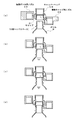
- FIG. 2 is a partial cross-sectional view along Ax-Ax in FIG. 1. It is explanatory drawing which shows the nozzle for side bottles which concerns on this invention.
- FIG. 2 is a partial cross-sectional view of Bx-Bx in FIG. 1. It is explanatory drawing which shows the nozzle for side caps which concerns on this invention.
- FIG. 1 is a configuration explanatory view showing a gas replacement device 100 for a PET bottle according to the present invention.
- This PET bottle gas replacement device 100 is a bottle nozzle 10 as a “first bottle nozzle” for flowing nitrogen gas from above into the mouth head space of the bottle B to the extent that it does not interfere with the capper head CH (not shown).
- the side-side bottle nozzle 20 as a “first cap nozzle” for flowing nitrogen gas from below into the inside of the cap C to the extent that it does not interfere with the bottle B, and gas replacement by the cap nozzle 30
- Nitrogen gas is poured into the inside of the cap C obliquely from below until just before the rear cap C is fitted into the mouth of the bottle B. It is configured by including a lateral side cap for the nozzle 40 as a "second nozzle cap.”
- the side bottle nozzle 20 and the side cap nozzle 40 are nitrogen until just before the cap C is fitted into the mouth of the bottle B.
- the gas can be poured into the mouth of the bottle B or the inside of the cap C, respectively.
- the bottle nozzle 10 has a plurality of gas injection holes whose injection directions are parallel to the central axis of the bottle so that nitrogen gas can continuously flow into the mouth head space of the bottle B from above. It is arranged along the moving direction of the bottle B on the turret BT. However, the dispositionable range is up to a range that does not interfere with the capper head CH (not shown). About the range exceeding it, the nozzle 20 for side bottles continuously pours nitrogen gas into the opening part head space of the bottle B from diagonally upward. At that time, as shown in FIG. 2, the center of the head space of the bottle B while the side bottle nozzle 20 relatively follows the moving direction of the bottle B until just before the cap C is fitted to the mouth of the bottle B. Nitrogen gas is continuously poured into the vicinity.
- the cap nozzle 30 has a plurality of gas injection holes on the cap turret CT whose injection directions are parallel to the cap central axis so that nitrogen gas can continuously flow into the cap C from below.
- the cap C is disposed along the moving direction.
- the disposition range is within a range not interfering with the bottle B.
- the nozzle 40 for side caps continuously pours nitrogen gas into the inside of the cap C from diagonally downward. At that time, as shown in FIG. 2, until the cap C is fitted into the mouth of the bottle B, the side cap nozzle 40 relatively follows the moving direction of the cap C, while the nitrogen in the vicinity of the inner center thereof. Flow gas continuously.
- the entire head atmosphere of the bottle B is replaced by an inert gas including the range. And re-inflow of air into the cap C was prevented.
- nitrogen gas can be continuously flowed into the bottle mouth and the cap until just before the cap C and the bottle B are fitted. It becomes possible to obtain a high replacement effect in the mouth head space of the bottle B by the amount used.
- the side bottle nozzle 20 and the side cap nozzle 40 can be close to the cap and the bottle mouth until just before the cap C and the bottle B are fitted, the gas injected from each nozzle. As a result, it is possible to suitably prevent the contamination of the line due to bubbles and spilled contents in the gas replacement.
- FIG. 3 is a partial cross-sectional view of Ax-Ax of FIG.
- the bottle nozzle 10 continuously flows nitrogen gas into the mouth head space of the bottle B from above. Further, a step is provided at the tip of the bottle nozzle 10, whereby the bottle nozzle 10 and the side bottle nozzle 20 can overlap. Due to the overlap, the nitrogen gas is allowed to flow into the mouth of the bottle B without a break between the bottle nozzle 10 and the side bottle nozzle 20. As a result, the air expelled from the bottle mouth head space cannot re-enter the head space. Further, because of this step, it is possible to avoid interference with the capper head CH, so that it is possible to lengthen the “continuous flow of nitrogen gas from above” time.
- the side bottle nozzle 20 then continuously flows nitrogen gas into the bottle B head space from obliquely above. Thereby, by flowing nitrogen gas from a direction different from the nozzle 10 for the bottle, the replacement rate in the head space of the bottle B is further improved, while reflow of air is suitably prevented.
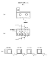
- FIG. 4 is an explanatory view showing the side bottle nozzle 20.
- 4A is a plan view
- FIG. 4B is a front view
- FIG. 4C is a cross-sectional view.
- the side bottle nozzle 20 flows nitrogen gas into the mouth of the bottle B until just before the cap C is fitted into the mouth of the bottle B.
- the front surface is curved inward so as to be as close to the mouth of the bottle B as possible.
- the side bottle nozzle 20 includes four gas injection holes 21 through which nitrogen gas flows out.
- the injection angles are all 45 ° downward with respect to the horizontal direction.
- the clearance between the side bottle nozzle 20 and the cap head CH is preferably 3 mm for safety.
- FIG. 5 is a partial cross-sectional view of Bx-Bx in FIG.
- the cap nozzle 30 continuously flows nitrogen gas into the cap C being conveyed from below. Further, the injection surface for injecting the nitrogen gas of the cap nozzle 30 changes from a flat surface to a tapered surface corresponding to the conveyance (track) of the cap C. Further, the tip of the cap nozzle 30 and the rear portion of the side cap nozzle 40 are arranged so that the nitrogen gas flows between the cap nozzle 30 and the side cap nozzle 40 without interruption. It overlaps.
- the side cap nozzle 40 continuously flows nitrogen gas into the cap C from obliquely below. Further, as will be described later, the side cap nozzle 40 is provided with a step at the tip so as to avoid interference with the capper head CH, and the step surface is in the moving direction of the capper head CH. A corresponding tapered surface is formed. As a result, the side cap nozzle 40 can be introduced as close to the cap C as possible and flow nitrogen gas from a direction different from the cap nozzle 30. Thereby, while the replacement rate inside the cap C is further improved, the re-inflow of air is suitably prevented.
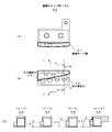
- FIG. 6 is an explanatory view showing the side cap nozzle 40.
- 6A is a plan view
- FIG. 6B is a front view
- FIG. 6C is a cross-sectional view.
- the side cap nozzle 40 is located as close as possible to the inside of the cap C as close as possible to the cap C until the cap C is fitted into the mouth of the bottle B after gas replacement by the cap nozzle 30. Pour nitrogen gas into the tube. Further, a stepped taper surface 41 is provided at the tip so as to be as close to the cap C as possible.
- the side cap nozzle 40 includes four gas injection holes 42, 43, 44, 45 through which nitrogen gas flows out. Further, as shown in FIG.
- the injection angle is such that the side cap nozzle 40 relatively follows the moving direction of the cap head CH (cap C) and flows nitrogen gas into the cap C. In order to be able to do so, they are 45 °, 30 °, 15 ° and 0 ° upward with respect to the horizontal direction.
- the clearance between the side cap nozzle 40 and the cap head CH is preferably 3 mm for safety.
- nitrogen gas is used as the inert gas.
- the present invention is not limited to this, and carbon dioxide gas, helium, or a mixed gas thereof may be used.
- PET bottles are used as containers.
- the present invention is not limited to this, and the present invention can also be applied to metal cans and glass bottles sealed with caps.
- the container gas replacement method and apparatus of the present invention can be applied to a gas replacement apparatus that replaces the air remaining in the head space of the container with an inert gas.
Landscapes
- Vacuum Packaging (AREA)
- Filling Of Jars Or Cans And Processes For Cleaning And Sealing Jars (AREA)
Abstract
本発明の課題は、容器のヘッドスペース内をガス置換する際に泡や内容液を吹きこぼすことなく、より少ない不活性ガスの使用量で高い置換効果を得ることが出来る容器のガス置換方法及びその装置を提供することである。本発明は、搬送されてくるボトル(B)に対し、キャッパーヘッド(CH)と干渉しない範囲に配設されたボトル用ノズル(10)によって、ボトル(B)の口部に上方から窒素ガスを流し込み、ボトル(B)及びキャッパーヘッド(CH)の干渉を回避して配設された横側ボトル用ノズル(20)によって、キャップ(C)と嵌合する直前までボトル(B)の口部に斜め上方から窒素ガスを流し込む一方、搬送されてくるキャップ(C)に対し、ボトル(B)と干渉しない範囲に配設されたキャップ用ノズル(30)によって、キャップ(C)の内部に下方から窒素ガスを流し込み、ボトル(B)及びキャッパーヘッド(CH)の干渉を回避して配設された横側キャップ用ノズル(40)によって、ボトル(B)と嵌合する直前までキャップ(C)の内部に斜め下方から窒素ガスを流し込むことを特徴とする。
Description
本発明は、容器のガス置換方法及びその装置、特に容器のヘッドスペース内をガス置換する際に泡や内容液を吹きこぼすことなく、より少ない不活性ガスの使用量で高い置換効果を得ることが出来る容器のガス置換方法及びその装置に関する。
ボトル口部のヘッドスペースに空気が多量に残存していると、空気中の酸素によって内容物が酸化され、味・風味等の官能成分を変質させてしまう虞がある。そのため、PETボトルに内容物を充填した後は、キャップによる密封工程の前にボトル口部のヘッドスペースを窒素等の不活性ガスで置換しなければならない。
内容物を充填されたボトルは、ターレットによって搬送され、一方、キャップはキャッパーヘッドに把持された形態で同じくターレットによって搬送され、ボトルの軸芯とキャップの軸芯が一致するところでキャッパーヘッドによって巻締められ密封される。従って、不活性ガスによる置換率の観点から、キャップがボトル口部に嵌合する直前まで、キャップ内部およびボトル口部ヘッドスペースの双方に、「ガス吹き出しノズル」(キャップ用ノズル,ボトル用ノズル)によって不活性ガスを流し込むことが好ましい。しかし、実際は、ボトルがキャップに近接して来るために、キャップ用ノズルがキャップに近接することが出来る相対位置には限界が存在する。他方、ボトル用ノズルについても同様に、キャッパーヘッドがボトルに近接して来るために、ボトル用ノズルがボトルに近接することが出来る相対位置には限界が存在する。つまり、「ガス吹き出しノズル」がキャップ及びボトルに近接することが出来ないノズル非近接ゾーンが存在する。このノズル非近接ゾーンのために、不活性ガスで置換されたキャップ内部およびボトル口部ヘッドスペースに空気が再び流入し、キャップ内部およびボトル口部ヘッドスペースにおける不活性ガスによる置換率を低下させていた。
ところで、ボトル口部のヘッドスペースにおける高い置換率を得るために、キャッピング前工程においてはボトル口部ヘッドスペースを容器口部の上方から噴射ノズルとルーバーにより不活性ガスで置換し、以降のキャップ嵌合までの間はボトル口部の横方向からルーバーにより不活性ガスを流し続け、他方、キャップ内面に対して、キャッピング前工程においては下方から不活性ガスで置換を行い、以降のボトル口部との嵌合までの間は上記横方向のルーバーによって不活性ガスを流し続け、「キャップとボトル口部の嵌合工程」における空気の巻き込み現象を防止した容器の不活性ガス置換方法及びその装置が知られている(特許文献1を参照。)。
内容物を充填されたボトルは、ターレットによって搬送され、一方、キャップはキャッパーヘッドに把持された形態で同じくターレットによって搬送され、ボトルの軸芯とキャップの軸芯が一致するところでキャッパーヘッドによって巻締められ密封される。従って、不活性ガスによる置換率の観点から、キャップがボトル口部に嵌合する直前まで、キャップ内部およびボトル口部ヘッドスペースの双方に、「ガス吹き出しノズル」(キャップ用ノズル,ボトル用ノズル)によって不活性ガスを流し込むことが好ましい。しかし、実際は、ボトルがキャップに近接して来るために、キャップ用ノズルがキャップに近接することが出来る相対位置には限界が存在する。他方、ボトル用ノズルについても同様に、キャッパーヘッドがボトルに近接して来るために、ボトル用ノズルがボトルに近接することが出来る相対位置には限界が存在する。つまり、「ガス吹き出しノズル」がキャップ及びボトルに近接することが出来ないノズル非近接ゾーンが存在する。このノズル非近接ゾーンのために、不活性ガスで置換されたキャップ内部およびボトル口部ヘッドスペースに空気が再び流入し、キャップ内部およびボトル口部ヘッドスペースにおける不活性ガスによる置換率を低下させていた。
ところで、ボトル口部のヘッドスペースにおける高い置換率を得るために、キャッピング前工程においてはボトル口部ヘッドスペースを容器口部の上方から噴射ノズルとルーバーにより不活性ガスで置換し、以降のキャップ嵌合までの間はボトル口部の横方向からルーバーにより不活性ガスを流し続け、他方、キャップ内面に対して、キャッピング前工程においては下方から不活性ガスで置換を行い、以降のボトル口部との嵌合までの間は上記横方向のルーバーによって不活性ガスを流し続け、「キャップとボトル口部の嵌合工程」における空気の巻き込み現象を防止した容器の不活性ガス置換方法及びその装置が知られている(特許文献1を参照。)。
上記容器の不活性ガス置換方法及びその装置では、キャッピング前工程における各ノズルによる垂直下方または垂直上方からの不活性ガスの噴射に加え、キャッピング前工程からキャッピング工程に到る全工程においてはルーバーによって横方向から不活性ガスをそれぞれ流し続け、不活性ガスのカーテン効果によりキャッピング前工程からキャッピング工程に到る全工程においてボトル口部及びキャップ内部への空気再流入を防止するようにしている。
しかし、上記容器のガス置換方法及びその装置は、結局、ノズル非近接ゾーンの雰囲気自体を不活性ガスによって置換している。つまり、キャップ内部およびボトル口部ヘッドスペースを置換するために、不活性ガスによって置換する必要のないスペースまでをも不活性ガスによって置換していることになる。その結果、大量の不活性ガスが必要になるという問題点を有していた。
また、大量の不活性ガスを流すために流量、流速を大きくすると、ボトル口部から泡や内容物が飛散し、充填ラインを汚染するという問題があった。
そこで、本発明は、かかる従来技術の問題点に鑑みなされたものであって、その目的は、容器のヘッドスペース内をガス置換する際に泡や内容液を吹きこぼすことなく、より少ない不活性ガスの使用量で高い置換効果を得ることが出来る容器のガス置換方法及びその装置を提供することにある。
しかし、上記容器のガス置換方法及びその装置は、結局、ノズル非近接ゾーンの雰囲気自体を不活性ガスによって置換している。つまり、キャップ内部およびボトル口部ヘッドスペースを置換するために、不活性ガスによって置換する必要のないスペースまでをも不活性ガスによって置換していることになる。その結果、大量の不活性ガスが必要になるという問題点を有していた。
また、大量の不活性ガスを流すために流量、流速を大きくすると、ボトル口部から泡や内容物が飛散し、充填ラインを汚染するという問題があった。
そこで、本発明は、かかる従来技術の問題点に鑑みなされたものであって、その目的は、容器のヘッドスペース内をガス置換する際に泡や内容液を吹きこぼすことなく、より少ない不活性ガスの使用量で高い置換効果を得ることが出来る容器のガス置換方法及びその装置を提供することにある。
前記目的を達成するために請求項1に記載の容器のガス置換方法では、キャップによる密封工程前に容器のヘッドスペースを不活性ガスによって置換する方法において、
搬送されて来るキャップに対し、「第一キャップ用ノズル」が前記ボトルと干渉しない範囲まで前記キャップの下方から該キャップ内部へ不活性ガスを流し込み続け、次に前記ボトルと嵌合する直前まで「第二キャップ用ノズル」が前記ボトル及びキャッパーヘッドの干渉を回避しながら前記キャップに近接し斜め下方から該キャップ内部へ不活性ガスを流し込み続け、
他方、搬送されて来る前記ボトルに対し、「第一ボトル用ノズル」が前記キャッパーヘッドと干渉しない範囲まで前記ボトルの上方から該ボトル口部ヘッドスペースへ不活性ガスを流し込み続け、次に前記キャップと嵌合する直前まで「第二ボトル用ノズル」が前記ボトル及び前記キャッパーヘッドの干渉を回避しながら前記ボトル口部に近接し斜め上方から該ボトル口部ヘッドスペースへ不活性ガスを流し込み続けることを特徴とする。
上記容器のガス置換方法では、キャップ及びボトルがターレットによって搬送されて来る間に加え、従来のガスノズルがキャップ内部またはボトル口部ヘッドスペースに近接することが出来ない、いわゆるノズル非近接ゾーンからキャップがボトル口部に嵌合する直前まで、キャップ内部及びボトル口部ヘッドスペースへ不活性ガスを流し込むことが出来るように構成されている。つまり、キャップ及びボトルが各ターレットによって搬送されて上記従来のノズル非近接ゾーンに入るまでは、「第一キャップ用ノズル」及び「第一ボトル用ノズル」がそれぞれ下方および上方から、キャップ内部およびボトル口部ヘッドスペースに不活性ガスを流し込む。更に、キャップ及びボトルが上記従来のノズル非近接ゾーンに入り嵌合する直前までは、「第二キャップ用ノズル」及び「第二ボトル用ノズル」が、それぞれ斜め下方および斜め上方から、キャップ内部およびボトル口部ヘッドスペースへ不活性ガスを流し込む。これにより、キャッピング前工程からキャッピング工程に到る全工程において、各ガスノズルは、キャップ内部またはボトル口部ヘッドスペースに各々近接することが出来るため、従来よりも少ない不活性ガス量でボトル口部ヘッドスペースの置換率を高めることが可能となる。
また、キャップがボトル口部に嵌合する直前まで、各ノズルがキャップ内部およびボトル口部に各々近接することが出来るため、ノズルから噴射される不活性ガスの流速および流量についても従来に比べより小さくすることが可能となり、泡や内容液の吹きこぼれによるラインの汚染を好適に防止することが可能となる。
また、後述するように、各ノズルのターゲットポイントは、キャップ又はボトル口部の移動に相対的に追従して、キャップ内部中心またはボトル口部ヘッドスペース中心となるように調整されているため、キャップ又はボトル口部への空気の再流入を好適に防止する。
搬送されて来るキャップに対し、「第一キャップ用ノズル」が前記ボトルと干渉しない範囲まで前記キャップの下方から該キャップ内部へ不活性ガスを流し込み続け、次に前記ボトルと嵌合する直前まで「第二キャップ用ノズル」が前記ボトル及びキャッパーヘッドの干渉を回避しながら前記キャップに近接し斜め下方から該キャップ内部へ不活性ガスを流し込み続け、
他方、搬送されて来る前記ボトルに対し、「第一ボトル用ノズル」が前記キャッパーヘッドと干渉しない範囲まで前記ボトルの上方から該ボトル口部ヘッドスペースへ不活性ガスを流し込み続け、次に前記キャップと嵌合する直前まで「第二ボトル用ノズル」が前記ボトル及び前記キャッパーヘッドの干渉を回避しながら前記ボトル口部に近接し斜め上方から該ボトル口部ヘッドスペースへ不活性ガスを流し込み続けることを特徴とする。
上記容器のガス置換方法では、キャップ及びボトルがターレットによって搬送されて来る間に加え、従来のガスノズルがキャップ内部またはボトル口部ヘッドスペースに近接することが出来ない、いわゆるノズル非近接ゾーンからキャップがボトル口部に嵌合する直前まで、キャップ内部及びボトル口部ヘッドスペースへ不活性ガスを流し込むことが出来るように構成されている。つまり、キャップ及びボトルが各ターレットによって搬送されて上記従来のノズル非近接ゾーンに入るまでは、「第一キャップ用ノズル」及び「第一ボトル用ノズル」がそれぞれ下方および上方から、キャップ内部およびボトル口部ヘッドスペースに不活性ガスを流し込む。更に、キャップ及びボトルが上記従来のノズル非近接ゾーンに入り嵌合する直前までは、「第二キャップ用ノズル」及び「第二ボトル用ノズル」が、それぞれ斜め下方および斜め上方から、キャップ内部およびボトル口部ヘッドスペースへ不活性ガスを流し込む。これにより、キャッピング前工程からキャッピング工程に到る全工程において、各ガスノズルは、キャップ内部またはボトル口部ヘッドスペースに各々近接することが出来るため、従来よりも少ない不活性ガス量でボトル口部ヘッドスペースの置換率を高めることが可能となる。
また、キャップがボトル口部に嵌合する直前まで、各ノズルがキャップ内部およびボトル口部に各々近接することが出来るため、ノズルから噴射される不活性ガスの流速および流量についても従来に比べより小さくすることが可能となり、泡や内容液の吹きこぼれによるラインの汚染を好適に防止することが可能となる。
また、後述するように、各ノズルのターゲットポイントは、キャップ又はボトル口部の移動に相対的に追従して、キャップ内部中心またはボトル口部ヘッドスペース中心となるように調整されているため、キャップ又はボトル口部への空気の再流入を好適に防止する。
請求項2に記載の容器のガス置換方法では、前記第二キャップ用ノズルのターゲットポイントは、前記キャップが前記ボトルと嵌合する直前まで、常時、前記キャップ内部の中心近傍であることとした。
上記容器のガス置換方法では、第二キャップ用ノズルのターゲットポイントを上記位置とすることにより、上記ノズル非近接ゾーンからキャップ密封工程の間にキャップ内部の空気を好適に追い出し空気の再流入を好適に防止することが可能となる。
上記容器のガス置換方法では、第二キャップ用ノズルのターゲットポイントを上記位置とすることにより、上記ノズル非近接ゾーンからキャップ密封工程の間にキャップ内部の空気を好適に追い出し空気の再流入を好適に防止することが可能となる。
請求項3に記載の容器のガス置換方法では、前記第二ボトル用ノズルのターゲットポイントは、前記ボトルが前記キャップと嵌合する直前まで、常時、前記ボトル口部ヘッドスペースの中心近傍であることとした。
上記容器のガス置換方法では、第二ボトル用ノズルのターゲットポイントを上記位置とすることにより、上記ノズル非近接ゾーンからキャップ密封工程の間にボトル口部ヘッドスペースの空気を好適に追い出し空気の再流入を好適に防止することが可能となる。
上記容器のガス置換方法では、第二ボトル用ノズルのターゲットポイントを上記位置とすることにより、上記ノズル非近接ゾーンからキャップ密封工程の間にボトル口部ヘッドスペースの空気を好適に追い出し空気の再流入を好適に防止することが可能となる。
請求項4に記載の容器のガス置換装置では、キャップによる密封工程前にキャップ内部およびボトル口部ヘッドスペースを不活性ガスによって置換する不活性ガス置換装置であって、
搬送されて来るキャップに対し、前記ボトルと干渉しない範囲まで前記キャップの下方から該キャップ内部に不活性ガスを流し込む「第一キャップ用ノズル」と、前記ボトルと嵌合する直前まで前記ボトル及びキャッパーヘッドの干渉を回避しながら前記キャップに近接し斜め下方から不活性ガスを流し込む「第二キャップ用ノズル」と、
他方、搬送されて来るボトルに対し、前記キャッパーヘッドと干渉しない範囲まで前記ボトルの上方から該ボトル口部へ不活性ガスを流し込む「第一ボトル用ノズル」と、前記キャップと嵌合する直前まで前記ボトル及び前記キャッパーヘッドの干渉を回避しながら前記ボトル口部に近接し斜め上方から該ボトル口部ヘッドスペースへ不活性ガスを流し込む「第二ボトル用ノズル」とを備えたことを特徴とする。
上記容器のガス置換では、上記請求項1に記載の容器のガス置換方法を好適に実施することが出来る。
搬送されて来るキャップに対し、前記ボトルと干渉しない範囲まで前記キャップの下方から該キャップ内部に不活性ガスを流し込む「第一キャップ用ノズル」と、前記ボトルと嵌合する直前まで前記ボトル及びキャッパーヘッドの干渉を回避しながら前記キャップに近接し斜め下方から不活性ガスを流し込む「第二キャップ用ノズル」と、
他方、搬送されて来るボトルに対し、前記キャッパーヘッドと干渉しない範囲まで前記ボトルの上方から該ボトル口部へ不活性ガスを流し込む「第一ボトル用ノズル」と、前記キャップと嵌合する直前まで前記ボトル及び前記キャッパーヘッドの干渉を回避しながら前記ボトル口部に近接し斜め上方から該ボトル口部ヘッドスペースへ不活性ガスを流し込む「第二ボトル用ノズル」とを備えたことを特徴とする。
上記容器のガス置換では、上記請求項1に記載の容器のガス置換方法を好適に実施することが出来る。
請求項5に記載の容器のガス置換装置では、前記第二キャップ用ノズルは、前記キャップ内部に対するターゲットポイントが一定となるように構成されていることとした。
上記容器のガス置換装置では、上記請求項2に記載の容器のガス置換方法を好適に実施することが出来る。
上記容器のガス置換装置では、上記請求項2に記載の容器のガス置換方法を好適に実施することが出来る。
請求項6に記載の容器のガス置換装置では、前記第二ボトル用ノズルは、前記ボトル口部に対するターゲットポイントが一定となるように構成されていることとした。
上記容器のガス置換装置では、上記請求項3に記載の容器のガス置換方法を好適に実施することが出来る。
上記容器のガス置換装置では、上記請求項3に記載の容器のガス置換方法を好適に実施することが出来る。
本発明の容器のガス置換方法によれば、キャップとボトル口部が嵌合する直前まで、不活性ガスを噴射する各キャップ用ノズル及びボトル用ノズルが、キャップ又はボトル口部に各々近接して各内部に対し不活性ガスを流し込むことが出来るように構成されている。また、上記キャップ用ノズル及びボトル用ノズルはキャップ又はボトルの移動方向に相対的に各々追従して、そのターゲットポイントがキャップ内部中心またはボトル口部中心となるように各々構成されている。これにより、少ない不活性ガス量によってキャップ内部およびボトル口部ヘッドスペースに対するガス置換を促進すると共に、空気再流入を好適に防止することが可能となる。つまり、少ない不活性ガス量によってボトル口部ヘッドスペースにおけるガス置換率を向上させることが可能となる。更に、上記ノズルは、キャップとボトル口部が嵌合する直前までキャップ又はボトル口部に各々近接することが出来るため、各ノズルから噴射されるガスの流速および流量は小さくて済み、その結果ガス置換の際の泡や内容液の吹きこぼれによるラインの汚染を好適に防止することが可能となる。
また本発明の容器のガス置換装置によれば、上記容器のガス置換方法を好適に実施することが出来る。
また本発明の容器のガス置換装置によれば、上記容器のガス置換方法を好適に実施することが出来る。
10 ボトル用ノズル
20 横側ボトル用ノズル
21 ガス噴射穴
30 キャップ用ノズル
40 横側キャップ用ノズル
41 段差テーパ面
42,43,44,45 ガス噴射穴
100 PETボトル用ガス置換装置
20 横側ボトル用ノズル
21 ガス噴射穴
30 キャップ用ノズル
40 横側キャップ用ノズル
41 段差テーパ面
42,43,44,45 ガス噴射穴
100 PETボトル用ガス置換装置
以下、図に示す実施の形態により本発明をさらに詳細に説明する。
図1は、本発明のPETボトル用ガス置換装置100を示す構成説明図である。
このPETボトルガス置換装置100は、キャッパーヘッドCH(図示せず)に干渉しない範囲までボトルBの口部ヘッドスペースに対し上方から窒素ガスを流し込む「第一ボトル用ノズル」としてのボトル用ノズル10と、ボトル用ノズル10によるガス置換の後キャップCがボトルBの口部に嵌合する直前までボトルBの口部ヘッドスペースに対し斜め上方から窒素ガスを流し込む「第二ボトル用ノズル」としての横側ボトル用ノズル20と、ボトルBに干渉しない範囲までキャップCの内部に対し下方から窒素ガスを流し込む「第一キャップ用ノズル」としてのキャップ用ノズル30と、キャップ用ノズル30によるガス置換の後キャップCがボトルBの口部に嵌合する直前までキャップCの内部に対し斜め下方から窒素ガスを流し込む「第二キャップ用ノズル」としての横側キャップ用ノズル40とを具備して構成されている。なお、詳細については、図2から図4を参照しながら後述するが、上記横側ボトル用ノズル20および横側キャップ用ノズル40は、キャップCがボトルBの口部に嵌合する直前まで窒素ガスをボトルBの口部またはキャップCの内部に各々流し込むことが出来るように構成されている。
このPETボトルガス置換装置100は、キャッパーヘッドCH(図示せず)に干渉しない範囲までボトルBの口部ヘッドスペースに対し上方から窒素ガスを流し込む「第一ボトル用ノズル」としてのボトル用ノズル10と、ボトル用ノズル10によるガス置換の後キャップCがボトルBの口部に嵌合する直前までボトルBの口部ヘッドスペースに対し斜め上方から窒素ガスを流し込む「第二ボトル用ノズル」としての横側ボトル用ノズル20と、ボトルBに干渉しない範囲までキャップCの内部に対し下方から窒素ガスを流し込む「第一キャップ用ノズル」としてのキャップ用ノズル30と、キャップ用ノズル30によるガス置換の後キャップCがボトルBの口部に嵌合する直前までキャップCの内部に対し斜め下方から窒素ガスを流し込む「第二キャップ用ノズル」としての横側キャップ用ノズル40とを具備して構成されている。なお、詳細については、図2から図4を参照しながら後述するが、上記横側ボトル用ノズル20および横側キャップ用ノズル40は、キャップCがボトルBの口部に嵌合する直前まで窒素ガスをボトルBの口部またはキャップCの内部に各々流し込むことが出来るように構成されている。
ボトル用ノズル10は、ボトルBの口部ヘッドスペースに対し上方から窒素ガスを連続的に流し込むことが出来るように、その噴射方向がボトル中心軸と平行である複数のガス噴射穴が、ボトル搬送ターレットBT上のボトルBの移動方向に沿って配設されている。但し、その配設可能範囲は、キャッパーヘッドCH(図示せず)と干渉しない範囲内迄である。それを超える範囲については、横側ボトル用ノズル20がボトルBの口部ヘッドスペースに対し斜め上方から窒素ガスを連続的に流し込む。その際、図2に示すように、キャップCがボトルBの口部に嵌合する直前まで、横側ボトル用ノズル20がボトルBの移動方向に相対的に追従しながらボトルBのヘッドスペース中心近傍に窒素ガスを連続的に流し込む。
ボトル用ノズル10のガス噴射穴の穴径としては、例えば、ボトル口部ヘッドスペース量=15ml、充填ラインの充填速度=480BPMの場合は、φ8mmが好ましい。また、穴数としては6穴以上が好ましい。ガス噴射穴が上記仕様の場合、窒素ガス流量=200NL/min(流速=14.5m/s)までの範囲内においてボトル口部ヘッドスペースからの泡の飛散は確認されなかった。
キャップ用ノズル30は、キャップCの内部に対し下方から窒素ガスを連続的に流し込むことが出来るように、その噴射方向がキャップ中心軸と平行である複数のガス噴射穴が、キャッパーターレットCT上のキャップCの移動方向に沿って配設されている。その配設可能範囲は、ボトルBと干渉しない範囲内迄である。なお、それを超える範囲については、横側キャップ用ノズル40がキャップCの内部に対し斜め下方から窒素ガスを連続的に流し込む。その際、図2に示すように、キャップCがボトルBの口部に嵌合する直前まで、横側キャップ用ノズル40がキャップCの移動方向に相対的に追従しながらその内部中心近傍に窒素ガスを連続的に流し込む。
従来は、ボトル用ノズル及びキャップ用ノズルがボトル及びキャップに近接することが出来ない範囲に対しては、その範囲を含む雰囲気全体を不活性ガスによって置換することによって、ボトルBの口部ヘッドスペース及びキャップCの内部に対する空気の再流入を防止していた。しかし、本発明のPETボトル用ガス置換装置100では、キャップCとボトルBが嵌合する直前まで窒素ガスをボトル口部及びキャップ内部に連続的に流し込むことが出来るため、従来より少ない窒素ガスの使用量でボトルBの口部ヘッドスペースにおける高い置換効果を得ることが可能となる。
また、上記横側ボトル用ノズル20及び横側キャップ用ノズル40は、キャップCとボトルBが嵌合する直前までキャップ及びボトル口部に各々近接することが出来るため、各ノズルから噴射されるガスの流速および流量は小さくて済み、その結果ガス置換の際の泡や内容液の吹きこぼれによるラインの汚染を好適に防止することが可能となる。
図3は、図1のAx-Ax部分断面図である。
先ずボトル用ノズル10が、ボトルBの口部ヘッドスペースに対し上方から窒素ガスを連続的に流し込む。また、ボトル用ノズル10の先端部には、段差が設けられ、これによりボトル用ノズル10と横側ボトル用ノズル20がオーバーラップすることが可能となる。このオーバーラップのため、ボトル用ノズル10と横側ボトル用ノズル20との間で窒素ガスが切れ目なくボトルBの口部に流し込まれることになる。その結果、ボトル口部ヘッドスペースから追い出された空気がヘッドスペースに再流入することが出来なくなる。また、この段差のため、キャッパーヘッドCHとの干渉を回避することが出来るため、「上方から窒素ガスを連続的に流し込む」時間を長くすることが可能となる。
先ずボトル用ノズル10が、ボトルBの口部ヘッドスペースに対し上方から窒素ガスを連続的に流し込む。また、ボトル用ノズル10の先端部には、段差が設けられ、これによりボトル用ノズル10と横側ボトル用ノズル20がオーバーラップすることが可能となる。このオーバーラップのため、ボトル用ノズル10と横側ボトル用ノズル20との間で窒素ガスが切れ目なくボトルBの口部に流し込まれることになる。その結果、ボトル口部ヘッドスペースから追い出された空気がヘッドスペースに再流入することが出来なくなる。また、この段差のため、キャッパーヘッドCHとの干渉を回避することが出来るため、「上方から窒素ガスを連続的に流し込む」時間を長くすることが可能となる。
ボトルBがボトル用ノズル10を通過後、続いて、横側ボトル用ノズル20が斜め上方から窒素ガスをボトルBの口部ヘッドスペースに対し連続的に流し込む。これにより、ボトル用ノズル10とは異なる方向から窒素ガスを流し込むことにより、ボトルBのヘッドスペースにおける置換率を更に向上させる一方、空気の再流入を好適に防止する。
図4は、横側ボトル用ノズル20を示す説明図である。なお、図4(A)は平面図であり、同(B)は正面図であり、同(C)は各断面図である。
この横側ボトル用ノズル20は、ボトル用ノズル10によるガス置換の後、キャップCがボトルBの口部に嵌合する直前まで、ボトルBの口部に窒素ガスを流し込む。また、図4(A)に示すように、その前面は可能な限りボトルBの口部に近接することが出来るように内側に湾曲している。また、図4(B)に示すように、横側ボトル用ノズル20は、窒素ガスが流出するガス噴射穴21を4個備える。また、図4(C)に示すように、その噴射角度は全て水平方向に対して下方に45°を成している。
この横側ボトル用ノズル20は、ボトル用ノズル10によるガス置換の後、キャップCがボトルBの口部に嵌合する直前まで、ボトルBの口部に窒素ガスを流し込む。また、図4(A)に示すように、その前面は可能な限りボトルBの口部に近接することが出来るように内側に湾曲している。また、図4(B)に示すように、横側ボトル用ノズル20は、窒素ガスが流出するガス噴射穴21を4個備える。また、図4(C)に示すように、その噴射角度は全て水平方向に対して下方に45°を成している。
また、横側ボトル用ノズル20とキャッパーヘッドCHとのクリアランスについては、安全上、3mmが好ましい。
図5は、図1のBx-Bx部分断面図である。
先ずキャップ用ノズル30が、搬送されて来るキャップCに対し下方から窒素ガスを連続的に流し込む。また、キャップ用ノズル30の窒素ガスを噴射する噴射面は、キャップCの搬送(軌道)に対応してフラット面からテーパ面に変化する。また、キャップ用ノズル30と横側キャップ用ノズル40との間で窒素ガスが切れ目なくキャップCの内部に流し込まれるように、キャップ用ノズル30の先端部と横側キャップ用ノズル40の後部とがオーバーラップしている。
先ずキャップ用ノズル30が、搬送されて来るキャップCに対し下方から窒素ガスを連続的に流し込む。また、キャップ用ノズル30の窒素ガスを噴射する噴射面は、キャップCの搬送(軌道)に対応してフラット面からテーパ面に変化する。また、キャップ用ノズル30と横側キャップ用ノズル40との間で窒素ガスが切れ目なくキャップCの内部に流し込まれるように、キャップ用ノズル30の先端部と横側キャップ用ノズル40の後部とがオーバーラップしている。
キャップCがキャップ用ノズル30を通過後、続いて、横側キャップ用ノズル40が斜め下方から窒素ガスをキャップCの内部に対し連続的に流し込む。また、後述するように、横側キャップ用ノズル40は、キャッパーヘッドCHとの干渉を回避することが出来るように先端部に段差が設けられ、なお且つその段差面がキャッパーヘッドCHの移動方向に対応したテーパ面を成している。これにより、横側キャップ用ノズル40はキャップCに可能な限り近接してキャップ用ノズル30とは異なる方向から窒素ガスを流し込むことが可能となる。これにより、キャップCの内部の置換率を更に向上させる一方、空気の再流入を好適に防止する。
図6は、横側キャップ用ノズル40を示す説明図である。なお、図6(A)は平面図であり、同(B)は正面図であり、同(C)は各断面図である。
この横側キャップ用ノズル40は、キャップ用ノズル30によるガス置換の後、キャップCがボトルBの口部に嵌合する直前まで、キャップCに可能な限り近接して斜め下方からキャップCの内部に窒素ガスを流し込む。また、可能な限りキャップCに近接することが出来るように、先端部には段差テーパ面41が設けられている。また、図6(B)に示すように、横側キャップ用ノズル40は、窒素ガスが流出するガス噴射穴42,43,44,45を4個備える。また、図6(C)に示すように、その噴射角度は、横側キャップ用ノズル40がキャッパーヘッドCH(キャップC)の移動方向に相対的に追従してキャップCの内部に窒素ガスを流し込むことが出来るように、水平方向に対して上方に各々45°,30°,15°,0°を成している。
この横側キャップ用ノズル40は、キャップ用ノズル30によるガス置換の後、キャップCがボトルBの口部に嵌合する直前まで、キャップCに可能な限り近接して斜め下方からキャップCの内部に窒素ガスを流し込む。また、可能な限りキャップCに近接することが出来るように、先端部には段差テーパ面41が設けられている。また、図6(B)に示すように、横側キャップ用ノズル40は、窒素ガスが流出するガス噴射穴42,43,44,45を4個備える。また、図6(C)に示すように、その噴射角度は、横側キャップ用ノズル40がキャッパーヘッドCH(キャップC)の移動方向に相対的に追従してキャップCの内部に窒素ガスを流し込むことが出来るように、水平方向に対して上方に各々45°,30°,15°,0°を成している。
また、横側キャップ用ノズル40とキャッパーヘッドCHとのクリアランスについては、安全上、3mmが好ましい。
また、上記実施例においては、不活性ガスとして窒素ガスが使用されているが、これに限らず炭酸ガスやヘリウム又はこれらの混合ガスを使用しても良い。
また、上記実施例においては、容器としてPETボトルが使用されているが、これに限らず、キャップで密封する金属缶やガラスびんに対しても本発明を適用することが出来る。
本発明の容器のガス置換方法及びその装置は、容器のヘッドスペースに残留する空気を不活性ガスで置換するガス置換装置に適用することが可能である。
Claims (6)
- キャップによる密封工程前に容器のヘッドスペースを不活性ガスによって置換する方法において、
搬送されて来るキャップに対し、第一キャップ用ノズルが前記ボトルと干渉しない範囲まで前記キャップの下方から該キャップ内部へ不活性ガスを流し込み続け、次に前記ボトルと嵌合する直前まで第二キャップ用ノズルが前記ボトル及びキャッパーヘッドの干渉を回避しながら前記キャップに近接し斜め下方から該キャップ内部へ不活性ガスを流し込み続け、
他方、搬送されて来る前記ボトルに対し、第一ボトル用ノズルが前記キャッパーヘッドと干渉しない範囲まで前記ボトルの上方から該ボトル口部ヘッドスペースへ不活性ガスを流し込み続け、次に前記キャップと嵌合する直前まで第二ボトル用ノズルが前記ボトル及び前記キャッパーヘッドの干渉を回避しながら前記ボトル口部に近接し斜め上方から該ボトル口部ヘッドスペースへ不活性ガスを流し込み続けることを特徴とする容器の不活性ガス置換方法。 - 前記第二キャップ用ノズルのターゲットポイントは、前記キャップが前記ボトルと嵌合する直前まで、常時、前記キャップ内部の中心近傍である請求項1に記載の容器の不活性ガス置換方法。
- 前記第二ボトル用ノズルのターゲットポイントは、前記ボトルが前記キャップと嵌合する直前まで、常時、前記ボトル口部ヘッドスペースの中心近傍である請求項1に記載の容器の不活性ガス置換方法。
- キャップによる密封工程前にキャップ内部およびボトル口部ヘッドスペースを不活性ガスによって置換する不活性ガス置換装置であって、
搬送されて来るキャップに対し、前記ボトルと干渉しない範囲まで前記キャップの下方から該キャップ内部に不活性ガスを流し込む第一キャップ用ノズルと、前記ボトルと嵌合する直前まで前記ボトル及びキャッパーヘッドの干渉を回避しながら前記キャップに近接し斜め下方から不活性ガスを流し込む第二キャップ用ノズルと、
他方、搬送されて来るボトルに対し、前記キャッパーヘッドと干渉しない範囲まで前記ボトルの上方から該ボトル口部へ不活性ガスを流し込む第一ボトル用ノズルと、前記キャップと嵌合する直前まで前記ボトル及び前記キャッパーヘッドの干渉を回避しながら前記ボトル口部に近接し斜め上方から該ボトル口部ヘッドスペースへ不活性ガスを流し込む第二ボトル用ノズルとを備えたことを特徴とする不活性ガス置換装置。 - 前記第二キャップ用ノズルは、前記キャップ内部に対するターゲットポイントが一定となるように構成されている請求項4に記載の容器の不活性ガス置換装置。
- 前記第二ボトル用ノズルは、前記ボトル口部に対するターゲットポイントが一定となるように構成されている請求項4に記載の容器の不活性ガス置換装置。
Priority Applications (1)
| Application Number | Priority Date | Filing Date | Title |
|---|---|---|---|
| CN200980155501.4A CN102292265B (zh) | 2009-01-28 | 2009-12-25 | 容器的气体置换方法及其装置 |
Applications Claiming Priority (2)
| Application Number | Priority Date | Filing Date | Title |
|---|---|---|---|
| JP2009-016232 | 2009-01-28 | ||
| JP2009016232A JP5240461B2 (ja) | 2009-01-28 | 2009-01-28 | 容器のガス置換方法及びその装置 |
Publications (1)
| Publication Number | Publication Date |
|---|---|
| WO2010087097A1 true WO2010087097A1 (ja) | 2010-08-05 |
Family
ID=42395363
Family Applications (1)
| Application Number | Title | Priority Date | Filing Date |
|---|---|---|---|
| PCT/JP2009/071576 Ceased WO2010087097A1 (ja) | 2009-01-28 | 2009-12-25 | 容器のガス置換方法及びその装置 |
Country Status (3)
| Country | Link |
|---|---|
| JP (1) | JP5240461B2 (ja) |
| CN (1) | CN102292265B (ja) |
| WO (1) | WO2010087097A1 (ja) |
Cited By (6)
| Publication number | Priority date | Publication date | Assignee | Title |
|---|---|---|---|---|
| CN102230567A (zh) * | 2011-04-28 | 2011-11-02 | 长沙汇一制药机械有限公司 | 一种软袋大输液保护气体的充装方法及其充装装置 |
| EP2455325A1 (de) * | 2010-11-18 | 2012-05-23 | Krones AG | Vorrichtung und Verfahren zum Befüllen von Behältnissen |
| EP2669200A1 (de) | 2012-06-01 | 2013-12-04 | Krones AG | Vorrichtung zum Verschließen von Behältern mit integrierter Kopfraumbegasung |
| WO2015000697A1 (en) * | 2013-07-03 | 2015-01-08 | Nomacorc Llc | Apparatus, method and system for reducing the oxygen content in a product container |
| EP3670429A1 (de) * | 2018-12-18 | 2020-06-24 | Krones Ag | Reinigung von behälterverschlüssen beim abfüll- und verschliessprozess von zu befüllenden behältern |
| DE102023124288A1 (de) | 2023-09-08 | 2025-03-13 | Syntegon Technology Gmbh | Vorrichtung zum Verschließen von Behältnissen, Verschlusssystem, Verfahren zum Verschließen von Behältnissen |
Families Citing this family (7)
| Publication number | Priority date | Publication date | Assignee | Title |
|---|---|---|---|---|
| FR2979327B1 (fr) * | 2011-08-26 | 2013-09-27 | Air Liquide | Procede pour la realisation d'atmospheres controlees sans confinement sur des lignes de conditionnement automatisees |
| WO2013084530A1 (ja) * | 2011-12-05 | 2013-06-13 | 東洋製罐グループホールディングス株式会社 | 充填密封方法及び装置 |
| CN105745153B (zh) * | 2013-10-28 | 2017-10-24 | 株式会社大塚制药工场 | 不活泼气体填充用喷嘴、不活泼气体填充装置和装有输液用液体的容器的制造方法 |
| DE102017221193A1 (de) * | 2017-11-27 | 2019-05-29 | Bausch + Ströbel Maschinenfabrik Ilshofen GmbH + Co. KG | Verschließvorrichtung zum Begasen und Verschließen von Behältern, die eine Einfüllöffnung aufweisen |
| CN108061245A (zh) * | 2017-11-30 | 2018-05-22 | 长沙深蓝未来智能技术有限公司 | 使用中介气体的气体置换方法和装置 |
| CN111483956B (zh) * | 2020-05-18 | 2024-12-17 | 楚天科技股份有限公司 | 瓶体加塞充气板及瓶体加塞机构 |
| CN117416630B (zh) * | 2023-11-08 | 2025-09-23 | 合肥中辰轻工机械有限公司 | 一种用于去除瓶盖内氧气的操作方法 |
Citations (7)
| Publication number | Priority date | Publication date | Assignee | Title |
|---|---|---|---|---|
| US3246447A (en) * | 1963-02-25 | 1966-04-19 | Anchor Hocking Glass Corp | Air purging mechanism |
| JPS5962489A (ja) * | 1982-09-29 | 1984-04-09 | 三菱重工業株式会社 | 容器ヘツドスペ−ス内空気の置換装置 |
| JPS61115879A (ja) * | 1984-10-31 | 1986-06-03 | クロネス・アーゲー・ヘルマン・クロンセデル・マシーネンフアブリーク | びん等内への液体充填の方法とその装置 |
| JP2004042994A (ja) * | 2002-07-15 | 2004-02-12 | Toyo Seikan Kaisha Ltd | 容器の不活性ガス置換方法及びその装置 |
| JP2004161350A (ja) * | 2002-11-15 | 2004-06-10 | Mitsubishi Heavy Ind Ltd | キャッパにおけるガス置換装置 |
| JP2005047536A (ja) * | 2003-07-28 | 2005-02-24 | Showa Tansan Co Ltd | 非炭酸飲料キャップ容器のヘッドスペースの気体置換方法およびその装置 |
| US20070056251A1 (en) * | 2005-01-05 | 2007-03-15 | Ruppman Kurt H Sr | Method and Apparatus for Flushing a Container with an Inert Gas |
Family Cites Families (2)
| Publication number | Priority date | Publication date | Assignee | Title |
|---|---|---|---|---|
| JPH06183420A (ja) * | 1991-06-06 | 1994-07-05 | Ricegrowers Co Operative Ltd | 密閉パッケージから空気を除去する方法および装置 |
| JP4429008B2 (ja) * | 2003-12-22 | 2010-03-10 | サントリーホールディングス株式会社 | ガス置換装置およびガス置換方法 |
-
2009
- 2009-01-28 JP JP2009016232A patent/JP5240461B2/ja active Active
- 2009-12-25 CN CN200980155501.4A patent/CN102292265B/zh active Active
- 2009-12-25 WO PCT/JP2009/071576 patent/WO2010087097A1/ja not_active Ceased
Patent Citations (7)
| Publication number | Priority date | Publication date | Assignee | Title |
|---|---|---|---|---|
| US3246447A (en) * | 1963-02-25 | 1966-04-19 | Anchor Hocking Glass Corp | Air purging mechanism |
| JPS5962489A (ja) * | 1982-09-29 | 1984-04-09 | 三菱重工業株式会社 | 容器ヘツドスペ−ス内空気の置換装置 |
| JPS61115879A (ja) * | 1984-10-31 | 1986-06-03 | クロネス・アーゲー・ヘルマン・クロンセデル・マシーネンフアブリーク | びん等内への液体充填の方法とその装置 |
| JP2004042994A (ja) * | 2002-07-15 | 2004-02-12 | Toyo Seikan Kaisha Ltd | 容器の不活性ガス置換方法及びその装置 |
| JP2004161350A (ja) * | 2002-11-15 | 2004-06-10 | Mitsubishi Heavy Ind Ltd | キャッパにおけるガス置換装置 |
| JP2005047536A (ja) * | 2003-07-28 | 2005-02-24 | Showa Tansan Co Ltd | 非炭酸飲料キャップ容器のヘッドスペースの気体置換方法およびその装置 |
| US20070056251A1 (en) * | 2005-01-05 | 2007-03-15 | Ruppman Kurt H Sr | Method and Apparatus for Flushing a Container with an Inert Gas |
Cited By (9)
| Publication number | Priority date | Publication date | Assignee | Title |
|---|---|---|---|---|
| EP2455325A1 (de) * | 2010-11-18 | 2012-05-23 | Krones AG | Vorrichtung und Verfahren zum Befüllen von Behältnissen |
| CN102582873A (zh) * | 2010-11-18 | 2012-07-18 | 克朗斯股份有限公司 | 灌装容器的设备及方法 |
| CN102230567A (zh) * | 2011-04-28 | 2011-11-02 | 长沙汇一制药机械有限公司 | 一种软袋大输液保护气体的充装方法及其充装装置 |
| EP2669200A1 (de) | 2012-06-01 | 2013-12-04 | Krones AG | Vorrichtung zum Verschließen von Behältern mit integrierter Kopfraumbegasung |
| DE102012104765A1 (de) | 2012-06-01 | 2013-12-05 | Krones Ag | Vorrichtung zum Verschließen von Behältern |
| WO2015000697A1 (en) * | 2013-07-03 | 2015-01-08 | Nomacorc Llc | Apparatus, method and system for reducing the oxygen content in a product container |
| EP3670429A1 (de) * | 2018-12-18 | 2020-06-24 | Krones Ag | Reinigung von behälterverschlüssen beim abfüll- und verschliessprozess von zu befüllenden behältern |
| DE102023124288A1 (de) | 2023-09-08 | 2025-03-13 | Syntegon Technology Gmbh | Vorrichtung zum Verschließen von Behältnissen, Verschlusssystem, Verfahren zum Verschließen von Behältnissen |
| DE102023124288B4 (de) | 2023-09-08 | 2025-12-24 | Syntegon Technology Gmbh | Vorrichtung zum Verschließen von Behältnissen, Verschlusssystem, Verfahren zum Verschließen von Behältnissen |
Also Published As
| Publication number | Publication date |
|---|---|
| JP2010173665A (ja) | 2010-08-12 |
| JP5240461B2 (ja) | 2013-07-17 |
| CN102292265A (zh) | 2011-12-21 |
| CN102292265B (zh) | 2013-10-02 |
Similar Documents
| Publication | Publication Date | Title |
|---|---|---|
| JP5240461B2 (ja) | 容器のガス置換方法及びその装置 | |
| JP5201377B1 (ja) | 充填密封方法及び装置 | |
| CN104260923B (zh) | 一种带充氮装置的分装机 | |
| EP1787940B1 (en) | Machine and method for closing containers | |
| RU2009128368A (ru) | Способ укупорки сосудов, а также укупорочная машина | |
| US20070157563A1 (en) | Method and Apparatus for Inerting Head Space of a Capped Container | |
| KR100816895B1 (ko) | 가스 치환 장치 및 가스 치환 방법 | |
| US11427453B2 (en) | Device and method for filling containers with a liquid, in particular for bottling | |
| JP5906533B2 (ja) | 容器のガス置換方法及び装置 | |
| CN103449342A (zh) | 用于容器封口的装置 | |
| US2338108A (en) | Method of packaging beverages | |
| CN102582873A (zh) | 灌装容器的设备及方法 | |
| US20150007906A1 (en) | Apparatus, method and system for reducing the oxygen content in a product container | |
| US20210229971A1 (en) | Device and method for treating containers filled with foamable liquid filling material | |
| CN209367786U (zh) | 一种灌装充气针 | |
| JP2004161350A (ja) | キャッパにおけるガス置換装置 | |
| JP5292076B2 (ja) | 容器のガス置換方法及びその装置 | |
| WO2008054402A1 (en) | Method and apparatus for inerting the head space of a container by way of chute attachment | |
| CN109704258B (zh) | 一种灌装充气针及灌装方法 | |
| AU2012300715A1 (en) | Method for creating controlled atmospheres without containment on automated packaging lines | |
| JPH0723439Y2 (ja) | びん詰飲料を製造する装置 | |
| JP6156639B2 (ja) | 消泡装置 | |
| JP2008155957A (ja) | 充填方法及び充填装置 | |
| JP6501483B2 (ja) | 飲料充填方法及び飲料充填装置 | |
| JP7312003B2 (ja) | 不活性ガス通流部品、不活性ガス置換装置、不活性ガス置換方法及び容器充填液体製品の製造方法 |
Legal Events
| Date | Code | Title | Description |
|---|---|---|---|
| WWE | Wipo information: entry into national phase |
Ref document number: 200980155501.4 Country of ref document: CN |
|
| 121 | Ep: the epo has been informed by wipo that ep was designated in this application |
Ref document number: 09839284 Country of ref document: EP Kind code of ref document: A1 |
|
| NENP | Non-entry into the national phase |
Ref country code: DE |
|
| 122 | Ep: pct application non-entry in european phase |
Ref document number: 09839284 Country of ref document: EP Kind code of ref document: A1 |