WO2010087274A1 - 電子機器及びその製造方法 - Google Patents
電子機器及びその製造方法 Download PDFInfo
- Publication number
- WO2010087274A1 WO2010087274A1 PCT/JP2010/050744 JP2010050744W WO2010087274A1 WO 2010087274 A1 WO2010087274 A1 WO 2010087274A1 JP 2010050744 W JP2010050744 W JP 2010050744W WO 2010087274 A1 WO2010087274 A1 WO 2010087274A1
- Authority
- WO
- WIPO (PCT)
- Prior art keywords
- antenna
- electronic device
- housing
- lower housing
- upper housing
- Prior art date
- Legal status (The legal status is an assumption and is not a legal conclusion. Google has not performed a legal analysis and makes no representation as to the accuracy of the status listed.)
- Ceased
Links
Images






Classifications
-
- H—ELECTRICITY
- H01—ELECTRIC ELEMENTS
- H01Q—ANTENNAS, i.e. RADIO AERIALS
- H01Q1/00—Details of, or arrangements associated with, antennas
- H01Q1/12—Supports; Mounting means
- H01Q1/22—Supports; Mounting means by structural association with other equipment or articles
- H01Q1/24—Supports; Mounting means by structural association with other equipment or articles with receiving set
- H01Q1/241—Supports; Mounting means by structural association with other equipment or articles with receiving set used in mobile communications, e.g. GSM
- H01Q1/242—Supports; Mounting means by structural association with other equipment or articles with receiving set used in mobile communications, e.g. GSM specially adapted for hand-held use
- H01Q1/243—Supports; Mounting means by structural association with other equipment or articles with receiving set used in mobile communications, e.g. GSM specially adapted for hand-held use with built-in antennas
- H01Q1/244—Supports; Mounting means by structural association with other equipment or articles with receiving set used in mobile communications, e.g. GSM specially adapted for hand-held use with built-in antennas extendable from a housing along a given path
-
- H—ELECTRICITY
- H01—ELECTRIC ELEMENTS
- H01Q—ANTENNAS, i.e. RADIO AERIALS
- H01Q1/00—Details of, or arrangements associated with, antennas
- H01Q1/08—Means for collapsing antennas or parts thereof
-
- H—ELECTRICITY
- H04—ELECTRIC COMMUNICATION TECHNIQUE
- H04M—TELEPHONIC COMMUNICATION
- H04M1/00—Substation equipment, e.g. for use by subscribers
- H04M1/02—Constructional features of telephone sets
- H04M1/0202—Portable telephone sets, e.g. cordless phones, mobile phones or bar type handsets
- H04M1/0206—Portable telephones comprising a plurality of mechanically joined movable body parts, e.g. hinged housings
- H04M1/0208—Portable telephones comprising a plurality of mechanically joined movable body parts, e.g. hinged housings characterized by the relative motions of the body parts
- H04M1/0235—Slidable or telescopic telephones, i.e. with a relative translation movement of the body parts; Telephones using a combination of translation and other relative motions of the body parts
- H04M1/0237—Sliding mechanism with one degree of freedom
-
- H—ELECTRICITY
- H04—ELECTRIC COMMUNICATION TECHNIQUE
- H04M—TELEPHONIC COMMUNICATION
- H04M1/00—Substation equipment, e.g. for use by subscribers
- H04M1/02—Constructional features of telephone sets
- H04M1/0202—Portable telephone sets, e.g. cordless phones, mobile phones or bar type handsets
- H04M1/026—Details of the structure or mounting of specific components
-
- Y—GENERAL TAGGING OF NEW TECHNOLOGICAL DEVELOPMENTS; GENERAL TAGGING OF CROSS-SECTIONAL TECHNOLOGIES SPANNING OVER SEVERAL SECTIONS OF THE IPC; TECHNICAL SUBJECTS COVERED BY FORMER USPC CROSS-REFERENCE ART COLLECTIONS [XRACs] AND DIGESTS
- Y10—TECHNICAL SUBJECTS COVERED BY FORMER USPC
- Y10T—TECHNICAL SUBJECTS COVERED BY FORMER US CLASSIFICATION
- Y10T29/00—Metal working
- Y10T29/49—Method of mechanical manufacture
- Y10T29/49002—Electrical device making
Definitions
- the present invention relates to an electronic device and a manufacturing method thereof, and more particularly to an electronic device that can be opened and closed and a manufacturing method thereof.
- a portable radio that can be opened and closed has a function of receiving digital TV broadcasts
- the whip antenna is installed on the side surface of the lower housing of the electronic device that can be opened and closed
- the antenna element of the whip antenna comes close to the upper housing. For this reason, it is known that the reception performance is deteriorated due to the influence of the upper casing serving as the ground. Therefore, as a countermeasure against this phenomenon, it is considered to install a whip antenna on the upper housing side.
- a display device such as a liquid crystal display (LCD) or an organic electroluminescence (EL) display device
- LCD liquid crystal display
- EL organic electroluminescence
- Patent Document 1 As a technology related to an electronic device that has an antenna mounted on an upper housing and that can be opened and closed, there is a “mobile terminal” disclosed in Patent Document 1.
- the mobile terminal disclosed in Patent Document 1 has a configuration in which a rear surface on the upper end side of an upper casing is extended to provide an upper stage and a holding section, and a lower casing is shorter than the upper casing.
- the antenna is disposed on the upper stage.
- the lower housing is made shorter than the upper housing as in the invention disclosed in Patent Document 1, the distance that the upper housing and the lower housing can slide with each other becomes shorter. For this reason, there is a problem in that the exposed area of the front surface of the lower housing is reduced in the slide open state, and the operability of the electronic device is impaired.
- the exposed area of the front surface of the lower housing is reduced, the operability of the electronic device is impaired. For example, when the exposed area becomes small, the surface area of the lower housing that can be gripped becomes small, and the user has difficulty grasping the electronic device.
- operation parts such as direction keys and numeric keys mounted on the front surface of the lower housing have to be reduced or the key pitch has to be reduced, and the operability of the electronic device is impaired.
- an electronic device that can be reduced in size and thickness, prevents deterioration in antenna characteristics, and prevents deterioration in operability has not been realized.
- the present invention has been made in view of such problems, and an object of the present invention is an electronic device that can be reduced in size and thickness without causing deterioration of antenna characteristics and operability, which are the problems described above, and an electronic device thereof It is to provide a manufacturing method.
- the electronic device of the present invention includes an upper housing, a lower housing that is slidably connected to the upper housing, and a storage that is disposed on the surface of the upper housing on the lower housing side.
- an antenna housed in the housing part, and a groove disposed on the upper housing side surface of the lower housing, and the groove has a shape capable of housing at least a part of the housing part. It is characterized by.
- a housing part that can contain an antenna is formed in the upper housing that constitutes the electronic apparatus, and at least a part of the housing part can be accommodated in the lower housing that constitutes the electronic apparatus.
- a groove is formed, and the upper housing and the lower housing are connected with the storage portion and the groove facing each other.
- the present invention it is possible to obtain an electronic device that can be reduced in size and thickness without deteriorating antenna characteristics and operability, and a manufacturing method thereof.
- FIG. 1A is a diagram showing a configuration of an electronic apparatus according to the first embodiment of the present invention.
- FIG. 1B is a diagram illustrating a configuration of the electronic device according to the first embodiment of the present invention.
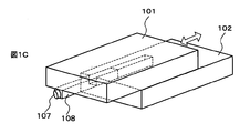
- FIG. 1C is a diagram illustrating a configuration of the electronic device according to the first embodiment of the present invention.
- FIG. 2 is a plan view showing a long state of the portable wireless device according to the second embodiment of the present invention.
- FIG. 3 is a side view showing a long state of the portable wireless device according to the second embodiment of the present invention.
- FIG. 4 is a perspective view showing a long state of the portable wireless device according to the second embodiment of the present invention.
- FIG. 5 is a plan view showing a short state of the portable wireless device according to the second embodiment of the present invention.
- FIG. 6 is a perspective view showing a short state of the portable wireless device according to the second embodiment of the present invention.
- FIG. 7 is a plan view showing a state where the portable wireless device according to the second embodiment of the present invention is in a short state and further contains an antenna.
- FIG. 8 is a perspective view showing a state in which the portable wireless device according to the second embodiment of the present invention is in a short state and further contains an antenna.
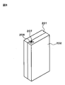
- FIG. 9 is a perspective view showing the configuration of the portable wireless device according to the first embodiment of the present invention.
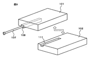
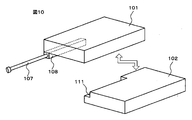
- FIG. 10 is a perspective view showing the configuration of the portable wireless device according to the first embodiment of the present invention.
- FIG. 11 is a perspective view showing a configuration of a portable wireless device according to the second embodiment of the present invention.
- an electronic apparatus is a slide-type electronic apparatus in which an upper housing 101 and a lower housing 102 are slidably coupled, and includes an upper housing.
- the body 101 has a storage portion 108 installed so as to protrude to the back side substantially parallel to the sliding direction, and a whip antenna 107 that can be stored in the storage portion 108.
- a groove 111 in which the storage portion 108 can be placed is formed, and the storage portion 108 is placed in the groove 111 when the slide is closed.
- FIGS. 1A, 1B, and 1C An electronic apparatus according to the first embodiment is shown in FIGS. 1A, 1B, and 1C.
- FIG. 1A shows an electronic device in which an upper housing and a lower housing are separated for explanation.
- FIG. 1B illustrates a state in which the upper housing and the lower housing of the electronic device illustrated in FIG. 1A are coupled.
- FIG. 1C shows the electronic device shown in FIG. 1B in a state where the antenna is housed in the housing portion.
- FIGS. 1A shows an electronic device in which an upper housing and a lower housing are separated for explanation.
- FIG. 1B illustrates a state in which the upper housing and the lower housing of the electronic device illustrated in FIG. 1A are coupled.
- FIG. 1C shows the electronic device shown in FIG. 1B in a state where the antenna is housed in the housing portion.
- FIGS. 1A shows an electronic device in which an upper housing and a lower housing are separated for explanation.
- FIG. 1B illustrates a state in which
- the electronic apparatus includes an upper housing 101, a lower housing 102 connected to the upper housing 101, and a lower housing side of the upper housing 101. And the antenna 107 housed in the housing portion 108 and the groove 111 disposed on the surface of the lower housing 102 on the upper housing side. As shown in FIG. 1B, the lower housing 102 is slidable with respect to the upper housing 101.
- the groove 111 has a shape capable of accommodating at least a part of the accommodating portion 108.
- the electronic device according to the first embodiment slides between the upper housing and the lower housing, so that the connected state in which the upper housing and the lower housing are connected takes a short state and a long state.
- the short state refers to a state where the length in the sliding direction in the connected state is short.
- the long state refers to a state in which the length in the sliding direction in the connected state is longer than that in the short state.
- the short state is also called a slide closed state.
- the long state is also called a slide open state.
- the short state and the long state can be switched by sliding the upper housing or the lower housing with respect to each other.
- the storage unit 108 that stores the antenna 107 is disposed in the upper casing 101, so that when the antenna 107 is pulled out, the antenna element is close to the upper casing 101 that may function as a ground. Can be prevented.
- the antenna characteristics can be prevented from being deteriorated by arranging the storage portion 108 in this way.
- the storage unit 108 is disposed on the surface of the upper housing 101 on the lower housing 102 side, and the groove 111 in which the storage unit 108 can be disposed is formed in the upper housing of the lower housing 102. Place on the body side.
- channel 111 is equipped with the shape which can accommodate at least one part of the accommodating part 108. FIG. Thereby, the storage portion 108 can be disposed in the groove 111. As a result, electronic devices can be made thinner and smaller.
- the groove 111 disposed in the lower housing 102 is sufficiently large enough to accommodate the storage portion 108, so that the upper housing surface of the lower housing 102 is effectively used. can do.
- the mobile terminal described in Patent Document 1 has a structure in which the back surface on the upper end side of the upper casing is extended in the thickness direction of the upper casing, and an antenna is disposed in the extended portion. It was necessary to make it shorter than the upper case. For this reason, in the long state, the exposed area of the upper casing side surface of the lower casing is reduced, and the operability of the mobile terminal is lowered.
- the groove 111 having a size that allows the storage unit 108 to be disposed on the upper housing side of the lower housing 101, thereby increasing the length of the lower housing in the longitudinal direction.
- the length of the upper casing 101 in the longitudinal direction which is the sliding direction, can be made equal to the length of the lower casing 102 in the longitudinal direction.
- the antenna 107 is desirably structured to be housed in the housing portion 108. With such a structure, a portion protruding from the periphery of the housing can be reduced, and the electronic device can be easily carried.
- the tip of the antenna 107 is preferably disposed on the side surface of the storage unit 108 on the side in which the housing slides. With such a structure, the antenna 107 can be easily pulled out of the storage portion 108.
- One of the side surfaces of the storage unit 108 on the side in which the lower housing slides with respect to the upper housing is preferably disposed at the end of the upper housing 101 on the sliding direction side. With such a configuration, the antenna 107 can be easily pulled out from the storage portion 108.
- the storage unit 108 preferably stores only the antenna 107.
- the storage unit 108 can have any shape as long as it can be disposed in the groove 111. Therefore, the groove 111 can be made small by making the storage portion 108 into a shape that only stores the antenna 107.
- the storage unit 108 can be arranged such that the longitudinal direction of the storage unit 108 is substantially parallel to the direction in which the lower housing 102 slides relative to the upper housing 101.
- the storage unit 108 can store things other than the antenna.
- the size of the storage unit 108 can be changed according to the size of the storage unit. When the size of the storage unit 108 is changed, it is desirable to change the size of the groove in accordance with the size of the storage unit.
- the shape of the storage portion 108 may be a cylinder. At least a part of the storage unit 108 may be disposed inside the upper housing 101 as shown in FIG.
- a part of the storage unit 108 in the thickness direction can be disposed inside the upper housing 101. Further, as shown in FIG. 1A, the entire storage unit 108 may be disposed on the surface of the upper housing.
- the upper casing 101 and the lower casing 102 have the same shape, but they may have different shapes.
- the lower housing 102 can be configured to slide with respect to the upper housing 101 at a distance substantially equal to the length of the lower housing 102 in the longitudinal direction. With such a configuration, the exposed area of the surface of the lower housing 102 on the upper housing side can be increased, and the operability of the electronic device can be improved. As shown in FIG.
- the groove can be arranged at the end of the lower housing in the short direction.
- the grooves are arranged in this way, it is desirable to arrange the storage portion at the end of the upper housing in the short direction.
- the antenna it is desirable to use an omnidirectional antenna such as a rod antenna or a whip antenna.
- the lower casing is slid with respect to the upper casing. This means that the upper casing and the lower casing are slid with respect to each other. is there. Therefore, it is understood that this includes a slide of the upper housing relative to the lower housing.
- the invention disclosed in Patent Document 1 eliminates the limitation of the antenna installation space by disposing the antenna in the upper stage on the upper rear side of the upper casing.
- the electronic apparatus according to this embodiment prevents deterioration of the antenna characteristics of the whip antenna without increasing the thickness dimension in the slide closed state, and ensures a large exposed area on the front surface of the lower housing in the slide open state. it can.
- a storage portion capable of containing an antenna is formed in an upper housing constituting the electronic device.
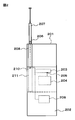
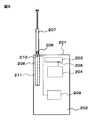
- FIGS. 2 to 4 are a plan view, a side view, and a perspective view showing the portable wireless device according to the present embodiment in a long state.
- FIGS. 5 to 6 are a plan view and a perspective view showing the portable wireless device according to the present embodiment in a short state. Further, FIGS.
- the portable wireless device according to the present embodiment has a structure in which an upper housing 201 and a lower housing 202 are connected so as to be slidable.
- a groove 211 having a shape corresponding to the storage portion 208 is disposed on the front side of the lower housing 202.
- a radio circuit 204 for processing radio communication signals and a receiving circuit 209 for processing digital television broadcast signals are installed. Near the upper end of the lower housing 202, as shown in FIG. As shown in FIG.
- the radio communication antenna 203 is connected to a radio circuit 204 provided in the lower housing 202 via a power feeding unit 205 and can transmit and receive radio signals.
- the wireless communication antenna 203 may be a multiband antenna corresponding to a plurality of frequency bands, or a single band antenna corresponding to only one frequency band.
- a whip antenna 207 for receiving digital television broadcasts is installed on the rear side of the upper casing 201, and the whip antenna 207 can be stored in a storage portion 208 that protrudes from the rear face of the upper casing 201.
- the longitudinal direction of the storage unit is arranged along the sliding direction of the upper housing 201 and the lower housing 202.
- the whip antenna 207 can be pulled out from the storage unit 208 in a direction in which the upper casing 201 or the lower casing 202 slides. Whip antenna 207 is telescopic. Furthermore, the whip antenna 207 can be bent in an arbitrary direction at the retractable portion 206. Whip antenna 207 is connected to reception circuit 209 installed in lower housing 202 via storage unit 208 and power supply unit 210, and converts a radio signal received as a digital television broadcast wave into an electrical signal. To the receiving circuit 209. By pulling out the whip antenna 207 from the storage portion 208, the whip antenna 207 can be attached to the upper housing 201 and the long housing shown in FIGS. 2, 3, and 4 and in the short state shown in FIGS.
- the antenna element of the whip antenna 207 that is pulled out is separated from both the upper housing 201 and the lower housing 202. Therefore, in the portable wireless device according to the present embodiment, the antenna characteristics of the whip antenna 207 are not deteriorated by the influence of the upper casing 201 and the lower casing 202.
- the storage unit 208 is disposed in the groove 211, so that the storage unit 208 protrudes on the back side of the upper housing 201, but the short unit is short. The total thickness of the device in the state does not increase.
- the whip antenna 7 is housed in the housing portion 208, so that there is no portion protruding from the peripheral edge of the housing, so that the carrying is not hindered.
- the upper housing 201 and the lower housing 202 can have substantially the same shape, and can have a structure in which they substantially completely overlap in a short state. Therefore, it is possible to ensure a large exposed area of the front surface of the lower housing in the long state. Therefore, the operability of the operation unit is not impaired.
- the portable wireless device is provided with a storage portion for storing a whip antenna for receiving television on the back side of the upper housing, and a groove corresponding to the storage portion is provided on the front surface of the lower housing.
- a storage portion for storing a whip antenna for receiving television on the back side of the upper housing
- a groove corresponding to the storage portion is provided on the front surface of the lower housing.
- the increase in the thickness dimension in a short state can be prevented by arranging the storage portion in the groove.
- the whip antenna since the whip antenna is installed in the upper housing, it can prevent the antenna element of the antenna from approaching the upper housing and the lower housing in both the long state and the short state, and is a good antenna The characteristics can be maintained. Furthermore, it is possible to ensure a large exposed area of the front surface of the lower housing in the long state.
- the configuration in which the circuit for processing the electrical signal converted by the whip antenna is provided in the lower casing is described as an example, but this may be provided in the upper casing.
- the use of the whip antenna is not limited to reception of digital television broadcast waves, and may be used for radio broadcast reception or wireless communication.
- an operation unit 212 on the surface of the lower housing on the upper housing side.
- the operation unit 212 includes operation keys such as direction keys and numeric keys, a touch panel, and the like.
- the exposed area of the surface of the lower casing on the upper casing side is large, that is, the area where the operation keys can be arranged is large, so that the key pitch of the operation keys can be widened.
- operation keys that are easy to operate can be arranged on the lower housing.
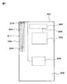
- FIG. 11 it is desirable to arrange a display unit 213 on the surface of the upper housing that faces the surface of the lower housing.
- the display unit 213 can be disposed on the surface of the upper housing on the lower housing side.
- the present invention can be applied to an electronic device that can be opened and closed.
Landscapes
- Engineering & Computer Science (AREA)
- Computer Networks & Wireless Communication (AREA)
- Telephone Set Structure (AREA)
- Support Of Aerials (AREA)
- Details Of Aerials (AREA)
Abstract
Description
スライド開閉可能な電子機器の下部筐体の側面にホイップアンテナを設置した構造においては、筐体を開いた状態でホイップアンテナを引き出すと、ホイップアンテナのアンテナエレメントが上部筐体に近接する。そのため、アースとして働く上部筐体の影響を受けて受信性能が劣化することが知られている。
そこで、この現象への対策として、上部筐体側へホイップアンテナを設置することが考えられている。
しかしながら、スライド開閉可能な電子機器においては、上部筐体には表示デバイス(Liquid Crystal Display(LCD)や有機electroluminescence(EL)表示装置等)が搭載されることが多い。このため、上部筐体にホイップアンテナを搭載するスペースを確保することは、電子機器の薄型化・小型化の点から困難である。
アンテナを上部筐体に搭載したスライド開閉可能な電子機器に関連する技術としては、特許文献1に開示される「モバイル端末機」がある。特許文献1に開示されるモバイル端末機は、上部筐体の上端側の背面を延長して上段部及び保持部を設け、下部筐体を上部筐体よりも短くした構成である。また、アンテナは上段部に配置される。
しかし、特許文献1に開示される発明のように下部筐体を上部筐体よりも短くしてしまうと、上部筐体と下部筐体とが互いにスライドできる距離が短くなる。このため、スライド開状態において下部筐体の前面の露出する面積が小さくなり、電子機器の操作性が損なわれてしまうという問題点があった。
下部筐体の前面の露出する面積が小さくなると、電子機器の操作性が損なわれる。例えば、露出する面積が小さくなると、握ることができる下部筐体の表面積が小さくなり、ユーザは電子機器を握りづらくなる。また、下部筐体の前面に実装する方向キーや数字キーなどの操作部を小さくしたり、キーピッチを狭くしたりしなければならなくなり、電子機器の操作性が損なわれる。
本発明は係る問題に鑑みてなされたものであり、本発明の目的は、上述した課題であるアンテナ特性の劣化及び操作性の低下をまねくことなく小型化・薄型化が可能な電子機器及びその製造方法を提供することにある。
また、本発明の電子機器の製造方法は、電子機器を構成する上部筐体にアンテナを内包可能な収納部を形成し、電子機器を構成する下部筐体に収納部の少なくとも一部を収容可能な溝を形成し、上部筐体と下部筐体とを収納部と溝とを対向させて連結することを特徴とする。
図1Bは、本発明の第1の実施形態に係る電子機器の構成を示す図である。
図1Cは、本発明の第1の実施形態に係る電子機器の構成を示す図である。
図2は、本発明の第2の実施形態に係る携帯無線機の長尺状態を示す平面図である。
図3は、本発明の第2の実施形態に係る携帯無線機の長尺状態を示す側面図である。
図4は、本発明の第2の実施形態に係る携帯無線機の長尺状態を示す斜視図である。
図5は、本発明の第2の実施形態に係る携帯無線機の短尺状態を示す平面図である。
図6は、本発明の第2の実施形態に係る携帯無線機の短尺状態を示す斜視図である。
図7は、本発明の第2の実施形態に係る携帯無線機の短尺状態で、さらに、アンテナを収納した状態を示す平面図である。
図8は、本発明の第2の実施の形態に係る携帯無線機の短尺状態で、さらに、アンテナを収納した状態を示す斜視図である。
図9は、本発明の第1の実施の形態に係る携帯無線機の構成を示す斜視図である。
図10は、本発明の第1の実施の形態に係る携帯無線機の構成を示す斜視図である。
図11は、本発明の第2の実施の形態に係る携帯無線機の構成を示す斜視図である。
(第1の実施形態)
図1A、図1B、に示すように、第1の実施形態に係る電子機器は、上部筐体101と下部筐体102とがスライド可能に連結されたスライド型の電子機器であって、上部筐体101は、スライド方向と略平行で背面側に突出するように設置された収納部108と、収納部108内に収納可能なホイップアンテナ107とを有し、下部筐体102の前面には、収納部108を配置可能な溝111が形成されており、スライド閉状態においては、溝111内に収納部108が配置されることを特徴とする。
このような構成とすることにより、スライド閉状態での厚さ寸法を増加させることなくホイップアンテナのアンテナ特性の劣化を防ぎ、且つ、スライド開状態での下部筐体前面の露出する面積を大きく確保できる。
第1の実施形態について、さらに、詳細に説明する。第1の実施形態に係る電子機器を図1A、図1B、図1Cに示す。図1Aは、上部筐体と下部筐体とを説明のために引き離した電子機器を示す。図1Bは、図1Aに示す電子機器の上部筐体と下部筐体とを連結させた状態のものを示す。図1Cは、図1Bに示す電子機器であって、アンテナが収納部に収納された状態のものを示す。
図1A、図1Cに示すように、第1の実施形態に係る電子機器は、上部筐体101と、上部筐体101に連結された下部筐体102と、上部筐体101の、下部筐体側の面上に配置された収納部108と、収納部108に収納されたアンテナ107と、下部筐体102の、上部筐体側の面に配置された溝111と、を有する。図1Bに示すように、下部筐体102は上部筐体101に対してスライド可能である。溝111は、収納部108の少なくとも一部を収容可能な形状を備える。
第1の実施形態の電子機器は、上部筐体と下部筐体とをスライドすることより、上部筐体と下部筐体とが連結した連結状態は短尺状態と長尺状態とをとる。短尺状態とは、連結状態におけるスライド方向の長さが短い状態を指す。長尺状態とは、連結状態におけるスライド方向の長さが、短尺状態のときよりも長い状態を指す。また、短尺状態は、スライド閉状態とも言う。一方、長尺状態は、スライド開状態とも言う。短尺状態と長尺状態は、上部筐体または下部筐体を互いに対してスライドすることにより、切り替えることが可能である。
本実施形態の電子機器では、アンテナ107を収納する収納部108を上部筐体101に配置することにより、アンテナ107を引き出したときにアンテナエレメントがアースとして機能する恐れのある上部筐体101に近接するのを防ぐことができる。従って、収納部108をこのように配置することによりアンテナ特性の劣化を防止することができる。
さらに、本実施形態の電子機器では、収納部108を上部筐体101の下部筐体102側の面上に配置し、収納部108を配置することができる溝111を下部筐体102の上部筐体側の面に配置する。そして、溝111は収納部108の少なくとも一部を収容可能な形状を備える。これにより、収納部108を溝111の中に配置させることができる。その結果、電子機器の薄型化・小型化が可能となる。
加えて、本実施形態の電子機器では、下部筐体102に配置する溝111は収納部108を配置できる大きさで十分であることにより、下部筐体102の上部筐体側の面を有効に利用することができる。特許文献1に記載のモバイル端末機は、上部筐体の上端側の背面を上部筐体の厚み方向に延長し、その延長部分にアンテナを配置する構造としているため、下部筐体の長手方向を上部筐体よりも短くする必要があった。このため、長尺状態において、下部筐体の上部筐体側の面の露出する面積が小さくなり、モバイル端末機の操作性が低下した。一方、本実施形態の電子機器は、下部筐体101の上部筐体側に収納部108を配置できる大きさの溝111を設ければ十分であることにより、下部筐体の長手方向の長さを短くする必要がない。そのため、例えば、上部筐体101の、スライド方向である長手方向の長さと下部筐体102の長手方向の長さとを等しくすることができる。その結果、上部筐体101と下部筐体102とを長尺状態において下部筐体102の上部筐体側の面の露出する面積を大きくすることができ、電子機器の操作性を向上させることができる。例えば、下部筐体102の上部筐体側の面の露出する面積を大きくすることにより、下部筐体102を握り易くなる。また、下部筐体102の上部筐体側の面に方向キーや数字キーなどの操作部を配置でき、電子機器の操作性を向上させることができる。
上述のとおり、本実施形態に示した電子機器を構成とすることにより、アンテナのアンテナ特性の劣化及び操作性の低下を防止でき、さらに、電子機器の小型化・薄型化を実現することができる。
アンテナ107は収納部108に収納できる構造にするのが望ましい。このような構造にすることにより、筐体の周縁から突出した部分を減らすことができ、電子機器を持ち運びし易い構造とすることができる。
アンテナ107の先端部は、収納部108の、筐体がスライドする方向側の側面に配置されるのが望ましい。このような構造にすることで、アンテナ107を収納部108から容易に引き出すことが可能となる。
収納部108の、下部筐体が上部筐体に対してスライドする方向側の側面の一方は、上部筐体101のスライドする方向側の端部に配置させるのが望ましい。このような構成とすることで、アンテナ107を収納部から108から容易に引き出すことが可能となる。
収納部108は、アンテナ107のみを収納するのが望ましい。収納部108は、溝111の中に配置可能であれば、任意の形状とすることができる。そこで、収納部108を、アンテナ107のみを収納する形状にすることにより、溝111を小さくすることが可能となる。その結果、下部筐体102の上部筐体側の面の露出する面積が大きくなり、電子機器の操作性が良くなる。
収納部108は、収納部108の長手方向が、下部筐体102が上部筐体101に対してスライドする方向と略平行に配置することができる。
収納部108は、アンテナ以外のものを収納することができる。収納部108の大きさは収納するものの大きさに応じて変えることができる。なお、収納部108の大きさを変えた場合は、収納部の大きさに合わせて溝の大きさを変えるのが望ましい。
収納部108の形状は筒状にしても良い。
収納部108の少なくとも一部は、図9に示すように、上部筐体101の内側に配置されても良い。例えば、収納部108の厚み方向の一部を上部筐体101の内側に配置することができる。また、図1Aに示すように、収納部108の全体が上部筐体の表面上に配置されていても良い。
図1A~図1Cに示した電子機器では、上部筐体101と下部筐体102とを同じ形状としているが、これらは異なる形状としても良い。
下部筐体102は、上部筐体101に対して下部筐体102の長手方向の長さと略等しい距離をスライドする構成とすることができる。このような構成にすることにより、下部筐体102の上部筐体側の面の露出する面積を増やすことができ、電子機器の操作性を向上させることができる。
溝は、図10に示すように、下部筐体の短手方向の端に配置させる構成とすることができる。溝をこのような配置にした場合、収納部は上部筐体の短手方向の端に配置させるのが望ましい。
アンテナには、ロッドアンテナやホイップアンテナなどの無指向性のアンテナを用いるのが望ましい。
上述の説明において、本実施形態における電子機器では、上部筐体に対して下部筐体をスライドさせると説明したが、これは、上部筐体と下部筐体とを互いに対してスライドさせるという意味である。従って、これには、下部筐体に対して上部筐体をスライドさせるものも含まれると解する。
特許文献1に開示される発明は、上部筐体の背面上端側の上段部にアンテナを配置することにより、アンテナ設置空間の制限を無くすものである。しかしながら、下部筐体を上部筐体よりも短くすると、上部筐体と下部筐体とが互いにスライドできる距離が短くなる。このため、上部筐体と下部筐体とが互いにスライドできる距離を十分に備え、アンテナを上部筐体に搭載した電子機器は実現されていなかった。
上述の問題は本実施形態に係る電子機器により解決できる。本実施形態に係る電子機器は、スライド閉状態での厚さ寸法を増加させることなくホイップアンテナのアンテナ特性の劣化を防ぎ、且つ、スライド開状態での下部筐体前面の露出する面積を大きく確保できる。
以下に、本実施形態に係る電子機器の製造方法について説明する。電子機器を構成する上部筐体にアンテナを内包可能な収納部を形成する。また、電子機器を構成する下部筐体に収納部の少なくとも一部を収容可能な溝を形成する。そして、上部筐体と下部筐体とを収納部と溝とを対向させて連結する。
(第2の実施形態)
次に、第2の実施形態に係る電子機器について図2~図9を用いて説明する。以下、電子機器が携帯無線機であり、ホイップアンテナがデジタルテレビ放送の受信用である場合の実施形態である。
図2~4は、本実施形態に係る携帯無線機であって、長尺状態のものを示す平面図、側面図、斜視図である。さらに、図5~6に本実施形態に係る携帯無線機であって短尺状態のものを示す平面図と斜視図である。さらに、図7~8に、本実施形態に係る携帯無線機であって、短尺状態であり、さらに、アンテナを収納した状態を示す平面図と斜視図である。
図2~図4に示すとおり、本実施形態に係る携帯無線機は、上部筐体201と下部筐体202とがスライド開閉可能に連結された構造である。
下部筐体202の正面側には収納部208と対応する形状の溝211が配置されている。下部筐体202の内部には、無線通信信号を処理するための無線回路204と、デジタルテレビ放送信号を処理するための受信回路209とが設置されている。下部筐体202の上端近傍には、図3に示すとおり、無線通信用アンテナ203が設置されている。無線通信用アンテナ203は、図2に示すとおり、下部筐体202内に設けられた無線回路204に給電部205を介して接続されており、無線信号を送受信可能となっている。無線通信用アンテナ203は、複数の周波数帯域に対応したマルチバンドアンテナでも良いし、一つの周波数帯域のみに対応したシングルバンドアンテナでも良い。
上部筐体201の側背面には、デジタルテレビ放送受信用のホイップアンテナ207が設置されており、ホイップアンテナ207は、上部筐体201の背面に突出する収納部208に収納可能となっている。収納部208は、収納部の長手方向が上部筐体201及び下部筐体202のスライド方向に沿って配置されている。
ホイップアンテナ207は、収納部208から、上部筐体201または下部筐体202がスライドする方向に引き出すことが可能である。また、ホイップアンテナ207は、伸縮式である。さらに、ホイップアンテナ207は可倒部206において任意の方向へ折り曲げることが可能となっている。ホイップアンテナ207は、下部筐体202内に設置された受信回路209に対して収納部208及び給電部210を介して接続されており、デジタルテレビ放送波として受信した無線信号を電気信号に変換して受信回路209へ出力する。
ホイップアンテナ207を収納部208から引き出すことにより、ホイップアンテナ207は、図2、図3、図4に示す長尺状態及び図5、図6に示す短尺状態のいずれにおいても、上部筐体201及び下部筐体202のいずれとも前後方向、すなわち上部筐体の厚み方向に重なっていない状態となる。すなわち、引き出したホイップアンテナ207のアンテナエレメントは、上部筐体201及び下部筐体202のいずれとも離された状態となる。従って、本実施形態の携帯無線機では、ホイップアンテナ207のアンテナ特性が上部筐体201や下部筐体202の影響を受けて劣化することはない。
また、図5、図6に示すように、短尺状態では、収納部208は溝211内に配置されるため、上部筐体201の背面側に収納部208が突出しているにも関わらず、短尺状態での装置全体の厚さは増加しない。従って、携帯無線機の薄型化の妨げとはならない。また、図7、図8に示すようにホイップアンテナ7を収納部208に収納することにより、筐体の周縁から突出した部分が無くなるため、持ち運びに支障をきたすことがない。
また、上部筐体201と下部筐体202とをほぼ同じ形状とし、短尺状態においてこれらがほぼ完全に重なり合う構造とすることができる。したがって長尺状態において下部筐体の前面の露出する面積を大きく確保できる。従って、操作部の操作性が損なわれることがない。
このように、本実施形態に係る携帯無線機は、上部筐体の背面側にテレビ受信用のホイップアンテナを収納する収納部を設け、この収納部に対応した形状の溝を下部筐体の前面に設けている。これにより、収納部を溝内に配置させることで短尺状態での厚さ寸法の増加を防止できる。また、ホイップアンテナは上部筐体に設置されているため、長尺状態、短尺状態のいずれの状態においても、アンテナのアンテナエレメントが上部筐体や下部筐体に近づくのを防止でき、良好なアンテナ特性を維持できる。さらに、長尺状態において下部筐体の前面の露出する面積を大きく確保できる。
上記実施形態においては、ホイップアンテナによって変換した電気信号を処理する回路が下部筐体内に設けられた構成を例としたが、これは上部筐体に設けられていても良い。
また、ホイップアンテナの用途は、デジタルテレビ放送波の受信に限定されることはなく、ラジオ放送の受信用であったり、無線通信用であったりしても良い。
下部筐体の上部筐体側の面には、図11に示すように、操作部212を配置させるのが望ましい。操作部212には方向キーや数字キーなどの操作キー、タッチパネルなどが含まれる。本実施形態に係る電子機器では、下部筐体の、上部筐体側の面の露出する面積が大きく、すなわち、操作キーを配置できる面積が大きいため、操作キーのキーピッチを広くすることができる。その結果、操作しやすい操作キーを下部筐体に配置することができる。
上部筐体の、下部筐体側の面に対向する面には、図11に示すように、表示部213を配置するのが望ましい。なお、表示部213は上部筐体の下部筐体側の面に配置することも可能である。
本発明は上記実施形態に限定されることなく、特許請求の範囲に記載した発明の範囲内で、種々の変形が可能であり、それらも本発明の範囲内に含まれるものであることはいうまでもない。
この出願は、2009年2月2日に出願された日本出願特願2009−021567を基礎とする優先権を主張し、その開示の全てをここに取り込む。
102、202 下部筐体
103、203 無線通信用アンテナ
104、204 無線回路
105、110、205、210 給電部
106,206 可倒部
107 アンテナ
108,208 収納部
109,209 受信回路
111,211 溝
207 ホイップアンテナ
212 操作部
213 表示部
Claims (11)
- 上部筐体と、
前記上部筐体に、前記上部筐体に対してスライド可能に連結された下部筐体と、
前記上部筐体の、前記下部筐体側の面上に配置された収納部と、
前記収納部に収納されたアンテナと、
前記下部筐体の、前記上部筐体側の面に配置された溝と、を有し、
前記溝は、前記収納部の少なくとも一部を収容可能な形状を備えることを特徴とする電子機器。 - 前記下部筐体が前記上部筐体に対してスライドすることにより、前記上部筐体と前記下部筐体とが連結した連結状態が、前記連結状態の前記スライドする方向の長さが短い短尺状態と、前記長さが前記短尺状態のときの長さよりも長い長尺状態とをとり、
前記短尺状態のとき、前記収納部は前記溝の中に配置されることを特徴とする請求項1に記載の電子機器。 - 前記下部筐体の、前記上部筐体側の面に、操作部が配置されている請求項1または2に記載の電子機器。
- 前記下部筐体の内部に、前記アンテナを介して送信又は受信する信号を処理する処理回路が設置されており、
前記アンテナは、前記収納部を介して前記処理回路に接続されていることを特徴とする請求項1から3のいずれか一項に記載の電子機器。 - 前記アンテナは、ホイップアンテナまたはロッドアンテナであることを特徴とする請求項1から4のいずれか一項に記載の電子機器。
- 前記アンテナは、デジタルテレビ放送の受信用であることを特徴とする請求項1から5のいずれか一項に記載の電子機器。
- 前記上部筐体に表示部が配置されていることを特徴とする請求項1から6のいずれか一項に記載の電子機器。
- 前記アンテナとは異なる第2のアンテナが、前記下部筐体の内部に配置されていることを特徴とする請求項1から7のいずれか一項に記載の電子機器。
- 前記第2のアンテナが無線通信用であることを特徴とする請求項8に記載の電子機器。
- 前記収納部は、前記アンテナのみを収納する形状を有することを特徴とする請求項1から9のいずれか一項に記載の電子機器。
- 電子機器を構成する上部筐体にアンテナを内包可能な収納部を形成し、
前記電子機器を構成する下部筐体に前記収納部の少なくとも一部を収容可能な溝を形成し、
前記上部筐体と前記下部筐体とを前記収納部と前記溝とを対向させて連結することを特徴とする電子機器の製造方法。
Priority Applications (4)
| Application Number | Priority Date | Filing Date | Title |
|---|---|---|---|
| US13/147,336 US8928534B2 (en) | 2009-02-02 | 2010-01-15 | Electronic apparatus and method for making the same |
| CN201080006448.4A CN102301525A (zh) | 2009-02-02 | 2010-01-15 | 电子设备和制造电子设备的方法 |
| JP2010548485A JP5527221B2 (ja) | 2009-02-02 | 2010-01-15 | 電子機器及びその製造方法 |
| EP20100735743 EP2393154A4 (en) | 2009-02-02 | 2010-01-15 | ELECTRONIC DEVICE AND MANUFACTURING METHOD THEREFOR |
Applications Claiming Priority (2)
| Application Number | Priority Date | Filing Date | Title |
|---|---|---|---|
| JP2009-021567 | 2009-02-02 | ||
| JP2009021567 | 2009-02-02 |
Publications (1)
| Publication Number | Publication Date |
|---|---|
| WO2010087274A1 true WO2010087274A1 (ja) | 2010-08-05 |
Family
ID=42395536
Family Applications (1)
| Application Number | Title | Priority Date | Filing Date |
|---|---|---|---|
| PCT/JP2010/050744 Ceased WO2010087274A1 (ja) | 2009-02-02 | 2010-01-15 | 電子機器及びその製造方法 |
Country Status (5)
| Country | Link |
|---|---|
| US (1) | US8928534B2 (ja) |
| EP (1) | EP2393154A4 (ja) |
| JP (1) | JP5527221B2 (ja) |
| CN (1) | CN102301525A (ja) |
| WO (1) | WO2010087274A1 (ja) |
Cited By (2)
| Publication number | Priority date | Publication date | Assignee | Title |
|---|---|---|---|---|
| JP2012079053A (ja) * | 2010-09-30 | 2012-04-19 | Nohmi Bosai Ltd | 発信機およびその収納箱 |
| JP2013162460A (ja) * | 2012-02-08 | 2013-08-19 | Dx Antenna Co Ltd | アンテナ装置 |
Families Citing this family (3)
| Publication number | Priority date | Publication date | Assignee | Title |
|---|---|---|---|---|
| CN105552523B (zh) * | 2016-01-22 | 2019-01-25 | 青岛海信移动通信技术股份有限公司 | 一种移动终端的天线和移动终端 |
| CN106876882A (zh) * | 2017-03-31 | 2017-06-20 | 安徽诚创鑫科技有限公司 | 独立式手机天线 |
| CN110492224B (zh) * | 2018-05-14 | 2021-04-23 | Oppo广东移动通信有限公司 | 电子设备和电子设备的控制方法 |
Citations (9)
| Publication number | Priority date | Publication date | Assignee | Title |
|---|---|---|---|---|
| JPH03175826A (ja) * | 1989-12-05 | 1991-07-30 | Matsushita Electric Ind Co Ltd | 携帯形電話機 |
| JP2001127516A (ja) * | 1999-10-25 | 2001-05-11 | Nec Corp | 携帯無線機 |
| JP2001251111A (ja) * | 2000-03-06 | 2001-09-14 | Nec Corp | 携帯無線機 |
| JP2006067361A (ja) * | 2004-08-27 | 2006-03-09 | Matsushita Electric Ind Co Ltd | 携帯無線機 |
| US20060097933A1 (en) * | 2004-11-10 | 2006-05-11 | Lg Electronics Inc. | Slide type mobile terminal |
| JP2006238271A (ja) * | 2005-02-28 | 2006-09-07 | Sony Ericsson Mobilecommunications Japan Inc | 携帯無線装置 |
| JP2008054274A (ja) | 2006-08-22 | 2008-03-06 | Lg Electronics Inc | モバイル端末機 |
| JP2008072382A (ja) * | 2006-09-13 | 2008-03-27 | Toshiba Corp | アンテナ装置及び無線装置 |
| JP2009021567A (ja) | 2007-06-15 | 2009-01-29 | Semiconductor Energy Lab Co Ltd | 半導体装置製造用基板及びその作製方法 |
Family Cites Families (12)
| Publication number | Priority date | Publication date | Assignee | Title |
|---|---|---|---|---|
| JP2581414B2 (ja) * | 1993-10-08 | 1997-02-12 | 日本電気株式会社 | 携帯無線機 |
| SE509140C2 (sv) * | 1997-04-10 | 1998-12-07 | Ericsson Telefon Ab L M | Antennenhet för att sända och ta emot signaler från/till en bärbar radioterminalenhet samt en bärvar radioenhet innefattande en terminalenhet |
| US6208874B1 (en) | 1998-11-02 | 2001-03-27 | Ericsson Inc. | Telephone assembly with automatic antenna adjustment |
| FR2802046B1 (fr) * | 1999-12-01 | 2002-04-19 | Sagem | Poste telephonique sans fil a antenne integree et a cache-clavier coulissant |
| US6741215B2 (en) * | 2001-07-31 | 2004-05-25 | Jerry Allen Grant | Inverted safety antenna for personal communication devices |
| JP3515559B2 (ja) * | 2002-01-09 | 2004-04-05 | 日本アンテナ株式会社 | 多周波用アンテナ |
| US7106260B2 (en) | 2004-02-17 | 2006-09-12 | Samsung Electronics Co., Ltd. | Antenna device for portable wireless terminal |
| US7181257B2 (en) * | 2004-12-28 | 2007-02-20 | Motorola, Inc. | Slider mechanism for handheld devices |
| CN101124806B (zh) * | 2005-02-18 | 2011-08-03 | 富士通株式会社 | 滑动式便携电话机 |
| JP5020067B2 (ja) | 2005-03-04 | 2012-09-05 | パナソニック株式会社 | 携帯無線装置 |
| KR100683868B1 (ko) * | 2005-12-05 | 2007-02-15 | 삼성전자주식회사 | 슬라이드형 이동통신 단말장치에 적용되는 안테나 |
| US20100184493A1 (en) * | 2009-01-22 | 2010-07-22 | Chien-Hung Lin | Mobile phone |
-
2010
- 2010-01-15 JP JP2010548485A patent/JP5527221B2/ja not_active Expired - Fee Related
- 2010-01-15 EP EP20100735743 patent/EP2393154A4/en not_active Withdrawn
- 2010-01-15 CN CN201080006448.4A patent/CN102301525A/zh active Pending
- 2010-01-15 WO PCT/JP2010/050744 patent/WO2010087274A1/ja not_active Ceased
- 2010-01-15 US US13/147,336 patent/US8928534B2/en not_active Expired - Fee Related
Patent Citations (9)
| Publication number | Priority date | Publication date | Assignee | Title |
|---|---|---|---|---|
| JPH03175826A (ja) * | 1989-12-05 | 1991-07-30 | Matsushita Electric Ind Co Ltd | 携帯形電話機 |
| JP2001127516A (ja) * | 1999-10-25 | 2001-05-11 | Nec Corp | 携帯無線機 |
| JP2001251111A (ja) * | 2000-03-06 | 2001-09-14 | Nec Corp | 携帯無線機 |
| JP2006067361A (ja) * | 2004-08-27 | 2006-03-09 | Matsushita Electric Ind Co Ltd | 携帯無線機 |
| US20060097933A1 (en) * | 2004-11-10 | 2006-05-11 | Lg Electronics Inc. | Slide type mobile terminal |
| JP2006238271A (ja) * | 2005-02-28 | 2006-09-07 | Sony Ericsson Mobilecommunications Japan Inc | 携帯無線装置 |
| JP2008054274A (ja) | 2006-08-22 | 2008-03-06 | Lg Electronics Inc | モバイル端末機 |
| JP2008072382A (ja) * | 2006-09-13 | 2008-03-27 | Toshiba Corp | アンテナ装置及び無線装置 |
| JP2009021567A (ja) | 2007-06-15 | 2009-01-29 | Semiconductor Energy Lab Co Ltd | 半導体装置製造用基板及びその作製方法 |
Non-Patent Citations (1)
| Title |
|---|
| See also references of EP2393154A4 * |
Cited By (2)
| Publication number | Priority date | Publication date | Assignee | Title |
|---|---|---|---|---|
| JP2012079053A (ja) * | 2010-09-30 | 2012-04-19 | Nohmi Bosai Ltd | 発信機およびその収納箱 |
| JP2013162460A (ja) * | 2012-02-08 | 2013-08-19 | Dx Antenna Co Ltd | アンテナ装置 |
Also Published As
| Publication number | Publication date |
|---|---|
| JPWO2010087274A1 (ja) | 2012-08-02 |
| CN102301525A (zh) | 2011-12-28 |
| US8928534B2 (en) | 2015-01-06 |
| EP2393154A1 (en) | 2011-12-07 |
| EP2393154A4 (en) | 2013-01-09 |
| JP5527221B2 (ja) | 2014-06-18 |
| US20110285595A1 (en) | 2011-11-24 |
Similar Documents
| Publication | Publication Date | Title |
|---|---|---|
| US9685694B2 (en) | Antenna module and mobile terminal using the same | |
| US8933849B2 (en) | Portable wireless device | |
| US10658733B2 (en) | Mobile terminal | |
| US20070273595A1 (en) | Information equipment with a plurality of radio communication antennas | |
| US20070273594A1 (en) | Laptop personal computer with a radio communication antenna | |
| JP6234566B2 (ja) | 無線通信装置及び方法 | |
| US20110237314A1 (en) | Mobile terminal apparatus | |
| WO2014028118A1 (en) | Antennas integrated with speakers and methods for suppressing cavity modes | |
| WO2010073421A1 (ja) | 携帯無線機 | |
| JP5527221B2 (ja) | 電子機器及びその製造方法 | |
| JP5020067B2 (ja) | 携帯無線装置 | |
| US9685693B2 (en) | Multi-antenna system for mobile handsets with a predominantly metal back side | |
| CN110416685B (zh) | 电子装置 | |
| JP2006148943A (ja) | アンテナ性能の改善のための導電体を有する携帯用無線端末機 | |
| WO2006082918A1 (ja) | スライド式携帯無線機 | |
| KR20090079720A (ko) | 외장 케이스 일체형 방송 수신용 안테나를 구비한 휴대용단말기 | |
| JP4641747B2 (ja) | 携帯通信端末 | |
| KR100681759B1 (ko) | 안테나 성능 개선을 위한 도전체를 갖는 휴대용 무선단말기 | |
| US8525735B2 (en) | Foldable/slideable apparatus for radio communication with backspace for an antenna | |
| CN101562645A (zh) | 天线装置和包括该天线装置的便携式无线通信装置 | |
| KR101248169B1 (ko) | 안테나 성능개선을 위한 도전영역을 갖는 이동통신단말기 | |
| KR101091344B1 (ko) | 지상파 디엠비안테나를 구비한 폴더형 이동통신 단말기 | |
| KR20070034276A (ko) | 휴대 단말기의 안테나 장치 | |
| JP2010056781A (ja) | 無線機 | |
| JP2010183377A (ja) | アンテナの取付構造及びアンテナを備える電子機器並びに携帯電話機 |
Legal Events
| Date | Code | Title | Description |
|---|---|---|---|
| WWE | Wipo information: entry into national phase |
Ref document number: 201080006448.4 Country of ref document: CN |
|
| 121 | Ep: the epo has been informed by wipo that ep was designated in this application |
Ref document number: 10735743 Country of ref document: EP Kind code of ref document: A1 |
|
| WWE | Wipo information: entry into national phase |
Ref document number: 2010548485 Country of ref document: JP |
|
| WWE | Wipo information: entry into national phase |
Ref document number: 13147336 Country of ref document: US Ref document number: 2010735743 Country of ref document: EP |
|
| NENP | Non-entry into the national phase |
Ref country code: DE |