WO2010087384A1 - 電池及び電池の製造方法と、電池における巻芯の製造方法及び巻芯製造装置並びに巻芯 - Google Patents
電池及び電池の製造方法と、電池における巻芯の製造方法及び巻芯製造装置並びに巻芯 Download PDFInfo
- Publication number
- WO2010087384A1 WO2010087384A1 PCT/JP2010/051089 JP2010051089W WO2010087384A1 WO 2010087384 A1 WO2010087384 A1 WO 2010087384A1 JP 2010051089 W JP2010051089 W JP 2010051089W WO 2010087384 A1 WO2010087384 A1 WO 2010087384A1
- Authority
- WO
- WIPO (PCT)
- Prior art keywords
- sheet
- core
- battery
- winding
- manufacturing
- Prior art date
- Legal status (The legal status is an assumption and is not a legal conclusion. Google has not performed a legal analysis and makes no representation as to the accuracy of the status listed.)
- Ceased
Links
Images




Classifications
-
- H—ELECTRICITY
- H01—ELECTRIC ELEMENTS
- H01M—PROCESSES OR MEANS, e.g. BATTERIES, FOR THE DIRECT CONVERSION OF CHEMICAL ENERGY INTO ELECTRICAL ENERGY
- H01M10/00—Secondary cells; Manufacture thereof
- H01M10/04—Construction or manufacture in general
- H01M10/0431—Cells with wound or folded electrodes
-
- H—ELECTRICITY
- H01—ELECTRIC ELEMENTS
- H01M—PROCESSES OR MEANS, e.g. BATTERIES, FOR THE DIRECT CONVERSION OF CHEMICAL ENERGY INTO ELECTRICAL ENERGY
- H01M10/00—Secondary cells; Manufacture thereof
- H01M10/04—Construction or manufacture in general
- H01M10/0404—Machines for assembling batteries
- H01M10/0409—Machines for assembling batteries for cells with wound electrodes
-
- H—ELECTRICITY
- H01—ELECTRIC ELEMENTS
- H01M—PROCESSES OR MEANS, e.g. BATTERIES, FOR THE DIRECT CONVERSION OF CHEMICAL ENERGY INTO ELECTRICAL ENERGY
- H01M6/00—Primary cells; Manufacture thereof
- H01M6/005—Devices for making primary cells
-
- H—ELECTRICITY
- H01—ELECTRIC ELEMENTS
- H01M—PROCESSES OR MEANS, e.g. BATTERIES, FOR THE DIRECT CONVERSION OF CHEMICAL ENERGY INTO ELECTRICAL ENERGY
- H01M6/00—Primary cells; Manufacture thereof
- H01M6/02—Details
-
- Y—GENERAL TAGGING OF NEW TECHNOLOGICAL DEVELOPMENTS; GENERAL TAGGING OF CROSS-SECTIONAL TECHNOLOGIES SPANNING OVER SEVERAL SECTIONS OF THE IPC; TECHNICAL SUBJECTS COVERED BY FORMER USPC CROSS-REFERENCE ART COLLECTIONS [XRACs] AND DIGESTS
- Y02—TECHNOLOGIES OR APPLICATIONS FOR MITIGATION OR ADAPTATION AGAINST CLIMATE CHANGE
- Y02E—REDUCTION OF GREENHOUSE GAS [GHG] EMISSIONS, RELATED TO ENERGY GENERATION, TRANSMISSION OR DISTRIBUTION
- Y02E60/00—Enabling technologies; Technologies with a potential or indirect contribution to GHG emissions mitigation
- Y02E60/10—Energy storage using batteries
-
- Y—GENERAL TAGGING OF NEW TECHNOLOGICAL DEVELOPMENTS; GENERAL TAGGING OF CROSS-SECTIONAL TECHNOLOGIES SPANNING OVER SEVERAL SECTIONS OF THE IPC; TECHNICAL SUBJECTS COVERED BY FORMER USPC CROSS-REFERENCE ART COLLECTIONS [XRACs] AND DIGESTS
- Y02—TECHNOLOGIES OR APPLICATIONS FOR MITIGATION OR ADAPTATION AGAINST CLIMATE CHANGE
- Y02P—CLIMATE CHANGE MITIGATION TECHNOLOGIES IN THE PRODUCTION OR PROCESSING OF GOODS
- Y02P70/00—Climate change mitigation technologies in the production process for final industrial or consumer products
- Y02P70/50—Manufacturing or production processes characterised by the final manufactured product
-
- Y—GENERAL TAGGING OF NEW TECHNOLOGICAL DEVELOPMENTS; GENERAL TAGGING OF CROSS-SECTIONAL TECHNOLOGIES SPANNING OVER SEVERAL SECTIONS OF THE IPC; TECHNICAL SUBJECTS COVERED BY FORMER USPC CROSS-REFERENCE ART COLLECTIONS [XRACs] AND DIGESTS
- Y10—TECHNICAL SUBJECTS COVERED BY FORMER USPC
- Y10T—TECHNICAL SUBJECTS COVERED BY FORMER US CLASSIFICATION
- Y10T29/00—Metal working
- Y10T29/49—Method of mechanical manufacture
- Y10T29/49002—Electrical device making
- Y10T29/49108—Electric battery cell making
-
- Y—GENERAL TAGGING OF NEW TECHNOLOGICAL DEVELOPMENTS; GENERAL TAGGING OF CROSS-SECTIONAL TECHNOLOGIES SPANNING OVER SEVERAL SECTIONS OF THE IPC; TECHNICAL SUBJECTS COVERED BY FORMER USPC CROSS-REFERENCE ART COLLECTIONS [XRACs] AND DIGESTS
- Y10—TECHNICAL SUBJECTS COVERED BY FORMER USPC
- Y10T—TECHNICAL SUBJECTS COVERED BY FORMER US CLASSIFICATION
- Y10T29/00—Metal working
- Y10T29/53—Means to assemble or disassemble
- Y10T29/5313—Means to assemble electrical device
- Y10T29/53135—Storage cell or battery
Definitions
- the present invention provides a laminated electrode member along a peripheral surface of a core while producing a laminated electrode member with a sheet-like positive electrode and a negative electrode and sheet-like separators alternately inserted into the two electrodes.
- the present invention relates to a battery manufactured by winding a member, a manufacturing method thereof, a manufacturing method of a core in the battery, a core manufacturing apparatus, and a core.
- a cylindrical core is formed, while a sheet-like positive electrode and a negative electrode are wound around the core via a sheet-like separator to form a cylindrical type.
- a power generation element is manufactured, and then a cylindrical power generation element is pressed radially inward from both sides to complete a long elliptical power generation element (see Patent Document 1).
- the cylindrical power generation element is pressed from both sides to produce a long elliptical power generation element, so the core itself is also deformed into a long ellipse. For this reason, it is thought that the intensity
- the present invention provides an inexpensive and high-strength battery, a method for manufacturing the battery, a method for manufacturing a core in the battery, a core manufacturing apparatus, and a core.
- a battery manufacturing method is wound using a core manufacturing apparatus that includes a pair of winding shafts 5 and 5 that are arranged around a rotation center and rotate around the rotation center. While producing the laminated electrode member 25 by the 1st process which manufactures the core 20, the sheet-like positive electrode 21 and the negative electrode 22, and the sheet-like separators 23 and 23, a laminated electrode is formed on the surrounding surface of the said winding core 20.
- the battery manufacturing method including the second step of winding the member 25, in the first step, a sheet S having a strength higher than that of the separator is inserted between the winding shafts 5 and 5, and a pair of After the winding shafts 5 and 5 are rotated by a predetermined angle, the winding core 20 is manufactured by adhering or welding the overlapping portions of the sheets S.
- the sheet S is inserted between both the winding shafts 5 and 5, and the pair of winding shafts 5 and 5 are fixed at a predetermined angle with the end portion of the sheet S or the vicinity thereof being fixed to one winding shaft 5, for example.
- the core 20 is manufactured.
- the sheet S is wound by rotating the pair of winding shafts 5 and 5 by a predetermined angle without fixing the sheet S inserted between the winding shafts 5 and 5 to the winding shaft 5, Manufactured.
- the curved portion protrudes in different directions, exhibits an elliptical outer shape, and the portion of the sheet S arranged so as to be obliquely spanned inside the annular portion of the sheet S is provided.
- the existing winding core 20 will be manufactured, and will be reinforced with respect to pressing from the short axis direction and the long axis direction. Therefore, the strength is increased as compared with a conventional core manufactured by pressing a cylindrical core and deforming it into a long ellipse (cross-sectional shape).
- the battery can suppress the bending of the positive and negative electrode plates, which is caused when the battery is continuously used at a high temperature, and can also suppress the decrease in the discharge capacity of the battery due to the bending.
- the manufacturing method of the core which concerns on this invention is the method of manufacturing the core 20 using the core manufacturing apparatus provided with a pair of winding shafts 5 and 5 arrange
- the sheet S is inserted between the winding shafts 5 and 5, the pair of winding shafts 5 and 5 are rotated by a predetermined angle, and then the overlapping portions of the sheet S are joined by adhesion or welding.
- the sheet S is inserted between the winding shafts 5 and 5, and the pair of winding shafts 5 and 5 is at least 1 in a state where the end portion of the sheet S or the vicinity thereof is fixed to the one winding shaft 5.
- the core 20 is manufactured. Further, for example, the pair of winding shafts 5, 5 is rotated without fixing the end portion of the sheet S inserted between the winding shafts 5, 5 or the vicinity thereof to the one winding shaft 5.
- a core is manufactured.
- the curved portion protrudes in different directions, has an elliptical outer shape, and the portion of the sheet S arranged so as to be obliquely spanned inside the annular portion of the sheet S is provided.
- the existing winding core 20 will be manufactured, and will be reinforced with respect to pressing from the short axis direction and the long axis direction. Therefore, the strength is increased as compared with a conventional core manufactured by pressing a cylindrical core and deforming it into a long ellipse (cross-sectional shape).
- the winding core manufacturing apparatus includes a pair of winding shafts 5 and 5 that are arranged around the rotation center and rotate around the rotation center.
- the sheet insertion means 10 for inserting the sheet S and the joining means 15 and 15 for joining the overlapping portions of the sheet S by adhesion or welding while the pair of winding shafts 5 and 5 are rotated by a predetermined angle are provided.
- the apparatus since it is not necessary to provide a complicated mechanism for manufacturing the winding core, the apparatus can be configured easily and inexpensively.
- the core according to the present invention is configured using the sheet S, and one end of the sheet S is joined to a predetermined portion of the sheet S, while the other end of the sheet S is another predetermined portion of the sheet S. It is characterized by being arranged so that the sheets S are joined and spanned inside the annular portion of the sheet S.
- the inner surface side of one end portion of the sheet S is joined to the outer surface side of a predetermined portion of the sheet S, while the inner surface side of the other end portion of the sheet S is connected to another predetermined portion of the sheet S. It is also possible to adopt a configuration in which the sheet S is joined to the inner surface side of the places and arranged so as to be hung inside the annular portion of the sheet S between the joint places.
- the curved portions having substantially the same size are formed in different directions, and there is a portion of the sheet S that is disposed so as to be obliquely spanned inside the annular portion of the sheet S.
- the strength of the core is improved.
- the inner surface side of one end portion of the sheet S is joined to the outer surface side of a predetermined portion of the sheet S, while the outer surface side of the other end portion of the sheet S is connected to another predetermined surface of the sheet S. It is also possible to adopt a configuration in which the sheet S is joined to the inner surface side of the places and arranged so as to be hung inside the annular portion of the sheet S between the joint places.
- curved portions having substantially the same size are formed in different directions, and there is a portion of the sheet S arranged so that the curved portion is formed inside the annular portion of the sheet S. . That is, an annular portion is formed by a pair of curved portions formed in different directions, and one of the curved portions and the curved portion formed inside the annular portion. A ring-shaped part is formed. Therefore, the strength of the core is improved by the three curved portions.
- the battery according to the present invention is characterized in that any one of the respective cores is provided.
- a positive electrode and a negative electrode resulting from expansion and contraction of the active material such as when the battery is continuously used in a high temperature place or overcharged. Is suppressed, and a decrease in the discharge capacity of the battery due to the bending is also suppressed. That is, a battery with significantly improved performance can be provided.
- a sheet for manufacturing a core is inserted between the pair of winding shafts, and then the pair of winding shafts are rotated by a predetermined angle to manufacture the core. Therefore, it is possible to manufacture a battery that is inexpensive, simple, and high in strength.
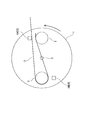
- the top view which shows the battery manufacturing apparatus which concerns on one Embodiment of this invention, and shows the state by which the sheet
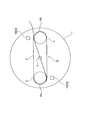
- the top view which shows the state which pressed and fixed the inserted sheet
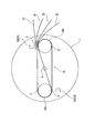
- the top view which shows the state which rotated the table half from the state of FIG.
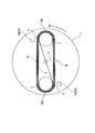
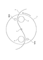
- the top view which shows the state which rotates the table another half and manufactures the core of the shape which flattened the character of "6".
- the top view which shows the state which produces a laminated electrode member by inserting a sheet-like separator alternately with respect to a sheet-like positive electrode and a negative electrode.
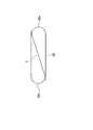
- (A) is the schematic of the core which concerns on this embodiment
- (b) is the schematic which showed another embodiment of the core of this invention.
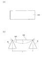
- (A) is a top view of the sample used for an intensity
- (b) is a figure which showed an example of the test apparatus.
- the winding core manufacturing apparatus includes a table 1 that is rotatably provided, a pair of winding shafts 5 and 5 that are disposed with the rotation center of the table 1 interposed therebetween, and a resin-made material between the winding shafts 5 and 5.
- a chuck 15 15A, 15B
- the table 1 has a disk shape, and a rotating shaft 2 is fixed at the center. Then, a pair of winding shafts 5 and 5 are disposed at positions (line-symmetric positions) at both ends of the diameter passing through the rotation shaft 2. In the present embodiment, the table 1 is configured to rotate counterclockwise.
- the winding shaft 5 is disposed at the peripheral edge of the table 1 and is positioned in the horizontal direction when FIG. 1 is viewed from the front. As the table 1 rotates, both winding shafts 5 and 5 revolve around the rotation center at least once. By this revolution, both winding shafts 5 and 5 take up the sheet S inserted from the sheet insertion means 10 while applying tension to the sheet S.
- the sheet insertion means 10 is disposed obliquely above the right winding shaft 5 when viewed from the front in FIG. 1 and is inserted from the rotation direction of the right winding shaft 5 toward the rotation direction of the left winding shaft 5. .
- the chucks 15A and 15B are disposed in front of both the winding shafts 5 and 5 and are provided so as to be able to move forward and backward so as to approach and separate from the winding shafts 5 and 5, as described above. Means for heat welding are provided.
- the sheet S has a thickness of, for example, 40 to 300 ⁇ m, and a material of, for example, any one of polyethylene (PE), polypropylene (PP), polyphenylene sulfide (PPS), and polyethylene terephthalate (PET). You can choose.
- PE polyethylene
- PP polypropylene
- PPS polyphenylene sulfide
- PET polyethylene terephthalate
- the sheet S is inserted between the winding shafts 5 and 5 by the sheet insertion means 10.
- one chuck 15 ⁇ / b> A is moved forward so as to be close to both winding shafts 5 and 5, and the end portion of the sheet S is pressed and fixed. That is, in the state where the surface of the sheet S is pressed and fixed to the rotation side surface of one winding shaft 5, the back surface of the sheet S comes into contact with the rotation side surface of the other winding shaft 5. That is, the sheet S is slanted around the winding shafts 5 and 5.
- the sheet S is wound along the peripheral surface of the other winding shaft 5 as shown in FIG.
- the chuck 15A is configured to be movable (retractable) in the direction of the rotation axis, for example, so that the sheet S does not entrain one chuck 15A during this half rotation.
- the chuck 15B is configured to be movable (retractable) in the direction of the rotation axis, for example, so that the sheet S does not entrain the other chuck 15B during this half rotation.
- the rotation of the table 1 is stopped, and then the chucks 15A and 15B are moved in the directions indicated by the arrows (directions close to the winding shafts 5 and 5).
- the winding core 20 is manufactured by cutting the sheet S on the winding end side while bonding (or heat welding) the portions of both curved portions of the sheet S.
- the table 1 is rotated once, but may be rotated two to three times.
- the inner surface side of one end portion of the sheet S is joined to the outer surface side of a predetermined portion of the sheet S, and the inner surface side of the other end portion of the sheet S is separated from the sheet S, as shown in FIG.
- the shape of “6” is flattened by applying pressure from the direction intersecting the surface of the sheet S.
- the curved portions 20a and 20a having substantially the same size are formed in different directions, and there is a portion of the sheet S that is arranged so as to be slanted over the annular portion of the sheet S. Therefore, the strength of the core is improved.
- a pair of sheet-like separators 23 are sent out by a sending means (not shown), and one ends of both separators 23, 23 are overlapped and joined to the joint A of the core 20. . Therefore, the tension of the wound sheet S is maintained, in other words, the tension always acts outward so as to maintain the shape of the ellipse, and the strength of the core 20 is further improved.
- both electrodes 21 and 22 are sent out so that the separators 23 and 23 are alternately inserted into the positive electrode 21 and the negative electrode 22.
- the table 1 is rotated again, and both the electrodes 21 and 22 and the separator 23 are wound to produce the laminated electrode member 25, and the table 1 is rotated several times so as to follow the peripheral surface of the core 20.
- the battery 30 is manufactured by winding the laminated electrode member 25 on the substrate (see FIG. 6).
- the thickness of the separator 23 is, for example, 20 to 30 ⁇ m, and the material can be selected from, for example, polyethylene or polypropylene.
- the battery 30 manufactured in this way has the curved portions 20a and 20a formed on the core 20 so as to protrude in different directions. While the sheet S between the joints A and A can be reinforced diagonally across the annular portion of the sheet S while being reinforced against the pressure in the direction, the minor axis direction of the core 20 Reinforcement against the inward pressure is made. That is, the battery 30 with a large strength is manufactured regardless of the pressure applied from any direction.
- each of the sheet S and the separator 23 a rectangular sample as shown in FIG. 8A is prepared, and a strength test is performed based on the test apparatus shown in FIG. 8B. That is, a pair of support bases 60, 60 having a triangular cross section are arranged at a predetermined interval L, and the sample is placed horizontally on tops of both support bases 60, 60. From this state, how much the sheet S and the separator 23 are bent is determined by the amount of bending T, and the smaller the amount of bending T, the greater the strength. And in this invention, it is a requirement that the intensity
- the positive electrode and the negative electrode can be prevented from bending due to the expansion and contraction of the active material, and the discharge capacity of the battery due to this bending can also be suppressed. That is, a significant performance improvement is recognized.
- the inner surface side of one end portion of the sheet S is joined to the outer surface side of a predetermined portion of the sheet S, while the inner surface side of the other end portion of the sheet S is connected to the inner surface side of another predetermined portion of the sheet S. 7 (see FIG. 7A), but as shown in FIG. 7B, the inner surface side of one end of the sheet S is joined to the outer surface side of a predetermined portion of the sheet S, while the sheet S You may make it join the outer surface side of the other end part of this to the inner surface side of another predetermined location of the sheet
- the sheet S is inserted between the winding shafts 5 and 5, and the table 1 is rotated while the end portion of the sheet S is pressed and fixed by the one winding shaft 5.
- the winding shaft 5 is pressed against the back surface of the sheet S to wind up the sheet S.
- the sheet S is inserted between the winding shafts 5 and 5, and one winding shaft is inserted. 5, while pressing the front surface of the sheet S and pressing the back surface of the sheet S with the other winding shaft 5, for example, at least half-turn and press the character “S” or “8” from above and below. May be added to form a flat shape (see FIG. 11).
- the sheet S is wound in the same direction on both the winding shafts 5 and 5, and the winding core 200 having the curved portions 200a and 200a having substantially the same shape on both sides is manufactured.
- the winding core 200 has both curved portions 200a, 200a projecting in different directions, and connects the different ends of the curved portions 200a, 200a so that the linear portion is between the curved portions 200a, 200a. It is supposed to be located in. Therefore, similar to the above, it is possible to realize reinforcement against pressure from the outside and suppression of bending of the electrode plate.
- both the winding shafts 5 and 5 are controlled to be driven independently, and the surface of the sheet S is pressed by one winding shaft 5 and the back surface of the sheet S is pressed by the other winding shaft 5. You may do it.
- the pair of winding shafts 5 and 5 are arranged with the rotation center of the table 1 interposed therebetween.
- the table 1 may be rotated with the groove 50a formed along the longitudinal direction of the winding shaft 50 and the sheet S inserted in the groove 50a.
- the core 200a shown in FIG. 9 is manufactured.
- 51 in a figure shows a rotating shaft.
- the sheet S is bonded by heat welding, but may be bonded by adhesion using either hot melt or tape.
- the battery core is manufactured, but a core used for other purposes than the battery may be manufactured.
Landscapes
- Engineering & Computer Science (AREA)
- Manufacturing & Machinery (AREA)
- Chemical & Material Sciences (AREA)
- Chemical Kinetics & Catalysis (AREA)
- Electrochemistry (AREA)
- General Chemical & Material Sciences (AREA)
- Secondary Cells (AREA)
- Storage Of Web-Like Or Filamentary Materials (AREA)
- Primary Cells (AREA)
Abstract
Description
Claims (8)
- 回転中心を挟んで配置され、回転中心回りに回転する一対の巻軸(5,5)を備える巻芯製造装置を用いて巻芯(20)を製造する第一工程と、シート状の正電極(21)及び負電極(22)と、シート状のセパレータ(23,23)とで積層電極部材(25)を作製しつつ、前記巻芯(20)の周面に積層電極部材(25)を巻回する第二工程とを備えた電池の製造方法において、前記第一工程では、両巻軸(5,5)の間に、前記セパレータよりも強度が大きいシート(S)を挿入し、一対の巻軸(5,5)を所定角度回転させた後、シート(S)の重なり部位を接着あるいは溶着することにより巻芯(20)を製造するようにしたことを特徴とする電池の製造方法。
- 前記シート(S)に、前記セパレータ(23,23)の一端部を重ねて接着あるいは溶着により接合するようにしたことを特徴とする請求項1に記載の電池の製造方法。
- 回転中心を挟んで配置され、回転中心回りに回転する一対の巻軸(5,5)を備える巻芯製造装置を用いて巻芯(20)を製造する方法において、両巻軸(5,5)の間にシート(S)を挿入し、一対の巻軸(5,5)を所定角度回転させた後、シート(S)の重なり部位を接着あるいは溶着により接合するようにしたことを特徴とする巻芯の製造方法。
- 回転中心を挟んで配置され、回転中心回りに回転する一対の巻軸(5,5)を備える巻芯製造装置において、両巻軸(5,5)の間にシート(S)を挿入するシート挿入手段(10)と、一対の巻軸(5,5)を所定角度回転させた状態で、シート(S)の重なり部位を接着あるいは溶着により接合する接合手段(15,15)とを備えることを特徴とする巻芯製造装置。
- シート(S)を用いて構成され、シート(S)の一端部がシート(S)の所定箇所に接合される一方、シート(S)の他端部がシート(S)の別の所定箇所に接合され、両接合箇所間におけるシート(S)がシート(S)の環状となった部分の内部で掛け渡されるように配置されることを特徴とする巻芯。
- 前記シート(S)の一端部の内面側が前記シート(S)の所定箇所の外面側に接合される一方、前記シート(S)の他端部の内面側が前記シート(S)の別の所定箇所の内面側に接合されることを特徴とする請求項5に記載の巻芯。
- 前記シート(S)の一端部の内面側が前記シート(S)の所定箇所の外面側に接合される一方、前記シート(S)の他端部の外面側が前記シート(S)の別の所定箇所の内面側に接合されることを特徴とする請求項5に記載の巻芯。
- 前記請求項5~7のいずれかに記載の巻芯を備えたことを特徴とする電池。
Priority Applications (5)
| Application Number | Priority Date | Filing Date | Title |
|---|---|---|---|
| CN201080004893.7A CN102282714B (zh) | 2009-01-29 | 2010-01-28 | 电池和制造该电池的方法、制造电池卷芯的方法及设备和电池卷芯 |
| EP10735849.1A EP2393149B1 (en) | 2009-01-29 | 2010-01-28 | Battery and battery manufacturing method, and battery core fabrication method, core fabrication device, and core |
| JP2010548539A JP5582408B2 (ja) | 2009-01-29 | 2010-01-28 | 電池及び電池の製造方法と、電池における巻芯の製造方法及び巻芯製造装置並びに巻芯 |
| US13/146,781 US9112233B2 (en) | 2009-01-29 | 2010-01-28 | Cell and method for manufacturing the same, method and apparatus for manufacturing cell core, and cell core |
| KR1020117017183A KR101708731B1 (ko) | 2009-01-29 | 2010-01-28 | 전지 및 전지의 제조 방법과, 전지에서의 권심의 제조 방법 및 권심 제조 장치 및 권심 |
Applications Claiming Priority (2)
| Application Number | Priority Date | Filing Date | Title |
|---|---|---|---|
| JP2009-017894 | 2009-01-29 | ||
| JP2009017894 | 2009-01-29 |
Publications (1)
| Publication Number | Publication Date |
|---|---|
| WO2010087384A1 true WO2010087384A1 (ja) | 2010-08-05 |
Family
ID=42395642
Family Applications (1)
| Application Number | Title | Priority Date | Filing Date |
|---|---|---|---|
| PCT/JP2010/051089 Ceased WO2010087384A1 (ja) | 2009-01-29 | 2010-01-28 | 電池及び電池の製造方法と、電池における巻芯の製造方法及び巻芯製造装置並びに巻芯 |
Country Status (7)
| Country | Link |
|---|---|
| US (1) | US9112233B2 (ja) |
| EP (1) | EP2393149B1 (ja) |
| JP (2) | JP5582408B2 (ja) |
| KR (1) | KR101708731B1 (ja) |
| CN (1) | CN102282714B (ja) |
| TW (1) | TWI450436B (ja) |
| WO (1) | WO2010087384A1 (ja) |
Cited By (10)
| Publication number | Priority date | Publication date | Assignee | Title |
|---|---|---|---|---|
| US20130011707A1 (en) * | 2011-07-06 | 2013-01-10 | Gs Yuasa International Ltd. | Winding-type electric storage device |
| JP2013191282A (ja) * | 2012-03-12 | 2013-09-26 | Gs Yuasa Corp | 蓄電素子、電極体、芯材及び巻軸 |
| JP2013232439A (ja) * | 2012-05-01 | 2013-11-14 | Hitachi Vehicle Energy Ltd | 扁平捲回形二次電池およびその製造方法 |
| WO2014207883A1 (ja) * | 2013-06-28 | 2014-12-31 | 日立オートモティブシステムズ株式会社 | 扁平捲回形二次電池 |
| JP2015141789A (ja) * | 2014-01-28 | 2015-08-03 | 株式会社Gsユアサ | 蓄電素子及び蓄電素子の製造方法 |
| JP2016149370A (ja) * | 2016-03-28 | 2016-08-18 | 株式会社Gsユアサ | 蓄電素子、電極体及び芯材 |
| JP2017130564A (ja) * | 2016-01-20 | 2017-07-27 | 株式会社皆藤製作所 | 巻回装置 |
| CN107768737A (zh) * | 2017-11-24 | 2018-03-06 | 天津冶金职业技术学院 | 一种3mm电池电极芯绕卷用工装 |
| JP2019216115A (ja) * | 2019-09-12 | 2019-12-19 | 株式会社皆藤製作所 | 巻回装置 |
| JPWO2019235476A1 (ja) * | 2018-06-07 | 2021-06-17 | 株式会社Gsユアサ | 蓄電素子 |
Families Citing this family (4)
| Publication number | Priority date | Publication date | Assignee | Title |
|---|---|---|---|---|
| WO2012137926A1 (ja) * | 2011-04-07 | 2012-10-11 | 日産自動車株式会社 | 電極積層装置および電極積層方法 |
| WO2013164884A1 (ja) * | 2012-05-01 | 2013-11-07 | 日立ビークルエナジー株式会社 | 扁平捲回形二次電池およびその製造方法 |
| CN111354968B (zh) * | 2018-12-21 | 2025-05-27 | 江苏时代新能源科技有限公司 | 卷绕装置 |
| CN115985682B (zh) * | 2023-03-22 | 2023-06-02 | 深圳江浩电子有限公司 | 一种车载电容器 |
Citations (7)
| Publication number | Priority date | Publication date | Assignee | Title |
|---|---|---|---|---|
| JPH06168736A (ja) * | 1992-11-30 | 1994-06-14 | Sanyo Electric Co Ltd | 渦巻電極体の製造方法 |
| JPH1064589A (ja) * | 1996-08-22 | 1998-03-06 | Matsushita Electric Ind Co Ltd | 薄型電池およびその製造法 |
| JPH10270069A (ja) * | 1997-03-27 | 1998-10-09 | Mitsubishi Cable Ind Ltd | 角型電池およびその製造方法 |
| JP2000156241A (ja) * | 1998-11-19 | 2000-06-06 | Japan Storage Battery Co Ltd | 電 池 |
| JP2000340263A (ja) * | 1999-05-28 | 2000-12-08 | Japan Storage Battery Co Ltd | 非水電解質二次電池 |
| JP2001229974A (ja) * | 2000-02-16 | 2001-08-24 | Shin Kobe Electric Mach Co Ltd | 円筒形リチウムイオン電池 |
| JP2003242970A (ja) * | 2002-02-12 | 2003-08-29 | Japan Storage Battery Co Ltd | 電 池 |
Family Cites Families (10)
| Publication number | Priority date | Publication date | Assignee | Title |
|---|---|---|---|---|
| GB1340314A (en) * | 1972-04-10 | 1973-12-12 | Windings Inc | Package of elongate flexible material and method and apparatus for producing such a package |
| JPS62195860A (ja) | 1986-02-24 | 1987-08-28 | Shin Kobe Electric Mach Co Ltd | 渦巻電極体の製造法 |
| JPH06104519B2 (ja) | 1991-10-24 | 1994-12-21 | 株式会社エイチイーシー | 帯状物の巻取装置およびその巻取方法 |
| JP2001126769A (ja) | 1999-10-27 | 2001-05-11 | Shin Kobe Electric Mach Co Ltd | 円筒形リチウムイオン電池 |
| US6485859B1 (en) | 2000-11-21 | 2002-11-26 | Alfred E. Mann Foundation For Scientific Research | Resilient mandrel for battery electrode assembly |
| JP2003249257A (ja) | 2002-02-25 | 2003-09-05 | Kaido Seisakusho:Kk | 電池素子材料の捲回装置用巻芯 |
| JP2003346880A (ja) | 2002-05-24 | 2003-12-05 | Japan Storage Battery Co Ltd | 電 池 |
| JP2003346879A (ja) * | 2002-05-24 | 2003-12-05 | Japan Storage Battery Co Ltd | 電 池 |
| JP2007207649A (ja) | 2006-02-03 | 2007-08-16 | Matsushita Electric Ind Co Ltd | 角型非水電解液電池の製造法 |
| JP4656451B2 (ja) | 2008-04-03 | 2011-03-23 | トヨタ自動車株式会社 | 捲回電極体の製造方法および電極巻取装置 |
-
2010
- 2010-01-28 CN CN201080004893.7A patent/CN102282714B/zh active Active
- 2010-01-28 JP JP2010548539A patent/JP5582408B2/ja active Active
- 2010-01-28 EP EP10735849.1A patent/EP2393149B1/en active Active
- 2010-01-28 US US13/146,781 patent/US9112233B2/en active Active
- 2010-01-28 KR KR1020117017183A patent/KR101708731B1/ko active Active
- 2010-01-28 TW TW99102420A patent/TWI450436B/zh active
- 2010-01-28 WO PCT/JP2010/051089 patent/WO2010087384A1/ja not_active Ceased
-
2014
- 2014-07-18 JP JP2014147637A patent/JP5867836B2/ja active Active
Patent Citations (7)
| Publication number | Priority date | Publication date | Assignee | Title |
|---|---|---|---|---|
| JPH06168736A (ja) * | 1992-11-30 | 1994-06-14 | Sanyo Electric Co Ltd | 渦巻電極体の製造方法 |
| JPH1064589A (ja) * | 1996-08-22 | 1998-03-06 | Matsushita Electric Ind Co Ltd | 薄型電池およびその製造法 |
| JPH10270069A (ja) * | 1997-03-27 | 1998-10-09 | Mitsubishi Cable Ind Ltd | 角型電池およびその製造方法 |
| JP2000156241A (ja) * | 1998-11-19 | 2000-06-06 | Japan Storage Battery Co Ltd | 電 池 |
| JP2000340263A (ja) * | 1999-05-28 | 2000-12-08 | Japan Storage Battery Co Ltd | 非水電解質二次電池 |
| JP2001229974A (ja) * | 2000-02-16 | 2001-08-24 | Shin Kobe Electric Mach Co Ltd | 円筒形リチウムイオン電池 |
| JP2003242970A (ja) * | 2002-02-12 | 2003-08-29 | Japan Storage Battery Co Ltd | 電 池 |
Cited By (14)
| Publication number | Priority date | Publication date | Assignee | Title |
|---|---|---|---|---|
| US9196427B2 (en) | 2011-07-06 | 2015-11-24 | Gs Yuasa International Ltd. | Winding-type electric storage device |
| JP2013016440A (ja) * | 2011-07-06 | 2013-01-24 | Gs Yuasa Corp | 巻回型蓄電素子 |
| US20130011707A1 (en) * | 2011-07-06 | 2013-01-10 | Gs Yuasa International Ltd. | Winding-type electric storage device |
| JP2013191282A (ja) * | 2012-03-12 | 2013-09-26 | Gs Yuasa Corp | 蓄電素子、電極体、芯材及び巻軸 |
| JP2013232439A (ja) * | 2012-05-01 | 2013-11-14 | Hitachi Vehicle Energy Ltd | 扁平捲回形二次電池およびその製造方法 |
| WO2014207883A1 (ja) * | 2013-06-28 | 2014-12-31 | 日立オートモティブシステムズ株式会社 | 扁平捲回形二次電池 |
| JPWO2014207883A1 (ja) * | 2013-06-28 | 2017-02-23 | 日立オートモティブシステムズ株式会社 | 扁平捲回形二次電池 |
| JP2015141789A (ja) * | 2014-01-28 | 2015-08-03 | 株式会社Gsユアサ | 蓄電素子及び蓄電素子の製造方法 |
| JP2017130564A (ja) * | 2016-01-20 | 2017-07-27 | 株式会社皆藤製作所 | 巻回装置 |
| JP2016149370A (ja) * | 2016-03-28 | 2016-08-18 | 株式会社Gsユアサ | 蓄電素子、電極体及び芯材 |
| CN107768737A (zh) * | 2017-11-24 | 2018-03-06 | 天津冶金职业技术学院 | 一种3mm电池电极芯绕卷用工装 |
| JPWO2019235476A1 (ja) * | 2018-06-07 | 2021-06-17 | 株式会社Gsユアサ | 蓄電素子 |
| JP7264161B2 (ja) | 2018-06-07 | 2023-04-25 | 株式会社Gsユアサ | 蓄電素子 |
| JP2019216115A (ja) * | 2019-09-12 | 2019-12-19 | 株式会社皆藤製作所 | 巻回装置 |
Also Published As
| Publication number | Publication date |
|---|---|
| CN102282714B (zh) | 2014-03-05 |
| EP2393149A4 (en) | 2017-01-18 |
| EP2393149B1 (en) | 2018-03-14 |
| JP2014239049A (ja) | 2014-12-18 |
| JP5582408B2 (ja) | 2014-09-03 |
| KR20110131170A (ko) | 2011-12-06 |
| US9112233B2 (en) | 2015-08-18 |
| TWI450436B (zh) | 2014-08-21 |
| TW201036238A (en) | 2010-10-01 |
| JP5867836B2 (ja) | 2016-02-24 |
| CN102282714A (zh) | 2011-12-14 |
| KR101708731B1 (ko) | 2017-02-21 |
| EP2393149A1 (en) | 2011-12-07 |
| JPWO2010087384A1 (ja) | 2012-08-02 |
| US20110287293A1 (en) | 2011-11-24 |
Similar Documents
| Publication | Publication Date | Title |
|---|---|---|
| JP5582408B2 (ja) | 電池及び電池の製造方法と、電池における巻芯の製造方法及び巻芯製造装置並びに巻芯 | |
| JP3551365B2 (ja) | 扁平形状巻回型電極電池 | |
| US9620755B2 (en) | Secondary battery manufacturing method, secondary battery, welding apparatus thereof | |
| JP5337366B2 (ja) | 電池製造方法及び電池 | |
| US8956748B2 (en) | Battery | |
| JP4803201B2 (ja) | 捲回型電池および捲回型電池の製造方法 | |
| JP2014041724A (ja) | 蓄電装置、及び電極組立体の製造方法 | |
| JP2009193750A (ja) | 非水系二次電池用極板群の製造方法およびそれを用いた非水系二次電池用極板群と非水系二次電池 | |
| JP2012129098A (ja) | 二次電池の製造方法および製造装置 | |
| CN107302109B (zh) | 卷绕式电芯 | |
| JP5341091B2 (ja) | 電気エネルギー貯蔵体の製造方法及び装置 | |
| JP2011076862A (ja) | 巻回型電池、及び巻回型電池用発電体の製造方法 | |
| JP2020522093A (ja) | 電極組立体及びその製造方法 | |
| JP2009181812A (ja) | 捲回型電池およびその製造方法 | |
| WO2013031937A1 (ja) | リチウムイオン二次電池 | |
| JP6104383B2 (ja) | 扁平捲回形二次電池 | |
| CN116544526A (zh) | 卷绕式电芯 | |
| JP2011077105A (ja) | 電気二重層キャパシタ及びその製造方法 | |
| CN109952680B (zh) | 包括圆柱形果冻卷的锂二次电池 | |
| CN107302110A (zh) | 卷绕式电芯 | |
| JP6863192B2 (ja) | 組電池の製造方法 | |
| JP6318887B2 (ja) | 蓄電素子 | |
| JP7146386B2 (ja) | 蓄電素子の製造方法 | |
| JP7742859B2 (ja) | 蓄電装置の製造方法 | |
| US12620616B2 (en) | Electrode assembly for secondary battery and method of manufacturing same |
Legal Events
| Date | Code | Title | Description |
|---|---|---|---|
| WWE | Wipo information: entry into national phase |
Ref document number: 201080004893.7 Country of ref document: CN |
|
| 121 | Ep: the epo has been informed by wipo that ep was designated in this application |
Ref document number: 10735849 Country of ref document: EP Kind code of ref document: A1 |
|
| WWE | Wipo information: entry into national phase |
Ref document number: 2010548539 Country of ref document: JP |
|
| ENP | Entry into the national phase |
Ref document number: 20117017183 Country of ref document: KR Kind code of ref document: A |
|
| WWE | Wipo information: entry into national phase |
Ref document number: 13146781 Country of ref document: US |
|
| NENP | Non-entry into the national phase |
Ref country code: DE |
|
| WWE | Wipo information: entry into national phase |
Ref document number: 2010735849 Country of ref document: EP |