WO2010089833A1 - 光画像計測装置 - Google Patents
光画像計測装置 Download PDFInfo
- Publication number
- WO2010089833A1 WO2010089833A1 PCT/JP2009/006711 JP2009006711W WO2010089833A1 WO 2010089833 A1 WO2010089833 A1 WO 2010089833A1 JP 2009006711 W JP2009006711 W JP 2009006711W WO 2010089833 A1 WO2010089833 A1 WO 2010089833A1
- Authority
- WO
- WIPO (PCT)
- Prior art keywords
- image
- optical system
- optical
- measured
- light
- Prior art date
- Legal status (The legal status is an assumption and is not a legal conclusion. Google has not performed a legal analysis and makes no representation as to the accuracy of the status listed.)
- Ceased
Links
Images
Classifications
-
- G—PHYSICS
- G01—MEASURING; TESTING
- G01B—MEASURING LENGTH, THICKNESS OR SIMILAR LINEAR DIMENSIONS; MEASURING ANGLES; MEASURING AREAS; MEASURING IRREGULARITIES OF SURFACES OR CONTOURS
- G01B11/00—Measuring arrangements characterised by the use of optical techniques
- G01B11/22—Measuring arrangements characterised by the use of optical techniques for measuring depth
-
- A—HUMAN NECESSITIES
- A61—MEDICAL OR VETERINARY SCIENCE; HYGIENE
- A61B—DIAGNOSIS; SURGERY; IDENTIFICATION
- A61B3/00—Apparatus for testing the eyes; Instruments for examining the eyes
- A61B3/10—Objective types, i.e. instruments for examining the eyes independent of the patients' perceptions or reactions
- A61B3/102—Objective types, i.e. instruments for examining the eyes independent of the patients' perceptions or reactions for optical coherence tomography [OCT]
-
- G—PHYSICS
- G01—MEASURING; TESTING
- G01B—MEASURING LENGTH, THICKNESS OR SIMILAR LINEAR DIMENSIONS; MEASURING ANGLES; MEASURING AREAS; MEASURING IRREGULARITIES OF SURFACES OR CONTOURS
- G01B9/00—Measuring instruments characterised by the use of optical techniques
- G01B9/02—Interferometers
- G01B9/02015—Interferometers characterised by the beam path configuration
- G01B9/02029—Combination with non-interferometric systems, i.e. for measuring the object
- G01B9/0203—With imaging systems
-
- G—PHYSICS
- G01—MEASURING; TESTING
- G01B—MEASURING LENGTH, THICKNESS OR SIMILAR LINEAR DIMENSIONS; MEASURING ANGLES; MEASURING AREAS; MEASURING IRREGULARITIES OF SURFACES OR CONTOURS
- G01B9/00—Measuring instruments characterised by the use of optical techniques
- G01B9/02—Interferometers
- G01B9/02041—Interferometers characterised by particular imaging or detection techniques
- G01B9/02044—Imaging in the frequency domain, e.g. by using a spectrometer
-
- G—PHYSICS
- G01—MEASURING; TESTING
- G01B—MEASURING LENGTH, THICKNESS OR SIMILAR LINEAR DIMENSIONS; MEASURING ANGLES; MEASURING AREAS; MEASURING IRREGULARITIES OF SURFACES OR CONTOURS
- G01B9/00—Measuring instruments characterised by the use of optical techniques
- G01B9/02—Interferometers
- G01B9/02055—Reduction or prevention of errors; Testing; Calibration
- G01B9/02062—Active error reduction, i.e. varying with time
- G01B9/02063—Active error reduction, i.e. varying with time by particular alignment of focus position, e.g. dynamic focussing in optical coherence tomography
-
- G—PHYSICS
- G01—MEASURING; TESTING
- G01B—MEASURING LENGTH, THICKNESS OR SIMILAR LINEAR DIMENSIONS; MEASURING ANGLES; MEASURING AREAS; MEASURING IRREGULARITIES OF SURFACES OR CONTOURS
- G01B9/00—Measuring instruments characterised by the use of optical techniques
- G01B9/02—Interferometers
- G01B9/02055—Reduction or prevention of errors; Testing; Calibration
- G01B9/02062—Active error reduction, i.e. varying with time
- G01B9/02067—Active error reduction, i.e. varying with time by electronic control systems, i.e. using feedback acting on optics or light
- G01B9/02068—Auto-alignment of optical elements
-
- G—PHYSICS
- G01—MEASURING; TESTING
- G01B—MEASURING LENGTH, THICKNESS OR SIMILAR LINEAR DIMENSIONS; MEASURING ANGLES; MEASURING AREAS; MEASURING IRREGULARITIES OF SURFACES OR CONTOURS
- G01B9/00—Measuring instruments characterised by the use of optical techniques
- G01B9/02—Interferometers
- G01B9/02083—Interferometers characterised by particular signal processing and presentation
- G01B9/02089—Displaying the signal, e.g. for user interaction
-
- G—PHYSICS
- G01—MEASURING; TESTING
- G01B—MEASURING LENGTH, THICKNESS OR SIMILAR LINEAR DIMENSIONS; MEASURING ANGLES; MEASURING AREAS; MEASURING IRREGULARITIES OF SURFACES OR CONTOURS
- G01B9/00—Measuring instruments characterised by the use of optical techniques
- G01B9/02—Interferometers
- G01B9/0209—Low-coherence interferometers
- G01B9/02091—Tomographic interferometers, e.g. based on optical coherence
-
- G—PHYSICS
- G01—MEASURING; TESTING
- G01N—INVESTIGATING OR ANALYSING MATERIALS BY DETERMINING THEIR CHEMICAL OR PHYSICAL PROPERTIES
- G01N21/00—Investigating or analysing materials by the use of optical means, i.e. using sub-millimetre waves, infrared, visible or ultraviolet light
- G01N21/17—Systems in which incident light is modified in accordance with the properties of the material investigated
- G01N21/47—Scattering, i.e. diffuse reflection
- G01N21/4795—Scattering, i.e. diffuse reflection spatially resolved investigating of object in scattering medium
Definitions
- the present invention relates to an optical image measurement device that forms an image representing a surface form or an internal form of an object to be measured using a light beam.
- optical image measurement technique that forms an image representing the surface form or internal form of an object to be measured using a light beam from a laser light source or the like has attracted attention. Since the optical image measurement technique does not have invasiveness to the human body unlike the X-ray CT apparatus, the development of application in the medical field and the biological field is particularly expected.
- Patent Document 1 discloses an apparatus to which an optical image measurement technique is applied.
- the measuring arm scans an object with a rotary turning mirror (galvanomirror), a reference mirror is installed on the reference arm, and the intensity of the interference light of the light beam from the measuring arm and the reference arm is dispersed at the exit.
- An interferometer is provided for analysis by the instrument.
- the reference arm is configured to change the phase of the reference light beam stepwise by a discontinuous value.
- Patent Document 1 uses a so-called “Fourier Domain OCT (Fourier Domain Optical Coherence Tomography)” technique.
- a low-coherence beam is irradiated onto the object to be measured, the reflected light and the reference light are superimposed to generate interference light, and the spectral intensity distribution of the interference light is acquired and subjected to Fourier transform.
- the form of the object to be measured in the depth direction (z direction) is imaged.
- the apparatus described in Patent Document 1 includes a galvanometer mirror that scans a light beam (signal light), thereby forming an image of a desired measurement target region of the object to be measured. Since this apparatus is configured to scan the light beam only in one direction (x direction) orthogonal to the z direction, the image formed by this apparatus is in the scanning direction (x direction) of the light beam. It becomes a two-dimensional tomogram in the depth direction (z direction) along.
- a plurality of two-dimensional tomographic images in the horizontal direction are formed by scanning the signal light in the horizontal direction and the vertical direction, and three-dimensional tomographic information in the measurement range is acquired based on the plurality of tomographic images.
- a technique for imaging is disclosed. Examples of the three-dimensional imaging include a method of displaying a plurality of tomographic images side by side in a vertical direction (referred to as stack data) and a method of rendering a plurality of tomographic images to form a three-dimensional image. Conceivable.
- Patent Documents 3 and 4 disclose other types of optical image measurement devices.
- Patent Document 3 scans the wavelength of light applied to an object to be measured, acquires a spectral intensity distribution based on interference light obtained by superimposing reflected light of each wavelength and reference light,
- an optical image measurement device that images the form of an object to be measured by performing Fourier transform on the object.
- Such an optical image measurement device is called a swept source type.
- the traveling direction of light is obtained by irradiating the object to be measured with light having a predetermined beam diameter, and analyzing the component of interference light obtained by superimposing the reflected light and the reference light.
- an optical image measuring device that forms an image representing a form in a cross section orthogonal to the shape.
- Such an optical image measuring device is called a full-field type or an en-face type.
- Patent Document 5 discloses a configuration in which the OCT technique is applied to the ophthalmic field. Prior to the application of the optical image measurement device to the ophthalmology field, an ophthalmologic photographing device such as a fundus camera was used (see, for example, Patent Document 6).
- the fundus imaging apparatus using the OCT technique has an advantage that images of various fundus depths can be selectively acquired as compared with a fundus camera that images the fundus surface. In addition, there is an advantage that a higher-detail image can be acquired than a fundus camera. The use of such OCT technology is expected to contribute to improvement in diagnosis accuracy and early detection of lesions.
- control lever is operated to align the apparatus optical system with the eye to be examined (S101). This operation is performed, for example, by projecting a bright spot on the eye to be examined by the alignment optical system and operating the control lever so that the bright spot displayed on the screen is arranged in a bracket-shaped scale.
- the apparatus optical system is focused (focused) on a region of interest of the eye to be examined (for example, the macula, optic nerve head, etc.) (S102).
- This operation is performed, for example, by projecting a focusing target on the eye to be examined using a predetermined optical system and operating a focusing handle. More specifically, a split bright line composed of two straight bright lines is projected as a focus target, and the focusing handle is operated so that the two bright lines are arranged in a straight line. .
- the interference image is searched and displayed (S103).
- an interference image at a desired depth position of the fundus is displayed by adjusting the optical path length of the reference light.
- the optical path length is adjusted to improve the image quality at a desired depth position.
- the adjustment of the optical path length may be performed manually by an operator, or may be performed automatically by acquiring and analyzing an interference image.
- Auto-tracking is a technique for causing a light beam (signal light) to follow the movement of the eye to be inspected so that the region of interest is arranged approximately at the center of the interference image. This technique is disclosed in, for example, Patent Documents 7 to 10.
- the apparatus acquires an interference image (S106), and further captures a fundus image (S107).
- some conventional ophthalmologic photographing apparatuses such as a fundus camera have a function of automatically taking an image by determining the alignment or focus state, but this can be applied to an optical image measuring apparatus as it is.
- the present invention has been made to solve such a problem, and an object of the present invention is to provide an optical image measurement device capable of easily performing measurement without missing measurement timing.
- the invention according to claim 1 divides low-coherence light into signal light and reference light, and the signal light passing through the object to be measured and the reference light passing through the reference object
- An optical system that generates interference light by causing interference to be detected, generates a detection signal by detecting the interference light, and image forming means that forms a tomographic image of the object to be measured based on the detection signal
- An image measurement apparatus comprising: an alignment unit that aligns the optical system with respect to an object to be measured; a focusing unit that focuses the optical system with respect to a region of interest of the object to be measured; and the optical by the alignment unit Determining means for respectively determining the suitability of the position of the system, the suitability of the in-focus state by the focusing means, and the suitability of the position of the attention area formed by the image forming means within the frame.
- the invention according to claim 2 is the optical image measurement device according to claim 1, wherein the control means is one of the position of the optical system, the in-focus state, and the position in the frame. When it is determined that at least one of them is inappropriate, acquisition of a tomographic image of the object to be measured is prohibited.
- the invention according to claim 3 is the optical image measurement device according to claim 1, further comprising display means, wherein the control means includes the position of the optical system, the in-focus state, and the frame. Warning information is displayed on the display means when it is determined that at least one of the positions in the box is inappropriate.
- the invention according to claim 4 is the optical image measurement device according to claim 1, wherein the determination unit further analyzes a tomographic image formed by the image forming unit to analyze the tomographic image.
- the control means determines whether the optical system position, the in-focus state, the position in the frame, and the image quality of the tomographic image are all appropriate. It is possible to acquire a tomographic image of the region of interest by controlling the system and the image forming means.
- the invention according to claim 5 is the optical image measurement device according to claim 4, wherein the control means includes a position of the optical system, a focused state, a position in the frame, and the tomography.
- the acquisition of the tomographic image of the measured object is prohibited when it is determined that at least one of the image quality of the image is inappropriate.
- the invention according to claim 6 is the optical image measurement device according to claim 4, further comprising display means, wherein the control means includes the position of the optical system, the in-focus state, and the inside of the frame. Warning information is displayed on the display means when it is determined that at least one of the position and the image quality of the tomographic image is inappropriate.
- the invention described in claim 7 is the optical image measurement device according to claim 4, wherein the optical system includes a polarizing plate on an optical path of the reference light, and the control means includes the tomographic image.
- the polarizing plate is controlled so that the image quality is maximized when it is determined that the image quality is inappropriate.
- the invention according to claim 8 is the optical image measurement device according to claim 1, wherein the region of interest is approximately in the center of the frame based on the tomographic image formed by the image forming means.
- Tracking means for causing the irradiation position of the signal light on the object to be measured to follow the movement of the object to be measured so that a tomographic image is arranged, and the determination means further includes irradiation of the signal light. Determining whether the tracking state of the position is appropriate or not, and when the control unit determines that the position of the optical system, the in-focus state, the position in the frame, and the tracking state are all appropriate, It is possible to acquire a tomographic image of the region of interest by controlling an optical system and the image forming unit.
- the invention according to claim 9 is the optical image measurement device according to claim 1, wherein the two-dimensional image of the object to be measured in a plane substantially orthogonal to the traveling direction of the signal light with respect to the object to be measured. And an irradiation position of the signal light on the object to be measured so that a tomographic image of the region of interest is arranged at a substantially center in the frame, based on an imaging unit that captures the two-dimensional image.
- Tracking means for following the movement of the object to be measured, and the determination means further determines the suitability of the tracking state of the irradiation position of the signal light, and the control means is a position of the optical system, When it is determined that the in-focus state, the position in the frame, and the tracking state are all appropriate, the tomographic image of the region of interest can be acquired by controlling the optical system and the image forming unit. To do that And features.
- the invention according to claim 10 is the optical image measurement device according to claim 8 or claim 9, wherein the control means includes the position of the optical system, the in-focus state, and the position in the frame. And at least one of the following states is determined to be inappropriate, acquisition of a tomographic image of the object to be measured is prohibited.
- the invention according to claim 11 is the optical image measurement device according to claim 8 or 9, further comprising display means, wherein the control means includes the position of the optical system and the in-focus state. When at least one of the position in the frame and the following state is determined to be inappropriate, warning information is displayed on the display means.
- the invention according to claim 12 divides low-coherence light into signal light and reference light, and causes interference between the signal light passing through the object to be measured and the reference light passing through the reference object.
- An optical system that generates a detection signal by detecting the interference light and an image forming unit that forms a tomographic image of the object to be measured based on the detection signal.
- An alignment means for aligning the optical system with respect to the object to be measured; a focusing means for focusing the optical system with respect to a region of interest of the object to be measured; and a tomographic image formed by the image forming means.
- Tracking means for causing the irradiation position of the signal light to the object to be measured to follow the movement of the object to be measured so that a tomographic image of the region of interest is arranged at a substantially center in the frame; Determining the suitability of the position of the optical system by means, determining the suitability of the in-focus state by the focus means, and determining the suitability of the position of the tomographic image of the region of interest formed by the image forming means in the frame And determining the suitability of the image quality of the tomogram by analyzing the tomogram formed by the image forming means, and determining the suitability of the tracking state of the irradiation position of the signal light, and the position of the optical system
- the focus state, the position in the frame, the image quality of the tomographic image, and the tracking state are all determined to be appropriate, the optical system and the image forming unit are controlled to control the region of interest. And a control unit that enables acquisition of tomographic images.
- the low-coherence light is divided into signal light and reference light, and the signal light passing through the object to be measured and the reference light passing through the reference object interfere with each other to cause interference light.
- An optical system that detects the interference light and generates a detection signal, an image forming unit that forms a tomographic image of the object to be measured based on the detection signal, and the signal light for the object to be measured
- An optical image measuring device having a photographing means for photographing a two-dimensional image of the object to be measured in a plane substantially orthogonal to the traveling direction, the alignment means for aligning the optical system with respect to the object to be measured; Based on the focusing means for focusing the optical system on the target area of the object to be measured and the captured two-dimensional image, the tomographic image of the target area is arranged approximately at the center in the frame.
- the above The follow-up means for following the movement of the object to be measured with the irradiation position of the signal light with respect to the measurement object, the suitability of the position of the optical system by the alignment means, and the suitability of the focus state by the focus means are judged. And determining the appropriateness of the position of the tomographic image in the frame of the region of interest formed by the image forming means and analyzing the tomographic image formed by the image forming means to determine the appropriateness of the image quality of the tomographic image.
- determining means for determining the suitability of the follow-up state of the irradiation position of the signal light, and the position of the optical system, the in-focus state, the position in the frame, the image quality of the tomographic image, and the follow-up state are all And a control unit that controls the optical system and the image forming unit to obtain a tomographic image of the region of interest when it is determined to be appropriate.
- the invention described in claim 14 is the optical image measuring device according to any one of claims 1, 4, 8, 8, 9, 12, and 13,
- the control means controls the optical system and the image forming means to acquire a tomographic image of the region of interest when it is determined that all are appropriate.
- the optical image measurement apparatus includes a frame of a tomographic image of an attention area of an object to be measured formed by an image forming unit, and whether or not an optical system is properly positioned by an alignment unit. In this case, it is determined whether each position is appropriate or not, and when it is determined that all three conditions are appropriate, a tomographic image of the region of interest can be acquired.
- another aspect of the optical image measurement device determines whether the image quality of the tomographic image is appropriate and whether the tracking state of the irradiation position of the signal light is appropriate. It is possible to acquire a tomographic image of a region of interest when it is determined that all of these are appropriate.
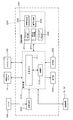
- Optical Image Measuring Device 1A Fundus Camera Unit 100 Illumination Optical System 120 Imaging Optical System 141 Scanning Unit 150 OCT Unit 160 Low Coherence Light Source 174 Reference Mirror 180 Spectrometer 184 CCD 190A alignment optical system 200 arithmetic control unit 210 control unit 220 image forming unit 230 image processing unit 231 alignment determination unit 232 focus determination unit 233 image position determination unit 234 image quality determination unit 235 tracking determination unit 240 display unit 250 operation unit 309 alignment scale 310 alignment bright spot 311 split bright line
- the configuration according to this embodiment can be applied to any type of OCT technology that scans signal light such as a swept source type.
- the configuration according to this embodiment can be applied to an OCT technique in which signal light is not scanned in the horizontal direction as in the full field type.
- the optical image measurement device 1 includes a fundus camera unit 1 ⁇ / b> A, an OCT unit 150, and an arithmetic control device 200. Each of these units may be provided in a distributed manner in a plurality of cases, or may be provided in a single case.
- the fundus camera unit 1A has an optical system that is substantially the same as that of a conventional fundus camera.
- a fundus camera is a device that photographs the fundus.
- the fundus camera is used for photographing a fundus blood vessel.
- the OCT unit 150 stores an optical system for acquiring an OCT image of the eye to be examined.
- the arithmetic and control unit 200 includes a computer that executes various arithmetic processes and control processes.
- connection line 152 One end of a connection line 152 is attached to the OCT unit 150.
- a connector 151 for connecting the connection line 152 to the retinal camera unit 1A is attached to the other end of the connection line 152.
- An optical fiber 152a is conducted inside the connection line 152 (see FIG. 3).
- the OCT unit 150 and the fundus camera unit 1A are optically connected via a connection line 152.
- the arithmetic and control unit 200 is connected to each of the fundus camera unit 1A and the OCT unit 150 via a communication line that transmits an electrical signal.
- the fundus camera unit 1A includes an optical system for forming a two-dimensional image representing the form of the fundus surface.
- the two-dimensional image of the fundus surface includes a color image and a monochrome image obtained by photographing the fundus surface, and further a fluorescent image (fluorescein fluorescent image, indocyanine green fluorescent image, etc.) and the like.
- the retinal camera unit 1A is provided with various user interfaces as in the conventional retinal camera.
- the user interface include an operation panel, a control lever (joystick), a photographing switch, a focusing handle, a display, and the like.
- Various switches and buttons are provided on the operation panel.
- the control lever is operated to three-dimensionally move a gantry provided with an operation panel or the like, or an apparatus main body incorporating an optical system with respect to the apparatus base.
- the control lever is used particularly during manual alignment operations.
- the imaging switch is provided at the upper end of the control lever, and is used to instruct acquisition of a fundus image or an OCT image.
- the photographing switch is also used when performing other functions.
- the operation panel and the control lever are provided at the position (rear surface) on the examiner side of the fundus camera unit 1A.
- the focusing handle is provided on the side surface of the apparatus main body, for example, and is used for focus adjustment (focusing). When the focusing handle is operated, a focusing lens described later is moved to change the focus state.
- the display is provided at a position on the examiner side of the fundus camera unit 1 ⁇ / b> A and displays various information such as an image acquired by the optical image measurement device 1, patient information, and imaging conditions.
- a chin rest and a forehead for holding the face of the subject are provided at a position (front surface) on the subject side of the fundus camera unit 1A.
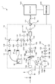
- the fundus camera unit 1A is provided with an illumination optical system 100 and a photographing optical system 120 as in the case of a conventional fundus camera.
- the illumination optical system 100 irradiates the fundus oculi Ef with illumination light.
- the imaging optical system 120 guides the fundus reflection light of the illumination light to the imaging devices 10 and 12.
- the imaging optical system 120 guides the signal light from the OCT unit 150 to the fundus oculi Ef and guides the signal light passing through the fundus oculi Ef to the OCT unit 150.
- the illumination optical system 100 includes an observation light source 101, a condenser lens 102, a photographing light source 103, a condenser lens 104, exciter filters 105 and 106, a ring translucent plate 107, a mirror 108, an LCD (Liquid Crystal Display), as in a conventional fundus camera. ) 109, an illumination aperture 110, a relay lens 111, a perforated mirror 112, and an objective lens 113.
- the observation light source 101 outputs illumination light including wavelengths in the near-infrared region, for example, in the range of about 700 nm to 800 nm. This near-infrared light is set shorter than the wavelength of light used in the OCT unit 150 (described later).
- the imaging light source 103 outputs illumination light including a wavelength in the visible region in the range of about 400 nm to 700 nm, for example.
- the illumination light output from the observation light source 101 is perforated through condenser lenses 102 and 104, (exciter filter 105 or 106) ring translucent plate 107, mirror 108, reflector 109 b, illumination diaphragm 110, and relay lens 111.
- the mirror 112 is reached. Further, the illumination light is reflected by the perforated mirror 112 and enters the eye E through the objective lens 113 to illuminate the fundus oculi Ef.
- the illumination light output from the imaging light source 103 similarly enters the eye E through the condenser lens 104 to the objective lens 113 and illuminates the fundus oculi Ef.
- the photographing optical system 120 includes an objective lens 113, a perforated mirror 112 (hole 112a), a photographing aperture 121, barrier filters 122 and 123, a focusing lens 124, a relay lens 125, a photographing lens 126, a dichroic mirror 134, and a field lens. (Field lens) 128, half mirror 135, relay lens 131, dichroic mirror 136, photographing lens 133, imaging device 10, reflection mirror 137, photographing lens 138, imaging device 12, lens 139 and LCD 140 are configured.
- the photographing optical system 120 has substantially the same configuration as a conventional fundus camera.
- the focusing lens 124 is movable in the optical axis direction of the photographing optical system 120.
- the dichroic mirror 134 reflects the fundus reflection light (having a wavelength included in the range of about 400 nm to 800 nm) of the illumination light from the illumination optical system 100.
- the dichroic mirror 134 transmits the signal light LS (for example, having a wavelength included in the range of about 800 nm to 900 nm; see FIG. 3) from the OCT unit 150.
- the dichroic mirror 136 reflects the fundus reflection light of the illumination light from the observation light source 101 and transmits the fundus reflection light of the illumination light from the imaging light source 103.
- the LCD 140 displays a fixation target (internal fixation target) for fixing the eye E to be examined.
- a fixation target (internal fixation target) for fixing the eye E to be examined.
- Light from the LCD 140 is collected by the lens 139, reflected by the half mirror 135, and reflected by the dichroic mirror 136 via the field lens 128. Further, this light is incident on the eye E through the photographing lens 126, the relay lens 125, the focusing lens 124, the aperture mirror 112 (the aperture 112a thereof), the objective lens 113, and the like. Thereby, the internal fixation target is projected onto the fundus oculi Ef.
- the fixation direction of the eye E can be changed by changing the display position of the internal fixation target on the LCD 140.
- As the fixation direction of the eye E for example, as with a conventional fundus camera, a fixation direction for acquiring an image centered on the macular portion of the fundus oculi Ef or an image centered on the optic disc is acquired. And the fixation direction for acquiring an image centered on the fundus center between the macula and the optic disc.
- the fixation position is changed, for example, by operating the operation panel.
- the imaging device 10 includes an imaging element 10a.
- the imaging device 10 can particularly detect light having a wavelength in the near infrared region. That is, the imaging device 10 functions as an infrared television camera that detects near-infrared light.
- the imaging device 10 detects near infrared light and outputs a video signal.
- the imaging element 10a is an arbitrary imaging element (area sensor) such as a CCD (Charge Coupled Devices) or a CMOS (Complementary Metal Oxide Semiconductor).
- the imaging device 12 includes an imaging element 12a.
- the imaging device 12 can particularly detect light having a wavelength in the visible region. That is, the imaging device 12 functions as a television camera that detects visible light.
- the imaging device 12 detects visible light and outputs a video signal.
- the image sensor 12a is configured by an arbitrary image sensor (area sensor), similarly to the image sensor 10a.
- the touch panel monitor 11 displays the fundus oculi image Ef ′ based on the video signals from the image sensors 10a and 12a.
- the video signal is sent to the arithmetic and control unit 200.
- the touch panel monitor 11 is an example of the display described above.
- the fundus camera unit 1A is provided with a scanning unit 141 and a lens 142.
- the scanning unit 141 scans the irradiation position of the signal light LS output from the OCT unit 150 to the fundus oculi Ef.
- the scanning unit 141 scans the signal light LS on the xy plane shown in FIG.
- the scanning unit 141 is provided with, for example, a galvanometer mirror for scanning in the x direction and a galvanometer mirror for scanning in the y direction.
- the reflector 109b of the illumination optical system 100 constitutes a focusing optical system together with the LED 109a.
- the focusing optical system projects a visual target (split bright line) used for focus adjustment onto the eye E as in a conventional fundus camera.
- the reflecting rod 109b can be inserted into and removed from the optical axis of the illumination optical system 100.
- One end of the reflecting rod 109 b has a reflecting surface that is inclined with respect to the optical axis of the illumination optical system 100.
- the output light from the LED 109a is reflected by the reflecting surface and projected onto the eye E through the same path as the illumination light.
- the focusing optical system is moved in the optical axis direction of the illumination optical system 100 in conjunction with the movement of the focusing lens 124 so that the reflecting surface of the reflecting bar 109b and the fundus oculi Ef are optically conjugate. .
- the pair of split bright lines appear to be separated in the left-right direction without being aligned on a straight line.
- the reflecting surface and the fundus oculi Ef are conjugated, the pair of split bright lines appear to be aligned. Focus adjustment can be performed using this. Such focus adjustment using split emission lines is widely used in conventional fundus cameras and the like.
- a half mirror 190 is obliquely installed on the optical path between the focusing lens 124 and the relay lens 125.
- the half mirror 190 acts to synthesize the optical path of the alignment optical system 190A shown in FIG. 2A and the optical path of the imaging optical system 120 (imaging optical path).
- the alignment optical system 190A is an optical system for projecting the alignment bright spot used for the alignment (alignment) of the optical system with respect to the eye E to the eye E.
- the alignment bright spot is an alignment (alignment in the xy direction shown in FIG. 1) that aligns the apex of the cornea of the eye E with the optical axes of the optical systems 100 and 120, and the distance between the eye E and the optical systems 100 and 120. (Z direction in FIG. 1; working distance; distance between the cornea (apex) of the eye E and the objective lens 113) (for example, Japanese Patent Laid-Open No. 11-4808) reference).
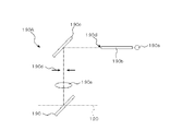
- the alignment optical system 190A includes an alignment light source 190a, a light guide 190b, a reflection mirror 190c, a two-hole aperture 190d, and a relay lens 190e together with the half mirror 190.
- the alignment light source 190a is configured by a light source such as an LED that outputs light in the near infrared region (alignment light), for example.
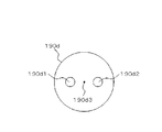
- the two-hole aperture 190d has two holes 190d1 and 190d2 as shown in FIG. 2B.
- the holes 190d1 and 190d2 are formed at positions symmetrical with respect to the center position 190d3 of the disc-shaped two-hole aperture 190d, for example.
- the two-hole aperture 190d is disposed such that the center position 190d3 is positioned on the optical axis of the alignment optical system 190A.
- Alignment light emitted from the emission end 190 ⁇ of the light guide 190b is reflected by the reflection mirror 190c and guided to the two-hole aperture 190d.
- the alignment light (a part) that has passed through the holes 190d1 and 190d2 of the two-hole aperture 190d is reflected by the half mirror 190 and guided to the perforated mirror 112 via the relay lens 190e.
- the relay lens 190e forms an intermediate image of the image of the exit end 190 ⁇ of the light guide 190b at the center position of the hole 112a of the perforated mirror 112 (position on the optical axis of the photographing optical system 120).
- the alignment light that has passed through the hole 112 a of the perforated mirror 112 is projected onto the cornea of the eye E through the objective lens 113.
- the positional relationship between the eye E and the fundus camera unit 1A is appropriate, that is, the distance (working distance) between the eye E and the fundus camera unit 1A is appropriate.
- the optical axis of the optical system of the fundus camera unit 1A and the eye axis (corneal apex position) of the eye E to be examined are (almost) coincident, two light beams (alignment light beams) formed by the two-hole aperture 190d Are projected on the eye E to be imaged at intermediate positions between the apex of the cornea and the center of curvature of the cornea.
- the corneal reflection light of the two alignment light beams is received by the image sensor 10a via the photographing optical system 120.
- An image captured by the image sensor 10a is displayed on a display device such as a touch panel monitor 11 or a display (described later) of the arithmetic and control unit 200.
- This display screen is displayed on the touch panel monitor 11, for example.
- Information presented on this display screen includes patient ID 301; left and right eye information 302, photographing light source charging information 303, photographing light amount correction information 304, photographing light amount level information 305, automatic photographing information 306, angle of view information 307, fixation position.
- Left and right eye information 302 is information indicating whether the eye E is the left eye (L) or the right eye (R).
- the imaging light source charging information 303 is information representing the charging state of the imaging light source 103 (xenon lamp).
- the photographing light amount correction information 304 is information representing a photographing light amount correction value set on the operation panel.
- the photographing light amount level information 305 is information representing a setting value of the photographing light amount.
- the automatic shooting information 306 is presented when a function for automating shooting work such as autoshoot (automatic shooting) or autofocus is turned on.
- the angle-of-view information 307 is information representing a set value of a shooting angle of view (shooting magnification).
- the fixation position information 308 is information representing a set value of the fixation position (fixation direction) of the eye E.
- the observation light quantity level information 312 is information representing a set value of the observation light quantity.
- the small pupil information 313 is presented when a small pupil diaphragm (not shown) used when the eye E is a small pupil is applied.
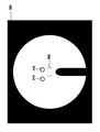
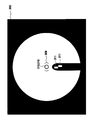
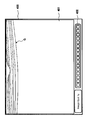
- the pair of alignment bright spots 310 are light reception images of light projected onto the eye E by the alignment optical system 190A.
- the alignment scale 309 is a parenthesis-type image that represents a position that is a movement target of the pair of alignment bright spots 310.
- the examiner performs the alignment of the optical system with respect to the eye E by operating the control lever and moving the fundus camera unit 1 ⁇ / b> A three-dimensionally so that the pair of alignment bright spots 310 enter the alignment scale 309. .
- each alignment luminescent spot 310 in the display screen is specified, a shift between each specified position and the alignment scale 309 is obtained, and the fundus camera unit 1A is moved so as to cancel this shift. To do so.
- the position of each alignment bright spot 310 can be determined by, for example, obtaining the brightness distribution of each alignment bright spot and obtaining the center of gravity position based on this brightness distribution. Since the position of the alignment scale 309 is constant, the deviation can be obtained by obtaining the displacement between the center position and the gravity center position, for example.
- the movement direction and movement distance of the fundus camera unit 1A are set as unit movement distances in each of the preset x, y, and z directions (for example, how much the fundus camera unit 1A is moved in which direction and how much the alignment brightness is increased). It is possible to determine with reference to a result of measuring in advance in which direction and how much the point 310 moves.
- an actuator such as a pulse motor for moving the fundus camera unit 1A is provided.
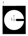
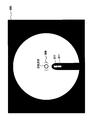
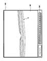
- the pair of split bright lines 311 are presented side by side in the vertical direction.
- the examiner operates the focusing handle to move the focusing lens 124 and the focusing optical system in order to perform focus adjustment. Accordingly, the upper and lower split bright lines 311 move in the left-right direction.
- the examiner performs focusing by operating the focusing handle so that the upper and lower split bright lines 311 are positioned on a straight line extending vertically.
- Autofocus is performed, for example, by specifying the display position of each split bright line 311 and determining the moving direction and moving distance of the focusing lens 124 and the like so that the upper and lower split bright lines 311 are positioned on a straight line.
- the display position of each split bright line 311 can be determined by, for example, obtaining the barycentric position from the luminance distribution of each split bright line 311.
- the moving direction and moving distance are, for example, preset unit moving distances (for example, how much the focusing lens 124 is moved in which direction and how much the split bright line 311 moves in which direction and how much in advance. It is possible to determine with reference to the measurement result).
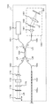
- the OCT unit 150 includes an optical system similar to that of a conventional Fourier domain type optical image measurement device. That is, the OCT unit 150 divides low-coherence light into reference light and signal light, and generates interference light by causing the signal light passing through the fundus of the eye to be examined and the reference light passing through the reference object to generate interference light. An optical system for detecting light and generating a detection signal is provided. This detection signal is sent to the arithmetic and control unit 200.
- the low coherence light source 160 is a broadband light source that outputs a broadband low coherence light L0.
- a broadband light source for example, a super luminescent diode (SLD), a light emitting diode (LED), or the like can be used.
- SLD super luminescent diode
- LED light emitting diode
- the low coherence light L0 includes, for example, light having a wavelength in the near infrared region, and has a temporal coherence length of about several tens of micrometers.
- the low coherence light L0 includes a wavelength longer than the illumination light (wavelength of about 400 nm to 800 nm) of the fundus camera unit 1A, for example, a wavelength in the range of about 800 nm to 900 nm.
- the low coherence light L0 output from the low coherence light source 160 is guided to the optical coupler 162 through the optical fiber 161.
- the optical fiber 161 is configured by, for example, a single mode fiber, a PM fiber (Polarization maintaining fiber), or the like.
- the optical coupler 162 splits the low coherence light L0 into the reference light LR and the signal light LS.
- the optical coupler 162 has both functions of a means for splitting light (splitter) and a means for superposing light (coupler), but here it is conventionally referred to as an “optical coupler”.
- the reference light LR generated by the optical coupler 162 is guided by an optical fiber 163 made of a single mode fiber or the like and emitted from the end face of the fiber. Further, the reference light LR is converted into a parallel light beam by the collimator lens 171 and is reflected by the reference mirror 174 via the glass block 172, the polarizing plate ( ⁇ / 4 plate) 175 and the density filter 173.
- the reference mirror 174 is an example of the “reference object” in the present invention.
- the reference light LR reflected by the reference mirror 174 passes through the density filter 173, the polarizing plate 175, and the glass block 172 again, is condensed on the fiber end surface of the optical fiber 163 by the collimator lens 171, and passes through the optical fiber 163 to the optical coupler 162. Led to.
- the glass block 172 and the density filter 173 act as delay means for matching the optical path lengths (optical distances) of the reference light LR and the signal light LS. Further, the glass block 172 and the density filter 173 function as dispersion compensation means for matching the dispersion characteristics of the reference light LR and the signal light LS.
- the density filter 173 acts as a neutral density filter that reduces the amount of the reference light LR.
- the density filter 173 is configured by, for example, a rotary ND (Neutral Density) filter.
- the density filter 173 is rotationally driven by a drive mechanism (not shown) to change the amount of the reference light LR that contributes to the generation of the interference light LC.
- the polarizing plate 175 is used to correct the optical path length of the reference light LR and is used to improve the image quality of the OCT image.
- the polarizing plate 175 is disposed so as to be inclined by, for example, about 3 degrees with respect to the direction orthogonal to the optical path direction of the reference light LR.
- the polarizing plate 175 is rotationally driven by a predetermined driving mechanism, thereby adjusting the image quality of the interference image.
- the reference mirror 174 is moved in the traveling direction of the reference light LR (in the direction of the double-sided arrow shown in FIG. 3) by a predetermined driving mechanism. Thereby, the optical path length of the reference light LR can be ensured according to the axial length of the eye E and the working distance (distance between the objective lens 113 and the eye E).
- the signal light LS generated by the optical coupler 162 is guided to the end of the connection line 152 by an optical fiber 164 made of a single mode fiber or the like.
- the optical fiber 164 and the optical fiber 152a may be formed from a single optical fiber, or may be formed integrally by joining the respective end faces.
- the signal light LS is guided by the optical fiber 152a and guided to the fundus camera unit 1A. Further, the signal light LS includes the lens 142, the scanning unit 141, the dichroic mirror 134, the photographing lens 126, the relay lens 125, the half mirror 190, the focusing lens 124, the photographing aperture 121, the hole 112a of the aperture mirror 112, the objective lens.
- the eye E is irradiated to the eye E via 113 and irradiated to the fundus Ef.
- the barrier filters 122 and 123 are retracted from the optical path in advance.
- the signal light LS incident on the eye E is imaged and reflected on the fundus oculi Ef.
- the signal light LS is not only reflected by the surface of the fundus oculi Ef, but also reaches the deep region of the fundus oculi Ef and is scattered at the refractive index boundary. Therefore, the signal light LS passing through the fundus oculi Ef includes information reflecting the surface form of the fundus oculi Ef and information reflecting the state of backscattering at the refractive index boundary of the deep tissue of the fundus oculi Ef. This light may be simply referred to as “fundus reflected light of the signal light LS”.
- the fundus reflection light of the signal light LS is guided in the reverse direction along the same path as the signal light LS toward the eye E to be collected on the end surface of the optical fiber 152a. Further, the fundus reflection light of the signal light LS enters the OCT unit 150 through the optical fiber 152 a and returns to the optical coupler 162 through the optical fiber 164.
- the optical coupler 162 superimposes the signal light LS returned via the fundus oculi Ef and the reference light LR reflected by the reference mirror 174 to generate interference light LC.
- the interference light LC is guided to the spectrometer 180 through an optical fiber 165 made of a single mode fiber or the like.
- a spectrometer (spectrometer) 180 detects a spectral component of the interference light LC.
- the spectrometer 180 includes a collimator lens 181, a diffraction grating 182, an imaging lens 183, and a CCD 184.
- the diffraction grating 182 may be transmissive or reflective. Further, in place of the CCD 184, other light detection elements (line sensor or area sensor) such as CMOS may be used.
- the interference light LC incident on the spectrometer 180 is converted into a parallel light beam by the collimator lens 181 and split (spectral decomposition) by the diffraction grating 182.
- the split interference light LC is imaged on the imaging surface of the CCD 184 by the imaging lens 183.
- the CCD 184 detects each spectral component of the separated interference light LC and converts it into electric charges.
- the CCD 184 accumulates this electric charge and generates a detection signal. Further, the CCD 184 sends this detection signal to the arithmetic and control unit 200.
- a Michelson interferometer is used.
- any type of interferometer such as a Mach-Zehnder type can be appropriately used.
- the configuration of the arithmetic and control unit 200 will be described.
- the arithmetic and control unit 200 analyzes the detection signal input from the CCD 184 and forms an OCT image of the fundus oculi Ef.
- the arithmetic processing for this is the same as that of a conventional Fourier domain type optical image measurement device.
- the arithmetic and control unit 200 controls each part of the fundus camera unit 1A and the OCT unit 150.
- the arithmetic control device 200 controls the output of illumination light by the observation light source 101 and the imaging light source 103, and controls the insertion / retraction operation of the exciter filters 105 and 106 and the barrier filters 122 and 123 on the optical path.
- Operation control of display device such as LCD 140, movement control of illumination diaphragm 110 (control of aperture value), control of aperture value of photographing diaphragm 121, movement control of focusing lens 124 (focus adjustment, magnification adjustment), focusing optics
- the system and alignment optical system 190A are controlled.
- the arithmetic and control unit 200 controls the scanning unit 141 to scan the signal light LS.
- the arithmetic and control unit 200 controls the output of the low coherence light L0 by the low coherence light source 160, the movement control of the reference mirror 174, and the rotation operation of the density filter 173 (the amount of decrease in the light amount of the reference light LR). Control), charge accumulation time by CCD 184, charge accumulation timing, signal transmission timing, and the like.
- the arithmetic and control unit 200 includes a microprocessor, a RAM, a ROM, a hard disk drive, a keyboard, a mouse, a display, a communication interface, and the like, like a conventional computer.
- the hard disk drive stores a computer program for controlling the optical image measurement device 1.
- the arithmetic and control unit 200 may include a dedicated circuit board that forms an OCT image based on a detection signal from the CCD 184.
- Control system The configuration of the control system of the optical image measurement device 1 will be described with reference to FIG. 5, the imaging devices 10 and 12 are described separately from the fundus camera unit 1A, and the CCD 184 is described separately from the OCT unit 150. However, as described above, the imaging devices 10 and 12 are included in the fundus oculi. Mounted on the camera unit 1 ⁇ / b> A, the CCD 184 is mounted on the OCT unit 150.
- the control system of the optical image measurement device 1 is configured around the control unit 210 of the arithmetic and control device 200.
- the control unit 210 includes, for example, the aforementioned microprocessor, RAM, ROM, hard disk drive, communication interface, and the like.
- the control unit 210 is an example of the “control unit” in the present invention.
- the control unit 210 is provided with a main control unit 211 and a storage unit 212.
- the main control unit 211 controls each part of the fundus camera unit 1 ⁇ / b> A, the OCT unit 150, and the arithmetic control device 200.
- the storage unit 212 stores various data. Examples of data stored in the storage unit 212 include image data of an OCT image, image data of a fundus oculi image Ef ′, and eye information to be examined.
- the eye information includes, for example, various information related to the eye such as information about the subject such as patient ID and name, left eye / right eye identification information, and diagnosis / test results of the eye.
- the main control unit 211 performs a process of writing data to the storage unit 212 and a process of reading data from the storage unit 212.
- the storage unit 212 stores data of unit movement distance (described above) in alignment adjustment and focus adjustment. Further, the storage unit 212 stores a computer program for executing an operation (flow chart) described later. The main control unit 211 operates based on the data and the computer program.
- the image forming unit 220 forms tomographic image data of the fundus oculi Ef based on the detection signal from the CCD 184.
- This image data forming process includes processes such as noise removal (noise reduction), filter processing, and FFT (Fast Fourier Transform), as in the conventional Fourier domain type OCT technique.
- the image forming unit 220 includes, for example, the above-described circuit board and communication interface.
- the image forming unit 220 is an example of the “image forming unit” in the present invention.
- image data and “image” displayed based on the “image data” may be identified.
- the image processing unit 230 performs various types of image processing and analysis processing on the fundus image (captured image of the fundus surface) acquired by the fundus camera unit 1A and the tomographic image formed by the image forming unit 220. For example, the image processing unit 230 executes various correction processes such as image brightness correction and dispersion correction.
- the image processing unit 230 forms image data of a three-dimensional image of the fundus oculi Ef by executing interpolation processing for interpolating pixels between tomographic images formed by the image forming unit 220.
- the image data of a three-dimensional image means image data in which pixel positions are defined by a three-dimensional coordinate system.
- image data of a three-dimensional image there is image data composed of voxels arranged three-dimensionally. This image data is called volume data or voxel data.
- the image processing unit 230 When displaying an image based on the volume data, the image processing unit 230 performs rendering processing (volume rendering, MIP (Maximum Intensity Projection), etc.) on the volume data, and views the image from a specific line-of-sight direction.
- rendering processing volume rendering, MIP (Maximum Intensity Projection), etc.
- MIP Maximum Intensity Projection
- the stack data is image data obtained by three-dimensionally arranging a plurality of tomographic images obtained along a plurality of scanning lines based on the positional relationship of the scanning lines. That is, the stack data is image data obtained by expressing a plurality of tomographic images originally defined by individual two-dimensional coordinate systems using one three-dimensional coordinate system (that is, embedding in one three-dimensional space). is there.
- the image processing unit 230 can also perform various image processing and analysis processing on the three-dimensional image.
- the image processing unit 230 includes an alignment determination unit 231, an in-focus determination unit 232, an image position determination unit 233, an image quality determination unit 234, and a tracking determination unit 235.
- Each of the determination units 231 to 235 constitutes a part of “determination means” of the present invention.
- the alignment determination unit 231 determines whether the position of the optical system is appropriate, that is, whether the optical system is positioned at an appropriate position with respect to the eye E at a predetermined timing after the alignment adjustment of the optical system. As described above, the alignment determination unit 231 determines the suitability of the alignment state at a predetermined timing after alignment adjustment. Even after the alignment adjustment, the alignment state may change due to the eye movement of the eye E, the movement of the subject, and the like, so such alignment determination is effective.
- the alignment determination unit 231 analyzes the fundus image of the eye E acquired in a state where the alignment bright spot 310 is projected after the alignment adjustment (see FIG. 4).
- the position of the alignment scale 309 in the fundus image frame is known (constant).
- the alignment determination unit 231 specifies the positions (center of gravity positions, etc.) of the pair of alignment bright spots 310 in the manner described above. Subsequently, the alignment determination unit 231 determines whether or not these specific positions are within a predetermined allowable range, that is, within the alignment scale 309 (parenthesis-shaped image). When it is determined that these specific positions are within the allowable range, the alignment determination unit 231 determines that the alignment state is appropriate. On the other hand, when these specific positions are not within the allowable range, the alignment determination unit 231 determines that the alignment state is not appropriate.
- a specific example of processing for determining the suitability of the alignment state is described in, for example, Japanese Patent Application No. 2008-13989 by the present applicant.
- the focus determination unit 232 determines whether or not the focus state is appropriate, that is, whether or not the fundus oculi Ef is properly focused (whether or not the focus is in focus) at a predetermined timing after focus adjustment. . Even after the focus adjustment, the alignment state is effective because the focus state may change due to the eye movement of the eye E or the movement of the subject.
- the in-focus determination unit 232 analyzes the fundus image of the eye E acquired with the split bright line 311 projected after focus adjustment (see FIG. 4).
- the focus determination unit 232 specifies the position (center of gravity position) of the upper and lower split bright lines 311 in the left-right direction in the manner described above. Subsequently, the focus determination unit 232 determines whether these specific positions are within an allowable range in the left-right direction. This allowable range is set in advance. Thereby, it is determined whether or not the upper and lower split bright lines 311 are arranged on a substantially straight line. When it is determined that these specific positions are within the allowable range, the focus determination unit 232 determines that the focus state is appropriate. On the other hand, when these specific positions are not within the allowable range, the focus determination unit 232 determines that the focus state is not appropriate.
- a specific example of the process for determining the suitability of the focus state is described in, for example, Japanese Patent Application No. 2008-13989 by the present applicant.
- the image position determination unit 233 determines whether the position of the tomographic image of the fundus oculi Ef within the frame is appropriate. In particular, the image position determination unit 233 determines whether or not the depth position (position in the z direction) of the tomographic image in the frame is appropriate.
- the image position determination unit 233 specifies the position in the z direction within the frame of the image corresponding to the fundus surface. A specific example of this process will be described.
- the tomographic image is composed of a plurality of one-dimensional images extending in the depth direction. These one-dimensional images are arranged along the scanning line of the signal light LS.
- the frame of the tomographic image is black (luminance value 0), and the pixel corresponding to the fundus tissue (layer) has a luminance value corresponding to the intensity of the reflected light at that site. A portion having a depth that does not reach the signal light LS is expressed in black. That is, the tomographic image is an image in which various layers of the fundus are expressed in gray scale in a black frame.
- the tomographic image may be a pseudo color image corresponding to the luminance value.
- the image position determination unit 233 specifies a pixel corresponding to the fundus surface based on the luminance value of the pixel constituting each one-dimensional image. Thereby, the pixel group arranged along the scanning direction of the signal light LS is specified. This pixel group is an image area corresponding to the fundus surface.
- the specific target is not limited to the fundus surface, and may be a high-luminance part such as IS / OS.
- the image position determination unit 233 determines whether the specified pixel group is within an allowable range in the z direction. This allowable range is set in advance. When the pixel group is within the allowable range, the image position determination unit 233 determines that the depth position of the tomographic image in the frame is appropriate. On the other hand, when the pixel group is not within the allowable range, the image position determination unit 233 determines that the depth position of the tomographic image in the frame is not appropriate.
- the upper end region (image region corresponding to the fundus surface) and the lower end region (image region corresponding to the latest arrival depth of the signal light LS) of the tomographic image are included in the frame, that is, the upper end region and the lower end region are included.
- the position of the tomographic image may be determined so as not to be cut off from the frame. For this purpose, for example, in each one-dimensional image, it is determined whether or not the luminance values of the upper and lower vicinity regions of the frame are 0, and further whether or not there is a pixel group whose luminance value is not 0. What should I do?
- the image quality determination unit 234 analyzes the tomographic image of the fundus oculi Ef and determines whether the image quality of the tomographic image is appropriate. There are various image quality evaluation methods. An example will be described below.
- the image quality determination unit 234 specifies the pixel with the maximum luminance and the pixel with the minimum luminance for each one-dimensional image in the depth direction constituting the tomographic image.
- the image quality determination unit 234 creates a luminance value histogram (for example, 8 bits) based on the luminance value of a predetermined range of pixel groups (for example, 40 pixels before and after) including each identified pixel.
- the image quality determination unit 234 searches for the maximum position (luminance value) where the frequency value exceeds 0 in the histogram corresponding to the pixel group including the pixel having the minimum luminance. Further, in the histogram corresponding to the pixel group including the pixel having the maximum luminance, the total number of pixels (N) included in the range equal to or less than the luminance value searched above and the 255th luminance value from the top above the searched luminance value. And the total number of pixels (S) included in.
- the image quality determination unit 234 evaluates the percentage of the portion that can be regarded as a signal (that is, the portion that can be regarded as not noise) in the tomographic image by the following arithmetic expression: 100 ⁇ S ⁇ (S + N) . Such calculation processing is executed for each one-dimensional image, and an average value of these calculation results is used as an evaluation value of image quality.
- the image quality determination unit 234 determines whether the evaluation value thus obtained is equal to or greater than a predetermined threshold value. This threshold is set in advance. When it is determined that the evaluation value is equal to or greater than the threshold value, the image quality determination unit 234 determines that the image quality is appropriate. On the other hand, when it is determined that the evaluation value is less than the threshold value, the image quality determination unit 234 determines that the image quality is not appropriate.
- the tracking determination unit 235 determines whether or not the tracking state is appropriate when tracking (following) the irradiation position of the signal light LS with respect to the attention area (OCT image acquisition target area) of the fundus oculi Ef. That is, the tracking determination unit 235 determines whether or not tracking of the irradiation position of the signal light LS is appropriately executed for the eye movement of the eye E or the like.
- the tracking can be executed by controlling the galvanometer mirror in the scanning unit 141.
- the position of the fundus characteristic part (optic nerve head, etc.) in each frame of the moving image is specified, and this specified position is always the same position (frame center region, etc.)
- the irradiation position of the signal light LS is controlled so as to be disposed at the position.
- a predetermined scanning pattern for example, a cross scan
- a feature shape for example, a concave shape of a macular depicted by a pair of sequentially obtained tomographic images.
- the irradiation position of the signal light LS is controlled so that the feature points (for example, the macular center) are always arranged at the same position (frame center region or the like).
- tracking based on an OCT image is desirable because tracking by a fundus image may be insufficient.
- the target site for OCT measurement is set by selecting an internal fixation target (macular, optic nerve head, etc.).
- the tracking determination unit 235 determines whether or not the tracking state is appropriate by determining whether or not the tracking target part is included in the scanning region of the signal light LS.
- the scanning area is set to a predetermined area (such as a 6 mm ⁇ 6 mm square area) centered on the optical axis of the photographing optical system 120, for example. Further, the position of the tracking target part can be obtained with high accuracy by tracking using the above-described OCT image, for example.
- the signal light LS is applied to the eye E along the same optical axis (optical axis of the imaging optical system 120) as illumination light for fundus photography, and the fundus reflection light is also guided along the optical axis.
- the frame center of the fundus image coincides with the center position of the scanning region.
- the image processing unit 230 having the above configuration includes, for example, a microprocessor, a RAM, a ROM, a hard disk drive, and the like. Further, a circuit board that specializes in predetermined image processing and analysis processing may be included.
- the display unit 240 includes the touch panel monitor 11. Furthermore, a display of the arithmetic and control unit 200 may be included in the display unit 240.
- the display unit 240 is an example of the “display unit” in the present invention.
- the operation unit 250 includes an input device and an operation device such as a keyboard and a mouse. In addition, the operation unit 250 includes various input devices and operation devices provided on the surface of the casing of the optical image measurement device 1 or on the outside.
- the display unit 240 and the operation unit 250 need not be configured as individual devices.
- a device in which the display unit 240 and the operation unit 250 are integrated, such as a touch panel LCD, can be used.
- the scanning mode of the signal light LS by the optical image measuring device 1 includes, for example, horizontal scanning, vertical scanning, cross scanning, radiation scanning, circular scanning, concentric scanning, and helical scanning. These scanning modes are selectively used as appropriate in consideration of the observation site of the fundus, the analysis target (such as retinal thickness), the time required for scanning, the precision of scanning, and the like.
- the horizontal scan is to scan the signal light LS in the horizontal direction (x direction).
- the horizontal scan also includes an aspect in which the signal light LS is scanned along a plurality of horizontal scanning lines arranged in the vertical direction (y direction). In this aspect, it is possible to arbitrarily set the scanning line interval. By sufficiently narrowing the interval between the scanning lines, the above-described three-dimensional image can be formed (three-dimensional scan). The same applies to the vertical scan.
- the cross scan scans the signal light LS along a cross-shaped trajectory composed of two linear trajectories (straight trajectories) orthogonal to each other.
- the signal light LS is scanned along a radial trajectory composed of a plurality of linear trajectories arranged at a predetermined angle.
- the cross scan is an example of a radiation scan.
- the circle scan scans the signal light LS along a circular locus.
- the signal light LS is scanned along a plurality of circular trajectories arranged concentrically around a predetermined center position.
- a circle scan is considered a special case of a concentric scan.
- the spiral scan scans the signal light LS along a spiral trajectory.
- the scanning unit 141 can scan the signal light LS independently in the x direction and the y direction, respectively, by the configuration as described above. Therefore, the scanning unit 141 can scan the signal light LS along an arbitrary locus on the xy plane. . Thereby, various scanning modes as described above can be realized.
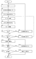
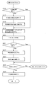
- FIGS. 6 and 7 represent an example of the operation of the optical image measurement device 1.
- 8 to 15 show examples of display screens.
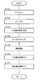
- the control unit 210 displays a predetermined display screen (for example, the display screen 290 shown in FIG. 8) on the display unit 240 (touch panel monitor 11) in response to a predetermined operation (for example, power-on operation) (S2).
- the display screen 290 includes an adjustment screen 300 and an interference image display screen 400.
- the adjustment screen 300 is the same as that shown in FIG. 4 and is used for alignment adjustment and focus adjustment. Although illustration is omitted, an image captured by the fundus camera unit 1A is displayed on the adjustment screen 300. In FIGS. 8 to 12 and 15, information unnecessary for the following explanation is omitted from the information shown in FIG. 4.
- an interference image is displayed on the interference image display screen 400 (described later), the display state at this stage is, for example, a “sandstorm” state.
- the examiner operates the operation unit 250 to turn on the observation light source 101. Thereby, the anterior segment image of the eye E is displayed on the adjustment screen 300.
- the examiner operates the operation unit 250 (control lever) to move the fundus camera unit 1A to the subject side. At this time, the display image on the adjustment screen 300 is switched to a fundus observation image.
- the control unit 210 turns on the alignment light source 190a in response to a predetermined operation. Thereby, the alignment bright spot is projected onto the eye E, and the alignment bright spot 310 is displayed on the adjustment screen 300 as shown in FIG. 9 (S3). At this stage, since the alignment state is generally inappropriate, two alignment bright spots 310 are displayed outside the alignment scale 309.
- the examiner operates the control lever to adjust the position of the fundus camera unit 1A so as to move the two alignment bright spots 310 to the inside of the alignment scale 309 (S4).
- FIG. 10 shows an adjustment screen 300 in a state where the alignment adjustment is completed. Instead of manually adjusting the alignment as described above, it is also possible to execute auto alignment as described above.
- the control unit 210 turns on the LED 109a. Thereby, the split bright line is projected onto the eye E, and the split bright line 311 is displayed on the adjustment screen 300 as shown in FIG. 11 (S5). At this stage, since the focus state is generally inappropriate, the upper and lower split bright lines 311 are not aligned.
- the controller 210 performs autofocus in the manner described above (S6).
- the focus determination unit 232 determines whether or not the focus state by the autofocus is appropriate (S7).
- the control unit 210 causes the display unit 240 to display predetermined warning information (S8).
- This warning information informs, for example, that the autofocus has failed or that the examination is urged again.
- the warning information may be character string information or image information.
- An example of string information is the following message: "Autofocus failed. Pull the control lever again and try again.” The examiner who recognizes the failure of the autofocus from the warning information starts the examination again from the beginning. If “No” in step 7 occurs a predetermined number of times, the inspection may be terminated.
- the alignment determination unit 231 determines the suitability of the alignment state based on the position of the alignment bright spot 310 at this stage (S9).
- the control unit 210 causes the display unit 240 to display predetermined warning information (S10).
- This warning information informs, for example, that the alignment has been shifted or that the alignment is urged again.
- the warning information may be character string information or image information.
- An example of string information is the following message: “Match the alignment bright spots and put them in the scale.” The examiner who recognizes that the alignment state is not appropriate based on the warning information returns to step 4 and performs the alignment again.
- “No” in step 9 occurs a predetermined number of times, the inspection may be terminated or the inspection may be restarted from the beginning.
- the control unit 210 controls the OCT unit 150, the scanning unit 141, and the image forming unit 220 to automatically perform an interference image (tomographic image) of the fundus oculi Ef. Detection is performed (S11). Automatic detection can be performed by analyzing a detection signal obtained while moving the reference mirror 174, for example. Alternatively, automatic detection may be performed by actually forming an interference image and analyzing the luminance value of the interference image.
- the control unit 210 causes the display unit 240 to display predetermined warning information (S13).
- This warning information informs, for example, that no interference image is detected or that automatic detection is urged again.
- the warning information may be character string information or image information.
- An example of character string information is the following message: “Automatic interference image detection failed. Please try again.”
- the examiner who has recognized that the automatic detection has failed due to the warning information performs a predetermined operation (for example, touching the screen of the touch panel monitor 11) and instructs the automatic detection of the interference image again.
- “No” in step 12 occurs a predetermined number of times, the inspection may be terminated or the inspection may be restarted from the beginning.
- an interference image of the fundus oculi Ef is drawn somewhere in the frame.
- the interference image is displayed on the image display unit 401 of the interference image display screen 400.
- the interference image at this stage is displayed at a position where a part thereof protrudes from the interference image display screen 400 as shown in FIG.
- the image quality determination unit 234 determines whether or not the image quality of the detected interference image is appropriate (S14). When it is determined that the image quality is not appropriate (S14: No), the control unit 210 controls the rotation of the polarizing plate 175 to increase the image quality level (S15). At this time, it is desirable to control the polarizing plate 175 so that the image quality level is maximized.
- the image quality display unit 402 is an indicator that presents an evaluation value of image quality. Note that the evaluation value may be displayed as it is.
- the image position determination unit 233 determines whether the position of the interference image in the frame is appropriate (S16).
- the position of the interference image G is not appropriate. Determined. At this time, warning information indicating that may be displayed.
- the examiner designates a desirable display position of the interference image G within the frame (S17). This operation is performed, for example, by touching a desired position on the image display unit 401 (touch panel monitor 11). A preset position (for example, the center position of the image display unit 401) may be automatically designated.
- the control unit 210 obtains the displacement between the actual position of the interference image G (for example, the position of the macular center) and the designated position. Then, the control unit 210 controls the reference mirror 174 and the scanning unit 141 so as to cancel this displacement, that is, so that the interference image G is displayed at the designated position. Thereby, as shown in FIG. 14, the interference image G is displayed at a suitable position in the frame (S18).
- the displacement of the interference image G in the z direction can be canceled by adjusting the position of the reference mirror 174. Further, the displacement of the interference image G in the x direction and the y direction can be canceled by adjusting the scanning position of the signal light LS by the scanning unit 141.
- the control unit 210 displays the scanning region image 314 and the tracking region image 315 so as to overlap the fundus observation image (S19). Then, the control unit 210 controls the scanning unit 141 and the like to start tracking (S20).
- the scanning region image 314 represents a region in which the signal light LS is scanned, and is displayed according to a mode designated in advance.
- a scanning region image 314 shown in FIG. 15 corresponds to the above-described three-dimensional scan.
- the tracking area image 315 represents a characteristic part of the fundus oculi Ef to be tracked, and moves on the adjustment screen according to the tracking situation. Tracking is performed so that the tracking area image 315 is positioned at the center of the scanning area image 314.
- the tracking determination unit 235 determines whether the tracking state is appropriate (S21). This processing is performed by determining whether or not the tracking area image 315 is included in the scanning area image 314, for example. Note that it may be determined whether the tracking area image 315 is included in a predetermined area (area near the center) in the scanning area image 314.
- the control unit 210 causes the display unit 240 to display predetermined warning information (S22).
- This warning information informs that tracking cannot be suitably performed, for example.
- the warning information may be character string information or image information.
- An example of string information is the following message: “Tracking position is out of scanable range”.
- the examiner who recognizes that the tracking state is not appropriate based on the warning information operates the operation unit 250 (for example, a fixation position adjustment key), and fixes the eye E to be examined so that the tracking area image 315 enters the scanning area image 314.
- the viewing position is adjusted (S23).
- the tracking determination unit 235 determines whether the tracking state is appropriate.
- the image processing unit 230 When it is determined that the tracking state is appropriate (S21: Yes), or when the fixation position adjustment is completed (S23), the image processing unit 230 performs the alignment state, the focus state, and the position of the interference image in the frame. And the suitability of the image quality of the interference image is determined (S24).
- control unit 210 controls the OCT unit 150, the scanning unit 141, and the image forming unit 220 to form an interference image of the scanning region (S25). ).
- the control unit 210 controls the OCT unit 150, the scanning unit 141, and the image forming unit 220 to form an interference image of the scanning region (S25). ).
- a message indicating that measurement is possible may be displayed. In this case, the examiner who has seen the message presses the photographing switch to start measurement.
- the control unit 210 controls the fundus camera unit 1A to perform color photographing of the fundus oculi Ef.
- the acquired interference image and color fundus image are stored in the storage unit 212. This completes the inspection.
- the optical image measurement device 1 has a function of acquiring a tomographic image and a fundus image of the fundus (object to be measured).
- the fundus image is a two-dimensional image of the fundus on a plane substantially orthogonal to the traveling direction of the signal light LS with respect to the fundus.
- the optical image measurement device 1 has an alignment function, a focus function, and a tracking function.
- the alignment function is realized by alignment means including the alignment optical system 190A.
- the focus function is realized by focusing means including a focusing optical system.
- the tracking function is realized by tracking means including the control unit 210. The tracking can be performed based on a tomographic image or can be performed based on a fundus image.
- the configuration for acquiring a fundus image (configuration as a fundus camera) is an example of the “imaging unit” of the present invention.
- the optical image measurement device 1 determines whether each of the alignment state, the focus state, the position of the tomographic image in the frame, the image quality of the tomographic image, and the tracking state is appropriate, and it is determined that all these conditions are appropriate.
- the final tomographic image can be acquired. Note that the tomographic image used for determining the suitability of the conditions is acquired in advance, and it is desirable to use a simple scanning mode of the signal light LS (cross scanning in the above embodiment). Further, the distribution of scanning points (irradiation positions of the signal light LS) may not be so dense. On the other hand, the final tomographic image is a precise one used for diagnosis and the like, and it is desirable that the distribution of scanning points is dense (for example, a distribution that can generate a three-dimensional image).
- the above various conditions are automatically measured at an appropriate timing, so that the measurement timing is not missed.
- the optical image measurement device 1 can display warning information when any of the various conditions described above is not appropriate. Thereby, the examiner can recognize that the condition is not appropriate, and can take measures to make the condition appropriate.
- the suitability of each of the alignment state, focus state, tomographic image position in the frame, tomographic image quality, and tracking state is determined. This determination can be omitted.
- the optical image measurement device determines whether each of the alignment state, the focus state, and the position of the tomographic image in the frame is appropriate, and when all these conditions are determined to be appropriate, the final tomographic image is determined. Allows acquisition of images. Further, similarly to the above-described embodiment, it is possible to automatically perform measurement for obtaining a final tomographic image when it is determined that all conditions are appropriate.
- the essential condition determination process it may be configured to perform a tomographic image quality determination process or a tracking state determination process. These incidental conditions can be added as appropriate in consideration of the type (dynamics) of the object to be measured.
- It can be configured to prohibit the acquisition of a tomographic image of an object to be measured when it is determined that any of the above various conditions is not appropriate.
- the control unit 210 does not accept this instruction (ignore). Can be configured.
- the position of the reference mirror 174 is changed to change the optical path length difference between the optical path of the signal light LS and the optical path of the reference light LR.
- the method of changing the optical path length difference is limited to this. Is not to be done.
- the optical path length difference can be changed by moving the fundus camera unit 1A and the OCT unit 150 integrally with the eye E to change the optical path length of the signal light LS.
- the optical path length difference can be changed by moving the measured object in the depth direction (z direction).
- the computer program in the above embodiment can be stored in any recording medium that can be read by the drive device of the computer.
- this recording medium for example, an optical disk, a magneto-optical disk (CD-ROM / DVD-RAM / DVD-ROM / MO, etc.), a magnetic storage medium (hard disk / floppy (registered trademark) disk / ZIP, etc.), etc. are used. Is possible. It can also be stored in a storage device such as a hard disk drive or memory. Furthermore, this program can be transmitted and received through a network such as the Internet or a LAN.
Landscapes
- Physics & Mathematics (AREA)
- General Physics & Mathematics (AREA)
- Health & Medical Sciences (AREA)
- Engineering & Computer Science (AREA)
- General Health & Medical Sciences (AREA)
- Life Sciences & Earth Sciences (AREA)
- Nuclear Medicine, Radiotherapy & Molecular Imaging (AREA)
- Radiology & Medical Imaging (AREA)
- Optics & Photonics (AREA)
- Biophysics (AREA)
- Ophthalmology & Optometry (AREA)
- Signal Processing (AREA)
- Immunology (AREA)
- Pathology (AREA)
- Human Computer Interaction (AREA)
- Analytical Chemistry (AREA)
- Automation & Control Theory (AREA)
- Chemical & Material Sciences (AREA)
- Biochemistry (AREA)
- Biomedical Technology (AREA)
- Heart & Thoracic Surgery (AREA)
- Medical Informatics (AREA)
- Molecular Biology (AREA)
- Surgery (AREA)
- Animal Behavior & Ethology (AREA)
- Public Health (AREA)
- Veterinary Medicine (AREA)
- Eye Examination Apparatus (AREA)
- Investigating Or Analysing Materials By Optical Means (AREA)
Abstract
計測タイミングを逃すことなく容易に計測を行える光画像計測装置を提供する。光画像計測装置1の画像処理部230は、被検眼Eに対する光学系のアライメント状態の適否と、眼底Efの注目領域に対するフォーカス状態の適否と、予備的に取得された断層像のフレーム内における位置の適否と、予備的に取得された断層像の画質の適否と、被測定物体の動きに対する信号光LSの照射位置のトラッキング状態の適否をそれぞれ判定する。これら全ての条件が適正であると判定されたときに、制御部210は、光学系及び画像形成部220を制御して眼底Efの注目領域の断層像を形成させる。それにより、生体眼のように動きのある被測定物体の断層像を取得する場合であっても、計測タイミングを逃すことなく容易に計測を行うことが可能となる。
Description
この発明は、光ビームを用いて被測定物体の表面形態や内部形態を表す画像を形成する光画像計測装置に関する。
近年、レーザ光源等からの光ビームを用いて被測定物体の表面形態や内部形態を表す画像を形成する光画像計測技術が注目を集めている。光画像計測技術は、X線CT装置のような人体に対する侵襲性を持たないことから、医療分野や生物学分野における応用の展開が特に期待されている。
特許文献1には、光画像計測技術を適用した装置が開示されている。この装置は、測定腕が回転式転向鏡(ガルバノミラー)により物体を走査し、参照腕に参照ミラーが設置されており、その出口に計測腕及び参照腕からの光束の干渉光の強度を分光器で分析する干渉器が設けられている。更に、参照腕は、参照光光束位相を不連続な値で段階的に変えるように構成されている。
特許文献1の装置は、いわゆる「フーリエドメインOCT(Fourier Domain Optical Coherence Tomography)」の手法を用いるものである。すなわち、被測定物体に対して低コヒーレンス光のビームを照射し、その反射光と参照光とを重ね合わせて干渉光を生成し、この干渉光のスペクトル強度分布を取得してフーリエ変換を施すことにより被測定物体の深度方向(z方向)の形態を画像化するものである。
更に、特許文献1に記載の装置は、光ビーム(信号光)を走査するガルバノミラーを備え、それにより被測定物体の所望の測定対象領域の画像を形成するようになっている。この装置においては、z方向に直交する1方向(x方向)にのみ光ビームを走査するように構成されているので、この装置により形成される画像は、光ビームの走査方向(x方向)に沿った深度方向(z方向)の2次元断層像となる。
特許文献2には、信号光を水平方向及び垂直方向に走査することにより水平方向の2次元断層像を複数形成し、これら複数の断層像に基づいて測定範囲の3次元の断層情報を取得して画像化する技術が開示されている。この3次元画像化としては、たとえば、複数の断層像を垂直方向に並べて表示させる方法や(スタックデータなどと呼ばれる)、複数の断層像にレンダリング処理を施して3次元画像を形成する方法などが考えられる。
特許文献3、4には、他のタイプの光画像計測装置が開示されている。特許文献3には、被測定物体に照射される光の波長を走査し、各波長の光の反射光と参照光とを重ね合わせて得られる干渉光に基づいてスペクトル強度分布を取得し、それに対してフーリエ変換を施すことにより被測定物体の形態を画像化する光画像計測装置が記載されている。このような光画像計測装置は、スウェプトソース(Swept Source)タイプなどと呼ばれる。
また、特許文献4には、所定のビーム径を有する光を被測定物体に照射し、その反射光と参照光とを重ね合わせて得られる干渉光の成分を解析することにより、光の進行方向に直交する断面における形態を表す画像を形成する光画像計測装置が記載されている。このような光画像計測装置は、フルフィールド(full-field)タイプ、或いはエンフェイス(en-face)タイプなどと呼ばれる。
特許文献5には、OCT技術を眼科分野に適用した構成が開示されている。なお、光画像計測装置が眼科分野に応用される以前には、眼底カメラ等の眼科撮影装置が利用されていた(たとえば特許文献6を参照)。
OCT技術を用いた眼底撮影装置は、眼底表面を撮影する眼底カメラと比較して、眼底の様々な深度の画像を選択的に取得できるという利点がある。また、眼底カメラよりも高詳細の画像を取得できるという利点もある。このようなOCT技術を用いることにより、診断の精度の向上や病変の早期発見への寄与が期待されている。
従来の光画像計測装置は、図16に示すような手順で撮影を行うのが一般的である。以下、一例として、特許文献5のような装置を使用して眼底検査を行う場合を説明する。まず、コントロールレバーを操作して、被検眼に対する装置光学系のアライメントを行う(S101)。この作業は、たとえば、アライメント光学系により輝点を被検眼に投影し、コントロールレバーを操作して、画面に表示された輝点を括弧型のスケール内に配置させるようにして行う。
次に、被検眼の注目領域(たとえば黄斑部、視神経乳頭など)に対し、装置光学系をフォーカス(合焦)する(S102)。この作業は、たとえば、所定の光学系により合焦用の視標を被検眼に投影し、合焦ハンドルを操作することにより行う。より具体的には、2本の直線状の輝線からなるスプリット輝線を合焦用の視標として投影し、2本の輝線が一直線上に配置されるように合焦ハンドルを操作することにより行う。
フォーカスが完了したら、干渉像の検索・表示を行う(S103)。この作業は、参照光の光路長を調整することにより、眼底の所望の深度位置の干渉像を表示させるものである。その際、所望の深度位置の画質を高めるように光路長を調整する。なお、光路長の調整は、オペレータが手作業で行ってもよいし、干渉像を取得して解析することにより自動で行ってもよい。
続いて、所定のボタンを押下してオートトラッキングを開始する(S104)。オートトラッキングは、注目領域を干渉像のほぼ中央に配置させるように、被検眼の動きに光ビーム(信号光)を追従させる技術である。この技術については、たとえば特許文献7~10に開示されている。
オートトラッキングを実施しつつ、所望のタイミングで、オペレータは、撮影スイッチを押下する(S105)。これを受けて、装置は干渉像を取得し(S106)、更に、眼底像を撮影する(S107)。
上記のような手順で検査を行う場合、アライメント、フォーカス、干渉像の位置調整、画質、及びオートトラッキングの各状態が好適であるかの判断が困難な場合がある。特に、光画像計測装置の使用に熟練していない検者には当該判断は困難であり、計測タイミングを逃すおそれが高い。また、或る程度の熟練者であっても、計測タイミングを逃すおそれが無いとは言えない。
なお、眼底カメラのような従来の眼科撮影装置において、アライメントやフォーカスの状態を判断して自動的に撮影を行う機能を具備するものがあるが、これをそのまま光画像計測装置に適用することは困難である。何故なら、光画像計測装置により得られる画像(干渉像)は眼底像よりも精細であり、また、干渉像は眼底像よりも狭い範囲を対象としているため、従来の技術では精度が不十分になるおそれがあるからである。また、干渉像の位置調整や画質については、従来の技術では対応することができない。
この発明は、このような問題を解決するためになされたもので、その目的は、計測タイミングを逃すことなく容易に計測を行うことが可能な光画像計測装置を提供することにある。
上記目的を達成するために、請求項1に記載の発明は、低コヒーレンス光を信号光と参照光とに分割し、被測定物体を経由した前記信号光と参照物体を経由した前記参照光とを干渉させて干渉光を生成し、前記干渉光を検出して検出信号を生成する光学系と、前記検出信号に基づいて前記被測定物体の断層像を形成する画像形成手段と、を有する光画像計測装置であって、被測定物体に対する前記光学系の位置合わせを行うアライメント手段と、前記被測定物体の注目領域に対する前記光学系の合焦を行う合焦手段と、前記アライメント手段による前記光学系の位置の適否、前記合焦手段による合焦状態の適否、及び、前記画像形成手段により形成される前記注目領域の断層像のフレーム内における位置の適否をそれぞれ判定する判定手段と、前記光学系の位置、前記合焦状態、及び前記フレーム内における位置の全てが適正であると判定されたときに、前記光学系及び前記画像形成手段を制御して前記注目領域の断層像の取得を可能にする制御手段と、を備えることを特徴とする。
また、請求項2に記載の発明は、請求項1に記載の光画像計測装置であって、前記制御手段は、前記光学系の位置、前記合焦状態、及び前記フレーム内における位置のうちの少なくとも1つが不適正であると判定されたときに、前記被測定物体の断層像の取得を禁止する、ことを特徴とする。
また、請求項3に記載の発明は、請求項1に記載の光画像計測装置であって、表示手段を更に備え、前記制御手段は、前記光学系の位置、前記合焦状態、及び前記フレーム内における位置のうちの少なくとも1つが不適正であると判定されたときに、前記表示手段に警告情報を表示させる、ことを特徴とする。
また、請求項4に記載の発明は、請求項1に記載の光画像計測装置であって、前記判定手段は、更に、前記画像形成手段により形成される断層像を解析して当該断層像の画質の適否を判定し、前記制御手段は、前記光学系の位置、前記合焦状態、前記フレーム内における位置、及び前記断層像の画質の全てが適正であると判定されたときに、前記光学系及び前記画像形成手段を制御して前記注目領域の断層像の取得を可能にする、ことを特徴とする。
また、請求項5に記載の発明は、請求項4に記載の光画像計測装置であって、前記制御手段は、前記光学系の位置、前記合焦状態、前記フレーム内における位置、及び前記断層像の画質のうちの少なくとも1つが不適正であると判定されたときに、前記被測定物体の断層像の取得を禁止する、ことを特徴とする。
また、請求項6に記載の発明は、請求項4に記載の光画像計測装置であって、表示手段を更に備え、前記制御手段は、前記光学系の位置、前記合焦状態、前記フレーム内における位置、及び前記断層像の画質のうちの少なくとも1つが不適正であると判定されたときに、前記表示手段に警告情報を表示させる、ことを特徴とする。
また、請求項7に記載の発明は、請求項4に記載の光画像計測装置であって、前記光学系は、前記参照光の光路上に偏光板を備え、前記制御手段は、前記断層像の画質が不適正であると判定されたときに、画質が最大になるように前記偏光板を制御する、ことを特徴とする。
また、請求項8に記載の発明は、請求項1に記載の光画像計測装置であって、前記画像形成手段により形成される断層像に基づいて、前記フレーム内の略中央に前記注目領域の断層像が配置されるように、前記被測定物体に対する前記信号光の照射位置を前記被測定物体の動きに追従させる追従手段と、を更に備え、前記判定手段は、更に、前記信号光の照射位置の追従状態の適否を判定し、前記制御手段は、前記光学系の位置、前記合焦状態、前記フレーム内における位置、及び前記追従状態の全てが適正であると判定されたときに、前記光学系及び前記画像形成手段を制御して前記注目領域の断層像の取得を可能にする、ことを特徴とする。
また、請求項9に記載の発明は、請求項1に記載の光画像計測装置であって、前記被測定物体に対する前記信号光の進行方向に略直交する面における前記被測定物体の2次元画像を撮影する撮影手段と、前記撮影される2次元画像に基づいて、前記フレーム内の略中央に前記注目領域の断層像が配置されるように、前記被測定物体に対する前記信号光の照射位置を前記被測定物体の動きに追従させる追従手段と、を更に備え、前記判定手段は、更に、前記信号光の照射位置の追従状態の適否を判定し、前記制御手段は、前記光学系の位置、前記合焦状態、前記フレーム内における位置、及び前記追従状態の全てが適正であると判定されたときに、前記光学系及び前記画像形成手段を制御して前記注目領域の断層像の取得を可能にする、ことを特徴とする。
また、請求項10に記載の発明は、請求項8又は請求項9に記載の光画像計測装置であって、前記制御手段は、前記光学系の位置、前記合焦状態、前記フレーム内における位置、及び前記追従状態のうちの少なくとも1つが不適正であると判定されたときに、前記被測定物体の断層像の取得を禁止する、ことを特徴とする。
また、請求項11に記載の発明は、請求項8又は請求項9に記載の光画像計測装置であって、表示手段を更に備え、前記制御手段は、前記光学系の位置、前記合焦状態、前記フレーム内における位置、及び前記追従状態のうちの少なくとも1つが不適正であると判定されたときに、前記表示手段に警告情報を表示させる、ことを特徴とする。
また、請求項12に記載の発明は、低コヒーレンス光を信号光と参照光とに分割し、被測定物体を経由した前記信号光と参照物体を経由した前記参照光とを干渉させて干渉光を生成し、前記干渉光を検出して検出信号を生成する光学系と、前記検出信号に基づいて前記被測定物体の断層像を形成する画像形成手段と、を有する光画像計測装置であって、被測定物体に対する前記光学系の位置合わせを行うアライメント手段と、前記被測定物体の注目領域に対する前記光学系の合焦を行う合焦手段と、前記画像形成手段により形成される断層像に基づいて、前記フレーム内の略中央に前記注目領域の断層像が配置されるように、前記被測定物体に対する前記信号光の照射位置を前記被測定物体の動きに追従させる追従手段と、前記アライメント手段による前記光学系の位置の適否を判定し、前記合焦手段による合焦状態の適否を判定し、前記画像形成手段により形成される前記注目領域の断層像のフレーム内における位置の適否を判定し、前記画像形成手段により形成される断層像を解析して当該断層像の画質の適否を判定し、前記信号光の照射位置の追従状態の適否を判定する判定手段と、前記光学系の位置、前記合焦状態、前記フレーム内における位置、前記断層像の画質、及び前記追従状態の全てが適正であると判定されたときに、前記光学系及び前記画像形成手段を制御して前記注目領域の断層像の取得を可能にする制御手段と、を備えることを特徴とする。
また、請求項13に記載の発明は、低コヒーレンス光を信号光と参照光とに分割し、被測定物体を経由した前記信号光と参照物体を経由した前記参照光とを干渉させて干渉光を生成し、前記干渉光を検出して検出信号を生成する光学系と、前記検出信号に基づいて前記被測定物体の断層像を形成する画像形成手段と、前記被測定物体に対する前記信号光の進行方向に略直交する面における前記被測定物体の2次元画像を撮影する撮影手段と、を有する光画像計測装置であって、被測定物体に対する前記光学系の位置合わせを行うアライメント手段と、前記被測定物体の注目領域に対する前記光学系の合焦を行う合焦手段と、前記撮影される2次元画像に基づいて、前記フレーム内の略中央に前記注目領域の断層像が配置されるように、前記被測定物体に対する前記信号光の照射位置を前記被測定物体の動きに追従させる追従手段と、前記アライメント手段による前記光学系の位置の適否を判定し、前記合焦手段による合焦状態の適否を判定し、前記画像形成手段により形成される前記注目領域の断層像のフレーム内における位置の適否を判定し、前記画像形成手段により形成される断層像を解析して当該断層像の画質の適否を判定し、前記信号光の照射位置の追従状態の適否を判定する判定手段と、前記光学系の位置、前記合焦状態、前記フレーム内における位置、前記断層像の画質、及び前記追従状態の全てが適正であると判定されたときに、前記光学系及び前記画像形成手段を制御して前記注目領域の断層像の取得を可能にする制御手段と、を備えることを特徴とする。
また、請求項14に記載の発明は、請求項1、請求項4、請求項8、請求項9、請求項12及び請求項13のいずれか一項に記載の光画像計測装置であって、前記制御手段は、前記全てが適正であると判定されたときに、前記光学系及び前記画像形成手段を制御して前記注目領域の断層像を取得させる、ことを特徴とする。
この発明に係る光画像計測装置は、アライメント手段による光学系の位置の適否、合焦手段による合焦状態の適否、及び、画像形成手段により形成される被測定物体の注目領域の断層像のフレーム内における位置の適否をそれぞれ判定し、これら3つの条件の全てが適正であると判定されたときに注目領域の断層像の取得を可能にするものである。
また、この発明に係る光画像計測装置の別の態様は、上記3つの条件に加え、断層像の画質の適否と、信号光の照射位置の追従状態の適否とを判定し、これら5つの条件の全てが適正であると判定されたときに注目領域の断層像の取得を可能にするものである。
このような発明によれば、たとえば生体眼のように動きがある被測定物体の断層像を取得する場合であっても、上記の各種条件が適正であるタイミング、すなわち計測タイミングを逃すことなく容易に計測を行うことが可能である。
1 光画像計測装置
1A 眼底カメラユニット
100 照明光学系
120 撮影光学系
141 走査ユニット
150 OCTユニット
160 低コヒーレンス光源
174 参照ミラー
180 スペクトロメータ
184 CCD
190A アライメント光学系
200 演算制御装置
210 制御部
220 画像形成部
230 画像処理部
231 アライメント判定部
232 合焦判定部
233 像位置判定部
234 画質判定部
235 トラッキング判定部
240 表示部
250 操作部
309 アライメントスケール
310 アライメント輝点
311 スプリット輝線
1A 眼底カメラユニット
100 照明光学系
120 撮影光学系
141 走査ユニット
150 OCTユニット
160 低コヒーレンス光源
174 参照ミラー
180 スペクトロメータ
184 CCD
190A アライメント光学系
200 演算制御装置
210 制御部
220 画像形成部
230 画像処理部
231 アライメント判定部
232 合焦判定部
233 像位置判定部
234 画質判定部
235 トラッキング判定部
240 表示部
250 操作部
309 アライメントスケール
310 アライメント輝点
311 スプリット輝線
この発明に係る光画像計測装置の実施形態の一例について、図面を参照しながら詳細に説明する。この実施形態では、眼科分野において使用され、生体眼のOCT画像を取得する装置について説明する。なお、生体眼以外の被測定物体のOCT画像を取得する場合においても、同様の構成により同様の作用及び効果を得ることが可能である。
この実施形態では、フーリエドメインタイプの手法を適用する構成について詳しく説明する。特に、この実施形態では、特許文献5に開示された装置とほぼ同様の構成を具備する光画像計測装置を取り上げる。なお、他の構成を適用する場合においても、この実施形態と同様の構成を適用することにより同様の作用及び効果が得られる。たとえば、スウェプトソースタイプのように信号光を走査(スキャン)する任意のタイプのOCT技術に対して、この実施形態に係る構成を適用することが可能である。また、フルフィールドタイプのように信号光を横方向にスキャンしないタイプのOCT技術に対して、この実施形態に係る構成を適用することも可能である。
[構成]
光画像計測装置1は、図1に示すように、眼底カメラユニット1A、OCTユニット150及び演算制御装置200を含んで構成される。これら各部は、複数の筐体内に分散して設けられていてもよいし、単一の筐体内にまとめて設けられていてもよい。眼底カメラユニット1Aは、従来の眼底カメラとほぼ同様の光学系を有する。眼底カメラは、眼底を撮影する装置である。また、眼底カメラは、眼底血管の形態の撮影に利用される。OCTユニット150は、被検眼のOCT画像を取得するための光学系を格納している。演算制御装置200は、各種の演算処理や制御処理等を実行するコンピュータを具備している。
光画像計測装置1は、図1に示すように、眼底カメラユニット1A、OCTユニット150及び演算制御装置200を含んで構成される。これら各部は、複数の筐体内に分散して設けられていてもよいし、単一の筐体内にまとめて設けられていてもよい。眼底カメラユニット1Aは、従来の眼底カメラとほぼ同様の光学系を有する。眼底カメラは、眼底を撮影する装置である。また、眼底カメラは、眼底血管の形態の撮影に利用される。OCTユニット150は、被検眼のOCT画像を取得するための光学系を格納している。演算制御装置200は、各種の演算処理や制御処理等を実行するコンピュータを具備している。
OCTユニット150には、接続線152の一端が取り付けられている。接続線152の他端には、接続線152を眼底カメラユニット1Aに接続するコネクタ部151が取り付けられている。接続線152の内部には光ファイバ152aが導通されている(図3を参照)。OCTユニット150と眼底カメラユニット1Aは、接続線152を介して光学的に接続されている。演算制御装置200は、眼底カメラユニット1A及びOCTユニット150のそれぞれと、電気信号を伝達する通信線を介して接続されている。
〔眼底カメラユニット〕
眼底カメラユニット1Aは、眼底表面の形態を表す2次元画像を形成するための光学系を有する。ここで、眼底表面の2次元画像には、眼底表面を撮影したカラー画像やモノクロ画像、更には蛍光画像(フルオレセイン蛍光画像、インドシアニングリーン蛍光画像等)などが含まれる。
眼底カメラユニット1Aは、眼底表面の形態を表す2次元画像を形成するための光学系を有する。ここで、眼底表面の2次元画像には、眼底表面を撮影したカラー画像やモノクロ画像、更には蛍光画像(フルオレセイン蛍光画像、インドシアニングリーン蛍光画像等)などが含まれる。
眼底カメラユニット1Aには、従来の眼底カメラと同様に、各種のユーザインターフェイスが設けられている。このユーザインターフェイスの例として、操作パネル、コントロールレバー(ジョイスティック)、撮影スイッチ、合焦ハンドル、ディスプレイなどがある。操作パネルには、各種のスイッチやボタンが設けられている。コントロールレバーは、操作パネル等が設けられた架台や、光学系が内蔵された装置本体を、装置ベースに対して3次元的に移動させるために操作される。コントロールレバーは、特に、手動でのアライメント操作時に使用される。撮影スイッチは、コントロールレバーの上端に設けられ、眼底像やOCT画像の取得を指示するために使用される。また、撮影スイッチは、他の機能を実行する際にも使用される。操作パネルやコントロールレバーは、眼底カメラユニット1Aの検者側の位置(後面)に設けられている。合焦ハンドルは、たとえば装置本体の側面に設けられ、フォーカス調整(ピント合わせ)を行うために使用される。なお、合焦ハンドルを操作すると、後述の合焦レンズが移動されてフォーカス状態が変更される。ディスプレイは、眼底カメラユニット1Aの検者側の位置に設けられ、光画像計測装置1により取得された画像、患者情報、撮影条件等の各種情報を表示する。眼底カメラユニット1Aの被検者側の位置(前面)には、被検者の顔を保持するための顎受けや額当てが設けられている。
眼底カメラユニット1Aには、従来の眼底カメラと同様に、照明光学系100と撮影光学系120が設けられている。照明光学系100は眼底Efに照明光を照射する。撮影光学系120は、この照明光の眼底反射光を撮像装置10、12に導く。また、撮影光学系120は、OCTユニット150からの信号光を眼底Efに導くとともに、眼底Efを経由した信号光をOCTユニット150に導く。
照明光学系100は、従来の眼底カメラと同様に、観察光源101、コンデンサレンズ102、撮影光源103、コンデンサレンズ104、エキサイタフィルタ105及び106、リング透光板107、ミラー108、LCD(Liquid Crystal Display)109、照明絞り110、リレーレンズ111、孔開きミラー112、対物レンズ113を含んで構成される。
観察光源101は、たとえば約700nm~800nmの範囲の近赤外領域の波長を含む照明光を出力する。この近赤外光は、OCTユニット150で使用する光の波長よりも短く設定されている(後述)。撮影光源103は、たとえば約400nm~700nmの範囲の可視領域の波長を含む照明光を出力する。
観察光源101から出力された照明光は、コンデンサレンズ102、104、(エキサイタフィルタ105又は106、)リング透光板107、ミラー108、反射棒109b、照明絞り110、リレーレンズ111を介して孔開きミラー112に到達する。更に、この照明光は、孔開きミラー112により反射され、対物レンズ113を介して被検眼Eに入射して眼底Efを照明する。一方、撮影光源103から出力された照明光は、同様にコンデンサレンズ104から対物レンズ113までを経由して被検眼Eに入射して眼底Efを照明する。
撮影光学系120は、対物レンズ113、孔開きミラー112(の孔部112a)、撮影絞り121、バリアフィルタ122及び123、合焦レンズ124、リレーレンズ125、撮影レンズ126、ダイクロイックミラー134、フィールドレンズ(視野レンズ)128、ハーフミラー135、リレーレンズ131、ダイクロイックミラー136、撮影レンズ133、撮像装置10、反射ミラー137、撮影レンズ138、撮像装置12、レンズ139及びLCD140を含んで構成される。撮影光学系120は、従来の眼底カメラとほぼ同様の構成を有する。合焦レンズ124は、撮影光学系120の光軸方向に移動可能とされている。
ダイクロイックミラー134は、照明光学系100からの照明光の眼底反射光(約400nm~800nmの範囲に含まれる波長を有する)を反射する。また、ダイクロイックミラー134は、OCTユニット150からの信号光LS(たとえば約800nm~900nmの範囲に含まれる波長を有する;図3を参照)を透過させる。
ダイクロイックミラー136は、観察光源101からの照明光の眼底反射光を反射し、撮影光源103からの照明光の眼底反射光を透過させる。
LCD140は、被検眼Eを固視させるための固視標(内部固視標)を表示する。LCD140からの光は、レンズ139により集光され、ハーフミラー135により反射され、フィールドレンズ128を経由してダイクロイックミラー136に反射される。更に、この光は、撮影レンズ126、リレーレンズ125、合焦レンズ124、孔開きミラー112(の孔部112a)、対物レンズ113等を経由して被検眼Eに入射する。それにより、眼底Efに内部固視標が投影される。
LCD140による内部固視標の表示位置を変更することにより、被検眼Eの固視方向を変更することができる。被検眼Eの固視方向としては、たとえば従来の眼底カメラと同様に、眼底Efの黄斑部を中心とする画像を取得するための固視方向や、視神経乳頭を中心とする画像を取得するための固視方向や、黄斑部と視神経乳頭との間の眼底中心を中心とする画像を取得するための固視方向などがある。固視位置の変更は、たとえば操作パネルを操作することで行う。
撮像装置10には、撮像素子10aが内蔵されている。撮像装置10は、特に近赤外領域の波長の光を検出可能である。つまり、撮像装置10は、近赤外光を検出する赤外線テレビカメラとして機能する。撮像装置10は、近赤外光を検出して映像信号を出力する。撮像素子10aは、たとえば、CCD(Charge Coupled Devices)やCMOS(Complementary Metal Oxide Semiconductor)等の任意の撮像素子(エリアセンサ)である。
撮像装置12には、撮像素子12aが内蔵されている。撮像装置12は、特に可視領域の波長の光を検出可能である。つまり、撮像装置12は、可視光を検出するテレビカメラとして機能する。撮像装置12は、可視光を検出して映像信号を出力する。撮像素子12aは、撮像素子10aと同様に、任意の撮像素子(エリアセンサ)により構成される。
タッチパネルモニタ11は、各撮像素子10a、12aからの映像信号に基づいて眼底像Ef′を表示する。また、この映像信号は演算制御装置200に送られる。このタッチパネルモニタ11は、前述のディスプレイの一例である。
眼底カメラユニット1Aには、走査ユニット141とレンズ142とが設けられている。走査ユニット141は、OCTユニット150から出力される信号光LSの眼底Efに対する照射位置を走査する。
走査ユニット141は、図1に示すxy平面上において信号光LSを走査する。そのために、走査ユニット141には、たとえば、x方向への走査用のガルバノミラーと、y方向への走査用のガルバノミラーとが設けられている。
照明光学系100の反射棒109bは、LED109aとともに合焦光学系を構成している。合焦光学系は、従来の眼底カメラと同様に、フォーカス調整に用いられる視標(スプリット輝線)を被検眼Eに投影するものである。反射棒109bは、照明光学系100の光軸に対して挿脱可能とされている。反射棒109bの一端は、照明光学系100の光軸に対して傾斜した反射面を有している。LED109aからの出力光は、この反射面に反射され、照明光と同様の経路を介して被検眼Eに投射される。
合焦光学系は、反射棒109bの反射面と眼底Efとが光学的に共役にとなるように、合焦レンズ124の移動と連動して、照明光学系100の光軸方向に移動される。反射面と眼底Efとが共役になっていない場合、一対のスプリット輝線は一直線上に並ばずに左右方向に分離して見える。一方、反射面と眼底Efとが共役になっている場合には、一対のスプリット輝線は一直線上に並んで見える。これを利用してフォーカス調整を行うことができる。このようなスプリット輝線を用いたフォーカス調整は、従来の眼底カメラ等において広く利用されている。
合焦レンズ124とリレーレンズ125との間の光路上には、ハーフミラー190が斜設されている。ハーフミラー190は、図2Aに示すアライメント光学系190Aの光路と撮影光学系120の光路(撮影光路)とを合成するように作用する。アライメント光学系190Aは、被検眼Eに対する光学系の位置合わせ(アライメント)に用いられるアライメント輝点を被検眼Eに投影するための光学系である。
アライメント輝点は、被検眼Eの角膜頂点を光学系100、120の光軸に一致させるアライメント(図1に示すxy方向のアライメント)と、被検眼Eと光学系100、120との間の距離(図1のz方向;ワーキングディスタンス(working distance);被検眼Eの角膜(頂点)と対物レンズ113との間の距離)のアライメントとの双方に用いられる(たとえば特開平11-4808号公報を参照)。
アライメント光学系190Aは、図2Aに示すように、ハーフミラー190とともに、アライメント光源190a、ライトガイド190b、反射ミラー190c、2孔絞り190d及びリレーレンズ190eを含んで構成されている。アライメント光源190aは、たとえば、近赤外領域の光(アライメント光)を出力するLED等の光源によって構成される。
2孔絞り190dは、図2Bに示すように、2つの孔部190d1、190d2を有している。孔部190d1、190d2は、たとえば円盤状の2孔絞り190dの中心位置190d3に対して対称な位置に形成されている。2孔絞り190dは、この中心位置190d3がアライメント光学系190Aの光軸上に位置するようにして配設される。
ライトガイド190bの射出端190βから射出されたアライメント光は、反射ミラー190cにより反射されて2孔絞り190dに導かれる。2孔絞り190dの孔部190d1、190d2を通過したアライメント光(の一部)は、リレーレンズ190eを経由し、ハーフミラー190により反射されて孔空きミラー112に導かれる。このとき、リレーレンズ190eは、ライトガイド190bの射出端190βの像を孔空きミラー112の孔部112aの中央位置(撮影光学系120の光軸上の位置)に中間結像させる。孔空きミラー112の孔部112aを通過したアライメント光は、対物レンズ113を介して被検眼Eの角膜に投影される。
ここで、被検眼Eと眼底カメラユニット1A(対物レンズ113)との位置関係が適正である場合、すなわち、被検眼Eと眼底カメラユニット1Aとの間の距離(ワーキングディスタンス)が適正であり、かつ、眼底カメラユニット1Aの光学系の光軸と被検眼Eの眼軸(角膜頂点位置)とが(ほぼ)一致している場合、2孔絞り190dにより形成される2つの光束(アライメント光束)は、角膜頂点と角膜曲率中心との中間位置においてそれぞれ結像するようにして被検眼Eに投影される。
2つのアライメント光束(アライメント光)の角膜反射光は、撮影光学系120を介して撮像素子10aにより受光される。撮像素子10aによる撮影画像は、タッチパネルモニタ11や演算制御装置200のディスプレイ(後述)等の表示デバイスに表示される。
ここで、図4を参照しつつ、フォーカス調整及びアライメント調整について説明する。この表示画面は、たとえばタッチパネルモニタ11に表示される。この表示画面に呈示される情報としては、患者ID301;左右眼情報302、撮影光源充電情報303、撮影光量補正情報304、撮影光量レベル情報305、自動撮影情報306、画角情報307、固視位置情報308、アライメントスケール309、一対のアライメント輝点310、一対のスプリット輝線311、観察光量レベル情報312、及び小瞳孔情報313がある。
左右眼情報302は、被検眼Eが左眼(L)であるか右眼(R)であるかを表す情報である。撮影光源充電情報303は、撮影光源103(キセノンランプ)の充電状態を表す情報である。撮影光量補正情報304は、操作パネルにて設定された撮影光量の補正値を表す情報である。撮影光量レベル情報305は、撮影光量の設定値を表す情報である。自動撮影情報306は、オートシュート(自動撮影)やオートフォーカス等、撮影作業を自動化する機能がオンになっている場合に呈示される。画角情報307は、撮影画角(撮影倍率)の設定値を表す情報である。固視位置情報308は、被検眼Eの固視位置(固視方向)の設定値を表す情報である。観察光量レベル情報312は、観察光量の設定値を表す情報である。小瞳孔情報313は、被検眼Eが小瞳孔である場合に使用される小瞳孔絞り(図示せず)が適用されている場合に呈示される。
アライメントについて説明する。一対のアライメント輝点310は、アライメント光学系190Aにより被検眼Eに投影される光の受光像である。アライメントスケール309は、一対のアライメント輝点310の移動目標となる位置を表す括弧型の画像である。検者は、一対のアライメント輝点310がアライメントスケール309内に入るように、コントロールレバーを操作して眼底カメラユニット1Aを3次元的に移動させることにより、被検眼Eに対する光学系のアライメントを行う。
このように手動でアライメント調整を行う代わりに、オート(自動)アライメント機能を適用することも可能である。オートアライメントは、たとえば、表示画面中における各アライメント輝点310の位置を特定し、各特定位置とアライメントスケール309との位置のズレを求め、このズレをキャンセルするように眼底カメラユニット1Aを移動させるようにして行う。各アライメント輝点310の位置の特定は、たとえば、各アライメント輝点の輝度分布を求め、この輝度分布に基づいて重心位置を求めることにより実行できる。アライメントスケール309の位置は一定であるので、たとえばその中心位置と上記重心位置との変位を求めることにより、上記ズレを求めることが可能である。眼底カメラユニット1Aの移動方向及び移動距離は、あらかじめ設定されたx方向、y方向及びz方向の各方向における単位移動距離(たとえば、眼底カメラユニット1Aをどの方向にどれだけ移動させると、アライメント輝点310がどの方向にどれだけ移動するかを事前に計測した結果)を参照して決定することが可能である。なお、オートアライメントを行う場合には、眼底カメラユニット1Aを移動させるためのアクチュエータ(パルスモータ等)が設けられる。
フォーカス調整について説明する。一対のスプリット輝線311は、上下方向に並んで呈示される。検者は、フォーカス調整を行うために、合焦ハンドルを操作して合焦レンズ124や合焦光学系を移動させる。それに伴い、上下のスプリット輝線311は左右方向に移動する。検者は、上下のスプリット輝線311が、上下に延びる一直線上に位置するように合焦ハンドルを操作することによりピント合わせを行う。
このように手動でフォーカス調整を行う代わりに、オートフォーカス機能を適用することも可能である。オートフォーカスは、たとえば、各スプリット輝線311の表示位置を特定し、上下のスプリット輝線311が一直線上に位置するような合焦レンズ124等の移動方向及び移動距離を求めることにより行う。各スプリット輝線311の表示位置は、たとえば、各スプリット輝線311の輝度分布から重心位置を求めることにより行うことが可能である。上記移動方向及び移動距離は、たとえば、あらかじめ設定された単位移動距離(たとえば、合焦レンズ124等をどの方向にどれだけ移動させると、スプリット輝線311がどの方向にどれだけ移動するがを事前に測定した結果)を参照して決定することが可能である。
〔OCTユニット〕
次に、OCTユニット150の構成について図3を参照しつつ説明する。OCTユニット150は、従来のフーリエドメインタイプの光画像計測装置と同様の光学系を備えている。すなわち、OCTユニット150は、低コヒーレンス光を参照光と信号光に分割し、被検眼の眼底を経由した信号光と参照物体を経由した参照光とを干渉させて干渉光を生成し、この干渉光を検出して検出信号を生成する光学系を備えている。この検出信号は演算制御装置200に送られる。
次に、OCTユニット150の構成について図3を参照しつつ説明する。OCTユニット150は、従来のフーリエドメインタイプの光画像計測装置と同様の光学系を備えている。すなわち、OCTユニット150は、低コヒーレンス光を参照光と信号光に分割し、被検眼の眼底を経由した信号光と参照物体を経由した参照光とを干渉させて干渉光を生成し、この干渉光を検出して検出信号を生成する光学系を備えている。この検出信号は演算制御装置200に送られる。
低コヒーレンス光源160は、広帯域の低コヒーレンス光L0を出力する広帯域光源である。この広帯域光源としては、たとえば、スーパールミネセントダイオード(Super Luminescent Diode:SLD)や、発光ダイオード(Light Emitting Diode:LED)などを用いることができる。
低コヒーレンス光L0は、たとえば、近赤外領域の波長の光を含み、かつ、数十マイクロメートル程度の時間的コヒーレンス長を有する。低コヒーレンス光L0は、眼底カメラユニット1Aの照明光(波長約400nm~800nm)よりも長い波長、たとえば約800nm~900nmの範囲の波長を含んでいる。
低コヒーレンス光源160から出力された低コヒーレンス光L0は、光ファイバ161を通じて光カプラ162に導かれる。光ファイバ161は、たとえばシングルモードファイバやPMファイバ(Polarization maintaining fiber;偏波面保持ファイバ)等により構成される。光カプラ162は、低コヒーレンス光L0を参照光LRと信号光LSとに分割する。
なお、光カプラ162は、光を分割する手段(スプリッタ;splitter)、及び、光を重畳する手段(カプラ;coupler)の双方の作用を有するが、ここでは慣用的に「光カプラ」と称する。
光カプラ162により生成された参照光LRは、シングルモードファイバ等からなる光ファイバ163により導光されてそのファイバ端面から出射される。更に、参照光LRは、コリメータレンズ171により平行光束とされ、ガラスブロック172、偏光板(λ/4板)175及び濃度フィルタ173を経由し、参照ミラー174により反射される。参照ミラー174は、この発明の「参照物体」の例である。
参照ミラー174により反射された参照光LRは、再び濃度フィルタ173、偏光板175及びガラスブロック172を経由し、コリメータレンズ171によって光ファイバ163のファイバ端面に集光され、光ファイバ163を通じて光カプラ162に導かれる。
なお、ガラスブロック172と濃度フィルタ173は、参照光LRと信号光LSの光路長(光学距離)を合わせるための遅延手段として作用する。また、ガラスブロック172と濃度フィルタ173は、参照光LRと信号光LSの分散特性を合わせるための分散補償手段として作用する。
濃度フィルタ173は、参照光LRの光量を減少させる減光フィルタとして作用する。濃度フィルタ173は、たとえば、回転型のND(Neutral Density)フィルタにより構成される。濃度フィルタ173は、図示しない駆動機構によって回転駆動されて、干渉光LCの生成に寄与する参照光LRの光量を変更する。
また、偏光板175は、参照光LRの光路長を補正するために用いられるとともに、OCT画像の画質を高めるために使用される。偏光板175は、参照光LRの光路方向に直交する方向に対してたとえば3度程度傾斜して配置される。偏光板175は、所定の駆動機構により回転駆動され、それにより干渉像の画質が調整される。
参照ミラー174は、所定の駆動機構により、参照光LRの進行方向(図3に示す両側矢印方向)に移動される。それにより、被検眼Eの眼軸長やワーキングディスタンス(対物レンズ113と被検眼Eとの間の距離)などに応じて、参照光LRの光路長を確保できる。
他方、光カプラ162により生成された信号光LSは、シングルモードファイバ等からなる光ファイバ164により接続線152の端部まで導光される。ここで、光ファイバ164と光ファイバ152aは、単一の光ファイバから形成されていてもよいし、各々の端面同士を接合するなどして一体的に形成されていてもよい。
信号光LSは、光ファイバ152aにより導光されて眼底カメラユニット1Aに案内される。更に、信号光LSは、レンズ142、走査ユニット141、ダイクロイックミラー134、撮影レンズ126、リレーレンズ125、ハーフミラー190、合焦レンズ124、撮影絞り121、孔開きミラー112の孔部112a、対物レンズ113を経由して被検眼Eに照射されて眼底Efに照射される。なお、信号光LSを眼底Efに照射させるときには、バリアフィルタ122、123は事前に光路から退避される。
被検眼Eに入射した信号光LSは、眼底Ef上にて結像し反射される。このとき、信号光LSは、眼底Efの表面で反射されるだけでなく、眼底Efの深部領域にも到達して屈折率境界において散乱される。したがって、眼底Efを経由した信号光LSは、眼底Efの表面形態を反映する情報と、眼底Efの深層組織の屈折率境界における後方散乱の状態を反映する情報とを含んでいる。この光を単に「信号光LSの眼底反射光」と呼ぶことがある。
信号光LSの眼底反射光は、被検眼Eに向かう信号光LSと同じ経路を逆方向に案内されて光ファイバ152aの端面に集光される。更に、信号光LSの眼底反射光は、光ファイバ152aを通じてOCTユニット150に入射し、光ファイバ164を通じて光カプラ162に戻ってくる。
光カプラ162は、眼底Efを経由して戻ってきた信号光LSと、参照ミラー174にて反射された参照光LRとを重ね合わせて干渉光LCを生成する。干渉光LCは、シングルモードファイバ等からなる光ファイバ165を通じてスペクトロメータ180に導かれる。
スペクトロメータ(分光計)180は、干渉光LCのスペクトル成分を検出する。スペクトロメータ180は、コリメータレンズ181、回折格子182、結像レンズ183、CCD184を含んで構成される。回折格子182は、透過型でも反射型でもよい。また、CCD184に代えて、CMOS等の他の光検出素子(ラインセンサ又はエリアセンサ)を用いることも可能である。
スペクトロメータ180に入射した干渉光LCは、コリメータレンズ181により平行光束とされ、回折格子182によって分光(スペクトル分解)される。分光された干渉光LCは、結像レンズ183によってCCD184の撮像面上に結像される。CCD184は、分光された干渉光LCの各スペクトル成分を検出して電荷に変換する。CCD184は、この電荷を蓄積して検出信号を生成する。更に、CCD184は、この検出信号を演算制御装置200に送る。
なお、この実施形態ではマイケルソン型の干渉計を採用しているが、たとえばマッハツェンダー型など任意のタイプの干渉計を適宜に採用することが可能である。
〔演算制御装置〕
演算制御装置200の構成について説明する。演算制御装置200は、CCD184から入力される検出信号を解析して眼底EfのOCT画像を形成する。そのための演算処理は、従来のフーリエドメインタイプの光画像計測装置と同様である。
演算制御装置200の構成について説明する。演算制御装置200は、CCD184から入力される検出信号を解析して眼底EfのOCT画像を形成する。そのための演算処理は、従来のフーリエドメインタイプの光画像計測装置と同様である。
また、演算制御装置200は、眼底カメラユニット1A及びOCTユニット150の各部を制御する。
眼底カメラユニット1Aの制御として、演算制御装置200は、観察光源101や撮影光源103による照明光の出力制御、エキサイタフィルタ105、106やバリアフィルタ122、123の光路上への挿入/退避動作の制御、LCD140等の表示装置の動作制御、照明絞り110の移動制御(絞り値の制御)、撮影絞り121の絞り値の制御、合焦レンズ124の移動制御(フォーカス調整、倍率調整)、合焦光学系やアライメント光学系190Aの制御などを行う。更に、演算制御装置200は、走査ユニット141を制御して信号光LSを走査させる。
また、OCTユニット150の制御として、演算制御装置200は、低コヒーレンス光源160による低コヒーレンス光L0の出力制御、参照ミラー174の移動制御、濃度フィルタ173の回転動作(参照光LRの光量の減少量の変更動作)の制御、CCD184による電荷蓄積時間や電荷蓄積タイミングや信号送信タイミングの制御などを行う。
演算制御装置200は、従来のコンピュータと同様に、マイクロプロセッサ、RAM、ROM、ハードディスクドライブ、キーボード、マウス、ディスプレイ、通信インターフェイスなどを含んで構成される。ハードディスクドライブには、光画像計測装置1を制御するためのコンピュータプログラムが記憶されている。また、演算制御装置200は、CCD184からの検出信号に基づいてOCT画像を形成する専用の回路基板を備えていてもよい。
〔制御系〕
光画像計測装置1の制御系の構成について図5を参照しつつ説明する。なお、図5において、撮像装置10、12は眼底カメラユニット1Aと別途に記載され、CCD184はOCTユニット150と別途に記載されているが、上記の説明のように、撮像装置10、12は眼底カメラユニット1Aに搭載され、CCD184はOCTユニット150に搭載されている。
光画像計測装置1の制御系の構成について図5を参照しつつ説明する。なお、図5において、撮像装置10、12は眼底カメラユニット1Aと別途に記載され、CCD184はOCTユニット150と別途に記載されているが、上記の説明のように、撮像装置10、12は眼底カメラユニット1Aに搭載され、CCD184はOCTユニット150に搭載されている。
(制御部)
光画像計測装置1の制御系は、演算制御装置200の制御部210を中心に構成される。制御部210は、たとえば、前述のマイクロプロセッサ、RAM、ROM、ハードディスクドライブ、通信インターフェイス等を含んで構成される。制御部210は、この発明の「制御手段」の一例である。
光画像計測装置1の制御系は、演算制御装置200の制御部210を中心に構成される。制御部210は、たとえば、前述のマイクロプロセッサ、RAM、ROM、ハードディスクドライブ、通信インターフェイス等を含んで構成される。制御部210は、この発明の「制御手段」の一例である。
制御部210には、主制御部211と記憶部212が設けられている。主制御部211は、眼底カメラユニット1A、OCTユニット150及び演算制御装置200の各部を制御する。
記憶部212は、各種のデータを記憶する。記憶部212に記憶されるデータとしては、たとえば、OCT画像の画像データ、眼底像Ef′の画像データ、被検眼情報などがある。被検眼情報は、たとえば、患者IDや氏名などの被検者に関する情報や、左眼/右眼の識別情報や、被検眼の診断結果・検査結果など、被検眼に関する各種の情報を含む。主制御部211は、記憶部212にデータを書き込む処理や、記憶部212からデータを読み出す処理を行う。
更に、記憶部212には、アライメント調整やフォーカス調整における単位移動距離(前述)のデータが記憶される。また、記憶部212には、後述の動作(フローチャート)を実行するためのコンピュータプログラムが記憶される。主制御部211は、当該データや当該コンピュータプログラムに基づいて動作する。
(画像形成部)
画像形成部220は、CCD184からの検出信号に基づいて眼底Efの断層像の画像データを形成する。この画像データ形成処理には、従来のフーリエドメインタイプのOCT技術と同様に、ノイズ除去(ノイズ低減)、フィルタ処理、FFT(Fast Fourier Transform)などの処理が含まれている。
画像形成部220は、CCD184からの検出信号に基づいて眼底Efの断層像の画像データを形成する。この画像データ形成処理には、従来のフーリエドメインタイプのOCT技術と同様に、ノイズ除去(ノイズ低減)、フィルタ処理、FFT(Fast Fourier Transform)などの処理が含まれている。
画像形成部220は、たとえば、前述の回路基板や通信インターフェイス等を含んで構成される。画像形成部220は、この発明の「画像形成手段」の一例である。なお、この明細書では、「画像データ」と、それに基づいて表示される「画像」とを同一視することがある。
(画像処理部)
画像処理部230は、眼底カメラユニット1Aにより取得された眼底像(眼底表面の撮影画像)や、画像形成部220により形成された断層像に対して、各種の画像処理や解析処理を施す。たとえば、画像処理部230は、画像の輝度補正や分散補正等の各種補正処理などを実行する。
画像処理部230は、眼底カメラユニット1Aにより取得された眼底像(眼底表面の撮影画像)や、画像形成部220により形成された断層像に対して、各種の画像処理や解析処理を施す。たとえば、画像処理部230は、画像の輝度補正や分散補正等の各種補正処理などを実行する。
また、画像処理部230は、画像形成部220により形成された断層像の間の画素を補間する補間処理等を実行することにより、眼底Efの3次元画像の画像データを形成する。
なお、3次元画像の画像データとは、3次元座標系により画素の位置が定義された画像データを意味する。3次元画像の画像データとしては、3次元的に配列されたボクセルからなる画像データがある。この画像データは、ボリュームデータ或いはボクセルデータなどと呼ばれる。ボリュームデータに基づく画像を表示させる場合、画像処理部230は、このボリュームデータに対してレンダリング処理(ボリュームレンダリングやMIP(Maximum Intensity Projection:最大値投影)など)を施して、特定の視線方向から見たときの擬似的な3次元画像の画像データを形成する。表示部240等の表示デバイスには、この擬似的な3次元画像が表示される。
また、3次元画像の画像データとして、複数の断層像のスタックデータを形成することも可能である。スタックデータは、複数の走査線に沿って得られた複数の断層像を、走査線の位置関係に基づいて3次元的に配列させることで得られる画像データである。すなわち、スタックデータは、元々個別の2次元座標系により定義されていた複数の断層像を、一つの3次元座標系により表現する(つまり一つの3次元空間に埋め込む)ことにより得られる画像データである。画像処理部230は、3次元画像に対して各種の画像処理や解析処理を行うことも可能である。
画像処理部230には、アライメント判定部231、合焦判定部232、像位置判定部233、画質判定部234、及びトラッキング判定部235が設けられている。これら判定部231~235は、それぞれ、この発明の「判定手段」の一部を構成するものである。
アライメント判定部231は、光学系のアライメント調整後の所定のタイミングで、光学系の位置の適否、すなわち被検眼Eに対して光学系が適正な位置に配置されているか否か判定する。このように、アライメント判定部231は、アライメント調整後の所定のタイミングにおけるアライメント状態の適否を判定するものである。なお、アライメント調整後であっても、被検眼Eの眼球運動や被検者の動きなどによりアライメント状態が変化することがあるので、このようなアライメント判定は有効である。
アライメント判定部231が実行する処理の例を説明する。アライメント判定部231は、アライメント調整後においてアライメント輝点310が投影された状態で取得された被検眼Eの眼底像を解析する(図4を参照)。ここで、眼底像のフレームにおけるアライメントスケール309の位置は既知(一定)である。
まず、アライメント判定部231は、前述の要領で、一対のアライメント輝点310の位置(重心位置等)を特定する。続いて、アライメント判定部231は、これら特定位置が所定の許容範囲内、つまりアライメントスケール309(括弧形状の画像)内に入っているか判断する。これら特定位置が許容範囲内に入っていると判断された場合、アライメント判定部231は、アライメント状態が適正であると判定する。他方、これら特定位置が許容範囲内に入っていない場合、アライメント判定部231は、アライメント状態が適正でないと判定する。なお、アライメント状態の適否を判定する処理の具体例は、たとえば、本出願人による特願2008-13989に記載されている。
合焦判定部232は、フォーカス調整後の所定のタイミングで、合焦状態の適否、すなわち眼底Efに対して適正にフォーカスが為されているか否か(ピントが合っているか否か)を判定する。なお、フォーカス調整後であっても、被検眼Eの眼球運動や被検者の動きなどによりフォーカス状態が変化することがあるので、このようなアライメント判定は有効である。
合焦判定部232が実行する処理の例を説明する。合焦判定部232は、フォーカス調整後においてスプリット輝線311が投影された状態で取得された被検眼Eの眼底像を解析する(図4を参照)。
まず、合焦判定部232は、前述の要領で、上下のスプリット輝線311の左右方向における位置(重心位置)を特定する。続いて、合焦判定部232は、これら特定位置が左右方向における許容範囲内に入っているか判定する。この許容範囲はあらかじめ設定されている。それにより、上下のスプリット輝線311が略一直線上に配置されているか否か判定される。これら特定位置が許容範囲内に入っていると判断された場合、合焦判定部232は、フォーカス状態が適正であると判定する。他方、これら特定位置が許容範囲内に入っていない場合、合焦判定部232は、フォーカス状態が適正でないと判定する。なお、フォーカス状態の適否を判定する処理の具体例は、たとえば、本出願人による特願2008-13989に記載されている。
像位置判定部233は、眼底Efの断層像のフレーム内における位置の適否を判定する。特に、像位置判定部233は、フレーム内における断層像の深度位置(z方向の位置)の適否を判定する。
断層像は、一般に、アライメント調整とフォーカス調整の実施後に取得されるので、眼底表面(網膜表面)に相当する画像がフレーム内に現れる。像位置判定部233は、この眼底表面に相当する画像のフレーム内におけるz方向の位置を特定する。この処理の具体例を説明する。
断層像は、深度方向に延びる複数の1次元画像により構成される。これら1次元画像は、信号光LSの走査線に沿って並んでいる。また、断層像のフレームは黒色(輝度値0)であり、眼底の組織(層)に相当する画素は、その部位での反射光の強度に応じた輝度値を有している。信号光LSの届かない深さの部位は、黒色で表現される。すなわち、断層像は、黒色のフレーム中に眼底の様々な層をグレースケールで表現した画像である。なお、断層像は、輝度値に応じた疑似カラー画像であってもよい。
まず、像位置判定部233は、上記の各1次元画像を構成する画素の輝度値に基づいて、眼底表面に相当する画素を特定する。それにより、信号光LSの走査方向に沿って並ぶ画素群が特定される。この画素群が眼底表面に相当する画像領域となる。なお、特定対象は眼底表面に限定されるものではなく、たとえばIS/OSのように高輝度の部位であってもよい。
続いて、像位置判定部233は、特定された画素群が、z方向における許容範囲内に入っているか判断する。この許容範囲は、あらかじめ設定されている。画素群が許容範囲内に入っている場合、像位置判定部233は、フレーム内における断層像の深度位置が適正であると判定する。一方、画素群が許容範囲内に入っていない場合、像位置判定部233は、フレーム内における断層像の深度位置が適正でないと判定する。
また、断層像の上端領域(眼底表面に相当する画像領域)や下端領域(信号光LSの最新到達深度に相当する画像領域)がフレーム内に含まれるように、すなわち、上端領域や下端領域がフレームから切れないように、断層像の位置判定を行うようにしてもよい。そのためには、たとえば、各1次元画像において、フレームの上端近傍領域及び下端近傍領域の輝度値が0であるか否か、更には輝度値が0でない画素群が存在するか否かを判断するようにすればよい。
画質判定部234は、眼底Efの断層像を解析して、当該断層像の画質の適否を判定する。画質の評価方法には様々なものがあるが、以下に一例を説明する。
まず、画質判定部234は、断層像を構成する深度方向の各1次元画像について、最大輝度の画素と最小輝度の画素とを特定する。次に、画質判定部234は、特定された各画素を含む所定範囲の画素群(たとえば前後40画素分)の輝度値に基づいて、輝度値のヒストグラム(たとえば8bitのもの)を作成する。
続いて、画質判定部234は、最小輝度の画素を含む画素群に対応するヒストグラムにおいて、頻度値が0を超える最大の位置(輝度値)を探索する。更に、最大輝度の画素を含む画素群に対応するヒストグラムにおいて、上記で探索された輝度値以下の範囲に含まれる合計画素数(N)と、探索された輝度値より上から255番目の輝度値に含まれている合計画素数(S)とを求める。そして、画質判定部234は、当該断層像において信号とみなせる部分(つまりノイズではないとみなせる部分)が全体の何%になるのかを、次の演算式で評価する:100×S÷(S+N)。このような演算処理を各1次元画像毎に実行し、これら演算結果の平均値を画質の評価値として用いる。
画質判定部234は、このようにして得られた評価値が所定の閾値以上であるか判断する。この閾値は、あらかじめ設定される。評価値が閾値以上と判断された場合、画質判定部234は、画質が適正であると判定する。一方、評価値が閾値未満と判断された場合、画質判定部234は、画質が適正ではないと判定する。
トラッキング判定部235は、眼底Efの注目領域(OCT画像の取得対象領域)に対する信号光LSの照射位置のトラッキング(追従)を実行しているときに、そのトラッキング状態の適否を判定する。すなわち、トラッキング判定部235は、被検眼Eの眼球運動等に対して、信号光LSの照射位置のトラッキングが適切に実行されているか否か判定するものである。
なお、トラッキングは、走査ユニット141内のガルバノミラーを制御することで実行できる。たとえば眼底像(動画像)に基づいてトラッキングを行う場合、動画像の各フレーム中における眼底の特徴部位(視神経乳頭等)の位置を特定し、この特定位置が常に同じ位置(フレーム中心領域等)に配置されるように信号光LSの照射位置を制御する。
また、OCT画像に基づいてトラッキングを行う場合、所定の走査パターン(たとえば十字スキャン)を反復適用し、順次に得られる一対の断層像が描写する特徴形状(たとえば黄斑の凹形状)に基づいて、特徴点(たとえば黄斑中心)が常に同じ位置(フレーム中心領域等)に配置されるように信号光LSの照射位置を制御する。
なお、OCT計測を行う場合、眼底像によるトラッキングでは精度が不十分となるおそれがあるので、OCT画像に基づくトラッキングを行うことが望ましい。また、眼底像においては、視神経乳頭と比較して黄斑の位置を特定しにくいため、特に黄斑のOCT画像を取得する場合にはOCT画像によるトラッキングを行うことが望ましい。
OCT計測の対象部位は、内部固視標の選択により設定される(黄斑、視神経乳頭等)。トラッキング判定部235は、たとえば、信号光LSの走査領域内にトラッキング対象部位が入っているか否か判断することによりトラッキング状態の適否を判定する。
なお、走査領域は、たとえば撮影光学系120の光軸を中心とする所定領域(6mm×6mmの正方形領域など)に設定されている。また、トラッキング対象部位の位置は、たとえば上記のOCT画像を用いたトラッキングにより高い精度で得られる。
信号光LSは、眼底撮影の照明光同じ光軸(撮影光学系120の光軸)に沿って被検眼Eに照射され、その眼底反射光も当該光軸に沿って導光されるので、信号光LSの走査領域を当該光軸を中心に設定することにより、眼底像のフレーム中心と走査領域の中心位置とは一致する。これを利用して、走査領域の位置を表す画像と、トラッキング対象部位の位置を表す画像とを、眼底像上に表示させることができる(後述)。
以上のような構成を有する画像処理部230は、たとえば、マイクロプロセッサ、RAM、ROM、ハードディスクドライブ等を含んで構成される。また、所定の画像処理や解析処理を専門に行う回路基板などを含んでいてもよい。
(表示部、操作部)
表示部240は、タッチパネルモニタ11を含んで構成される。更に、演算制御装置200のディスプレイなども表示部240に含まれていてもよい。表示部240は、この発明の「表示手段」の一例である。操作部250は、たとえばキーボードやマウスのような、入力デバイスや操作デバイスを含んで構成される。また、操作部250には、光画像計測装置1の筐体表面や外部に設けられた各種の入力デバイスや操作デバイスが含まれている。
表示部240は、タッチパネルモニタ11を含んで構成される。更に、演算制御装置200のディスプレイなども表示部240に含まれていてもよい。表示部240は、この発明の「表示手段」の一例である。操作部250は、たとえばキーボードやマウスのような、入力デバイスや操作デバイスを含んで構成される。また、操作部250には、光画像計測装置1の筐体表面や外部に設けられた各種の入力デバイスや操作デバイスが含まれている。
なお、表示部240と操作部250は、それぞれ個別のデバイスとして構成される必要はない。たとえばタッチパネル方式のLCDのように、表示部240と操作部250とが一体化されたデバイスを用いることも可能である。
〔信号光の走査及びOCT画像について〕
ここで、信号光LSの走査及びOCT画像について説明しておく。
ここで、信号光LSの走査及びOCT画像について説明しておく。
光画像計測装置1による信号光LSの走査態様としては、たとえば、水平スキャン、垂直スキャン、十字スキャン、放射スキャン、円スキャン、同心円スキャン、螺旋スキャンなどがある。これらの走査態様は、眼底の観察部位、解析対象(網膜厚など)、走査に要する時間、走査の精密さなどを考慮して適宜に選択的に使用される。
水平スキャンは、信号光LSを水平方向(x方向)に走査させるものである。水平スキャンには、垂直方向(y方向)に配列された複数の水平方向に延びる走査線に沿って信号光LSを走査させる態様も含まれる。この態様においては、走査線の間隔を任意に設定することが可能である。走査線の間隔を十分に狭くすることにより、前述の3次元画像を形成することができる(3次元スキャン)。垂直スキャンについても同様である。
十字スキャンは、互いに直交する2本の直線状の軌跡(直線軌跡)からなる十字型の軌跡に沿って信号光LSを走査するものである。放射スキャンは、所定の角度を介して配列された複数の直線軌跡からなる放射状の軌跡に沿って信号光LSを走査するものである。なお、十字スキャンは放射スキャンの一例である。
円スキャンは、円形状の軌跡に沿って信号光LSを走査させるものである。同心円スキャンは、所定の中心位置の周りに同心円状に配列された複数の円形状の軌跡に沿って信号光LSを走査させるものである。円スキャンは同心円スキャンの特殊例と考えられる。螺旋スキャンは、螺旋状の軌跡に沿って信号光LSを走査するものである。
走査ユニット141は、前述のような構成により、信号光LSをx方向及びy方向にそれぞれ独立に走査できるので、xy面上の任意の軌跡に沿って信号光LSを走査することが可能である。それにより、上記のような各種の走査態様を実現できる。
上記のような態様で信号光LSを走査することにより、各走査点(照射位置)において深度方向御に延びる1次元画像が得られ、これら1次元画像を走査線(走査軌跡)に沿って配列させることにより、走査線の方向及び深度方向(z方向)に広がる2次元の断層像を形成することができる。また、特に走査線の間隔が狭い場合には、前述の3次元画像を形成することができる。
[動作]
光画像計測装置1の動作について説明する。図6及び図7に示すフローチャートは、光画像計測装置1の動作の一例を表す。また、図8~図15は、表示画面の一例を表す。
光画像計測装置1の動作について説明する。図6及び図7に示すフローチャートは、光画像計測装置1の動作の一例を表す。また、図8~図15は、表示画面の一例を表す。
まず、通常の眼底撮影と同様に、検査の準備を次のように行う(S1)。被検者の顔を顎受けや額当てに当接させ、被検眼Eを眼底カメラユニット1Aに対峙させる。
制御部210は、所定の操作(たとえば電源投入操作)に対応し、所定の表示画面(たとえば図8に示す表示画面290)を表示部240(タッチパネルモニタ11)に表示させる(S2)。表示画面290には、調整画面300と干渉像表示画面400とが含まれている。調整画面300は、図4に示した画面と同様のものであり、アライメント調整やフォーカス調整に使用される。図示は省略するが、調整画面300には眼底カメラユニット1Aによる撮影画像が表示される。また、図8~図12及び図15においては、図4に示した情報のうち、以下の説明に不要な情報の図示が省略されている。干渉像表示画面400には干渉像が表示されるが(後述)、この段階の表示状態は、たとえば「砂嵐」状態となっている。
検者は、操作部250を操作して観察光源101を点灯させる。それにより被検眼Eの前眼部像が調整画面300に表示される。検者は、操作部250(コントロールレバー)を操作し、眼底カメラユニット1Aを被検者側に移動させる。このとき、調整画面300の表示画像が眼底観察像に切り替わる。
制御部210は、所定の操作に対応し、アライメント光源190aを点灯させる。それにより、被検眼Eにアライメント輝点が投影され、図9に示すように、調整画面300にアライメント輝点310が表示される(S3)。なお、この段階では、一般にアライメント状態が不適当であるため、2つのアライメント輝点310がアライメントスケール309の外側に表示される。
検者は、2つのアライメント輝点310をアライメントスケール309の内側に移動させるように、コントロールレバーを操作して眼底カメラユニット1Aの位置を調整する(S4)。アライメント調整が完了した状態の調整画面300を図10に示す。なお、このように手動でアライメント調整を行う代わりに、前述のようにオートアライメントを実行することも可能である。
アライメント調整が完了したら、フォーカス調整を行う。そのために、制御部210は、LED109aを点灯させる。それにより、被検眼Eにスプリット輝線が投影され、図11に示すように、調整画面300にスプリット輝線311が表示される(S5)。この段階では、一般にフォーカス状態が不適当であるため、上下のスプリット輝線311は一直線上に揃っていない。制御部210は、前述の要領でオートフォーカスを実行する(S6)。合焦判定部232は、このオートフォーカスによるフォーカス状態の適否を判定する(S7)。
フォーカス状態が適正でないと判定された場合、つまりオートフォーカスに失敗した場合(S7:No)、制御部210は、所定の警告情報を表示部240に表示させる(S8)。この警告情報は、たとえばオートフォーカスに失敗した旨や検査のやり直しを促す旨を報知するものである。警告情報は、文字列情報であってもよいし画像情報であってもよい。文字列情報の例として、次のようなメッセージがある:「オートフォーカスに失敗しました。再度コントロールレバーを引いてやり直してください。」。警告情報によりオートフォーカスの失敗を認識した検者は、検査を最初からやり直す。なお、ステップ7での「No」が所定回数発生した場合、検査を終了するなどしてもよい。
オートフォーカスに成功した場合(S7:Yes)、調整画面300に表示される上下のスプリット輝線311は、図12に示すように一直線上に配置される。アライメント判定部231は、この段階におけるアライメント輝点310の位置に基づいて、アライメント状態の適否を判定する(S9)。
アライメント状態が適正でないと判定された場合(S9:No)、制御部210は、所定の警告情報を表示部240に表示させる(S10)。この警告情報は、たとえばアライメントがずれてしまった旨やアライメントのやり直しを促す旨を報知するものである。警告情報は、文字列情報であってもよいし画像情報であってもよい。文字列情報の例として、次のようなメッセージがある:「アライメント輝点を合致させ、スケール内に入れてください。」。警告情報によりアライメント状態が適正でないことを認識した検者は、ステップ4に戻ってアライメントをやり直す。なお、ステップ9での「No」が所定回数発生した場合、検査を終了したり、検査を最初からやり直したりしてもよい。
アライメント状態が適正であると判定された場合(S9:Yes)、制御部210は、OCTユニット150や走査ユニット141や画像形成部220を制御して、眼底Efの干渉像(断層像)の自動検出を行う(S11)。自動検出は、たとえば、参照ミラー174を移動させつつ得られる検出信号を解析することにより実行できる。また、実際に干渉像を形成し、この干渉像の輝度値を解析することにより自動検出を行ってもよい。
自動検出に失敗した場合(S12:No)、制御部210は、所定の警告情報を表示部240に表示させる(S13)。この警告情報は、たとえば干渉像が検出されない旨や自動検出のやり直しを促す旨を報知するものである。警告情報は、文字列情報であってもよいし画像情報であってもよい。文字列情報の例として、次のようなメッセージがある:「干渉像の自動検出に失敗しました。再度実行して下さい。」。警告情報により自動検出に失敗したことを認識した検者は、所定の操作(たとえばタッチパネルモニタ11の画面に触れる)を行って、干渉像の自動検出のやり直しを指示する。なお、ステップ12での「No」が所定回数発生した場合、検査を終了したり、検査を最初からやり直したりしてもよい。
自動検出に成功した場合(S12:Yes)、フレームのどこかに眼底Efの干渉像が描写される。干渉像は、干渉像表示画面400の画像表示部401に表示される。この段階における干渉像は、たとえば図13に示すように、その一部が干渉像表示画面400からはみ出すような位置に表示される。
画質判定部234は、検出された干渉像の画質の適否を判定する(S14)。画質が適正でないと判定された場合(S14:No)、制御部210は、偏光板175を回転制御して画質レベルを高める(S15)。このとき、画質レベルが最大になるように偏光板175を制御することが望ましい。
なお、画質レベルは、干渉像表示画面400の画質表示部402に呈示される。画質表示部402は、画質の評価値を呈示するインディケータである。なお、評価値をそのまま表示するようにしてもよい。
画質レベルが適正であると判定された場合(S14:Yes)、像位置判定部233は、フレーム内における干渉像の位置の適否を判定する(S16)。
図13に示すように干渉像Gの一部がフレームから切れている場合や、干渉像Gがフレームの上端領域や下端領域に寄り過ぎている場合には、干渉像Gの位置が適正でないと判定される。このとき、その旨を表す警告情報を表示させてもよい。
干渉像Gの位置が適正でないと判定された場合(S16:No)、検者は、フレーム内における干渉像Gの望ましい表示位置を指定する(S17)。この操作は、たとえば画像表示部401(タッチパネルモニタ11)の所望の位置に触れることにより行う。なお、あらかじめ設定された位置(たとえば画像表示部401の中心位置)が自動的に指定されるようにしてもよい。
制御部210は、実際の干渉像Gの位置(たとえば黄斑中心の位置)と指定位置との変位を求める。そして、制御部210は、この変位をキャンセルするように、つまり干渉像Gが指定位置に表示されるように、参照ミラー174や走査ユニット141を制御する。それにより、図14に示すように、フレーム内の好適な位置に干渉像Gが表示される(S18)。
なお、干渉像Gのz方向の変位は、参照ミラー174の位置を調整することによりキャンセルできる。また、干渉像Gのx方向やy方向の変位は、走査ユニット141による信号光LSの走査位置を調整することによりキャンセルできる。
干渉像Gの位置が適正であると判定された場合(S16:Yes)、又は干渉像Gが修正された場合(S18)、眼底Efの注目部位のトラッキングを行う。このとき、図示は省略するが、調整画面300には眼底観察像が表示されている。制御部210は、図15に示すように、走査領域画像314とトラッキング領域画像315を、眼底観察像に重ねて表示させる(S19)。そして、制御部210は、走査ユニット141等を制御してトラッキングを開始させる(S20)。
なお、走査領域画像314は、信号光LSが走査される領域を表すもので、あらかじめ指定された態様に応じて表示される。図15に示す走査領域画像314は、前述の3次元スキャンに対応するものである。また、トラッキング領域画像315は、トラッキングの対象となる眼底Efの特徴部位を表すもので、トラッキングの状況に応じて調整画面上を移動する。トラッキングは、トラッキング領域画像315を走査領域画像314の中心に位置させるように実行される。
トラッキング判定部235は、トラッキング状態の適否を判定する(S21)。この処理は、たとえばトラッキング領域画像315が走査領域画像314内に入っているか否か判断することにより行う。なお、走査領域画像314内の所定領域(中心近傍領域)にトラッキング領域画像315が入っているか判断するようにしてもよい。
トラッキング状態が適正でないと判定された場合(S21:No)、制御部210は、所定の警告情報を表示部240に表示させる(S22)。この警告情報は、たとえばトラッキングを好適に行えない旨を報知するものである。警告情報は、文字列情報であってもよいし画像情報であってもよい。文字列情報の例として、次のようなメッセージがある:「トラッキング位置がスキャン可能範囲外です。」。警告情報によりトラッキング状態が適正でないことを認識した検者は、操作部250(たとえば固視位置調整キー)を操作し、トラッキング領域画像315が走査領域画像314内に入るように被検眼Eの固視位置を調整する(S23)。このとき、トラッキング判定部235はトラッキング状態の適否を判定する。
トラッキング状態が適正であると判定された場合(S21:Yes)、又は固視位置の調整が完了した場合(S23)、画像処理部230は、アライメント状態、フォーカス状態、フレーム内における干渉像の位置、及び干渉像の画質のそれぞれの適否を判定する(S24)。
いずれかの条件が適正でないと判定された場合(S24:No)、当該条件が不適正と判定されたときと同じ処理を行う(S8、S10、S15、S17)。
全ての条件が適正であると判定された場合(S24:Yes)、制御部210は、OCTユニット150や走査ユニット141や画像形成部220を制御して上記走査領域の干渉像を形成させる(S25)。なお、このように自動的に計測を開始する(オートシュート)代わりに、計測可能な旨のメッセージを表示させるようにしてもよい。この場合、メッセージを見た検者は、撮影スイッチを押下して計測を開始させる。
干渉像の取得後、たとえば、制御部210は、眼底カメラユニット1Aを制御して眼底Efのカラー撮影を実行させる。取得された干渉像やカラー眼底像は、記憶部212に記憶される。これで検査は終了となる。
[作用・効果]
以上のような光画像計測装置1の作用及び効果について説明する。
以上のような光画像計測装置1の作用及び効果について説明する。
光画像計測装置1は、眼底(被測定物体)の断層像と眼底像を取得する機能を有する。眼底像は、眼底に対する信号光LSの進行方向に略直交する面における眼底の2次元画像である。
また、光画像計測装置1は、アライメント機能、フォーカス機能、及びトラッキング機能を有する。アライメント機能は、アライメント光学系190Aを含むアライメント手段により実現される。フォーカス機能は、合焦光学系を含む合焦手段により実現される。トラッキング機能は、制御部210を含む追従手段により実現される。なお、トラッキングは、断層像に基づいて行うこともできるし、眼底像に基づいて行うこともできる。なお、眼底像を取得するための構成(眼底カメラとしての構成)は、この発明の「撮影手段」の一例である。
更に、光画像計測装置1は、アライメント状態、フォーカス状態、フレーム内における断層像の位置、断層像の画質、及びトラッキング状態のそれぞれの適否を判定し、これら全ての条件が適正であると判定されたときに、最終的な断層像の取得を可能にする。なお、条件の適否判定に用いられる断層像は、予備的に取得されるものであり、信号光LSの走査態様はシンプルなものを用いることが望ましい(上記実施形態では十字スキャン)。また、走査点(信号光LSの照射位置)の分布は、それほど密でなくてもよい。一方、最終的な断層像は、診断等に用いられる精密なものであり、走査点の分布は密であることが望ましい(たとえば3次元画像を生成できる程度の分布)。
このような光画像計測装置1によれば、生体眼のように動きがある被測定物体の断層像を取得する場合であっても、上記の各種条件が適正であるタイミング、すなわち計測タイミングを逃すことなく容易に計測を行うことが可能である。
更に、上記実施形態では、上記の各種条件が適正なタイミングで自動的に計測を行うようになっているので、計測タイミングを逃すことがない。
また、光画像計測装置1は、上記の各種条件のいずれかが適正でない場合に警告情報を表示させることができる。それにより、当該条件が適正でないことを検者は認識することができ、当該条件を適正にするために対応することができる。
[変形例]
以上に説明した構成は、この発明を好適に実施するための一例に過ぎない。よって、この発明の要旨の範囲内における任意の変形を適宜に施すことが可能である。
以上に説明した構成は、この発明を好適に実施するための一例に過ぎない。よって、この発明の要旨の範囲内における任意の変形を適宜に施すことが可能である。
たとえば上記の実施形態では、アライメント状態、フォーカス状態、フレーム内における断層像の位置、断層像の画質、及びトラッキング状態のそれぞれの適否を判定しているが、断層像の画質の判定や、トラッキング状態の判定を省略することが可能である。
なお、この発明においては、アライメント状態、フォーカス状態、及びフレーム内における断層像の位置については適否の判定を実行する。これら3つの条件は、好適な断層像を取得するために必須だからである。この場合、光画像計測装置は、アライメント状態、フォーカス状態、及びフレーム内における断層像の位置のそれぞれの適否を判定し、これら全ての条件が適正であると判定されたときに、最終的な断層像の取得を可能にする。更に、上記実施形態と同様に、全ての条件が適正と判定されたときに、最終的な断層像を得るための計測を自動的に行うように構成することも可能である。
また、上記の必須条件の判定処理に加え、断層像の画質の判定処理又はトラッキング状態の判定処理を行うように構成することができる。これら付随的な条件は、被測定物体の種類(動態)などを考慮して適宜に追加できる。
上記の各種条件のいずれかが適切でないと判定されたときに、被測定物体の断層像の取得を禁止するように構成できる。その具体例として、或る条件が不適切と判定された場合において、検者が断層像の取得指示(撮影スイッチの押下など)を行ったとしても、制御部210がこの指示を受け付けない(無視する)ように構成することが可能である。
上記の実施形態においては、参照ミラー174の位置を変更して信号光LSの光路と参照光LRの光路との光路長差を変更しているが、光路長差を変更する手法はこれに限定されるものではない。たとえば、被検眼Eに対して眼底カメラユニット1A及びOCTユニット150を一体的に移動させて信号光LSの光路長を変更することにより光路長差を変更することができる。また、特に被測定物体が生体でない場合には、被測定物体を深度方向(z方向)に移動させることにより光路長差を変更することもできる。
上記の実施形態におけるコンピュータプログラムを、コンピュータのドライブ装置によって読み取り可能な任意の記録媒体に記憶させることができる。この記録媒体としては、たとえば、光ディスク、光磁気ディスク(CD-ROM/DVD-RAM/DVD-ROM/MO等)、磁気記憶媒体(ハードディスク/フロッピー(登録商標)ディスク/ZIP等)などを用いることが可能である。また、ハードディスクドライブやメモリ等の記憶装置に記憶させることも可能である。更に、インターネットやLAN等のネットワークを通じてこのプログラムを送受信することも可能である。
Claims (14)
- 低コヒーレンス光を信号光と参照光とに分割し、被測定物体を経由した前記信号光と参照物体を経由した前記参照光とを干渉させて干渉光を生成し、前記干渉光を検出して検出信号を生成する光学系と、
前記検出信号に基づいて前記被測定物体の断層像を形成する画像形成手段と、
を有する光画像計測装置であって、
被測定物体に対する前記光学系の位置合わせを行うアライメント手段と、
前記被測定物体の注目領域に対する前記光学系の合焦を行う合焦手段と、
前記アライメント手段による前記光学系の位置の適否、前記合焦手段による合焦状態の適否、及び、前記画像形成手段により形成される前記注目領域の断層像のフレーム内における位置の適否をそれぞれ判定する判定手段と、
前記光学系の位置、前記合焦状態、及び前記フレーム内における位置の全てが適正であると判定されたときに、前記光学系及び前記画像形成手段を制御して前記注目領域の断層像の取得を可能にする制御手段と、
を備えることを特徴とする光画像計測装置。 - 前記制御手段は、前記光学系の位置、前記合焦状態、及び前記フレーム内における位置のうちの少なくとも1つが不適正であると判定されたときに、前記被測定物体の断層像の取得を禁止する、
ことを特徴とする請求項1に記載の光画像計測装置。 - 表示手段を更に備え、
前記制御手段は、前記光学系の位置、前記合焦状態、及び前記フレーム内における位置のうちの少なくとも1つが不適正であると判定されたときに、前記表示手段に警告情報を表示させる、
ことを特徴とする請求項1に記載の光画像計測装置。 - 前記判定手段は、更に、前記画像形成手段により形成される断層像を解析して当該断層像の画質の適否を判定し、
前記制御手段は、前記光学系の位置、前記合焦状態、前記フレーム内における位置、及び前記断層像の画質の全てが適正であると判定されたときに、前記光学系及び前記画像形成手段を制御して前記注目領域の断層像の取得を可能にする、
ことを特徴とする請求項1に記載の光画像計測装置。 - 前記制御手段は、前記光学系の位置、前記合焦状態、前記フレーム内における位置、及び前記断層像の画質のうちの少なくとも1つが不適正であると判定されたときに、前記被測定物体の断層像の取得を禁止する、
ことを特徴とする請求項4に記載の光画像計測装置。 - 表示手段を更に備え、
前記制御手段は、前記光学系の位置、前記合焦状態、前記フレーム内における位置、及び前記断層像の画質のうちの少なくとも1つが不適正であると判定されたときに、前記表示手段に警告情報を表示させる、
ことを特徴とする請求項4に記載の光画像計測装置。 - 前記光学系は、前記参照光の光路上に偏光板を備え、
前記制御手段は、前記断層像の画質が不適正であると判定されたときに、画質が最大になるように前記偏光板を制御する、
ことを特徴とする請求項4に記載の光画像計測装置。 - 前記画像形成手段により形成される断層像に基づいて、前記フレーム内の略中央に前記注目領域の断層像が配置されるように、前記被測定物体に対する前記信号光の照射位置を前記被測定物体の動きに追従させる追従手段と、
を更に備え、
前記判定手段は、更に、前記信号光の照射位置の追従状態の適否を判定し、
前記制御手段は、前記光学系の位置、前記合焦状態、前記フレーム内における位置、及び前記追従状態の全てが適正であると判定されたときに、前記光学系及び前記画像形成手段を制御して前記注目領域の断層像の取得を可能にする、
ことを特徴とする請求項1に記載の光画像計測装置。 - 前記被測定物体に対する前記信号光の進行方向に略直交する面における前記被測定物体の2次元画像を撮影する撮影手段と、
前記撮影される2次元画像に基づいて、前記フレーム内の略中央に前記注目領域の断層像が配置されるように、前記被測定物体に対する前記信号光の照射位置を前記被測定物体の動きに追従させる追従手段と、
を更に備え、
前記判定手段は、更に、前記信号光の照射位置の追従状態の適否を判定し、
前記制御手段は、前記光学系の位置、前記合焦状態、前記フレーム内における位置、及び前記追従状態の全てが適正であると判定されたときに、前記光学系及び前記画像形成手段を制御して前記注目領域の断層像の取得を可能にする、
ことを特徴とする請求項1に記載の光画像計測装置。 - 前記制御手段は、前記光学系の位置、前記合焦状態、前記フレーム内における位置、及び前記追従状態のうちの少なくとも1つが不適正であると判定されたときに、前記被測定物体の断層像の取得を禁止する、
ことを特徴とする請求項8又は請求項9に記載の光画像計測装置。 - 表示手段を更に備え、
前記制御手段は、前記光学系の位置、前記合焦状態、前記フレーム内における位置、及び前記追従状態のうちの少なくとも1つが不適正であると判定されたときに、前記表示手段に警告情報を表示させる、
ことを特徴とする請求項8又は請求項9に記載の光画像計測装置。 - 低コヒーレンス光を信号光と参照光とに分割し、被測定物体を経由した前記信号光と参照物体を経由した前記参照光とを干渉させて干渉光を生成し、前記干渉光を検出して検出信号を生成する光学系と、
前記検出信号に基づいて前記被測定物体の断層像を形成する画像形成手段と、
を有する光画像計測装置であって、
被測定物体に対する前記光学系の位置合わせを行うアライメント手段と、
前記被測定物体の注目領域に対する前記光学系の合焦を行う合焦手段と、
前記画像形成手段により形成される断層像に基づいて、前記フレーム内の略中央に前記注目領域の断層像が配置されるように、前記被測定物体に対する前記信号光の照射位置を前記被測定物体の動きに追従させる追従手段と、
前記アライメント手段による前記光学系の位置の適否を判定し、前記合焦手段による合焦状態の適否を判定し、前記画像形成手段により形成される前記注目領域の断層像のフレーム内における位置の適否を判定し、前記画像形成手段により形成される断層像を解析して当該断層像の画質の適否を判定し、前記信号光の照射位置の追従状態の適否を判定する判定手段と、
前記光学系の位置、前記合焦状態、前記フレーム内における位置、前記断層像の画質、及び前記追従状態の全てが適正であると判定されたときに、前記光学系及び前記画像形成手段を制御して前記注目領域の断層像の取得を可能にする制御手段と、
を備えることを特徴とする光画像計測装置。 - 低コヒーレンス光を信号光と参照光とに分割し、被測定物体を経由した前記信号光と参照物体を経由した前記参照光とを干渉させて干渉光を生成し、前記干渉光を検出して検出信号を生成する光学系と、
前記検出信号に基づいて前記被測定物体の断層像を形成する画像形成手段と、
前記被測定物体に対する前記信号光の進行方向に略直交する面における前記被測定物体の2次元画像を撮影する撮影手段と、
を有する光画像計測装置であって、
被測定物体に対する前記光学系の位置合わせを行うアライメント手段と、
前記被測定物体の注目領域に対する前記光学系の合焦を行う合焦手段と、
前記撮影される2次元画像に基づいて、前記フレーム内の略中央に前記注目領域の断層像が配置されるように、前記被測定物体に対する前記信号光の照射位置を前記被測定物体の動きに追従させる追従手段と、
前記アライメント手段による前記光学系の位置の適否を判定し、前記合焦手段による合焦状態の適否を判定し、前記画像形成手段により形成される前記注目領域の断層像のフレーム内における位置の適否を判定し、前記画像形成手段により形成される断層像を解析して当該断層像の画質の適否を判定し、前記信号光の照射位置の追従状態の適否を判定する判定手段と、
前記光学系の位置、前記合焦状態、前記フレーム内における位置、前記断層像の画質、及び前記追従状態の全てが適正であると判定されたときに、前記光学系及び前記画像形成手段を制御して前記注目領域の断層像の取得を可能にする制御手段と、
を備えることを特徴とする光画像計測装置。 - 前記制御手段は、前記全てが適正であると判定されたときに、前記光学系及び前記画像形成手段を制御して前記注目領域の断層像を取得させる、
ことを特徴とする請求項1、請求項4、請求項8、請求項9、請求項12及び請求項13のいずれか一項に記載の光画像計測装置。
Priority Applications (3)
| Application Number | Priority Date | Filing Date | Title |
|---|---|---|---|
| US13/147,536 US8970847B2 (en) | 2009-02-03 | 2009-12-09 | Optical image measuring device |
| EP09839611.2A EP2395343B1 (en) | 2009-02-03 | 2009-12-09 | Optical image measuring device |
| ES09839611.2T ES2689346T3 (es) | 2009-02-03 | 2009-12-09 | Dispositivo óptico de medición de imágenes |
Applications Claiming Priority (2)
| Application Number | Priority Date | Filing Date | Title |
|---|---|---|---|
| JP2009022622A JP5404078B2 (ja) | 2009-02-03 | 2009-02-03 | 光画像計測装置 |
| JP2009-022622 | 2009-09-30 |
Publications (1)
| Publication Number | Publication Date |
|---|---|
| WO2010089833A1 true WO2010089833A1 (ja) | 2010-08-12 |
Family
ID=42541759
Family Applications (1)
| Application Number | Title | Priority Date | Filing Date |
|---|---|---|---|
| PCT/JP2009/006711 Ceased WO2010089833A1 (ja) | 2009-02-03 | 2009-12-09 | 光画像計測装置 |
Country Status (5)
| Country | Link |
|---|---|
| US (1) | US8970847B2 (ja) |
| EP (1) | EP2395343B1 (ja) |
| JP (1) | JP5404078B2 (ja) |
| ES (1) | ES2689346T3 (ja) |
| WO (1) | WO2010089833A1 (ja) |
Cited By (11)
| Publication number | Priority date | Publication date | Assignee | Title |
|---|---|---|---|---|
| WO2012086134A1 (ja) * | 2010-12-21 | 2012-06-28 | パナソニック株式会社 | 光断層画像取得装置 |
| JP2012161545A (ja) * | 2011-02-09 | 2012-08-30 | Panasonic Corp | 光断層画像取得装置 |
| CN102727174A (zh) * | 2011-03-31 | 2012-10-17 | 佳能株式会社 | 眼底检查设备 |
| CN103458774A (zh) * | 2011-03-31 | 2013-12-18 | 佳能株式会社 | 医疗系统 |
| US20140063450A1 (en) * | 2012-08-30 | 2014-03-06 | Canon Kabushiki Kaisha | Imaging apparatus and imaging method |
| CN103799971A (zh) * | 2012-11-09 | 2014-05-21 | 佳能株式会社 | 眼科装置及眼科方法 |
| JP2014140542A (ja) * | 2013-01-24 | 2014-08-07 | Topcon Corp | 眼科観察装置 |
| JP2015091552A (ja) * | 2015-02-19 | 2015-05-14 | キヤノン株式会社 | 光干渉断層撮影装置及び画像処理方法 |
| US9221076B2 (en) | 2010-11-02 | 2015-12-29 | Ut-Battelle, Llc | Composition for forming an optically transparent, superhydrophobic coating |
| JP2017124204A (ja) * | 2017-03-06 | 2017-07-20 | 株式会社トプコン | 眼科観察装置 |
| US9883795B2 (en) | 2011-03-31 | 2018-02-06 | Canon Kabushiki Kaisha | Optical coherence tomography apparatus, image processing apparatus, image processing method, and storage medium of program |
Families Citing this family (42)
| Publication number | Priority date | Publication date | Assignee | Title |
|---|---|---|---|---|
| JP5415902B2 (ja) * | 2009-10-27 | 2014-02-12 | 株式会社トプコン | 眼科観察装置 |
| JP2012002597A (ja) * | 2010-06-15 | 2012-01-05 | Fujifilm Corp | 光断層画像化装置及び光断層画像化方法 |
| JP5727198B2 (ja) * | 2010-11-05 | 2015-06-03 | 株式会社ニデック | 眼科装置 |
| EP2449957B1 (en) | 2010-11-05 | 2015-03-25 | Nidek Co., Ltd. | Control method of a fundus examination apparatus |
| JP5220155B2 (ja) | 2011-03-31 | 2013-06-26 | キヤノン株式会社 | 眼科装置および眼科装置の制御方法 |
| JP5926533B2 (ja) | 2011-10-27 | 2016-05-25 | キヤノン株式会社 | 眼科装置 |
| US8960909B2 (en) * | 2012-01-20 | 2015-02-24 | Canon Kabushiki Kaisha | Control apparatus and control method |
| ITPI20120009A1 (it) * | 2012-01-24 | 2013-07-25 | Visia Imaging S R L | "un metodo per ridurre il tempo della misura a scansione della lunghezza assiale oculare e dispositivo per attuare tale metodo" |
| US9674407B2 (en) * | 2012-02-14 | 2017-06-06 | Honeywell International Inc. | System and method for interactive image capture for a device having a camera |
| WO2013141229A1 (ja) * | 2012-03-21 | 2013-09-26 | 国立大学法人宇都宮大学 | 網膜用3次元画像生成装置 |
| EP2644086B1 (en) | 2012-03-30 | 2015-11-04 | Canon Kabushiki Kaisha | Fundus inspection apparatus |
| JP6007549B2 (ja) | 2012-03-30 | 2016-10-12 | 株式会社ニデック | 眼底撮影装置 |
| JP6098061B2 (ja) * | 2012-07-27 | 2017-03-22 | 株式会社ニデック | 眼底撮影装置 |
| JP6057620B2 (ja) * | 2012-08-30 | 2017-01-11 | キヤノン株式会社 | 光断層画像撮像装置、画像処理装置及び光断層画像の表示方法 |
| JP2014045868A (ja) * | 2012-08-30 | 2014-03-17 | Canon Inc | インタラクティブ制御装置 |
| JP2014094162A (ja) * | 2012-11-09 | 2014-05-22 | Canon Inc | 眼科撮像装置 |
| JP5807192B2 (ja) * | 2013-01-21 | 2015-11-10 | パナソニックIpマネジメント株式会社 | 測定装置および測定方法 |
| JP6160807B2 (ja) * | 2013-01-23 | 2017-07-12 | 株式会社ニデック | 眼科撮影装置及び眼科撮影プログラム |
| US9295386B2 (en) * | 2013-04-03 | 2016-03-29 | Kabushiki Kaisha Topcon | Ophthalmologic apparatus |
| CN105050483B (zh) * | 2013-05-29 | 2017-05-10 | 视乐有限公司 | 用于眼部光学相干断层扫描的装置和用于眼部光学相干断层扫描的方法 |
| JP5602912B2 (ja) * | 2013-06-06 | 2014-10-08 | キヤノン株式会社 | 眼科装置 |
| JP6367530B2 (ja) * | 2013-07-11 | 2018-08-01 | 株式会社トーメーコーポレーション | 断層画像撮影装置及び断層画像の画像生成制御方法 |
| EP2865323B1 (en) * | 2013-10-23 | 2022-02-16 | Canon Kabushiki Kaisha | Retinal movement tracking in optical coherence tomography |
| JP6220248B2 (ja) * | 2013-11-29 | 2017-10-25 | キヤノン株式会社 | 眼科装置及び制御方法 |
| JP5905041B2 (ja) * | 2014-02-06 | 2016-04-20 | キヤノン株式会社 | 撮像装置、制御装置及び制御方法 |
| JP6354979B2 (ja) * | 2014-03-31 | 2018-07-11 | 株式会社ニデック | 眼底撮影装置 |
| JP2016041221A (ja) * | 2014-08-19 | 2016-03-31 | 株式会社トプコン | 眼科撮影装置およびその制御方法 |
| JP6498398B2 (ja) | 2014-08-27 | 2019-04-10 | 株式会社トプコン | 眼科装置 |
| JP6566541B2 (ja) | 2014-11-26 | 2019-08-28 | 株式会社トプコン | 眼科装置 |
| EP3251332B1 (en) * | 2015-01-27 | 2021-07-07 | Healthy.IO Ltd | Measuring and monitoring skin feature colors, form and size |
| TWI584778B (zh) * | 2016-02-04 | 2017-06-01 | 慈濟學校財團法人慈濟大學 | 光學檢測裝置及其系統 |
| US10832051B1 (en) * | 2016-06-13 | 2020-11-10 | Facebook Technologies, Llc | Eye tracking using optical coherence methods |
| JP6570552B2 (ja) * | 2017-01-06 | 2019-09-04 | キヤノン株式会社 | インタラクティブ制御装置 |
| JP6922358B2 (ja) * | 2017-04-06 | 2021-08-18 | 株式会社ニデック | 生体観察システムおよび生体観察制御プログラム |
| AU2018269372B2 (en) * | 2017-05-18 | 2020-08-06 | Welch Allyn, Inc. | Fundus image capturing |
| DK3668371T3 (da) | 2017-08-14 | 2022-05-23 | Optos Plc | Oftalmisk indretning |
| DK3668372T3 (da) | 2017-08-14 | 2022-02-14 | Optos Plc | Oftalmisk indretning |
| JP7106320B2 (ja) * | 2018-03-27 | 2022-07-26 | 株式会社トプコン | 眼科装置、及び眼科装置の制御方法 |
| US10963046B1 (en) | 2018-05-17 | 2021-03-30 | Facebook Technologies, Llc | Drift corrected eye tracking |
| JP7211497B2 (ja) * | 2019-05-16 | 2023-01-24 | 日本電気株式会社 | 光干渉断層撮像装置、撮像方法、及び、撮像プログラム |
| JP6812514B2 (ja) * | 2019-08-05 | 2021-01-13 | キヤノン株式会社 | 撮像システム、及び、その制御方法 |
| TWI865332B (zh) | 2024-02-02 | 2024-12-01 | 貞安有限公司 | 眼底影像特徵的辨識追蹤方法及系統 |
Citations (17)
| Publication number | Priority date | Publication date | Assignee | Title |
|---|---|---|---|---|
| JPH09276232A (ja) | 1996-04-12 | 1997-10-28 | Nikon Corp | 眼底カメラ |
| JPH114808A (ja) | 1997-04-24 | 1999-01-12 | Topcon Corp | 眼底カメラ |
| JPH11325849A (ja) | 1998-03-30 | 1999-11-26 | Carl Zeiss Jena Gmbh | スペクトル干渉に基づく光学・トモグラフィ―および光学表面プロファイル測定装置 |
| JP2002139421A (ja) | 2000-11-01 | 2002-05-17 | Fuji Photo Film Co Ltd | 光断層画像取得装置 |
| JP2006153838A (ja) | 2004-11-08 | 2006-06-15 | Topcon Corp | 光画像計測装置及び光画像計測方法 |
| JP2007024677A (ja) | 2005-07-15 | 2007-02-01 | Sun Tec Kk | 光断層画像表示システム |
| JP2007252693A (ja) * | 2006-03-24 | 2007-10-04 | Topcon Corp | 眼底観察装置 |
| JP2008000342A (ja) | 2006-06-22 | 2008-01-10 | Topcon Corp | 眼科装置 |
| JP2008000343A (ja) | 2006-06-22 | 2008-01-10 | Topcon Corp | 眼科装置 |
| JP2008005987A (ja) * | 2006-06-28 | 2008-01-17 | Topcon Corp | 眼底観察装置及びそれを制御するプログラム |
| JP2008013989A (ja) | 2006-07-05 | 2008-01-24 | Nichibei Co Ltd | 縦型ブラインド |
| JP2008154939A (ja) * | 2006-12-26 | 2008-07-10 | Topcon Corp | 光画像計測装置及び光画像計測装置を制御するプログラム |
| JP2008154725A (ja) | 2006-12-22 | 2008-07-10 | Topcon Corp | 眼科装置 |
| JP2008154726A (ja) | 2006-12-22 | 2008-07-10 | Topcon Corp | 眼科装置 |
| JP2008154941A (ja) * | 2006-12-26 | 2008-07-10 | Topcon Corp | 光画像計測装置及び光画像計測装置を制御するプログラム |
| JP2008237237A (ja) * | 2007-03-23 | 2008-10-09 | Topcon Corp | 眼底観察装置、眼科画像表示装置及びプログラム |
| JP2008289579A (ja) | 2007-05-23 | 2008-12-04 | Topcon Corp | 眼底観察装置及びそれを制御するプログラム |
Family Cites Families (8)
| Publication number | Priority date | Publication date | Assignee | Title |
|---|---|---|---|---|
| JPH07289523A (ja) * | 1995-04-21 | 1995-11-07 | Topcon Corp | 非接触式眼圧計 |
| JP3927695B2 (ja) | 1998-07-16 | 2007-06-13 | キヤノン株式会社 | 眼科装置 |
| JP4546209B2 (ja) * | 2004-09-30 | 2010-09-15 | 株式会社ニデック | 眼科装置 |
| EP1869398B1 (en) * | 2005-03-17 | 2012-08-22 | The Board Of Trustees Of The Leland Stanford Junior University | Apparatus and method for frequency-domain optical coherence tomography |
| AU2006299659A1 (en) * | 2005-09-29 | 2007-04-12 | General Hospital Corporation | Method and apparatus for method for viewing and analyzing of one or more biological samples with progressively increasing resolutions |
| JP2007252475A (ja) * | 2006-03-22 | 2007-10-04 | Fujifilm Corp | 光断層画像化装置および光断層画像の画質調整方法 |
| JP4822969B2 (ja) | 2006-07-27 | 2011-11-24 | 株式会社ニデック | 眼科撮影装置 |
| US8223143B2 (en) | 2006-10-27 | 2012-07-17 | Carl Zeiss Meditec, Inc. | User interface for efficiently displaying relevant OCT imaging data |
-
2009
- 2009-02-03 JP JP2009022622A patent/JP5404078B2/ja active Active
- 2009-12-09 WO PCT/JP2009/006711 patent/WO2010089833A1/ja not_active Ceased
- 2009-12-09 EP EP09839611.2A patent/EP2395343B1/en active Active
- 2009-12-09 US US13/147,536 patent/US8970847B2/en active Active
- 2009-12-09 ES ES09839611.2T patent/ES2689346T3/es active Active
Patent Citations (17)
| Publication number | Priority date | Publication date | Assignee | Title |
|---|---|---|---|---|
| JPH09276232A (ja) | 1996-04-12 | 1997-10-28 | Nikon Corp | 眼底カメラ |
| JPH114808A (ja) | 1997-04-24 | 1999-01-12 | Topcon Corp | 眼底カメラ |
| JPH11325849A (ja) | 1998-03-30 | 1999-11-26 | Carl Zeiss Jena Gmbh | スペクトル干渉に基づく光学・トモグラフィ―および光学表面プロファイル測定装置 |
| JP2002139421A (ja) | 2000-11-01 | 2002-05-17 | Fuji Photo Film Co Ltd | 光断層画像取得装置 |
| JP2006153838A (ja) | 2004-11-08 | 2006-06-15 | Topcon Corp | 光画像計測装置及び光画像計測方法 |
| JP2007024677A (ja) | 2005-07-15 | 2007-02-01 | Sun Tec Kk | 光断層画像表示システム |
| JP2007252693A (ja) * | 2006-03-24 | 2007-10-04 | Topcon Corp | 眼底観察装置 |
| JP2008000343A (ja) | 2006-06-22 | 2008-01-10 | Topcon Corp | 眼科装置 |
| JP2008000342A (ja) | 2006-06-22 | 2008-01-10 | Topcon Corp | 眼科装置 |
| JP2008005987A (ja) * | 2006-06-28 | 2008-01-17 | Topcon Corp | 眼底観察装置及びそれを制御するプログラム |
| JP2008013989A (ja) | 2006-07-05 | 2008-01-24 | Nichibei Co Ltd | 縦型ブラインド |
| JP2008154725A (ja) | 2006-12-22 | 2008-07-10 | Topcon Corp | 眼科装置 |
| JP2008154726A (ja) | 2006-12-22 | 2008-07-10 | Topcon Corp | 眼科装置 |
| JP2008154939A (ja) * | 2006-12-26 | 2008-07-10 | Topcon Corp | 光画像計測装置及び光画像計測装置を制御するプログラム |
| JP2008154941A (ja) * | 2006-12-26 | 2008-07-10 | Topcon Corp | 光画像計測装置及び光画像計測装置を制御するプログラム |
| JP2008237237A (ja) * | 2007-03-23 | 2008-10-09 | Topcon Corp | 眼底観察装置、眼科画像表示装置及びプログラム |
| JP2008289579A (ja) | 2007-05-23 | 2008-12-04 | Topcon Corp | 眼底観察装置及びそれを制御するプログラム |
Non-Patent Citations (1)
| Title |
|---|
| See also references of EP2395343A4 * |
Cited By (16)
| Publication number | Priority date | Publication date | Assignee | Title |
|---|---|---|---|---|
| US9221076B2 (en) | 2010-11-02 | 2015-12-29 | Ut-Battelle, Llc | Composition for forming an optically transparent, superhydrophobic coating |
| WO2012086134A1 (ja) * | 2010-12-21 | 2012-06-28 | パナソニック株式会社 | 光断層画像取得装置 |
| JP2012161545A (ja) * | 2011-02-09 | 2012-08-30 | Panasonic Corp | 光断層画像取得装置 |
| CN102727174A (zh) * | 2011-03-31 | 2012-10-17 | 佳能株式会社 | 眼底检查设备 |
| CN103458774A (zh) * | 2011-03-31 | 2013-12-18 | 佳能株式会社 | 医疗系统 |
| US9883795B2 (en) | 2011-03-31 | 2018-02-06 | Canon Kabushiki Kaisha | Optical coherence tomography apparatus, image processing apparatus, image processing method, and storage medium of program |
| US9538916B2 (en) | 2011-03-31 | 2017-01-10 | Canon Kabushiki Kaisha | Fundus inspection apparatus |
| US9326679B2 (en) | 2011-03-31 | 2016-05-03 | Canon Kabushiki Kaisha | Medical system |
| CN103458774B (zh) * | 2011-03-31 | 2016-03-30 | 佳能株式会社 | 医疗系统 |
| CN102727174B (zh) * | 2011-03-31 | 2015-09-30 | 佳能株式会社 | 眼底检查设备 |
| US20140063450A1 (en) * | 2012-08-30 | 2014-03-06 | Canon Kabushiki Kaisha | Imaging apparatus and imaging method |
| US9078596B2 (en) * | 2012-08-30 | 2015-07-14 | Canon Kabushiki Kaisha | Imaging apparatus and imaging method |
| CN103799971A (zh) * | 2012-11-09 | 2014-05-21 | 佳能株式会社 | 眼科装置及眼科方法 |
| JP2014140542A (ja) * | 2013-01-24 | 2014-08-07 | Topcon Corp | 眼科観察装置 |
| JP2015091552A (ja) * | 2015-02-19 | 2015-05-14 | キヤノン株式会社 | 光干渉断層撮影装置及び画像処理方法 |
| JP2017124204A (ja) * | 2017-03-06 | 2017-07-20 | 株式会社トプコン | 眼科観察装置 |
Also Published As
| Publication number | Publication date |
|---|---|
| EP2395343B1 (en) | 2018-09-05 |
| EP2395343A4 (en) | 2012-08-08 |
| JP2010181172A (ja) | 2010-08-19 |
| ES2689346T3 (es) | 2018-11-13 |
| US20110286003A1 (en) | 2011-11-24 |
| US8970847B2 (en) | 2015-03-03 |
| JP5404078B2 (ja) | 2014-01-29 |
| EP2395343A1 (en) | 2011-12-14 |
Similar Documents
| Publication | Publication Date | Title |
|---|---|---|
| JP5404078B2 (ja) | 光画像計測装置 | |
| JP5085086B2 (ja) | 眼底観察装置、眼底画像表示装置及びプログラム | |
| JP5324839B2 (ja) | 光画像計測装置 | |
| JP6045895B2 (ja) | 眼科観察装置 | |
| JP6566541B2 (ja) | 眼科装置 | |
| JP2008005987A (ja) | 眼底観察装置及びそれを制御するプログラム | |
| JP6498398B2 (ja) | 眼科装置 | |
| JP2016041221A (ja) | 眼科撮影装置およびその制御方法 | |
| JP6411728B2 (ja) | 眼科観察装置 | |
| JP5584345B2 (ja) | 光画像計測装置及び撮影装置 | |
| JP6407631B2 (ja) | 眼科装置 | |
| US10045691B2 (en) | Ophthalmologic observation apparatus using optical coherence tomography | |
| JP6108845B2 (ja) | 眼科観察装置 | |
| JP5144579B2 (ja) | 眼科観察装置 | |
| WO2013085042A1 (ja) | 眼底観察装置 | |
| JP5919175B2 (ja) | 光画像計測装置 | |
| JP6159454B2 (ja) | 眼科観察装置 | |
| JP6311045B2 (ja) | 眼科観察装置 | |
| JP2012223428A (ja) | 眼科装置 | |
| JP2018023818A (ja) | 眼科観察装置 | |
| JP2019135005A (ja) | 眼科撮影装置 | |
| JP7231366B2 (ja) | 眼科装置および眼科装置の制御方法 | |
| JP6404431B2 (ja) | 眼科観察装置 | |
| JP2018023816A (ja) | 眼科観察装置 | |
| JP2018023819A (ja) | 眼科観察装置 |
Legal Events
| Date | Code | Title | Description |
|---|---|---|---|
| 121 | Ep: the epo has been informed by wipo that ep was designated in this application |
Ref document number: 09839611 Country of ref document: EP Kind code of ref document: A1 |
|
| WWE | Wipo information: entry into national phase |
Ref document number: 2009839611 Country of ref document: EP |
|
| WWE | Wipo information: entry into national phase |
Ref document number: 13147536 Country of ref document: US |
|
| NENP | Non-entry into the national phase |
Ref country code: DE |