WO2010090479A2 - 탄소나노튜브를 이용하여 제조된 나노입자 및 그 제조 방법 - Google Patents
탄소나노튜브를 이용하여 제조된 나노입자 및 그 제조 방법 Download PDFInfo
- Publication number
- WO2010090479A2 WO2010090479A2 PCT/KR2010/000729 KR2010000729W WO2010090479A2 WO 2010090479 A2 WO2010090479 A2 WO 2010090479A2 KR 2010000729 W KR2010000729 W KR 2010000729W WO 2010090479 A2 WO2010090479 A2 WO 2010090479A2
- Authority
- WO
- WIPO (PCT)
- Prior art keywords
- carbon nanotubes
- nanoparticles
- aluminum
- particles
- nanoparticle
- Prior art date
- Legal status (The legal status is an assumption and is not a legal conclusion. Google has not performed a legal analysis and makes no representation as to the accuracy of the status listed.)
- Ceased
Links
Images




Classifications
-
- B—PERFORMING OPERATIONS; TRANSPORTING
- B22—CASTING; POWDER METALLURGY
- B22F—WORKING METALLIC POWDER; MANUFACTURE OF ARTICLES FROM METALLIC POWDER; MAKING METALLIC POWDER; APPARATUS OR DEVICES SPECIALLY ADAPTED FOR METALLIC POWDER
- B22F1/00—Metallic powder; Treatment of metallic powder, e.g. to facilitate working or to improve properties
- B22F1/05—Metallic powder characterised by the size or surface area of the particles
- B22F1/054—Nanosized particles
-
- B—PERFORMING OPERATIONS; TRANSPORTING
- B22—CASTING; POWDER METALLURGY
- B22F—WORKING METALLIC POWDER; MANUFACTURE OF ARTICLES FROM METALLIC POWDER; MAKING METALLIC POWDER; APPARATUS OR DEVICES SPECIALLY ADAPTED FOR METALLIC POWDER
- B22F9/00—Making metallic powder or suspensions thereof
- B22F9/02—Making metallic powder or suspensions thereof using physical processes
- B22F9/04—Making metallic powder or suspensions thereof using physical processes starting from solid material, e.g. by crushing, grinding or milling
-
- B—PERFORMING OPERATIONS; TRANSPORTING
- B82—NANOTECHNOLOGY
- B82Y—SPECIFIC USES OR APPLICATIONS OF NANOSTRUCTURES; MEASUREMENT OR ANALYSIS OF NANOSTRUCTURES; MANUFACTURE OR TREATMENT OF NANOSTRUCTURES
- B82Y30/00—Nanotechnology for materials or surface science, e.g. nanocomposites
-
- B—PERFORMING OPERATIONS; TRANSPORTING
- B82—NANOTECHNOLOGY
- B82Y—SPECIFIC USES OR APPLICATIONS OF NANOSTRUCTURES; MEASUREMENT OR ANALYSIS OF NANOSTRUCTURES; MANUFACTURE OR TREATMENT OF NANOSTRUCTURES
- B82Y40/00—Manufacture or treatment of nanostructures
-
- C—CHEMISTRY; METALLURGY
- C01—INORGANIC CHEMISTRY
- C01B—NON-METALLIC ELEMENTS; COMPOUNDS THEREOF; METALLOIDS OR COMPOUNDS THEREOF NOT COVERED BY SUBCLASS C01C
- C01B32/00—Carbon; Compounds thereof
- C01B32/15—Nano-sized carbon materials
- C01B32/158—Carbon nanotubes
-
- C—CHEMISTRY; METALLURGY
- C01—INORGANIC CHEMISTRY
- C01B—NON-METALLIC ELEMENTS; COMPOUNDS THEREOF; METALLOIDS OR COMPOUNDS THEREOF NOT COVERED BY SUBCLASS C01C
- C01B32/00—Carbon; Compounds thereof
- C01B32/15—Nano-sized carbon materials
- C01B32/158—Carbon nanotubes
- C01B32/159—Carbon nanotubes single-walled
-
- C—CHEMISTRY; METALLURGY
- C01—INORGANIC CHEMISTRY
- C01B—NON-METALLIC ELEMENTS; COMPOUNDS THEREOF; METALLOIDS OR COMPOUNDS THEREOF NOT COVERED BY SUBCLASS C01C
- C01B32/00—Carbon; Compounds thereof
- C01B32/15—Nano-sized carbon materials
- C01B32/158—Carbon nanotubes
- C01B32/168—After-treatment
-
- C—CHEMISTRY; METALLURGY
- C04—CEMENTS; CONCRETE; ARTIFICIAL STONE; CERAMICS; REFRACTORIES
- C04B—LIME, MAGNESIA; SLAG; CEMENTS; COMPOSITIONS THEREOF, e.g. MORTARS, CONCRETE OR LIKE BUILDING MATERIALS; ARTIFICIAL STONE; CERAMICS; REFRACTORIES; TREATMENT OF NATURAL STONE
- C04B35/00—Shaped ceramic products characterised by their composition; Ceramics compositions; Processing powders of inorganic compounds preparatory to the manufacturing of ceramic products
- C04B35/515—Shaped ceramic products characterised by their composition; Ceramics compositions; Processing powders of inorganic compounds preparatory to the manufacturing of ceramic products based on non-oxide ceramics
- C04B35/56—Shaped ceramic products characterised by their composition; Ceramics compositions; Processing powders of inorganic compounds preparatory to the manufacturing of ceramic products based on non-oxide ceramics based on carbides or oxycarbides
-
- C—CHEMISTRY; METALLURGY
- C04—CEMENTS; CONCRETE; ARTIFICIAL STONE; CERAMICS; REFRACTORIES
- C04B—LIME, MAGNESIA; SLAG; CEMENTS; COMPOSITIONS THEREOF, e.g. MORTARS, CONCRETE OR LIKE BUILDING MATERIALS; ARTIFICIAL STONE; CERAMICS; REFRACTORIES; TREATMENT OF NATURAL STONE
- C04B35/00—Shaped ceramic products characterised by their composition; Ceramics compositions; Processing powders of inorganic compounds preparatory to the manufacturing of ceramic products
- C04B35/515—Shaped ceramic products characterised by their composition; Ceramics compositions; Processing powders of inorganic compounds preparatory to the manufacturing of ceramic products based on non-oxide ceramics
- C04B35/56—Shaped ceramic products characterised by their composition; Ceramics compositions; Processing powders of inorganic compounds preparatory to the manufacturing of ceramic products based on non-oxide ceramics based on carbides or oxycarbides
- C04B35/5607—Shaped ceramic products characterised by their composition; Ceramics compositions; Processing powders of inorganic compounds preparatory to the manufacturing of ceramic products based on non-oxide ceramics based on carbides or oxycarbides based on refractory metal carbides
- C04B35/5611—Shaped ceramic products characterised by their composition; Ceramics compositions; Processing powders of inorganic compounds preparatory to the manufacturing of ceramic products based on non-oxide ceramics based on carbides or oxycarbides based on refractory metal carbides based on titanium carbides
-
- C—CHEMISTRY; METALLURGY
- C04—CEMENTS; CONCRETE; ARTIFICIAL STONE; CERAMICS; REFRACTORIES
- C04B—LIME, MAGNESIA; SLAG; CEMENTS; COMPOSITIONS THEREOF, e.g. MORTARS, CONCRETE OR LIKE BUILDING MATERIALS; ARTIFICIAL STONE; CERAMICS; REFRACTORIES; TREATMENT OF NATURAL STONE
- C04B35/00—Shaped ceramic products characterised by their composition; Ceramics compositions; Processing powders of inorganic compounds preparatory to the manufacturing of ceramic products
- C04B35/515—Shaped ceramic products characterised by their composition; Ceramics compositions; Processing powders of inorganic compounds preparatory to the manufacturing of ceramic products based on non-oxide ceramics
- C04B35/56—Shaped ceramic products characterised by their composition; Ceramics compositions; Processing powders of inorganic compounds preparatory to the manufacturing of ceramic products based on non-oxide ceramics based on carbides or oxycarbides
- C04B35/565—Shaped ceramic products characterised by their composition; Ceramics compositions; Processing powders of inorganic compounds preparatory to the manufacturing of ceramic products based on non-oxide ceramics based on carbides or oxycarbides based on silicon carbide
- C04B35/573—Shaped ceramic products characterised by their composition; Ceramics compositions; Processing powders of inorganic compounds preparatory to the manufacturing of ceramic products based on non-oxide ceramics based on carbides or oxycarbides based on silicon carbide obtained by reaction sintering or recrystallisation
-
- C—CHEMISTRY; METALLURGY
- C04—CEMENTS; CONCRETE; ARTIFICIAL STONE; CERAMICS; REFRACTORIES
- C04B—LIME, MAGNESIA; SLAG; CEMENTS; COMPOSITIONS THEREOF, e.g. MORTARS, CONCRETE OR LIKE BUILDING MATERIALS; ARTIFICIAL STONE; CERAMICS; REFRACTORIES; TREATMENT OF NATURAL STONE
- C04B35/00—Shaped ceramic products characterised by their composition; Ceramics compositions; Processing powders of inorganic compounds preparatory to the manufacturing of ceramic products
- C04B35/622—Forming processes; Processing powders of inorganic compounds preparatory to the manufacturing of ceramic products
- C04B35/626—Preparing or treating the powders individually or as batches ; preparing or treating macroscopic reinforcing agents for ceramic products, e.g. fibres; mechanical aspects section B
- C04B35/62605—Treating the starting powders individually or as mixtures
- C04B35/6261—Milling
- C04B35/62615—High energy or reactive ball milling
-
- C—CHEMISTRY; METALLURGY
- C04—CEMENTS; CONCRETE; ARTIFICIAL STONE; CERAMICS; REFRACTORIES
- C04B—LIME, MAGNESIA; SLAG; CEMENTS; COMPOSITIONS THEREOF, e.g. MORTARS, CONCRETE OR LIKE BUILDING MATERIALS; ARTIFICIAL STONE; CERAMICS; REFRACTORIES; TREATMENT OF NATURAL STONE
- C04B35/00—Shaped ceramic products characterised by their composition; Ceramics compositions; Processing powders of inorganic compounds preparatory to the manufacturing of ceramic products
- C04B35/622—Forming processes; Processing powders of inorganic compounds preparatory to the manufacturing of ceramic products
- C04B35/64—Burning or sintering processes
- C04B35/65—Reaction sintering of free metal- or free silicon-containing compositions
-
- C—CHEMISTRY; METALLURGY
- C06—EXPLOSIVES; MATCHES
- C06B—EXPLOSIVES OR THERMIC COMPOSITIONS; MANUFACTURE THEREOF; USE OF SINGLE SUBSTANCES AS EXPLOSIVES
- C06B21/00—Apparatus or methods for working-up explosives, e.g. forming, cutting, drying
- C06B21/0033—Shaping the mixture
- C06B21/0066—Shaping the mixture by granulation, e.g. flaking
-
- C—CHEMISTRY; METALLURGY
- C06—EXPLOSIVES; MATCHES
- C06B—EXPLOSIVES OR THERMIC COMPOSITIONS; MANUFACTURE THEREOF; USE OF SINGLE SUBSTANCES AS EXPLOSIVES
- C06B23/00—Compositions characterised by non-explosive or non-thermic constituents
- C06B23/001—Fillers, gelling and thickening agents (e.g. fibres), absorbents for nitroglycerine
-
- C—CHEMISTRY; METALLURGY
- C22—METALLURGY; FERROUS OR NON-FERROUS ALLOYS; TREATMENT OF ALLOYS OR NON-FERROUS METALS
- C22C—ALLOYS
- C22C1/00—Making non-ferrous alloys
- C22C1/10—Alloys containing non-metals
- C22C1/1084—Alloys containing non-metals by mechanical alloying (blending, milling)
-
- C—CHEMISTRY; METALLURGY
- C22—METALLURGY; FERROUS OR NON-FERROUS ALLOYS; TREATMENT OF ALLOYS OR NON-FERROUS METALS
- C22C—ALLOYS
- C22C26/00—Alloys containing diamond or cubic or wurtzitic boron nitride, fullerenes or carbon nanotubes
-
- B—PERFORMING OPERATIONS; TRANSPORTING
- B22—CASTING; POWDER METALLURGY
- B22F—WORKING METALLIC POWDER; MANUFACTURE OF ARTICLES FROM METALLIC POWDER; MAKING METALLIC POWDER; APPARATUS OR DEVICES SPECIALLY ADAPTED FOR METALLIC POWDER
- B22F9/00—Making metallic powder or suspensions thereof
- B22F9/02—Making metallic powder or suspensions thereof using physical processes
- B22F9/04—Making metallic powder or suspensions thereof using physical processes starting from solid material, e.g. by crushing, grinding or milling
- B22F2009/041—Making metallic powder or suspensions thereof using physical processes starting from solid material, e.g. by crushing, grinding or milling by mechanical alloying, e.g. blending, milling
-
- B—PERFORMING OPERATIONS; TRANSPORTING
- B22—CASTING; POWDER METALLURGY
- B22F—WORKING METALLIC POWDER; MANUFACTURE OF ARTICLES FROM METALLIC POWDER; MAKING METALLIC POWDER; APPARATUS OR DEVICES SPECIALLY ADAPTED FOR METALLIC POWDER
- B22F9/00—Making metallic powder or suspensions thereof
- B22F9/02—Making metallic powder or suspensions thereof using physical processes
- B22F9/04—Making metallic powder or suspensions thereof using physical processes starting from solid material, e.g. by crushing, grinding or milling
- B22F2009/043—Making metallic powder or suspensions thereof using physical processes starting from solid material, e.g. by crushing, grinding or milling by ball milling
-
- C—CHEMISTRY; METALLURGY
- C04—CEMENTS; CONCRETE; ARTIFICIAL STONE; CERAMICS; REFRACTORIES
- C04B—LIME, MAGNESIA; SLAG; CEMENTS; COMPOSITIONS THEREOF, e.g. MORTARS, CONCRETE OR LIKE BUILDING MATERIALS; ARTIFICIAL STONE; CERAMICS; REFRACTORIES; TREATMENT OF NATURAL STONE
- C04B2235/00—Aspects relating to ceramic starting mixtures or sintered ceramic products
- C04B2235/02—Composition of constituents of the starting material or of secondary phases of the final product
- C04B2235/30—Constituents and secondary phases not being of a fibrous nature
- C04B2235/38—Non-oxide ceramic constituents or additives
- C04B2235/3817—Carbides
- C04B2235/3826—Silicon carbides
-
- C—CHEMISTRY; METALLURGY
- C04—CEMENTS; CONCRETE; ARTIFICIAL STONE; CERAMICS; REFRACTORIES
- C04B—LIME, MAGNESIA; SLAG; CEMENTS; COMPOSITIONS THEREOF, e.g. MORTARS, CONCRETE OR LIKE BUILDING MATERIALS; ARTIFICIAL STONE; CERAMICS; REFRACTORIES; TREATMENT OF NATURAL STONE
- C04B2235/00—Aspects relating to ceramic starting mixtures or sintered ceramic products
- C04B2235/02—Composition of constituents of the starting material or of secondary phases of the final product
- C04B2235/30—Constituents and secondary phases not being of a fibrous nature
- C04B2235/40—Metallic constituents or additives not added as binding phase
- C04B2235/402—Aluminium
-
- C—CHEMISTRY; METALLURGY
- C04—CEMENTS; CONCRETE; ARTIFICIAL STONE; CERAMICS; REFRACTORIES
- C04B—LIME, MAGNESIA; SLAG; CEMENTS; COMPOSITIONS THEREOF, e.g. MORTARS, CONCRETE OR LIKE BUILDING MATERIALS; ARTIFICIAL STONE; CERAMICS; REFRACTORIES; TREATMENT OF NATURAL STONE
- C04B2235/00—Aspects relating to ceramic starting mixtures or sintered ceramic products
- C04B2235/02—Composition of constituents of the starting material or of secondary phases of the final product
- C04B2235/30—Constituents and secondary phases not being of a fibrous nature
- C04B2235/40—Metallic constituents or additives not added as binding phase
- C04B2235/404—Refractory metals
-
- C—CHEMISTRY; METALLURGY
- C04—CEMENTS; CONCRETE; ARTIFICIAL STONE; CERAMICS; REFRACTORIES
- C04B—LIME, MAGNESIA; SLAG; CEMENTS; COMPOSITIONS THEREOF, e.g. MORTARS, CONCRETE OR LIKE BUILDING MATERIALS; ARTIFICIAL STONE; CERAMICS; REFRACTORIES; TREATMENT OF NATURAL STONE
- C04B2235/00—Aspects relating to ceramic starting mixtures or sintered ceramic products
- C04B2235/02—Composition of constituents of the starting material or of secondary phases of the final product
- C04B2235/30—Constituents and secondary phases not being of a fibrous nature
- C04B2235/40—Metallic constituents or additives not added as binding phase
- C04B2235/405—Iron group metals
-
- C—CHEMISTRY; METALLURGY
- C04—CEMENTS; CONCRETE; ARTIFICIAL STONE; CERAMICS; REFRACTORIES
- C04B—LIME, MAGNESIA; SLAG; CEMENTS; COMPOSITIONS THEREOF, e.g. MORTARS, CONCRETE OR LIKE BUILDING MATERIALS; ARTIFICIAL STONE; CERAMICS; REFRACTORIES; TREATMENT OF NATURAL STONE
- C04B2235/00—Aspects relating to ceramic starting mixtures or sintered ceramic products
- C04B2235/02—Composition of constituents of the starting material or of secondary phases of the final product
- C04B2235/30—Constituents and secondary phases not being of a fibrous nature
- C04B2235/42—Non metallic elements added as constituents or additives, e.g. sulfur, phosphor, selenium or tellurium
- C04B2235/428—Silicon
-
- C—CHEMISTRY; METALLURGY
- C04—CEMENTS; CONCRETE; ARTIFICIAL STONE; CERAMICS; REFRACTORIES
- C04B—LIME, MAGNESIA; SLAG; CEMENTS; COMPOSITIONS THEREOF, e.g. MORTARS, CONCRETE OR LIKE BUILDING MATERIALS; ARTIFICIAL STONE; CERAMICS; REFRACTORIES; TREATMENT OF NATURAL STONE
- C04B2235/00—Aspects relating to ceramic starting mixtures or sintered ceramic products
- C04B2235/02—Composition of constituents of the starting material or of secondary phases of the final product
- C04B2235/50—Constituents or additives of the starting mixture chosen for their shape or used because of their shape or their physical appearance
- C04B2235/52—Constituents or additives characterised by their shapes
- C04B2235/5284—Hollow fibers, e.g. nanotubes
- C04B2235/5288—Carbon nanotubes
-
- C—CHEMISTRY; METALLURGY
- C04—CEMENTS; CONCRETE; ARTIFICIAL STONE; CERAMICS; REFRACTORIES
- C04B—LIME, MAGNESIA; SLAG; CEMENTS; COMPOSITIONS THEREOF, e.g. MORTARS, CONCRETE OR LIKE BUILDING MATERIALS; ARTIFICIAL STONE; CERAMICS; REFRACTORIES; TREATMENT OF NATURAL STONE
- C04B2235/00—Aspects relating to ceramic starting mixtures or sintered ceramic products
- C04B2235/02—Composition of constituents of the starting material or of secondary phases of the final product
- C04B2235/50—Constituents or additives of the starting mixture chosen for their shape or used because of their shape or their physical appearance
- C04B2235/54—Particle size related information
- C04B2235/5418—Particle size related information expressed by the size of the particles or aggregates thereof
- C04B2235/5436—Particle size related information expressed by the size of the particles or aggregates thereof micrometer sized, i.e. from 1 to 100 micron
-
- C—CHEMISTRY; METALLURGY
- C04—CEMENTS; CONCRETE; ARTIFICIAL STONE; CERAMICS; REFRACTORIES
- C04B—LIME, MAGNESIA; SLAG; CEMENTS; COMPOSITIONS THEREOF, e.g. MORTARS, CONCRETE OR LIKE BUILDING MATERIALS; ARTIFICIAL STONE; CERAMICS; REFRACTORIES; TREATMENT OF NATURAL STONE
- C04B2235/00—Aspects relating to ceramic starting mixtures or sintered ceramic products
- C04B2235/02—Composition of constituents of the starting material or of secondary phases of the final product
- C04B2235/50—Constituents or additives of the starting mixture chosen for their shape or used because of their shape or their physical appearance
- C04B2235/54—Particle size related information
- C04B2235/5418—Particle size related information expressed by the size of the particles or aggregates thereof
- C04B2235/5445—Particle size related information expressed by the size of the particles or aggregates thereof submicron sized, i.e. from 0,1 to 1 micron
-
- C—CHEMISTRY; METALLURGY
- C04—CEMENTS; CONCRETE; ARTIFICIAL STONE; CERAMICS; REFRACTORIES
- C04B—LIME, MAGNESIA; SLAG; CEMENTS; COMPOSITIONS THEREOF, e.g. MORTARS, CONCRETE OR LIKE BUILDING MATERIALS; ARTIFICIAL STONE; CERAMICS; REFRACTORIES; TREATMENT OF NATURAL STONE
- C04B2235/00—Aspects relating to ceramic starting mixtures or sintered ceramic products
- C04B2235/70—Aspects relating to sintered or melt-casted ceramic products
- C04B2235/96—Properties of ceramic products, e.g. mechanical properties such as strength, toughness, wear resistance
-
- C—CHEMISTRY; METALLURGY
- C22—METALLURGY; FERROUS OR NON-FERROUS ALLOYS; TREATMENT OF ALLOYS OR NON-FERROUS METALS
- C22C—ALLOYS
- C22C26/00—Alloys containing diamond or cubic or wurtzitic boron nitride, fullerenes or carbon nanotubes
- C22C2026/002—Carbon nanotubes
Definitions
- the present invention relates to a method for producing nanoparticles, which is prepared by pulverizing powder particles to nano size using carbon nanotubes.
- Nanoparticles have a much smaller particle size compared to the wavelength of ultraviolet or visible light, form a larger grain boundary relative to the mass of the particle, and a larger number of atoms or molecules at the interface than the bulk material. Positioning allows not only to form micro / nano hybrid structures, but also to change physical, chemical and optical properties depending on the size and morphology of the particles.
- Nanoparticles include organic materials (for example, polymers), inorganic materials (for example, metals), ceramics, and the like.
- the preparation method of the nanoparticles includes a polymer polymerization method and a self-assembly method such as suspension polymerization, emulsion polymerization, and dispersion polymerization in the case of organic materials.
- the inorganic substance includes a thermal decomposition method, a vacuum deposition method, a colloid method, an electrolytic and electroless reduction method of an organic metal precursor.
- An example of using the solution method is a method of preparing silver nanoparticles (domestic application 10-2006-0101844), which is a method of using a reducing agent after dissolving a compound containing silver in a polar solvent.
- Silver nanoparticles prepared using this method have a uniform amount, but have a limited amount of production because a complicated manufacturing process is required.
- a method for preparing nanoparticles is a vapor condensation method (domestic application 10-2007-7004335), which is a method of rapidly condensing a metal by evaporating it at high temperature and high vacuum. Condensation occurs quickly when the evaporated gaseous metal atoms are rapidly cooled. As a result, a large amount of nuclei are generated and crystals and particles become smaller. Using this principle, nanoparticles are produced. This method also requires high heat, high vacuum, etc., and all have to be evaporated in order to produce nanoparticles.
- a bottom-up method which is a method of manufacturing nanostructures in which clusters are accumulated from atoms or ions. Therefore, the disadvantage of this method is that it requires a process to generate initial atoms or ions and control the crystal to nano size. In the case of the solution method, the density must be controlled and in the case of the evaporation method gas atoms must be produced. Therefore, the productivity is limited.
- An object of the present invention is to provide a method for producing nanoparticles using carbon nanotubes.
- Carbon nanotubes are structurally stable and have excellent mechanical properties. Therefore, when the carbon nanotubes collide with the material, the material can be crushed. In addition, the nano-size allows the material to be crushed to nano-sized.
- the present invention provides a method of preparing bulk materials into nanoparticles using a novel method different from the conventional method.
- Another object of the present invention is to provide a nanoparticle produced by the above method.
- It provides a method for producing a nanoparticle comprising a.
- step (i) it may further comprise the step of purging with argon (Ar).
- a ball mill may grind a mixture of powder particles and carbon nanotubes at 100 rpm to 5000 rpm for 0.5 to 12 hours.
- the present invention in one embodiment, the present invention, the present invention
- It provides a method for producing a nanoparticle comprising a.
- the present invention provides a nanoparticle composite comprising powder particles and carbon nanotubes pulverized into carbon nanotubes by a ball mill.
- Carbon nanotubes used to prepare nanoparticles in the present invention include single-walled carbon nanotubes (SWNT), double-walled carbon nanotubes (DWNT), thin multi-walled carbon nanotubes ( One or a mixture of two or more selected from the group consisting of thin multi-walled carbon nanotubes and multi-walled carbon nanotubes (MWNTs) may be used.
- Carbon nanotubes consist of carbons with sp 2 hybrid bonds and are structurally stable. As a result, it has more than 100 times stronger mechanical properties than steel.
- the carbon nanotubes In order to accomplish this task, the carbon nanotubes must be physically impacted to pulverize the powder particles. To do so, a ball mill process is required to physically impact the carbon nanotubes. In addition, in the general ball mill, the size of the powder particles is reduced in the process of pulverizing the powder particles, and at a certain critical size, the particles are welded to each other again. Carbon nanotubes are attached to the surface of the powder particles to prevent this phenomenon.
- the manufacturing method of the present invention is divided into a powder particle grinding process by a ball mill and a nano particle generation process by carbon nanotubes.
- a step of heat treatment which is a method for improving the crystallinity of the carbon nanotubes before the ball mill.
- the nanoparticles include metal, polymer, or ceramic nanoparticles, but the object may be expanded in various ways according to the purpose.
- the metal is not limited thereto, but gold, silver, copper, aluminum, manganese, iron, tin, zinc, titanium, and the like can be used.
- the polymer is not limited to this, but is not limited to polyphosphazene, polylactide, polylactide-co-glycolide-polycaprolactone, polyanhydride, polymalysac, polyalkylcyanoacrylate, poly Hydrooxybutylate, polycarbonate, poriosoester, polyethylene glycol, poly-L-lysine, polyglycolide, polymethylmethacrylate, polyvinylpyrrolidone and the like can be used.
- the ceramic is not limited to this, but Cubic boron as a nitride, such as tungsten carbide (WC), titanium carbide (TiC), silicon carbide (SiC), etc., as a carbide, such as alumina and zirconia Nitride (CBN), titanium nitride (TiN), silicon nitride (Si 3 N 4 ), or the like may be used.
- Cubic boron as a nitride such as tungsten carbide (WC), titanium carbide (TiC), silicon carbide (SiC), etc.
- a carbide such as alumina and zirconia Nitride (CBN), titanium nitride (TiN), silicon nitride (Si 3 N 4 ), or the like may be used.
- binder particles means particles of 1 ⁇ m to several tens of centimeters in diameter, including metal materials, polymeric materials, ceramics.
- nanoparticle refers to particles having a diameter of 20 nm to 900 nm.
- the present invention was confirmed that the nanoparticles, such as metal, polymer, ceramics are prepared using carbon nanotubes. Therefore, it can be widely applied to various fields such as medicine, optics, materials using nanoparticles.
- the nanoparticles thus prepared exhibit all of the properties of the material forming the nanoparticles, the properties of the material changing into nanoparticles, and the properties of the carbon nanotubes contained in the nanoparticles.
- aluminum nanoparticles are manufactured by using carbon nanotubes
- light and oxidative properties which are characteristics of aluminum, and specific surface area
- small crystals which are produced by decreasing particles, which are characteristics of nanoparticles
- mechanical properties of carbon nanotubes This may include all thermal, electrical and electrical properties.
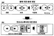
- FIG. 1 is a conceptual diagram showing a step-by-step mechanism for the method for producing nanoparticles using carbon nanotubes of the present invention.
- Figure 3 is a photograph before and after the production of aluminum nanoparticles using carbon nanotubes according to a preferred embodiment of the present invention.
- SEM electron micrograph
- FIG. 5 is an electron microscope (SEM) analysis photograph of aluminum nanoparticles prepared using carbon nanotubes according to a preferred embodiment of the present invention.
- FIG. 6 is an EDS component analysis data of aluminum nanoparticles prepared using carbon nanotubes according to a preferred embodiment of the present invention.
- TEM 7 is a transmission electron microscope (TEM) analysis data of aluminum nanoparticles prepared using carbon nanotubes according to a preferred embodiment of the present invention.
- DLS 8 is a particle size measurement (DLS) data of aluminum nanoparticles manufactured using carbon nanotubes according to a preferred embodiment of the present invention.
- FIG. 9 is a measurement data of mechanical properties of a specimen prepared using aluminum nanoparticles prepared using carbon nanotubes according to a preferred embodiment of the present invention.
- FIG. 10 is a measurement data of electrical conductivity of aluminum for casting using aluminum nanoparticles manufactured using carbon nanotubes according to a preferred embodiment of the present invention.
- FIG. 11 is a photograph of oxidative properties of aluminum nanoparticles prepared using carbon nanotubes according to a preferred embodiment of the present invention.
- FIG. 13 is a photograph before and after the preparation of the polymer nanoparticles prepared using carbon nanotubes according to a preferred embodiment of the present invention.
- 16 is an electron micrograph (SEM) analysis photo before and after the manufacture of the ceramic nanoparticles prepared using carbon nanotubes according to a preferred embodiment of the present invention.
- 17 is a conceptual diagram of the applicability of nanoparticles prepared using carbon nanotubes according to a preferred embodiment of the present invention.
- SEM electron microscopy
- the present invention provides a method for producing nanoparticles using carbon nanotubes.
- Carbon nanotubes consist of carbons with sp 2 hybrid bonds and are structurally stable. As a result, it has more than 100 times stronger mechanical properties than steel.
- the present invention provides a method of pulverizing a material after the physical force is applied to the carbon nanotubes to collide with the material.
- the manufacturing method of the present invention is largely composed of a grinding process by balls and a grinding process by carbon nanotubes.
- 1 is a conceptual diagram for illustrating the mechanism of the present invention.
- the ball milling process shown in FIG. When the micronization process of the powder particles by the ball proceeds, in general, the particles do not become smaller any longer, and welding of the particles occurs. Therefore, there is a limit to reducing the size of the particles due to the grinding method by the ball mill.
- the use of carbon nanotubes not only suppresses the welding process between the particles, but also carbon nanotubes crush the particles.
- carbon nanotubes show a mechanism for pulverizing micro-sized fine particles to nano-sized. Through such a mechanism that the carbon nanotubes pulverize the microparticles, particles of various kinds of materials such as metals, polymers and ceramics can be pulverized.
- the carbon nanotubes multilayer carbon nanotubes (Hanhan Nanotech, CM95) having a thickness of 10 to 20 nm and a length of 10 to 20 ⁇ m were used.
- Aluminum powder was used as a product purchased from Samjeon Chemical with a size of 70 ⁇ m.
- Aluminum particles and carbon nanotubes were placed in a steel ball mill (Pyung Tae Science) made of SKD 11 material and purged with argon (Ar), an inert gas, to prevent oxidation of aluminum.
- Carbon nanotubes were used at 50 wt%.
- the ball mill was milled at 400 rpm for 1 hour, 3 hours, 6 hours, and 12 hours, respectively. At this time, the ball used was 5 mm zirconia ball (for DH.ML 1032).
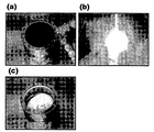
- Figure 3 is a photograph of the sample observed with a digital camera (Nikon, koolpix-3700) after the production of aluminum nanoparticles using carbon nanotubes.
- Figure 3 (a) is a photograph of 50 wt% carbon nanotubes and aluminum particles before the grinding process.
- 3B is a photograph of aluminum nanoparticles after pulverization. Aluminum nanoparticles were observed to increase beyond the initial volume after grinding. From this, it can be observed that the aluminum particles are micronized.
- 4 is a raw sample before the nanoparticle manufacturing process.
- 4 (a) is an electron microscope (SEM) (JEOL, JSM700F) photograph of carbon nanotubes observed at 30,000 ⁇ . Carbon nanotubes have a diameter of 10 ⁇ 20 nm and a length of 10 ⁇ 20 ⁇ m.
- 4B is a photograph of observing raw aluminum at 2,000 ⁇ . The size of the observed aluminum particles is not uniform and most are 10 ⁇ m or more.
- FIG. 5 is an electron micrograph of aluminum nanoparticles prepared using carbon nanotubes.
- Figure 5 (a) is an electron microscope photograph observed at 10,000x after one hour ball mill. After 1 hour of crushing, the aluminum particles form a lump, but the nanoparticles are observed on the surface.
- (B)-(d) are electron microscope photographs after 3 to 12 hours of grinding
- Figure 6 is a data analysis of the components of aluminum nanoparticles prepared using carbon nanotubes using energy dispersive spectroscopy (EDS) (Oxford). Component analysis was determined after 1 hour grinding of the bulk aluminum particles.
- 6 (a) is data showing the component spectra of EDS.
- Figure 6 (b) is a quantitative component analysis table calculated based on the spectrum of (a). As a result of observing the analysis table, it can be predicted that carbon nanotubes are included in the aluminum nanoparticles from the fact that carbon components are included.
- FIG. 7 is a transmission electron microscope (TEM) (JEOL, JEM2100F) observation photograph of aluminum nanoparticles.
- the transmission electron microscope can penetrate the nanoparticles and thus can observe the carbon nanotubes in the particles.
- FIG. 7A illustrates data obtained by measuring clusters of aluminum nanoparticles.
- (B)-(d) of FIG. 7 are enlarged analysis data about the measurement data of (a).
- carbon nanotubes are included between the inside and the nanoparticles. Through this analysis, it can be seen that carbon nanotubes play a role in crushing aluminum particles.
- FIG. 8 is a data of measuring distribution according to size of aluminum through DLS (Photal otsuka electronics, ELS-8000).
- DLS dipal otsuka electronics, ELS-8000.
- the x axis of FIG. 8 is ball mill time and the y axis is percent.
- Ds is the data of the particle group smaller than 1 ⁇ m and Dl was measured the distribution of the particle group larger than 1 ⁇ m.
- the size distribution of the particles was about 50%, and the proportions of more than 1 ⁇ m and less than each other were similar.
- the particles occupy less than 1 ⁇ m, which is 80% of the time, and a large amount of nanoparticles are produced. Therefore, it can be seen that the aluminum particles are changed to nano size according to the ball mill time.
- the mechanical properties of the sample using the aluminum nanoparticles prepared in the present invention were measured.
- Aluminum nanoparticles prepared by using carbon nanotubes for this embodiment were sintered by the spark plasma sintering method.
- the sintering method makes the powder bulk, and it is known that the smaller the particles of the powder, the better the mechanical properties.
- 9A is a value obtained by measuring the hardness of a sample sintered by the spark plasma sintering method. Hardness was measured according to the concentration of carbon nanotubes. The hardness of 50 Hv was observed in the sample without using carbon nanotubes, while the hardness of 500 Hv was observed in the sample prepared using 30 wt% of carbon nanotubes.
- the specimen prepared in the same manner was processed to the tensile specimen shape to measure the properties of the tension.
- Raw aluminum has a tensile strength of 93 MPa.
- Samples prepared using carbon nanotubes showed 134 MPa at 1 wt% of carbon nanotubes and 167 MPa at 5 wt%. That is, about 80% of tensile strength rose.
- Young's modulus was 372 MPa of raw aluminum, 650 MPa at 1 wt% of carbon nanotubes, and 839 MPa at 5 wt%. That is, the Young's modulus more than 2 times improved. Therefore, it can be observed that the improved mechanical properties appeared in the nanoparticles prepared using carbon nanotubes.
- FIG. 10 is a data of measuring electrical conductivity of an alloy in which a sample prepared by using carbon nanotubes is dissolved.
- the raw sample had a resistance of 84 ohm / sq, while the sample prepared with 0.5 wt% of carbon nanotubes showed 52 ohm / sq and 50 ohm / sq for 1 wt%.
- FIG. 11 is a data measuring the oxidative property of aluminum nanoparticles prepared using carbon nanotubes.
- FIG. 11A is a photograph of aluminum nanoparticles before ignition.
- Figure 12 (a) is a measurement of commercially available 3 ⁇ m size aluminum particles (trielectric chemistry). The ignition of aluminum proceeds above 650 °C and the heat of ignition is -82.3 kJ / mg.
- Figure 12 (b) is the data measured the aluminum nanoparticles prepared in the present invention. The heat of ignition measured on aluminum nanoparticles is -111.6 kJ / mg, which is higher than conventionally manufactured aluminum particles. Therefore, as a result of the present embodiment, when the aluminum nanoparticles are manufactured using carbon nanotubes, they exhibit high oxidative properties, so that they can be applied as explosives, spacecraft fuels, solid fuels, and the like that can ignite.
- Iron nanoparticles were prepared by the same method as the preparation method of Example 1-1. However, carbon nanotubes were used at 10 wt%, and the ball mill was milled for 6 hours.
- FIG. 18 Before and after the preparation of the iron nanoparticles prepared using carbon nanotubes were analyzed by an electron microscope (SEM) (Fig. 18).
- A) of FIG. 18 is a photograph of observing raw iron (Fe) particles at 100x.
- Figure 18 (b) is a photograph observing the iron nanoparticles after grinding using carbon nanotubes.
- SEM electron microscope
- Titanium nanoparticles were prepared by the same method as the preparation method of Example 1-1. However, carbon nanotubes were used at 16 wt%, and the ball mill was milled for 6 hours.
- FIG. 19 Before and after the production of titanium nanoparticles prepared using carbon nanotubes were analyzed by an electron microscope (SEM) (Fig. 19).
- 19A is a photograph of observing raw titanium (Ti) particles at 100x.
- 19 (b) is a photograph of observing titanium nanoparticles after grinding using carbon nanotubes.
- the present invention enables the production of titanium nanoparticles using carbon nanotubes.
- polymer nanoparticles were prepared using carbon nanotubes.
- Carbon nanotubes used in this example used C-150 P manufactured by Bayer.
- Polycarbonate (Samsung CHEIL INDUSTRIES, ISO-14000) was used as the polymer.
- This Example used a method similar to Example 1-1, the grinding time was 6 hours.
- 13 is a photograph before and after grinding.
- Figure 13 (a) is a photograph before the grinding and carbon nanotubes were added 20 wt%.
- Figure 13 (b) is a photograph pulverized for 6 hours using carbon nanotubes. The apparent volume was observed after grinding. As a result, it can be predicted that polycarbonate nanoparticles were formed.
- Example 2-2 Analysis of electron microscope (SEM) of the prepared polymer nanoparticles
- FIG. 14 is an electron microscope analysis of polycarbonate nanoparticles prepared using carbon nanotubes.
- Figure 14 (a) is an electron micrograph of the raw carbon nanotubes observed at 10,000x, the diameter is 5 ⁇ 20nm, the length is about 10 ⁇ m.
- 14B is an electron micrograph of the polycarbonate observed at 100 ⁇ . The diameter of the polycarbonate particles was about 100um.
- 14C is an electron microscope data (10,000 ⁇ ) of polycarbonate ground for 6 hours.
- D) of FIG. 14 shows the data of (c) expanded to 1000x. As a result, it can be confirmed that the polycarbonate is pulverized into nanoparticles by carbon nanotubes. Therefore, the present invention enables the production of polymer nanoparticles using carbon nanotubes.
- ceramic nanoparticles were prepared using carbon nanotubes.
- silicon carbide Aldrich, 357391, 400 mesh
- carbon nanotubes C 150-P manufactured by bayer was used as in Example 2-1.
- the concentration of carbon nanotubes was carried out at 50 wt%.
- This Example used a method similar to Example 1-1, the grinding time was 6 hours.
- 15 is a photograph before and after grinding the ceramic into nanoparticles.
- (A) is a photograph before grinding into nanoparticles
- (b) is a photograph after grinding into nanoparticles. The apparent volume was observed after grinding. As a result, it can be predicted that silicon carbide nanoparticles were formed.
- the silicon carbide nanoparticles prepared using carbon nanotubes were analyzed by electron microscopy.
- 16 is an electron microscope photograph of before and after preparing silicon carbide nanoparticles.
- FIG. 16A illustrates a photograph of raw silicon carbide at 100 ⁇ . The particle size is 10-30 ⁇ m.
- FIG. 16B is an electron micrograph after pulverization using carbon nanotubes. As a result, it can be seen that the size of the silicon carbide particles is reduced to a nano size of less than 1 ⁇ m. Therefore, the present invention enables the production of ceramic nanoparticles using carbon nanotubes.
- nanoparticles When aluminum is well oxidized, nanoparticles have a large specific surface area, and carbon nanotubes have high thermal conductivity, they can be used as ignition agents such as space aircraft propulsion fuels and gunpowder because they cause oxidation reactions in a short time. In addition, it can be used as a solid fuel by controlling the reaction time and can be used as a heating agent because it emits a high temperature of 1200 ° C. or more. In addition, by using the light properties of aluminum and mechanical properties of carbon nanotubes, it can be used as a light and strong high strength composite new material. 17 is a conceptual diagram showing an application to the characteristics of the nanoparticles produced by the present invention.
Landscapes
- Chemical & Material Sciences (AREA)
- Engineering & Computer Science (AREA)
- Materials Engineering (AREA)
- Organic Chemistry (AREA)
- Nanotechnology (AREA)
- Ceramic Engineering (AREA)
- Manufacturing & Machinery (AREA)
- Inorganic Chemistry (AREA)
- Structural Engineering (AREA)
- Metallurgy (AREA)
- Mechanical Engineering (AREA)
- General Physics & Mathematics (AREA)
- Crystallography & Structural Chemistry (AREA)
- Condensed Matter Physics & Semiconductors (AREA)
- Chemical Kinetics & Catalysis (AREA)
- Physics & Mathematics (AREA)
- Composite Materials (AREA)
- Carbon And Carbon Compounds (AREA)
- Manufacture Of Metal Powder And Suspensions Thereof (AREA)
- Powder Metallurgy (AREA)
Abstract
Description
Claims (18)
- (i) 분말 입자와 탄소나노튜브의 혼합물을 준비하는 단계; 및(ii) 상기 혼합물을 볼밀(ball mill)하여 분쇄하는 단계를 포함하는 나노입자를 제조하는 방법.
- 제1항에 있어서,탄소나노튜브는 단일벽 탄소나노튜브, 이중벽 탄소나노튜브, 얇은 다중벽 탄소나노튜브 및 다중벽 탄소나노튜브로 구성된 군으로부터 선택된 1종 또는 2종 이상의 혼합물임을 특징으로 하는 나노입자 제조방법.
- 제1항에 있어서,분말 입자는 금속임을 특징으로 하는 나노입자 제조방법.
- 제3항에 있어서,금속은 금, 은, 구리, 알루미늄, 망간, 철, 주석, 아연 및 티타늄으로 구성된 군으로부터 선택되는 어느 하나임을 특징으로 하는 나노입자 제조방법.
- 제3항에 있어서,금속은 알루미늄임을 특징으로 하는 나노입자 제조방법.
- 제1항 내지 제5항 중 어느 한 항에 있어서,단계 (i)에서 아르곤(Ar)으로 퍼징(purging)하는 단계를 추가로 포함함을 특징으로 하는 나노입자 제조방법.
- 제1항 내지 제5항 중 어느 한 항에 있어서,볼밀(ball mill)로 0.5 시간 내지 12시간 동안 100 rpm 내지 5000 rpm으로 분쇄함을 특징으로 하는 나노입자 제조방법.
- 제6항에 있어서,볼밀(ball mill)로 0.5 시간 내지 12시간 동안 100 rpm 내지 5000 rpm으로 분쇄함을 특징으로 하는 나노입자 제조방법.
- 볼밀(ball mill)에 의해 탄소나노튜브로 분쇄된 분말 입자 및 탄소나노튜브를 포함하는 나노입자 복합체.
- 제9항에 있어서,탄소나노튜브는 단일벽 탄소나노튜브, 이중벽 탄소나노튜브, 얇은 다중벽 탄소나노튜브 및 다중벽 탄소나노튜브로 구성된 군으로부터 선택된 1종 또는 2종 이상의 혼합물임을 특징으로 하는 나노입자 복합체.
- 제9항 또는 제10항에 있어서,분말 입자는 금속임을 특징으로 하는 나노입자 복합체.
- 제11항에 있어서,금속은 금, 은, 구리, 알루미늄, 망간, 철, 주석, 아연 및 티타늄으로 구성된 군으로부터 선택되는 어느 하나임을 특징으로 하는 나노입자 복합체.
- 제11항에 있어서,금속은 알루미늄임을 특징으로 하는 나노입자 복합체.
- 제9항에 있어서,분말 입자는 1 ㎛ 이상 1 cm 이하임을 특징으로 하는 나노입자 복합체.
- (i) 고분자 분말 입자와 탄소나노튜브의 혼합물을 준비하는 단계; 및(ii) 상기 혼합물을 볼밀(ball mill)하여 분쇄하는 단계를 포함하는 나노입자를 제조하는 방법.
- 볼밀(ball mill)에 의해 탄소나노튜브로 분쇄된 고분자 분말 입자 및 탄소나노튜브를 포함하는 나노입자 복합체.
- (i) 세라믹 분말 입자와 탄소나노튜브의 혼합물을 준비하는 단계; 및(ii) 상기 혼합물을 볼밀(ball mill)하여 분쇄하는 단계를 포함하는 나노입자를 제조하는 방법.
- 볼밀(ball mill)에 의해 탄소나노튜브로 분쇄된 세라믹 분말 입자 및 탄소나노튜브를 포함하는 나노입자 복합체.
Priority Applications (4)
| Application Number | Priority Date | Filing Date | Title |
|---|---|---|---|
| JP2011549068A JP2012516784A (ja) | 2009-02-05 | 2010-02-05 | カーボンナノチューブを使用して調製されたナノ粒子およびその調製方法 |
| US13/147,890 US20110309311A1 (en) | 2009-02-05 | 2010-02-05 | Nanoparticles prepared using carbon nanotube and preparation method therefor |
| EP10738763.1A EP2394952A4 (en) | 2009-02-05 | 2010-02-05 | USING NANOPARTICLES MANUFACTURED BY CARBON NANOTONES AND METHOD OF MANUFACTURING THEM |
| CN2010800067321A CN102395522A (zh) | 2009-02-05 | 2010-02-05 | 利用碳纳米管制备的纳米粒子及其制备方法 |
Applications Claiming Priority (4)
| Application Number | Priority Date | Filing Date | Title |
|---|---|---|---|
| KR20090009366 | 2009-02-05 | ||
| KR10-2009-0009366 | 2009-02-05 | ||
| KR10-2010-0010573 | 2010-02-04 | ||
| KR1020100010573A KR101173847B1 (ko) | 2009-02-05 | 2010-02-04 | 탄소나노튜브를 이용하여 제조된 나노입자 및 그 제조방법 |
Publications (2)
| Publication Number | Publication Date |
|---|---|
| WO2010090479A2 true WO2010090479A2 (ko) | 2010-08-12 |
| WO2010090479A3 WO2010090479A3 (ko) | 2010-11-25 |
Family
ID=42755875
Family Applications (1)
| Application Number | Title | Priority Date | Filing Date |
|---|---|---|---|
| PCT/KR2010/000729 Ceased WO2010090479A2 (ko) | 2009-02-05 | 2010-02-05 | 탄소나노튜브를 이용하여 제조된 나노입자 및 그 제조 방법 |
Country Status (6)
| Country | Link |
|---|---|
| US (1) | US20110309311A1 (ko) |
| EP (1) | EP2394952A4 (ko) |
| JP (1) | JP2012516784A (ko) |
| KR (1) | KR101173847B1 (ko) |
| CN (1) | CN102395522A (ko) |
| WO (1) | WO2010090479A2 (ko) |
Cited By (2)
| Publication number | Priority date | Publication date | Assignee | Title |
|---|---|---|---|---|
| EP2492241A1 (en) * | 2011-02-22 | 2012-08-29 | Research & Business Foundation of Sungkyunkwan University | Method of hardening interface of carbon material using nano silicon carbide coating |
| WO2014049207A1 (en) | 2012-09-25 | 2014-04-03 | Greenbutton Oy | Robust material, method of producing the same as well as uses thereof |
Families Citing this family (11)
| Publication number | Priority date | Publication date | Assignee | Title |
|---|---|---|---|---|
| KR100907334B1 (ko) * | 2008-01-04 | 2009-07-13 | 성균관대학교산학협력단 | 알루미늄과 탄소재료 간의 공유결합을 형성하는 방법, 알루미늄과 탄소재료 복합체를 제조하는 방법 및 그 방법에 의하여 제조된 알루미늄과 탄소재료 복합체 |
| KR101710159B1 (ko) * | 2010-09-14 | 2017-03-08 | 삼성전자주식회사 | Ⅲ족 질화물 나노로드 발광소자 및 그 제조 방법 |
| WO2012057800A1 (en) | 2010-10-29 | 2012-05-03 | Hewlett-Packard Development Company, L.P. | Metallic lep inks and associated methods |
| JP5744540B2 (ja) * | 2011-01-26 | 2015-07-08 | 新光電気工業株式会社 | 金属複合材料、金属複合材料の製造方法、放熱部品、及び放熱部品の製造方法 |
| EP2916123A1 (en) | 2014-03-07 | 2015-09-09 | Reagecon Diagnostics Ltd | Use of nanoparticles in the preparation of calibration standards |
| KR101850934B1 (ko) | 2016-09-22 | 2018-04-20 | 부경대학교 산학협력단 | 방전 플라즈마 소결 공정을 이용한 단일벽 탄소나노튜브 강화 금속기지 복합재료의 제조방법 및 이에 의해 제조된 복합재료 |
| US11234298B2 (en) * | 2018-11-15 | 2022-01-25 | Whirlpool Corporation | Hybrid nanoreinforced liner for microwave oven |
| CN110387281A (zh) * | 2019-06-26 | 2019-10-29 | 包头协同纳米新材科技有限公司 | 碳纳米管/零维纳米材料复合材料及其制法和应用 |
| US20230021998A1 (en) * | 2021-07-10 | 2023-01-26 | The United States Of America, As Represented By The Secretary Of The Navy | 3-d printed carbon nanotube reinforced titanium composites and methods |
| CN113603204A (zh) * | 2021-08-26 | 2021-11-05 | 中国海洋大学 | 一种铝-碳纳米管复合材料的制备方法及其在去除水中难降解的污染物中的应用 |
| CN115301942B (zh) * | 2022-07-15 | 2023-10-10 | 武汉大学 | 碳纳米管强韧化钛基体的激光增材制造方法 |
Citations (1)
| Publication number | Priority date | Publication date | Assignee | Title |
|---|---|---|---|---|
| KR20060101844A (ko) | 2005-03-21 | 2006-09-26 | 주식회사 안심푸드 | 위생 고추분말의 제조방법 및 그 장치 |
Family Cites Families (6)
| Publication number | Priority date | Publication date | Assignee | Title |
|---|---|---|---|---|
| US20040029706A1 (en) * | 2002-02-14 | 2004-02-12 | Barrera Enrique V. | Fabrication of reinforced composite material comprising carbon nanotubes, fullerenes, and vapor-grown carbon fibers for thermal barrier materials, structural ceramics, and multifunctional nanocomposite ceramics |
| KR100841754B1 (ko) * | 2005-05-17 | 2008-06-27 | 연세대학교 산학협력단 | 나노파이버를 금속 또는 폴리머 기지에 균일 분산시키는 방법 및 이를 이용하여 제조한 금속 또는 폴리머 복합재 |
| DE502006003829D1 (de) * | 2006-10-31 | 2009-07-09 | Alcan Tech & Man Ltd | Werkstoffe enthaltend Kohlenstoffnanoröhrchen, Verfahren zu deren Herstellung und Verwendung der Werkstoffe |
| KR100907334B1 (ko) * | 2008-01-04 | 2009-07-13 | 성균관대학교산학협력단 | 알루미늄과 탄소재료 간의 공유결합을 형성하는 방법, 알루미늄과 탄소재료 복합체를 제조하는 방법 및 그 방법에 의하여 제조된 알루미늄과 탄소재료 복합체 |
| EP2127784A1 (de) * | 2008-05-23 | 2009-12-02 | Alcan Technology & Management Ltd. | Verfahren zur Herstellung eines Bauteils aus einem Kompositwerkstoff |
| KR20100073506A (ko) * | 2008-12-23 | 2010-07-01 | 삼성전자주식회사 | 음극 활물질, 이를 포함하는 음극, 음극의 제조 방법 및 리튬 전지 |
-
2010
- 2010-02-04 KR KR1020100010573A patent/KR101173847B1/ko not_active Expired - Fee Related
- 2010-02-05 EP EP10738763.1A patent/EP2394952A4/en not_active Withdrawn
- 2010-02-05 JP JP2011549068A patent/JP2012516784A/ja active Pending
- 2010-02-05 US US13/147,890 patent/US20110309311A1/en not_active Abandoned
- 2010-02-05 CN CN2010800067321A patent/CN102395522A/zh active Pending
- 2010-02-05 WO PCT/KR2010/000729 patent/WO2010090479A2/ko not_active Ceased
Patent Citations (1)
| Publication number | Priority date | Publication date | Assignee | Title |
|---|---|---|---|---|
| KR20060101844A (ko) | 2005-03-21 | 2006-09-26 | 주식회사 안심푸드 | 위생 고추분말의 제조방법 및 그 장치 |
Non-Patent Citations (1)
| Title |
|---|
| See also references of EP2394952A4 |
Cited By (3)
| Publication number | Priority date | Publication date | Assignee | Title |
|---|---|---|---|---|
| EP2492241A1 (en) * | 2011-02-22 | 2012-08-29 | Research & Business Foundation of Sungkyunkwan University | Method of hardening interface of carbon material using nano silicon carbide coating |
| US8673053B2 (en) | 2011-02-22 | 2014-03-18 | Research & Business Foundation Of Sungkyunkwan University | Method of hardening an interface of carbon material using nano silicon carbide coating |
| WO2014049207A1 (en) | 2012-09-25 | 2014-04-03 | Greenbutton Oy | Robust material, method of producing the same as well as uses thereof |
Also Published As
| Publication number | Publication date |
|---|---|
| JP2012516784A (ja) | 2012-07-26 |
| WO2010090479A3 (ko) | 2010-11-25 |
| EP2394952A4 (en) | 2014-05-07 |
| EP2394952A2 (en) | 2011-12-14 |
| KR20100090216A (ko) | 2010-08-13 |
| KR101173847B1 (ko) | 2012-08-14 |
| CN102395522A (zh) | 2012-03-28 |
| US20110309311A1 (en) | 2011-12-22 |
Similar Documents
| Publication | Publication Date | Title |
|---|---|---|
| WO2010090479A2 (ko) | 탄소나노튜브를 이용하여 제조된 나노입자 및 그 제조 방법 | |
| So et al. | SiC formation on carbon nanotube surface for improving wettability with aluminum | |
| Steurer et al. | Functionalized graphenes and thermoplastic nanocomposites based upon expanded graphite oxide | |
| Inam et al. | Dimethylformamide: an effective dispersant for making ceramic–carbon nanotube composites | |
| EP2986557B1 (en) | Process for the production of boron nitride nanotubes | |
| Zeng et al. | A new technique for dispersion of carbon nanotube in a metal melt | |
| Li et al. | Synthesis of boron nitride nanotubes by boron ink annealing | |
| Dong et al. | Microstructural evaluation and mechanical properties of in-situ WC/W-Cu composites fabricated by rGO/W-Cu spark plasma sintering reaction | |
| CN108778994A (zh) | 石墨烯增强的无机基质复合材料的无化学品式生产 | |
| US20180073110A1 (en) | Method for making metal-carbon composites and compositions | |
| Zhang et al. | Designable interfacial structure and its influence on interface reaction and performance of MWCNTs reinforced aluminum matrix composites | |
| WO2013133467A1 (ko) | 판형 탄소 나노입자 제조방법 및 이를 이용한 알루미늄-탄소 복합재료의 제조방법 | |
| Yan et al. | Fabrication of carbon nanotube reinforced A356 nanocomposites | |
| Uriza-Vega et al. | Mechanical behavior of multiwalled carbon nanotube reinforced 7075 aluminum alloy composites prepared by mechanical milling and hot extrusion | |
| Kwon et al. | Extrusion of spark plasma sintered aluminum-carbon nanotube composites at various sintering temperatures | |
| JP2007254886A (ja) | 複合材料 | |
| KR101096059B1 (ko) | 구리 나노분말의 제조방법 | |
| Lee et al. | Fabrication of Tantalum and Hafnium Carbide Fibers via ForcespinningTM for Ultrahigh‐Temperature Applications | |
| Nabiyev | Influence of nanoparticle weight fraction on morphology and thermal properties of HDPE/SiO2 composite films | |
| Hirano et al. | Formation of gold and iron oxide nanoparticles encapsulated in boron nitride sheets | |
| Zhou et al. | The effect of surface coating treatment on the properties of carbon nanotube reinforced copper matrix composites | |
| KR101488619B1 (ko) | 기계 화학적 방법에 의한 그래핀 크기 조절 및 유기 용매에서의 분산성 향상 방법 | |
| CN108349820A (zh) | 硼化锆及其制备方法 | |
| WO2018062872A1 (ko) | 은-다이아몬드 복합 재료의 제조를 위한 방전플라즈마소결 방법 및 이에 의해 제조된 은-다이아몬드 복합 재료 | |
| Zhang et al. | Large-scale synthesis of AlN nanofibers by direct nitridation of aluminum |
Legal Events
| Date | Code | Title | Description |
|---|---|---|---|
| WWE | Wipo information: entry into national phase |
Ref document number: 201080006732.1 Country of ref document: CN |
|
| 121 | Ep: the epo has been informed by wipo that ep was designated in this application |
Ref document number: 10738763 Country of ref document: EP Kind code of ref document: A2 |
|
| WWE | Wipo information: entry into national phase |
Ref document number: 2010738763 Country of ref document: EP |
|
| WWE | Wipo information: entry into national phase |
Ref document number: 2011549068 Country of ref document: JP |
|
| NENP | Non-entry into the national phase |
Ref country code: DE |
|
| WWE | Wipo information: entry into national phase |
Ref document number: 13147890 Country of ref document: US |