WO2010095363A1 - プリンタ装置およびそのメンテナンス方法 - Google Patents
プリンタ装置およびそのメンテナンス方法 Download PDFInfo
- Publication number
- WO2010095363A1 WO2010095363A1 PCT/JP2010/000413 JP2010000413W WO2010095363A1 WO 2010095363 A1 WO2010095363 A1 WO 2010095363A1 JP 2010000413 W JP2010000413 W JP 2010000413W WO 2010095363 A1 WO2010095363 A1 WO 2010095363A1
- Authority
- WO
- WIPO (PCT)
- Prior art keywords
- ink
- vibration
- printer
- printer head
- drive control
- Prior art date
- Legal status (The legal status is an assumption and is not a legal conclusion. Google has not performed a legal analysis and makes no representation as to the accuracy of the status listed.)
- Ceased
Links
Images


Classifications
-
- B—PERFORMING OPERATIONS; TRANSPORTING
- B41—PRINTING; LINING MACHINES; TYPEWRITERS; STAMPS
- B41J—TYPEWRITERS; SELECTIVE PRINTING MECHANISMS, i.e. MECHANISMS PRINTING OTHERWISE THAN FROM A FORME; CORRECTION OF TYPOGRAPHICAL ERRORS
- B41J19/00—Character- or line-spacing mechanisms
- B41J19/18—Character-spacing or back-spacing mechanisms; Carriage return or release devices therefor
- B41J19/20—Positive-feed character-spacing mechanisms
- B41J19/202—Drive control means for carriage movement
-
- B—PERFORMING OPERATIONS; TRANSPORTING
- B41—PRINTING; LINING MACHINES; TYPEWRITERS; STAMPS
- B41J—TYPEWRITERS; SELECTIVE PRINTING MECHANISMS, i.e. MECHANISMS PRINTING OTHERWISE THAN FROM A FORME; CORRECTION OF TYPOGRAPHICAL ERRORS
- B41J29/00—Details of, or accessories for, typewriters or selective printing mechanisms not otherwise provided for
- B41J29/38—Drives, motors, controls or automatic cut-off devices for the entire printing mechanism
-
- B—PERFORMING OPERATIONS; TRANSPORTING
- B41—PRINTING; LINING MACHINES; TYPEWRITERS; STAMPS
- B41J—TYPEWRITERS; SELECTIVE PRINTING MECHANISMS, i.e. MECHANISMS PRINTING OTHERWISE THAN FROM A FORME; CORRECTION OF TYPOGRAPHICAL ERRORS
- B41J2/00—Typewriters or selective printing mechanisms characterised by the printing or marking process for which they are designed
- B41J2/005—Typewriters or selective printing mechanisms characterised by the printing or marking process for which they are designed characterised by bringing liquid or particles selectively into contact with a printing material
- B41J2/01—Ink jet
- B41J2/135—Nozzles
- B41J2/165—Prevention or detection of nozzle clogging, e.g. cleaning, capping or moistening for nozzles
- B41J2/16505—Caps, spittoons or covers for cleaning or preventing drying out
- B41J2/16508—Caps, spittoons or covers for cleaning or preventing drying out connected with the printer frame
-
- B—PERFORMING OPERATIONS; TRANSPORTING
- B41—PRINTING; LINING MACHINES; TYPEWRITERS; STAMPS
- B41J—TYPEWRITERS; SELECTIVE PRINTING MECHANISMS, i.e. MECHANISMS PRINTING OTHERWISE THAN FROM A FORME; CORRECTION OF TYPOGRAPHICAL ERRORS
- B41J2/00—Typewriters or selective printing mechanisms characterised by the printing or marking process for which they are designed
- B41J2/005—Typewriters or selective printing mechanisms characterised by the printing or marking process for which they are designed characterised by bringing liquid or particles selectively into contact with a printing material
- B41J2/01—Ink jet
- B41J2/135—Nozzles
- B41J2/165—Prevention or detection of nozzle clogging, e.g. cleaning, capping or moistening for nozzles
- B41J2/16517—Cleaning of print head nozzles
- B41J2/1652—Cleaning of print head nozzles by driving a fluid through the nozzles to the outside thereof, e.g. by applying pressure to the inside or vacuum at the outside of the print head
-
- B—PERFORMING OPERATIONS; TRANSPORTING
- B41—PRINTING; LINING MACHINES; TYPEWRITERS; STAMPS
- B41J—TYPEWRITERS; SELECTIVE PRINTING MECHANISMS, i.e. MECHANISMS PRINTING OTHERWISE THAN FROM A FORME; CORRECTION OF TYPOGRAPHICAL ERRORS
- B41J2/00—Typewriters or selective printing mechanisms characterised by the printing or marking process for which they are designed
- B41J2/005—Typewriters or selective printing mechanisms characterised by the printing or marking process for which they are designed characterised by bringing liquid or particles selectively into contact with a printing material
- B41J2/01—Ink jet
- B41J2/135—Nozzles
- B41J2/165—Prevention or detection of nozzle clogging, e.g. cleaning, capping or moistening for nozzles
- B41J2/16517—Cleaning of print head nozzles
- B41J2/1652—Cleaning of print head nozzles by driving a fluid through the nozzles to the outside thereof, e.g. by applying pressure to the inside or vacuum at the outside of the print head
- B41J2/16526—Cleaning of print head nozzles by driving a fluid through the nozzles to the outside thereof, e.g. by applying pressure to the inside or vacuum at the outside of the print head by applying pressure only
-
- B—PERFORMING OPERATIONS; TRANSPORTING
- B41—PRINTING; LINING MACHINES; TYPEWRITERS; STAMPS
- B41J—TYPEWRITERS; SELECTIVE PRINTING MECHANISMS, i.e. MECHANISMS PRINTING OTHERWISE THAN FROM A FORME; CORRECTION OF TYPOGRAPHICAL ERRORS
- B41J2/00—Typewriters or selective printing mechanisms characterised by the printing or marking process for which they are designed
- B41J2/005—Typewriters or selective printing mechanisms characterised by the printing or marking process for which they are designed characterised by bringing liquid or particles selectively into contact with a printing material
- B41J2/01—Ink jet
- B41J2/17—Ink jet characterised by ink handling
- B41J2/175—Ink supply systems ; Circuit parts therefor
-
- B—PERFORMING OPERATIONS; TRANSPORTING
- B41—PRINTING; LINING MACHINES; TYPEWRITERS; STAMPS
- B41J—TYPEWRITERS; SELECTIVE PRINTING MECHANISMS, i.e. MECHANISMS PRINTING OTHERWISE THAN FROM A FORME; CORRECTION OF TYPOGRAPHICAL ERRORS
- B41J2/00—Typewriters or selective printing mechanisms characterised by the printing or marking process for which they are designed
- B41J2/005—Typewriters or selective printing mechanisms characterised by the printing or marking process for which they are designed characterised by bringing liquid or particles selectively into contact with a printing material
- B41J2/01—Ink jet
- B41J2/17—Ink jet characterised by ink handling
- B41J2/175—Ink supply systems ; Circuit parts therefor
- B41J2/17503—Ink cartridges
- B41J2/17506—Refilling of the cartridge
- B41J2/17509—Whilst mounted in the printer
-
- B—PERFORMING OPERATIONS; TRANSPORTING
- B41—PRINTING; LINING MACHINES; TYPEWRITERS; STAMPS
- B41J—TYPEWRITERS; SELECTIVE PRINTING MECHANISMS, i.e. MECHANISMS PRINTING OTHERWISE THAN FROM A FORME; CORRECTION OF TYPOGRAPHICAL ERRORS
- B41J2/00—Typewriters or selective printing mechanisms characterised by the printing or marking process for which they are designed
- B41J2/005—Typewriters or selective printing mechanisms characterised by the printing or marking process for which they are designed characterised by bringing liquid or particles selectively into contact with a printing material
- B41J2/01—Ink jet
- B41J2/17—Ink jet characterised by ink handling
- B41J2/175—Ink supply systems ; Circuit parts therefor
- B41J2/17596—Ink pumps, ink valves
-
- B—PERFORMING OPERATIONS; TRANSPORTING
- B41—PRINTING; LINING MACHINES; TYPEWRITERS; STAMPS
- B41J—TYPEWRITERS; SELECTIVE PRINTING MECHANISMS, i.e. MECHANISMS PRINTING OTHERWISE THAN FROM A FORME; CORRECTION OF TYPOGRAPHICAL ERRORS
- B41J2/00—Typewriters or selective printing mechanisms characterised by the printing or marking process for which they are designed
- B41J2/005—Typewriters or selective printing mechanisms characterised by the printing or marking process for which they are designed characterised by bringing liquid or particles selectively into contact with a printing material
- B41J2/01—Ink jet
- B41J2/17—Ink jet characterised by ink handling
- B41J2/18—Ink recirculation systems
- B41J2/185—Ink-collectors; Ink-catchers
-
- B—PERFORMING OPERATIONS; TRANSPORTING
- B41—PRINTING; LINING MACHINES; TYPEWRITERS; STAMPS
- B41J—TYPEWRITERS; SELECTIVE PRINTING MECHANISMS, i.e. MECHANISMS PRINTING OTHERWISE THAN FROM A FORME; CORRECTION OF TYPOGRAPHICAL ERRORS
- B41J2/00—Typewriters or selective printing mechanisms characterised by the printing or marking process for which they are designed
- B41J2/005—Typewriters or selective printing mechanisms characterised by the printing or marking process for which they are designed characterised by bringing liquid or particles selectively into contact with a printing material
- B41J2/01—Ink jet
- B41J2/135—Nozzles
- B41J2/165—Prevention or detection of nozzle clogging, e.g. cleaning, capping or moistening for nozzles
- B41J2/16517—Cleaning of print head nozzles
- B41J2002/16567—Cleaning of print head nozzles using ultrasonic or vibrating means
Definitions
- the present invention relates to a printer apparatus that performs printing by discharging ink from a printer head, and a maintenance method that is applied to the printer head.
- the printer device discharges ink from discharge nozzles formed on the lower surface of the printer head while moving the printer head relative to the print medium, thereby forming a predetermined pattern on the print medium. It is configured to print by adhering. At this time, the ink is ejected as fine droplets, and the ejected ink is deposited on the surface of the print medium so that desired printing is performed.
- printer heads have been developed that are configured to change the volume of an ink chamber by vibrating a vibration element such as a piezo element and to discharge ink from an ejection nozzle that communicates with the ink chamber.
- a vibration element such as a piezo element
- FIG. 2 of Patent Document 1 the piezoelectric vibrator 6 as a vibration element is expanded or contracted to cause pressure fluctuation in the ink filled in the ink chamber 71, and the ink is ejected from the nozzle opening 51.
- a configuration is disclosed.
- a conventional printer device is equipped with a maintenance unit for recovering ink so that ink can be normally discharged from the discharge nozzles.
- a maintenance unit for recovering ink so that ink can be normally discharged from the discharge nozzles.
- the inside of the cap is set to a negative pressure, and the ink in the printer head (ink chamber) is sucked toward the cap, and the sucked ink Along with it, foreign matter and bubbles are sucked and removed.
- the above-mentioned method for removing foreign matters and the like is to suck the ink in the printer head toward the cap without vibrating the vibrating element as in printing, and suck the foreign matters and the like together with the sucked ink. It was to be removed. For this reason, for example, foreign matters that adhere relatively firmly to the inside of the discharge nozzle or the inside of the vibration element may not be removed by the above-described method. In such a case, the ink may not be ejected from the ejection nozzle or may be ejected in a curved manner without being ejected straight toward the print medium, making it difficult to land the ink at a target position in a desired pattern. There was a problem of becoming.
- the present invention has been made in view of the above problems, and provides a printer device capable of removing foreign matter and the like in a printer head while having a relatively simple configuration, and a maintenance method using the printer device. Objective.
- a printer apparatus is opposed to a medium support unit (for example, a platen 12a in the embodiment) that supports a print medium (for example, the print sheet M in the embodiment), and the medium support unit.
- a guide rail that is relatively moved in a predetermined transport direction with respect to the print medium supported by the print medium and extends in a scanning direction orthogonal to the predetermined transport direction, and reciprocates in the scanning direction with respect to the guide rail.
- the volume of the ink chamber that is movably provided and communicates with the nozzle opening that opens downward (for example, the ejection nozzle 25a in the embodiment) is used for the vibration of the vibration element (for example, the piezoelectric element 24 in the embodiment).
- a printer head that ejects ink from the nozzle openings by changing the drive, and a drive control unit that controls the vibration of the vibration element (example: For example, the controller 13b) in the embodiment performs the control to vibrate the vibration element and performs the maintenance of the printer head by discharging ink using the vibration of the vibration element. .
- a receiving member for example, the cap member 45 in the embodiment
- the maintenance of the printer head is performed by discharging ink using the vibration of the vibration element.
- the ink chamber is connected to an ink tank (for example, the ink cartridge 51 in the embodiment) in which ink is stored via an ink supply path (for example, the supply tube 52 in the embodiment).
- the ink stored in the ink tank is supplied to the ink chamber by a supply pump provided in the path, and the drive control unit is configured to perform drive control of the supply pump,
- the drive control unit When performing maintenance of the printer head, the drive control unit preferably performs control to continuously drive the supply pump.
- the ink chamber is connected to an ink tank in which ink is stored via an ink supply path, and ink stored in the ink tank is supplied by a supply pump provided in the ink supply path.
- the supply control unit is configured to supply the ink chamber, and the drive control unit is configured to perform drive control of the supply pump.
- the drive control unit is configured to supply the supply pump. It is also preferable to perform control to stop the driving of the motor.
- the volume of the ink chamber which is provided so as to be reciprocally movable along the guide rail and communicates with the nozzle opening that opens downward, is changed by utilizing the vibration of the vibration element.
- a maintenance method for a printer head that discharges ink from a nozzle opening wherein the printer head is moved to the vicinity of an end of the guide rail, and is provided near the end of the guide rail to discharge from the nozzle opening.
- the printer apparatus is configured to perform control for vibrating the vibration element by the drive control unit, and to perform maintenance of the printer head by discharging ink using the vibration of the vibration element.
- a flexible film member for example, a vibration element
- ink chamber can be easily peeled off using the vibration of the vibration element. Therefore, it is possible to reliably prevent foreign matter in the printer head while maintaining a relatively simple configuration in which a part of vibration control performed on the vibration element is changed without adding a new component compared to the conventional configuration. Can be removed.
- the printer head is maintained by ejecting ink using the vibration of the vibration element in a state where the nozzle opening is opposed to and spaced from the receiving member.
- the vibration of the vibration element When configured in this way, it is possible to efficiently receive and collect the ink, foreign matters, and the like discharged during the maintenance by the receiving member without being scattered around.
- the receiving member since the receiving member is separated from the nozzle opening, the ink discharged at the time of maintenance is discharged into the atmosphere. Therefore, for example, compared with a case where the nozzle opening is covered with the receiving member, a meniscus is easily formed in the nozzle opening.
- the drive control unit When performing maintenance of the printer head, the drive control unit preferably performs control to continuously drive the supply pump.
- the control is performed in this way, the foreign matter and the like separated using the vibration of the vibration element can be reliably removed by being ejected together with the ink.
- foreign matter or the like attached to the inside of the vibration element forming the ink chamber is peeled off using the vibration of the vibration element, and the ink discharged at this time and the peeled foreign matter or the like are scattered around. Without being received by the receiving member.
- FIG. 1 is a front view of a printer apparatus to which the present invention is applied. It is the perspective view which showed the head unit periphery of the said printer apparatus.
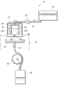
- FIG. 4 is a cross-sectional view illustrating a state where maintenance is performed on the printer head.
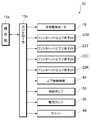
- FIG. 3 is a control system diagram of the printer apparatus. It is the table
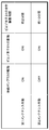
- movement. 6 is a table showing the number of printer heads that can be recovered in the conventional case and in the case where the present invention is applied.
- FIGS. 1 is a front view of the printer apparatus 10
- FIG. 2 is a perspective view of the vicinity of a head unit 20 to be described later
- FIG. 3 is a sectional view in a state where maintenance is performed on a printer head 22 to be described later
- FIG. A control system diagram of the printer apparatus 10 is shown.
- the printer device 10 is provided on a left side of the support body 11 having left and right support legs 11 a and 11 b, a center body part 12 supported by the support legs 11, and the center body part 12.
- the central body portion 12 is provided with a platen 12a that is exposed on the upper surface and extends to the left and right.
- an operation part 13a composed of operation switches and display devices is provided. Inside the left body portion 13, an operation signal is input from the operation portion 13 a, and a controller 13 b is provided that outputs an operation signal to each component of the printer device 10 and controls these operations. Yes.
- the controller 13b includes a left and right drive motor 19 described later, printer heads (piezo elements 24) 22M, 22Y, 22C, and 22K, a vertical movement mechanism 43, a supply pump 53, and a suction pump 55. And an operation signal is output to the wiper 48 and the like.
- a maintenance unit 40 is disposed inside the left body portion 13 on the left side of the platen 12a. The configuration of the maintenance unit 40 will be described later.
- a guide rail 15a extending left and right is provided inside the upper body portion 15, and a head unit 20 is attached to the left and right along the guide rail 15a. Further, a printing sheet M to be printed is sandwiched between a clamping device (not shown) disposed at the lower part of the upper body portion 15 and a feed roller (not shown) exposed to the platen 12a. By rotating the feed roller, the printing sheet M can be fed forward or backward by a predetermined distance.
- the head unit 20 is mainly composed of a carriage 21 and a printer head 22.
- the rear surface of the carriage 21 is fitted with the guide rail 15a, and can be reciprocated left and right along the guide rail 15a.
- the carriage 21 is reciprocated left and right by a left and right drive motor 19 (see FIG. 1) provided inside the right body portion 14.
- the printer head 22 includes magenta (M), yellow (Y), cyan (C), and black (K) printer heads 22M, 22Y, 22C, and 22K, and is mounted on the carriage 21.
- These printer heads 22M, 22Y, 22C, and 22K have substantially the same configuration, and the printer head 22 of FIG. 3 shows a cross-sectional view of any one of the above four. Note that the printer head 22 of FIG. 3 schematically shows only the main part.
- FIG. 3 shows a cross-sectional view of the printer head 22.
- the printer head 22 includes a case member 23 that covers the side and the upper side, piezoelectric elements 24 and 24 as vibration elements, and a printer head.
- the nozzle plate 25 which forms the lower surface of 22 is mainly configured.
- the nozzle plate 25 is configured by, for example, a plurality of discharge nozzles 25a penetrating vertically in a plate-like material.
- the piezo element 24 is a kind of piezoelectric element that vibrates by converting an applied voltage into force, and is applied with a voltage based on an operation signal from the controller 13b so as to vibrate left and right in the state shown in FIG. It has become.
- the printer head 22 is connected to an ink cartridge 51 detachably attached to the rear surface of the right body portion 14 via a supply tube 52 (see FIGS. 1 and 3). As shown in FIG. 3, by driving a supply pump 53 disposed in the supply tube 52, the ink stored in the ink cartridge 51 can be supplied to the ink chamber 24a.
- the supply pump 53 is driven and controlled based on an operation signal from the controller 13b.
- the maintenance unit 40 is mainly composed of a base plate 41 provided with a cap member 45 and a unit main body 42 provided therein with a vertical movement mechanism 43 capable of moving the base plate 41 up and down. .
- a vertical movement mechanism 43 capable of moving the base plate 41 up and down.
- cap members 45 corresponding to the number of the printer heads 22 and the shape of the nozzle plate 25 are attached side by side.
- the base plate 41 can be moved up and down with respect to the unit main body 42 by a vertical movement mechanism 43.
- one end of the discharge tube 54 is connected to the bottom of each cap member 45, and the other end is connected to the waste ink tank 56.
- a suction pump 55 made of, for example, a tube pump is disposed.
- the head unit 20 is positioned above the maintenance unit 40, and the cap member 45 is moved upward by the vertical movement mechanism 43 to cover the lower surface of the printer head 22. It has become. By doing so, it is possible to prevent thickening of the ink filled in the ink chamber 24a and the discharge nozzle 25a.
- FIG. 2 illustrates the wiper 48 in a state of moving rearward.
- the wiper 48 is always moved forward (not shown).
- the head unit 20 moves left and right while moving backward, the lower surface of the printer head 22 and the wiper 48 are moved. It is comprised so that the upper part of may contact
- abutting By abutting in this way, foreign matter or the like attached to the lower surface of the printer head 22 can be removed.
- a meniscus is easily formed on the discharge nozzle 25a.
- the configuration of the printer apparatus 10 has been described so far, but the operation when printing is performed on the print sheet M using the printer apparatus 10 will be described below.
- Printing is started by the operator operating the operation unit 13a, and the piezo element 24 is vibrated while the printer head 22 is reciprocated left and right along the guide rail 15a with respect to the print sheet M positioned on the platen 12a.
- ink is ejected downward from the ejection nozzle 25a.
- printing is performed by attaching ink in a desired pattern to the surface of the printing sheet M.
- the feed roller is rotated to feed the print sheet M forward by a predetermined distance, and then the ink is attached to the print sheet M while the carriage 21 is reciprocated back and forth again.
- the printed sheet M on which the printing has been performed is wound up in a roll shape on the front side of the printer device 10, for example.
- the head unit 20 is moved above the maintenance unit 40. Then, the nozzle plate 25 and the cap member 45 are vertically opposed to each other, and as shown in FIG. 3, the nozzle member 25 and the cap member 45 are separated from each other without covering the lower surface (nozzle plate 25) of the printer head 22.
- the piezo element 24 is vibrated at a time interval of, for example, about 80 ⁇ sec (80 ⁇ 10 ⁇ 6 seconds) (see the upper part of FIG. 5).
- the plurality of ink chambers 24a of the printer head 22 are divided into, for example, three groups, and the first maintenance operation is continuously performed, for example, for about 2 minutes while vibrating at a time interval of about 80 ⁇ sec for each group.
- the meniscus can be accurately formed in the discharge nozzle 25a. For this reason, for example, the frequency of cleaning the lower surface of the printer head 22 by the wiper 48 and performing the first maintenance operation can be reduced.
- the vibration width of the piezo element 24 at this time is set to be approximately the same as that when the smallest ink droplet is ejected from the printer head 22, for example.
- the smallest ink droplet will be described on the assumption that the printer device 10 is configured to be able to set three printing resolutions of, for example, 300 dpi, 600 dpi, and 1200 dpi.
- the print resolution is set to 1200 dpi, printing expressed in a delicate manner is performed by ejecting smaller ink droplets than in the case of setting to another print resolution.
- the piezoelectric element 24 is vibrated greatly so that, for example, in the case of 600 dpi, four times (four drops) of ink is ejected as one droplet.
- the piezo element 24 is further vibrated so that printing is performed by ejecting seven times (seven drops) of ink as one drop.
- the vibration width of the piezo element 24 is set to a vibration width that allows ink droplets for 1200 dpi to be ejected.
- the foreign matter 24b adhering to the inside of the piezo element 24 can be vibrated left and right, and can be separated from the piezo element 24 relatively easily.
- the separated foreign matter 24b is discharged together with the ink flowing toward the discharge nozzle 25a in the ink chamber 24a and is received by the cap member 45.
- the suction pump 55 By operating the suction pump 55 during the first maintenance operation, the discharged ink and the foreign matter 24b can be stored in the waste ink tank 56 via the discharge tube 54.
- the bubbles 25b in the vicinity of the discharge nozzle 25a can be discharged and removed together with the ink flowing from the ink chamber 24a toward the discharge nozzle 25a.
- the maintenance is performed by the second maintenance operation that vibrates the piezo element 24 in the same manner as described above with the drive of the supply pump 53 stopped. Is also possible.
- the second maintenance operation is performed in a state where the cap member 45 is separated without covering the lower surface (nozzle plate 25) of the printer head 22 (see FIG. 3).
- the foreign matter 24b attached to the inside of the piezo element 24 can be vibrated to the left and right to be separated from the piezo element 24.
- the peeled foreign matter 24 b is discharged from the discharge nozzle 25 a together with the ink and is received by the cap member 45.
- FIG. 6 a plurality of printer heads (for example, product model number CA4 manufactured by TOSHIBA TEC Co., Ltd.) in which ejection failure has occurred are collected, and various maintenance operations are performed on these to recover how much ejection failure is recovered.
- the experimental results are shown.
- FIG. 6 an experiment in the case where the conventional maintenance operation for driving the supply pump 53 and the suction pump 55 is performed with the cap member 45 covering the lower surface of the printer head 22 without vibrating the piezo 24. Results are shown. In this case, only 9 out of 27 (33%) could be recovered.
- FIG. 6 shows the experimental results when the first maintenance operation is first performed, and the second maintenance operation is performed for those in which the discharge failure does not recover. In this case, ejection failure of 4 out of 6 (67%) printer heads could be recovered.
- the discharge failure can be recovered with high probability by performing the first or second maintenance operation without replacing the new printer head 22. Therefore, for example, since the frequency of replacing the printer head 22 in which ejection failure has occurred is reduced, it is possible to save the labor of such replacement work and to improve the operating efficiency of the printer apparatus 10.
- the present invention is not limited to this configuration.
- the ink chamber 24a is filled with ink by replacing with a new printer head 22, by filling the ink while performing the first or second maintenance operation, the ink is not mixed with foreign matter or bubbles. It is possible to fill.
- the time interval (about 80 ⁇ sec) for vibrating the piezo element 24 described in the above embodiment and the time for performing the maintenance operation are merely examples, and are not limited to these.
- the time for performing the maintenance operation can be reliably removed by setting the maintenance operation time longer than the above.
- the printer head 22 having a configuration in which the piezo element 24 is disposed in contact with the ink stored in the ink chamber 24a (a configuration in which the ink chamber 24a is formed by the piezo element 24) is illustrated.
- the present invention is also applied to a printer head having a configuration in which the ink chamber 24a is formed using a flexible film member and the piezo element 24 is disposed in contact with the outside of the film member. Is possible.
- the film member is vibrated in accordance with the vibration of the piezo element 24 during maintenance operation, and foreign matter or the like adhering to the inside of the film member is peeled off together with the ink from the discharge nozzle 25a. It can be discharged (discharged).
- the configuration example applied to the printer device 10 of the uniaxial printing medium movement type and the uniaxial printer head movement type is described as an example of the printer device to which the present invention is applied.
- the present invention is limited to this configuration. Not applicable.
- it can be applied to a printer device of a biaxial printer head moving type and a printer device of a biaxial printing medium moving type, and the ink used is another type of ink such as an ultraviolet curable ink.
- the present invention can also be applied to a printer device.
- Print sheet (print medium) 10 Printer device 12a Platen (medium support means) 13b Controller (drive control unit) 15a guide rail 22 printer head 24 piezo element (vibration element) 24a Ink chamber 25a Discharge nozzle (nozzle opening) 45 Cap member (receiving member) 51 Ink cartridge (ink tank) 52 Supply tube (ink supply path) 53 Supply pump
Landscapes
- Ink Jet (AREA)
Abstract
Description
10 プリンタ装置
12a プラテン(媒体支持手段)
13b コントローラ(駆動制御部)
15a ガイドレール
22 プリンタヘッド
24 ピエゾ素子(振動素子)
24a インク室
25a 吐出ノズル(ノズル開口)
45 キャップ部材(受容部材)
51 インクカートリッジ(インクタンク)
52 供給チューブ(インク供給路)
53 供給ポンプ
Claims (5)
- 印刷媒体を支持する媒体支持手段と対向し、前記媒体支持手段に支持された印刷媒体に対して所定搬送方向に相対移動されるとともに前記所定搬送方向に対して直交する走査方向に延びて設けられたガイドレールと、
前記ガイドレールに対して前記走査方向に往復移動自在に設けられて、下方に向けて開口したノズル開口と連通したインク室の容積を、振動素子の振動を利用して変化させて前記ノズル開口からインクを吐出するプリンタヘッドと、
前記振動素子の振動を制御する駆動制御部とを有したプリンタ装置において、
前記駆動制御部は、前記振動素子を振動させる制御を行うとともに前記振動素子の振動を利用してインクを吐出させて前記プリンタヘッドのメンテナンスを行うことを特徴とするプリンタ装置。 - 前記ガイドレールにおける前記走査方向の端部近傍には、前記ノズル開口から吐出されるインクを受容する受容部材が設けられており、
前記プリンタヘッドを前記ガイドレールの前記走査方向における端部に移動させ、前記受容部材に対して前記ノズル開口を対向させるとともに離間させた状態で、前記駆動制御部により前記振動素子を振動させる制御を行うとともに前記振動素子の振動を利用してインクを吐出させて前記プリンタヘッドのメンテナンスを行うことを特徴とする請求項1に記載のプリンタ装置。 - 前記インク室は、インクが貯留されたインクタンクとインク供給路を介して接続され、
前記インク供給路に設けられた供給ポンプにより、前記インクタンクに貯留されたインクが前記インク室に供給されるように構成され、
前記駆動制御部は、前記供給ポンプの駆動制御を行うように構成され、
前記プリンタヘッドのメンテナンスを行うときに、
前記駆動制御部は、前記供給ポンプを連続して駆動させる制御を行うことを特徴とする請求項1または2に記載のプリンタ装置。 - 前記インク室は、インクが貯留されたインクタンクとインク供給路を介して接続され、
前記インク供給路に設けられた供給ポンプにより、前記インクタンクに貯留されたインクが前記インク室に供給されるように構成され、
前記駆動制御部は、前記供給ポンプの駆動制御を行うように構成され、
前記プリンタヘッドのメンテナンスを行うときに、
前記駆動制御部は、前記供給ポンプの駆動を停止させておく制御を行うことを特徴とする請求項1または2に記載のプリンタ装置。 - ガイドレールに沿って往復移動自在に設けられて、下方に向けて開口したノズル開口と連通したインク室の容積を、振動素子の振動を利用して変化させて前記ノズル開口からインクを吐出するプリンタヘッドに対して施すメンテナンス方法であって、
前記プリンタヘッドを前記ガイドレールの端部近傍に移動させ、前記ガイドレールの端部近傍に設けられて前記ノズル開口から吐出されるインクを受容可能な受容部材に対して、前記ノズル開口を対向させるとともに離間させるように位置させる第1のステップと、
前記振動素子の振動を利用してインクを吐出させて前記プリンタヘッドのメンテナンスを行う第2のステップとを有することを特徴とするメンテナンス方法。
Priority Applications (5)
| Application Number | Priority Date | Filing Date | Title |
|---|---|---|---|
| US13/147,803 US20110304670A1 (en) | 2009-02-19 | 2010-01-26 | Printer device and maintenance method thereof |
| EP10743495.3A EP2399749A4 (en) | 2009-02-19 | 2010-01-26 | PRINTER DEVICE AND MAINTENANCE METHOD THEREFOR |
| KR1020117017419A KR101344430B1 (ko) | 2009-02-19 | 2010-01-26 | 프린터 장치 및 그 유지보수 방법 |
| CN201080007805.9A CN102317080B (zh) | 2009-02-19 | 2010-01-26 | 打印装置及其维护方法 |
| US13/921,190 US20130278676A1 (en) | 2009-02-19 | 2013-06-18 | Printer device and maintenance method thereof |
Applications Claiming Priority (2)
| Application Number | Priority Date | Filing Date | Title |
|---|---|---|---|
| JP2009036557A JP5236523B2 (ja) | 2009-02-19 | 2009-02-19 | プリンタ装置およびそのメンテナンス方法 |
| JP2009-036557 | 2009-02-19 |
Related Child Applications (1)
| Application Number | Title | Priority Date | Filing Date |
|---|---|---|---|
| US13/921,190 Division US20130278676A1 (en) | 2009-02-19 | 2013-06-18 | Printer device and maintenance method thereof |
Publications (1)
| Publication Number | Publication Date |
|---|---|
| WO2010095363A1 true WO2010095363A1 (ja) | 2010-08-26 |
Family
ID=42633654
Family Applications (1)
| Application Number | Title | Priority Date | Filing Date |
|---|---|---|---|
| PCT/JP2010/000413 Ceased WO2010095363A1 (ja) | 2009-02-19 | 2010-01-26 | プリンタ装置およびそのメンテナンス方法 |
Country Status (6)
| Country | Link |
|---|---|
| US (2) | US20110304670A1 (ja) |
| EP (1) | EP2399749A4 (ja) |
| JP (1) | JP5236523B2 (ja) |
| KR (1) | KR101344430B1 (ja) |
| CN (1) | CN102317080B (ja) |
| WO (1) | WO2010095363A1 (ja) |
Families Citing this family (8)
| Publication number | Priority date | Publication date | Assignee | Title |
|---|---|---|---|---|
| JP2012151915A (ja) * | 2011-01-14 | 2012-08-09 | Toshiba Corp | 密閉型開閉装置 |
| JP2013001065A (ja) * | 2011-06-21 | 2013-01-07 | Ricoh Co Ltd | 画像形成装置、制御方法、及びプログラム |
| JP6368565B2 (ja) * | 2014-07-07 | 2018-08-01 | 株式会社ミマキエンジニアリング | インクジェット記録装置およびインクジェット記録方法 |
| CN104290456B (zh) * | 2014-09-24 | 2017-05-03 | 合肥海闻自动化设备有限公司 | 一种用于轮胎数字打印机的供墨系统 |
| JP2020516488A (ja) | 2017-04-12 | 2020-06-11 | ヒューレット−パッカード デベロップメント カンパニー エル.ピー.Hewlett‐Packard Development Company, L.P. | 印刷サブアセンブリ |
| EP4011630B1 (en) * | 2020-12-14 | 2025-02-12 | Canon Production Printing Holding B.V. | Cleaning method for ink jet imaging device |
| JP7621172B2 (ja) | 2021-04-23 | 2025-01-24 | 理想科学工業株式会社 | キャッピング装置 |
| CN116001464B (zh) * | 2021-10-23 | 2025-08-19 | 深圳市汉森软件股份有限公司 | 喷头振动打印方法、装置、设备及存储介质 |
Citations (6)
| Publication number | Priority date | Publication date | Assignee | Title |
|---|---|---|---|---|
| JPH10278302A (ja) * | 1997-04-10 | 1998-10-20 | Brother Ind Ltd | インクジェット記録装置 |
| JP2001105613A (ja) | 1999-10-07 | 2001-04-17 | Seiko Epson Corp | インクジェット式記録装置 |
| JP2008006768A (ja) * | 2006-06-30 | 2008-01-17 | Brother Ind Ltd | インクジェットプリンタ |
| JP2008188942A (ja) * | 2007-02-07 | 2008-08-21 | Seiko Epson Corp | 流体噴射装置、及び流体噴射装置の制御方法 |
| JP2008246810A (ja) * | 2007-03-30 | 2008-10-16 | Brother Ind Ltd | 液滴噴射装置 |
| JP2009006489A (ja) * | 2007-06-26 | 2009-01-15 | Seiko Epson Corp | 流体噴射装置及びそれにおけるヘッドフラッシング方法 |
Family Cites Families (14)
| Publication number | Priority date | Publication date | Assignee | Title |
|---|---|---|---|---|
| US4727378A (en) * | 1986-07-11 | 1988-02-23 | Tektronix, Inc. | Method and apparatus for purging an ink jet head |
| US6364449B1 (en) * | 1998-09-16 | 2002-04-02 | Seiko Epson Corporation | Ink jet recording apparatus and cleaning control method for the same |
| JP3994636B2 (ja) * | 2000-06-09 | 2007-10-24 | セイコーエプソン株式会社 | インクジェット式記録装置 |
| ATE409587T1 (de) * | 2001-08-29 | 2008-10-15 | Seiko Epson Corp | Flüssigkeitsstrahlvorrichtung und verfahren zu deren steuerung |
| JP3952794B2 (ja) * | 2002-02-05 | 2007-08-01 | 株式会社リコー | インクジェット記録用インク、インクセット、インクカートリッジ、記録装置、記録方法 |
| AT501432B1 (de) * | 2005-02-08 | 2008-04-15 | Durst Phototech Digital Tech | Tintenstrahldruckvorrichtung und verfahren zum drucken von mehrfarbigen bildern |
| JP5055701B2 (ja) * | 2005-02-24 | 2012-10-24 | ブラザー工業株式会社 | インクジェットヘッドのフラッシング方法 |
| JP4895723B2 (ja) * | 2006-08-23 | 2012-03-14 | 富士フイルム株式会社 | 液体吐出装置および液体吐出面の清掃方法 |
| JP5269329B2 (ja) * | 2007-03-09 | 2013-08-21 | 富士フイルム株式会社 | 液体吐出装置及び液体吐出面メンテナンス方法 |
| JP4900083B2 (ja) * | 2007-06-29 | 2012-03-21 | ブラザー工業株式会社 | 液滴吐出装置 |
| JP4862773B2 (ja) * | 2007-08-06 | 2012-01-25 | ブラザー工業株式会社 | 液体吐出装置 |
| JP5223277B2 (ja) * | 2007-09-21 | 2013-06-26 | セイコーエプソン株式会社 | 流体噴射装置のフラッシング方法 |
| JP4557032B2 (ja) * | 2008-03-31 | 2010-10-06 | ブラザー工業株式会社 | 記録装置 |
| CN101746144B (zh) * | 2008-12-16 | 2014-07-16 | 精工爱普生株式会社 | 流体喷射装置以及流体喷射装置的维护方法 |
-
2009
- 2009-02-19 JP JP2009036557A patent/JP5236523B2/ja not_active Expired - Fee Related
-
2010
- 2010-01-26 KR KR1020117017419A patent/KR101344430B1/ko not_active Expired - Fee Related
- 2010-01-26 WO PCT/JP2010/000413 patent/WO2010095363A1/ja not_active Ceased
- 2010-01-26 CN CN201080007805.9A patent/CN102317080B/zh not_active Expired - Fee Related
- 2010-01-26 US US13/147,803 patent/US20110304670A1/en not_active Abandoned
- 2010-01-26 EP EP10743495.3A patent/EP2399749A4/en not_active Withdrawn
-
2013
- 2013-06-18 US US13/921,190 patent/US20130278676A1/en not_active Abandoned
Patent Citations (6)
| Publication number | Priority date | Publication date | Assignee | Title |
|---|---|---|---|---|
| JPH10278302A (ja) * | 1997-04-10 | 1998-10-20 | Brother Ind Ltd | インクジェット記録装置 |
| JP2001105613A (ja) | 1999-10-07 | 2001-04-17 | Seiko Epson Corp | インクジェット式記録装置 |
| JP2008006768A (ja) * | 2006-06-30 | 2008-01-17 | Brother Ind Ltd | インクジェットプリンタ |
| JP2008188942A (ja) * | 2007-02-07 | 2008-08-21 | Seiko Epson Corp | 流体噴射装置、及び流体噴射装置の制御方法 |
| JP2008246810A (ja) * | 2007-03-30 | 2008-10-16 | Brother Ind Ltd | 液滴噴射装置 |
| JP2009006489A (ja) * | 2007-06-26 | 2009-01-15 | Seiko Epson Corp | 流体噴射装置及びそれにおけるヘッドフラッシング方法 |
Non-Patent Citations (1)
| Title |
|---|
| See also references of EP2399749A4 |
Also Published As
| Publication number | Publication date |
|---|---|
| US20110304670A1 (en) | 2011-12-15 |
| KR20110098004A (ko) | 2011-08-31 |
| JP5236523B2 (ja) | 2013-07-17 |
| JP2010188650A (ja) | 2010-09-02 |
| KR101344430B1 (ko) | 2013-12-26 |
| EP2399749A1 (en) | 2011-12-28 |
| CN102317080A (zh) | 2012-01-11 |
| US20130278676A1 (en) | 2013-10-24 |
| EP2399749A4 (en) | 2016-12-28 |
| CN102317080B (zh) | 2015-02-18 |
Similar Documents
| Publication | Publication Date | Title |
|---|---|---|
| JP5236523B2 (ja) | プリンタ装置およびそのメンテナンス方法 | |
| JP4613978B2 (ja) | 液滴吐出装置 | |
| JP5272363B2 (ja) | 流体噴射装置 | |
| JP5223277B2 (ja) | 流体噴射装置のフラッシング方法 | |
| JP2011161687A (ja) | クリーニング方法及び流体噴射装置 | |
| JP3587111B2 (ja) | インクジェット式記録装置 | |
| JP2017071200A (ja) | 液体噴射装置 | |
| US8506064B2 (en) | Image forming apparatus, method of controlling operations of removing air bubbles and computer readable information recording medium | |
| JP7628672B2 (ja) | インクジェットプリンタ | |
| JP4947009B2 (ja) | 液体吐出装置 | |
| US9421778B2 (en) | Liquid discharge apparatus | |
| JP2009148928A (ja) | 液体噴射装置 | |
| JP2021030520A (ja) | インクジェットプリンタおよびインクジェットプリンタの制御方法 | |
| JPH1120187A (ja) | インクジェット記録装置 | |
| JP5336787B2 (ja) | プリンタ装置およびプリンタヘッドのメンテナンス方法 | |
| JP2004034607A (ja) | 液体噴射装置及び同装置の駆動方法 | |
| JP2010058473A (ja) | ヘッドクリーニング装置及びこれを用いた画像形成装置 | |
| JP2009202474A (ja) | インクジェット記録装置 | |
| JP2017113949A (ja) | 印刷装置及びコンピュータプログラム | |
| JP2005246698A (ja) | 液体噴射装置、液体噴射装置のフラッシング方法 | |
| JP2011207078A (ja) | 液体噴射装置、及び、液体噴射装置の制御方法 | |
| JP2012045875A (ja) | 液体噴射装置、液体噴射装置におけるフラッシング方法 | |
| JP2005212141A (ja) | 液体噴射装置および液体噴射ヘッドのワイピング方法 | |
| JP2005342991A (ja) | 液体噴射装置および液体噴射ヘッドの液体吸収装置 | |
| JP2019025740A (ja) | 記録ヘッド及びそれを備えたインクジェット記録装置 |
Legal Events
| Date | Code | Title | Description |
|---|---|---|---|
| WWE | Wipo information: entry into national phase |
Ref document number: 201080007805.9 Country of ref document: CN |
|
| 121 | Ep: the epo has been informed by wipo that ep was designated in this application |
Ref document number: 10743495 Country of ref document: EP Kind code of ref document: A1 |
|
| REEP | Request for entry into the european phase |
Ref document number: 2010743495 Country of ref document: EP |
|
| WWE | Wipo information: entry into national phase |
Ref document number: 2010743495 Country of ref document: EP |
|
| ENP | Entry into the national phase |
Ref document number: 20117017419 Country of ref document: KR Kind code of ref document: A |
|
| WWE | Wipo information: entry into national phase |
Ref document number: 13147803 Country of ref document: US |
|
| NENP | Non-entry into the national phase |
Ref country code: DE |