WO2010100858A1 - 画像処理装置および方法並びにプログラム - Google Patents
画像処理装置および方法並びにプログラム Download PDFInfo
- Publication number
- WO2010100858A1 WO2010100858A1 PCT/JP2010/001191 JP2010001191W WO2010100858A1 WO 2010100858 A1 WO2010100858 A1 WO 2010100858A1 JP 2010001191 W JP2010001191 W JP 2010001191W WO 2010100858 A1 WO2010100858 A1 WO 2010100858A1
- Authority
- WO
- WIPO (PCT)
- Prior art keywords
- target
- candidate
- tissue
- image processing
- axis direction
- Prior art date
- Legal status (The legal status is an assumption and is not a legal conclusion. Google has not performed a legal analysis and makes no representation as to the accuracy of the status listed.)
- Ceased
Links
Images











Classifications
-
- G—PHYSICS
- G06—COMPUTING OR CALCULATING; COUNTING
- G06T—IMAGE DATA PROCESSING OR GENERATION, IN GENERAL
- G06T7/00—Image analysis
- G06T7/10—Segmentation; Edge detection
- G06T7/162—Segmentation; Edge detection involving graph-based methods
-
- G—PHYSICS
- G06—COMPUTING OR CALCULATING; COUNTING
- G06T—IMAGE DATA PROCESSING OR GENERATION, IN GENERAL
- G06T7/00—Image analysis
- G06T7/10—Segmentation; Edge detection
- G06T7/13—Edge detection
-
- G—PHYSICS
- G06—COMPUTING OR CALCULATING; COUNTING
- G06T—IMAGE DATA PROCESSING OR GENERATION, IN GENERAL
- G06T2207/00—Indexing scheme for image analysis or image enhancement
- G06T2207/10—Image acquisition modality
- G06T2207/10072—Tomographic images
-
- G—PHYSICS
- G06—COMPUTING OR CALCULATING; COUNTING
- G06T—IMAGE DATA PROCESSING OR GENERATION, IN GENERAL
- G06T2207/00—Indexing scheme for image analysis or image enhancement
- G06T2207/30—Subject of image; Context of image processing
- G06T2207/30004—Biomedical image processing
- G06T2207/30101—Blood vessel; Artery; Vein; Vascular
Definitions
- the present invention relates to three-dimensional image detection processing, and more particularly to an image processing apparatus and method suitable for automatic detection of a target tissue having a linear structure in a three-dimensional image, and a program therefor.
- a three-dimensional image by detecting a target tissue by applying a predetermined detection process (for example, a detection method using machine learning) to a plurality of two-dimensional images.
- a pseudo three-dimensional image representing a target tissue is generated by causing a computer to execute an image projection method (Intensity Projection method) or a volume rendering method.
- the radiogram interpreter can easily check the status of the target organization.
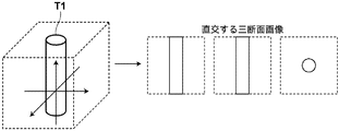
- Patent Document 1 proposes a method of generating three cross-sectional images orthogonal to each other from a three-dimensional image and performing a target tissue detection process based on feature amounts extracted from the three cross-sectional images.
- Patent Document 2 proposes a method of detecting a target tissue from a two-dimensional image by machine learning.
- Non-Patent Document 1 By applying a differential filter to each two-dimensional image (CT image) constituting the three-dimensional image and detecting a position where the pixel value of the CT image changes, a target tissue (for example, a blood vessel) having a linear structure on the region of interest is detected. Etc.) is proposed in Non-Patent Document 1.
- Patent Document 1 sets three cross-sectional images orthogonal to each other from a target tissue as detection target images. For example, when this method is applied to a linear structure, FIG. 17A and FIG. Three cross-sectional images such as 17B are obtained. According to the invention described in Patent Document 1, a cross-sectional image is set by randomly changing three orthogonal axes, and a plurality of detection processes are performed, thereby reducing the total amount of information used for calculation. Detect target tissue.
- An object of the present invention in view of the above circumstances, it is possible to improve detection performance even if the linear tissue or planar tissue is curved, branched, or accompanied by a lesion.
- An object of the present invention is to provide an image processing apparatus and method and a program therefor.
- the weight is set smaller and the tree structure is reconstructed by the minimum spanning tree method.
- the edge information corresponding to the node that is each candidate point and the weight connecting the nodes is the edge information value.
- Non-Patent Document 1 has a strong tendency to simply connect those having a short distance between candidate points (nodes), and correctly connects blood vessel paths when candidate points that cause noise are mixed. There was a problem that could not.
- An object of the present invention in view of the above circumstances, even in a target tissue composed of a linear structure, it is possible to reduce a misconnection and generate a tree structure that more accurately reflects the original linear structure.
- An object of the present invention is to provide an image processing apparatus and method capable of performing the above and a program therefor.
- An image processing apparatus includes a detection region setting unit that sets a detection region in a three-dimensional image obtained by imaging a subject, and a main axis of a target candidate tissue including a linear structure in the detection region. Based on the main axis / normal direction calculation unit for calculating the normal direction of the tissue having a direction or a planar structure, and normalizing the target candidate region including the target candidate tissue based on the main axis direction or the normal direction A normalization processing unit, and a determination unit that calculates a feature amount of the target candidate region subjected to the normalization process, and determines whether or not the target tissue is included in the target candidate region using the calculated feature amount. It is characterized by having.
- the “image processing device” may include an imaging device that generates a three-dimensional image.
- the “main axis / normal direction calculation unit” calculates a main axis direction of a target candidate tissue having a linear structure or a normal direction of a tissue having a planar structure.
- the main axis direction or the normal direction of the target candidate tissue may be calculated by calculating a Hessian matrix for the detection region and analyzing the eigenvalue of the calculated Hessian matrix.
- spindle / normal direction calculation unit determines whether the target candidate tissue has a linear structure or a planar structure, depending on whether the calculated eigenvalue satisfies a predetermined threshold condition. May be determined.
- Detection region refers to a predetermined region including a target region in a three-dimensional image obtained by imaging a subject. For example, when a coronary artery is extracted as a target tissue, a region including a heart region or a region of the region is included. It may be a partial area or the like.
- the discriminating unit is based on the principal axis direction or normal direction of the same type of target tissue with respect to a three-dimensional image prepared in advance including the same type of target tissue as the target tissue.
- Data that has been subjected to normalization processing as teacher data, and by using the teacher data to analyze feature quantities calculated using a machine learning technique, the target tissue May be determined.
- positive teacher data can include data representing a lesioned part such as a curved part, a branched part, a stenosis, a calcification, or a stent placement part in addition to a straight part of the coronary artery.
- a lesioned part such as a curved part, a branched part, a stenosis, a calcification, or a stent placement part in addition to a straight part of the coronary artery.
- the image processing method sets a detection region in a three-dimensional image obtained by imaging a subject, and the main axis direction or planar structure of a target candidate tissue composed of a linear structure in the detection region.
- the normal direction of the tissue consisting of the following is calculated, the target candidate region including the target candidate tissue is normalized based on the main axis direction or the normal direction, and the characteristics of the target candidate region subjected to the normalization processing are normalized
- An amount is calculated, and it is determined whether or not the target tissue is included in the target candidate region using the calculated feature amount.
- the program according to the first aspect of the present invention includes a function for setting a detection area in a three-dimensional image obtained by imaging a subject and a normal direction of a tissue composed of a linear structure or a planar structure in the detection area.
- a function for calculating the main axis direction of the target candidate organization, a function for performing normalization processing on the target candidate region including the target candidate organization based on the main axis direction or the normal direction, and a target subjected to the normalization processing A feature amount of the candidate area is calculated, and the computer is caused to execute a function of determining whether the target tissue is included in the target candidate area using the calculated feature amount.
- An image processing apparatus performs a predetermined detection process on a three-dimensional image obtained by capturing an image of a subject, so that a plurality of candidate points representing a target tissue having a linear structure can be obtained.
- the “candidate point calculation unit” is configured to calculate position information and a principal axis direction of a plurality of candidate points representing a target tissue having a linear structure by performing predetermined detection processing on the three-dimensional image.
- the “candidate point calculation unit” detects a plurality of candidate points having position information and spindle information by calculating a Hessian matrix for a three-dimensional image and analyzing eigenvalues of the calculated Hessian matrix. It may be.
- the “candidate point calculation unit” may detect a candidate point depending on whether or not the eigenvalue satisfies a predetermined threshold condition.
- the “candidate point calculation unit” calculates a feature amount of the normalization processing unit that performs normalization processing on the target region including the target tissue, based on the principal axis direction, You may provide the discrimination
- the “discriminating unit” uses machine learning using data obtained by normalizing a three-dimensional image prepared in advance including a target tissue of the same type as the target tissue based on the main axis direction of the same type of target tissue. It is provided with teacher data obtained by performing the method, and by analyzing the calculated feature value using the teacher data, it is determined whether or not the target region includes a true target tissue You may do.
- the “reconstruction processing unit” performs reconstruction so that a plurality of candidate points are connected using a cost function that is a variable based on the calculated position information and the principal axis direction.
- the “reconstruction processing unit” is a basic unit that connects at least two candidate points among a plurality of candidate points within a certain distance from the position information of each of the two candidate points and connects the two candidate points. Using a cost function on condition that the sum of two acute angles found from the line and the principal axis direction of each of the two candidate points is within a certain angle, it is reconstructed so that multiple candidate points are connected. is there.
- reconstruction may be performed by using the minimum spanning tree method.
- the reconstruction processing unit may use a cost function with the brightness values of two candidate points as variables.
- a “three-dimensional image” is an image composed of voxel data. For example, it is a three-dimensional image composed of a plurality of two-dimensional images. Examples of the two-dimensional image include a radiation image, a CT image, an MRI image, an RI image, and a PET image.
- Target tissue refers to a tissue having a linear structure made up of a predetermined part of a subject represented in a three-dimensional image.
- other linear structures such as coronary arteries, cerebral blood vessels, liver blood vessels, bronchi, pulmonary blood vessels, etc.
- the organization which consists of may be sufficient.
- the image processing method performs a predetermined detection process on a three-dimensional image obtained by capturing an image of a subject, so that a plurality of candidate points representing a target tissue having a linear structure can be obtained.
- the position information and the spindle direction are calculated and reconstructed so that a plurality of candidate points are connected using a cost function that is a variable based on the calculated position information and the spindle direction.
- the program according to the second invention of the present invention performs a predetermined detection process on a three-dimensional image obtained by capturing an image of a subject, thereby position information of a plurality of candidate points representing a target tissue having a linear structure. And a computer that executes a function for reconstructing a plurality of candidate points to be connected using a cost function that is a variable based on the calculated position information and the spindle direction.
- the main axis direction of the target candidate tissue consisting of a linear structure or a planar structure in the detection region or the normal direction of the tissue consisting of the planar structure is calculated, and the main axis Based on the direction or normal direction, normalization processing is performed on the target candidate region including the target candidate organization, the feature amount of the target candidate region subjected to the normalization processing is calculated, and the calculated feature amount is used.
- a plurality of detections representing a target tissue having a linear structure are performed by performing predetermined detection processing on a three-dimensional image obtained by imaging a subject.
- a cost function that is a variable based on the calculated position information and the spindle direction
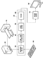
- FIG. 1 is a block diagram showing a preferred embodiment of the image processing apparatus of the present invention.
- the configuration of the image processing apparatus as shown in FIG. 1 is realized by executing a program read in an auxiliary storage device (not shown) on a computer (for example, a personal computer). Further, this program is stored in an information storage medium such as a CD-ROM or distributed via a network such as the Internet and installed in a computer.
- a program read in an auxiliary storage device (not shown) on a computer (for example, a personal computer). Further, this program is stored in an information storage medium such as a CD-ROM or distributed via a network such as the Internet and installed in a computer.
- the image processing apparatus automatically calculates a target tissue represented in a three-dimensional image composed of a plurality of two-dimensional images imaged by, for example, the X-ray CT apparatus 10, and includes a candidate point calculation unit 25,
- the reconstruction processing unit 70 and the like are included.
- An image acquisition unit 20, an input unit 80, a display unit 90, and the like are connected to the image processing apparatus.
- the image acquisition unit 20 acquires a CT image (two-dimensional image) captured by, for example, an imaging apparatus as shown in FIG. 1, for example, the X-ray CT apparatus 10.
- the image acquisition unit 1 may acquire not only a CT image but also a two-dimensional image such as a so-called MRI image, RI image, PET image, X-ray image, and the like.
- the image acquisition part 20 acquires the three-dimensional image comprised by such a some two-dimensional image.
- the input unit 80 is a keyboard, a mouse, or the like.
- the image processing apparatus performs predetermined detection processing on a three-dimensional image obtained by capturing an image of a subject, whereby position information and principal axis directions of a plurality of candidate points representing a target tissue having a linear structure
- a reconstruction processing unit 70 that reconstructs a plurality of candidate points so as to be connected using a cost function that is a variable based on the calculated position information and the principal axis direction. It is to be prepared.
- the candidate point calculation unit 25 includes a detection region setting unit 30, a main axis / normal direction calculation unit 40 (hereinafter, referred to as a main axis direction calculation unit or a main axis calculation unit in some cases), a normalization processing unit 50, and a determination unit. 60.
- the candidate point calculation unit 25 calculates position information and a main axis direction of a plurality of candidate points representing a target tissue having a linear structure by performing a predetermined detection process on the three-dimensional image.
- the candidate point calculation unit 25 calculates the Hessian matrix for the three-dimensional image and analyzes the eigenvalues of the Hessian matrix to calculate the position information and the spindle information of each of the plurality of candidate points. Further, the candidate point calculation unit 25 may detect a candidate point depending on whether or not the calculated eigenvalue satisfies a predetermined threshold condition.
- the candidate point calculation unit 25 sets a detection region setting unit 30 that sets a detection region in the three-dimensional image obtained by the image acquisition unit 20, and a main axis direction that calculates a main axis direction of a target tissue having a linear structure in the detection region.
- the normalization processing unit 50 that performs normalization processing on the target region including the target tissue, and the feature amount of the target region that has been subjected to normalization processing is calculated based on the main axis direction.
- a determination unit 60 that determines whether or not a true target tissue is included in the target region by using the feature amount.
- the detection area setting unit 30 sets a detection area in the three-dimensional image acquired by the image acquisition unit 20.
- the detection area setting unit 30 sets a detection area by executing a detection algorithm, and executes a detection algorithm using, for example, threshold processing and segment division processing.
- a detection algorithm using, for example, threshold processing and segment division processing.
- the heart can be cited as the detection region.
- the detection area setting unit 30 may set the area input by the input unit 80 as a detection area.
- the main axis / normal direction calculation unit 40 calculates the main axis direction of the target candidate tissue having a linear structure in the detection region. For example, in the detection region set by the detection region setting unit 30, the main axis direction of the target candidate tissue having a linear structure or the normal direction of the target candidate tissue having a planar structure is calculated. Calculating the Hessian matrix and analyzing the eigenvalue of the calculated Hessian matrix to calculate the principal axis direction or the normal direction of the target candidate tissue, and the calculated eigenvalue further satisfies a predetermined threshold condition It is determined whether or not the target candidate tissue has a linear structure or a planar structure depending on whether or not the condition is satisfied. This makes it possible to roughly determine whether the structure is a linear structure or a planar structure.
- the determination unit 60 may be configured to more accurately determine whether the structure is a linear structure or a planar structure.
- the normalization processing unit 50 performs normalization processing on the target region including the target tissue based on the main axis direction calculated by the main axis calculation unit 40.
- the determination unit 60 calculates the feature amount of the target region subjected to the normalization process by the normalization processing unit 50, and determines whether the target region includes a true target tissue using the calculated feature amount. To do.
- the determination unit 60 includes, as teacher data, data obtained by performing normalization processing on a three-dimensional image prepared in advance including a target tissue of the same type as the target tissue based on the main axis direction of the same type of target tissue. And determining whether or not a true target tissue is included in the target region by analyzing feature values calculated using a machine learning method using teacher data. Also good.
- positive teacher data can include data representing a lesioned part such as a curved part, a branched part, a stenosis, a calcification, or a stent placement part in addition to a straight part of the coronary artery.
- a machine learning method based on Adaboost which is a method of creating an integrated learning machine, is used as a target tissue detection method.
- the determination unit 60 can be used in the above-described target tissue detection method.
- the target organization sequentially updates the weights when re-sampling known methods such as feature point detection and learning data, and finally assigns the weights to the learning machines to the integrated learning machine.
- a machine learning method based on Adaboost is used.
- the center coordinate of the target tissue and its principal axis direction or the radius in the case of a linear structure are designated, and a cube rotated in the principal axis direction with respect to the center coordinate is set as a region of interest.
- the cube scale is normalized by the radius.
- the positive learning sample for discriminating the coronary artery includes data representing a curved portion of a straight blood vessel, a branch portion of the blood vessel, and a lesion such as stenosis, calcification, and stent placement portion.
- a portion other than the coronary artery is randomly prepared for negative teacher data.
- a combination of the values of n pixel pairs selected at random is used as a feature value, and a positive and negative pattern is discriminated by a machine learning method based on Adaboost.
- a machine learning method based on Adaboost Create a bowl.
- a target tissue is detected, a three-dimensional image is scanned, and cubic regions of various sizes with the pixel of interest at the center are cut out to calculate feature amounts. This is input to the discriminator obtained in the learning stage, and a discriminant value is obtained.
- the feature amount for discrimination is a first-order differential value of each CT value in the X, Y, Z, XY, YZ, and ZX directions in the CT image.
- an absolute value of CT value, a histogram of CT value, a secondary differential value, etc. may be used.
- various other statistical analysis methods and machine learning methods such as a linear discrimination method, a neural network, and a support vector machine can be used as a method for detecting the target tissue.
- the determination unit 60 detects a plurality of positions of the target tissue from the three-dimensional image by the above-described method, and calculates a plurality of the above-described candidate points.
- the display unit 70 is a monitor that displays a two-dimensional image or a three-dimensional image, a CRT screen, or the like.
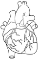
- the image interpreter can visually recognize the detection area by performing volume rendering display of the area determined as the detection area (heart area) on the display unit 70 as shown in FIG. 4A.
- the radiogram interpreter displays the target tissue (blood vessel A1) and the detection region (heart region) as a volume rendering display on the display unit 70 as shown in FIG. Can be visually recognized.
- the determination unit 60 calculates a predetermined point of the target region including the cut out true target tissue as a candidate point.
- the reconstruction processing unit 70 performs reconstruction so that a plurality of candidate points are connected using a cost function that is a variable based on the calculated position information and the principal axis direction.
- the reconstruction processing unit 70 also has a basic line that connects at least two candidate points, and the relationship between at least two candidate points is within a certain distance from the position information of each of the two candidate points.
- a cost function on condition that the sum of two acute angles obtained from the principal axis direction of each of the two candidate points is within a certain angle, and reconstructing a plurality of candidate points to be connected. .
- reconstruction may be performed by using the minimum spanning tree method.
- the reconstruction processing unit 70 may use a cost function with the brightness values of two candidate points as variables.
- FIG. 5 is a series of process flowcharts until the image processing apparatus detects a target tissue having a linear structure in a three-dimensional image.
- a three-dimensional image captured by the X-ray CT apparatus 10 is input to the image acquisition unit 20 (step S1).
- the detection region setting unit 30 detects the heart region by executing the detection algorithm described above.
- the detection region setting unit 30 sets a detection region from the detected heart region (step S2).
- This detection area refers to a predetermined area including a target area in a three-dimensional image obtained by imaging a subject, and may be, for example, an area including a heart area or a partial area thereof. .
- the detection area setting unit 30 generates a Gaussian pyramid by performing multi-resolution conversion of a three-dimensional image in advance so as to detect a target tissue having a linear structure in the detection area.
- the detection region setting unit 30 scans a detection algorithm for each generated Gaussian pyramid to detect a target candidate tissue (for example, a coronary artery) having a linear structure with a different size.
- the detection area setting unit 30 scans the 6A detection area having the Gaussian pyramid structure, and sequentially sets the coordinates for performing the detection process by scanning the 6B detection area and the 6C detection area. By sequentially scanning the multi-resolution image, target tissues of different sizes (for example, coronary arteries) can be detected.
- the main axis direction calculation unit 40 calculates the main axis direction of the target tissue (for example, coronary artery) having a linear structure in the local region centered on the detected coordinates (step S3).
- the main axis direction calculation unit 40 performs eigenvalue analysis of the Hessian matrix in the region including the target candidate tissue, and calculates the main axis direction.
- the Hessian matrix is a matrix having second-order partial differential coefficients as elements, and for a three-dimensional image, it is a 3 ⁇ 3 matrix as shown by the number (1).
- the filter coefficient for obtaining the Hessian matrix is obtained by the number (2).
- ⁇ corresponds to a linear structure having a size to be detected.
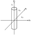
- the eigenvector corresponding to the eigenvalue closest to 0 is the principal axis direction.
- the linear structure is known to have a characteristic that two of the three eigenvalues are large and one is close to zero. Therefore, it is effective to determine the likelihood of a linear structure from the eigenvalues and make a more detailed determination on the remaining candidates. Further, in the case of a planar structure, one of the three eigenvalues has a large absolute value, and two having features close to 0 are determined to be likely to be a planar structure.
- the eigenvalue of the number (1) has a relationship such as the number (3) with respect to the target tissue having a linear structure, for example.
- the normalization processing unit 50 performs normalization processing on the target region including the target tissue based on the main shaft direction calculated by the main shaft direction calculation unit 40 (step S4). As shown in FIG. 8, the normalization processing unit 50 cuts out a normalized image along the calculated principal axis direction. As shown in 8B, the three-dimensional image of the target tissue after the normalization process has a rotation-invariant feature. However, the image processing apparatus does not necessarily have to perform normalization processing, and the determination unit 60 may acquire a feature amount for determination under the same conditions as in the case of normalization and use a machine learning method.
- the determination unit 60 calculates the feature amount of the target region that has been subjected to normalization processing by the normalization processing unit 50, and uses the calculated feature amount to determine whether or not the target region includes a true target tissue. Is determined (step S5).
- the determination unit 60 takes out a feature amount from the target region subjected to normalization processing by the normalization processing unit 50 by the above-described machine learning method or the like, and determines whether or not it is a true target tissue.
- the determination unit 60 When determining that the tissue is a target tissue, the determination unit 60 sets a predetermined point of the target region cut out from the image as a candidate point. The determination is repeated as long as there is a target area to be determined (step S6; YES).
- the coronary artery is identified as an example of the target tissue.
- it can be used to extract other linear structures such as cerebral blood vessels, liver blood vessels, pulmonary blood vessels, and bronchi.
- the image processing apparatus calculates the main axis direction of the target candidate tissue including the linear structure in the detection region or the normal direction of the tissue including the planar structure, and based on the main axis direction or the normal direction.
- the target candidate region including the target candidate organization is subjected to normalization processing, the feature amount of the target candidate region subjected to the normalization processing is calculated, and the target tissue is included in the target candidate region using the calculated feature amount.
- step S6 when the determination of all the target areas is completed and the determination becomes unnecessary (step S6; NO), the relationship between at least two candidate points among the plurality of set candidate points is two candidates.
- the condition is that the basic line connecting the two candidate points is within a certain distance from the position information of each point, and the sum of the basic line and the two acute angles obtained from each principal axis direction is within a certain angle.
- the cost function it is reconstructed whether or not a plurality of candidate points are connected (step S7).
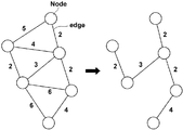
- the reconstruction processing unit 70 reconstructs a plurality of set candidate points by a minimum spanning tree method, and obtains a tree structure of a target tissue that is a coronary artery. At this time, the reconstruction process 70 sets a cost function using edge information between candidate points.
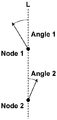
- the cost function sets the weight of edge information between candidate points to be smaller as the distance is shorter. Furthermore, as shown in FIG. 8, the cost function has a constant sum of two acute angles (Angle1 + Angle2) obtained from the principal axis direction of each of the two candidate points with reference to the basic line L connecting the two candidate points (Node1, Node2). Within the angle, the cost function is set so that the weight of the edge information becomes smaller as the sum of the two acute angles is smaller.
- the reconstruction process 70 can reconstruct and connect the candidate points as shown in FIG. 13B from the situation before the candidate points are connected as shown in FIG. 13A. And
- the reconstruction process 70 sets the cost function as in the number (4).
- the cost function is set by using the distance between candidate points, the radius of the blood vessel, the principal axis direction, and the CT values at the candidate points as variables.
- the Gaussian kernel (f) function using the distance between the candidate points of the number (4) and the radius of the blood vessel is a function whose output decreases as the physical distance increases, and is set as shown in FIG. .
- the vertical axis of FIG. 10 is a Gaussian kernel (f) function using the distance between candidate points and the radius of the blood vessel, and the horizontal axis is the physical distance between the two candidate points divided by the blood vessel radius of the candidate point. Value.
- the cost function may be set so that the output of a thick blood vessel is increased even at a relatively long distance.
- the radius (thickness) of the blood vessel represents how much the candidate point is as a multi-resolution image at the time of discrimination. For example, a candidate whose voxel data is found in a resolution image of 1.0 mm has a blood vessel radius of 2.0 mm, and a candidate whose voxel is found in a resolution image of 2.0 mm has a blood vessel radius of 4.0 mm.
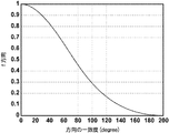
- the Gaussian kernel (f) function using the principal axis direction of the number (4) is such that the directions (Angle 1 and Angle 2) indicated by the two candidate points (Node 1 and Node 2) do not match.
- the basic line L connecting the two candidate points (Node1, Node2) and the sum of the basic line and the two acute angles obtained from the respective principal axis directions (Angle1 + Angle2) are within a certain angle.
- the cost function is set so that the edge weight is smaller as the sum of the two acute angles is smaller.
- shaft of FIG. 11 is a Gaussian kernel (f) function using a principal axis direction, and a horizontal axis shows the coincidence degree of a principal axis direction.
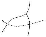
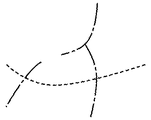
- the reconstruction process 70 Since the reconstruction process 70 generates a tree structure by connecting candidate points to each other using the minimum spanning tree method, the rule is that there is no loop in principle. Therefore, as shown in FIG. 14A, when the vein (dotted line) intersects the artery (dashed line), even if reconstruction is performed, any point in the loop is cut and regenerated as shown in FIG. 14B. Composed. Therefore, by considering the CT value in the cost function, as shown in FIG. 14C, the unconnected edge is on the vein path (dotted line), and the arterial path (chain line) can be correctly reconstructed.
- the Gaussian kernel (f) function using the CT values of the number (4) is set so that the weight becomes smaller as the CT value at the candidate point position is lower.
- the standard is that the CT value of the contrasted coronary artery is about 200 to 400.
- the vertical axis in FIG. 12 represents a Gaussian kernel (f) function using CT values, and the horizontal axis represents the CT values of candidate points (nodes).
- the cost function may be one that sets the heart shape as a weight.
- the least square method is used as shown in FIG.
- An ellipsoid is fitted to the point group of Node4 (candidate points), and the direction connecting the two nodes (candidate points) is calculated as shown in FIG. 15B.
- the Gaussian kernel (f) function using the heart shape calculates the tangential direction of the ellipsoid, and the smaller the difference between these two angles, the lower the cost and the normal direction of the ellipsoid.
- the weight may be set smaller as it is closer to (the difference is closer to 90 degrees).
- the vertical axis in FIG. 16 is a Gaussian kernel (f) function using a heart shape, and the horizontal axis shows the difference between the direction connecting two candidate points (nodes) and the tangential direction of the ellipsoid.
- Gaussian kernel (f) function using a predetermined tissue shape may be set without being limited to the heart shape.
- the reconstruction processing unit 70 uses the minimum spanning tree method to determine whether or not the relationship between at least two candidate points among the detected plurality of candidate points can be connected.
- the target tissue is detected by calculating the relationship between other candidate points.
- the image processing apparatus of the present invention performs a predetermined detection process on a three-dimensional image obtained by imaging a subject, thereby position information of a plurality of candidate points representing a target tissue having a linear structure. And a cost function as a variable based on the calculated position information and the main axis direction, and reconstructing a plurality of candidate points so that noise and noise on the three-dimensional image are calculated. Even if candidate points are mixed, it is possible to accurately detect the target tissue without causing erroneous connection.
Landscapes
- Engineering & Computer Science (AREA)
- Computer Vision & Pattern Recognition (AREA)
- Physics & Mathematics (AREA)
- General Physics & Mathematics (AREA)
- Theoretical Computer Science (AREA)
- Apparatus For Radiation Diagnosis (AREA)
- Image Analysis (AREA)
Abstract
Description



Claims (19)
- 被写体を撮像して得られた三次元画像中の検出領域を設定する検出領域設定部と、
前記検出領域における線状構造からなる対象候補組織の主軸方向または面状構造からなる組織の法線方向を算出する主軸・法線方向算出部と、
前記主軸方向または前記法線方向に基づいて、前記対象候補組織を含む対象候補領域に対して正規化処理を施す正規化処理部と、
前記正規化処理を施された対象候補領域の特徴量を算出し、該算出された特徴量を用いて前記対象候補領域に対象組織が含まれるか否かを判別する判別部とを備えたことを特徴とする画像処理装置。 - 前記主軸・法線方向算出部は、前記検出領域に対してヘッセ行列を算出し、該算出されたヘッセ行列の固有値を解析することにより、前記対象候補組織の主軸方向または法線方向を算出するものであることを特徴とする請求項1記載の画像処理装置。
- 前記主軸・法線方向算出部は、前記算出された固有値が所定の閾値条件を満たすものであるか否かにより、前記対象候補組織が、線状構造または面状構造であるか否かを判別するものであることを特徴とする請求項2記載の画像処理装置。
- 前記判別部は、前記対象組織と同種の対象組織を含む予め用意された三次元画像に対して、前記同種の対象組織の主軸方向または法線方向に基づいて正規化処理を施されたデータを教師データとして備えるものであって、
前記教師データを用いて、マシンラーニング手法を利用して前記算出された特徴量の解析を行うことにより、前記対象候補領域に対象組織が含まれるか否かを判別するものであることを特徴とする請求項1から3いずれか1項記載の画像処理装置。 - 前記対象組織は、冠動脈であることを特徴とする請求項1から4いずれか1項記載の画像処理装置。
- 前記検出領域は、前記被写体の心臓領域を含む領域であることを特徴とする請求項1から5いずれか1項記載の画像処理装置。
- 被写体を撮像して得られた三次元画像中の検出領域を設定し、
前記検出領域における線状構造からなる対象候補組織の主軸方向または面状構造からなる組織の法線方向を算出し、
前記主軸方向または前記法線方向に基づいて、前記対象候補組織を含む対象候補領域に対して正規化処理を施し、
前記正規化処理を施された対象候補領域の特徴量を算出し、該算出された特徴量を用いて前記対象候補領域に対象組織が含まれるか否かを判別することを特徴とする画像処理装置。 - 被写体を撮像して得られた三次元画像中の検出領域を設定する機能と、
前記検出領域における線状構造からなる対象候補組織の主軸方向または面状構造からなる組織の法線方向を算出する機能と、
前記主軸方向または前記法線方向に基づいて、前記対象候補組織を含む対象候補領域に対して正規化処理を施す機能と、
前記正規化処理を施された対象候補領域の特徴量を算出し、該算出された特徴量を用いて前記対象候補領域に対象組織が含まれるか否かを判別する機能とをコンピュータに実現させることを特徴とするプログラム。 - 被写体を撮像して得られた三次元画像に対して所定の検出処理を施すことにより、線状構造からなる対象組織を表す複数の候補点の位置情報と主軸方向を算出する候補点算出部と、
前記算出された位置情報および主軸方向に基づいた変数とするコスト関数を用いて、前記複数の候補点が接続されるように再構築する再構築処理部とを備えたものであることを特徴とする画像処理装置。 - 前記再構築処理部が、前記複数の候補点のうち少なくとも二つの候補点の関係が、該二つの候補点それぞれの位置情報から一定の距離内にあって、かつ前記二つの候補点を結ぶ基本線と、前記二つの候補点それぞれの主軸方向から求まる二つの鋭角の和が一定角度内であることを条件とするコスト関数を用いて、再構築するものであることを特徴とする請求項9記載の画像処理装置。
- 前記候補点算出部は、前記三次元画像に対してヘッセ行列を算出し、該算出されたヘッセ行列の固有値を解析することにより、前記複数の候補点それぞれの位置情報及び主軸情報を算出するものであることを特徴とする請求項9または10記載の画像処理装置。
- 前記候補点算出部は、前記固有値が所定の閾値条件を満たすものであるか否かにより、前記候補点を検出することを特徴とする請求項9から11いずれか1項記載の画像処理装置。
- 前記候補点算出部は、前記主軸方向に基づいて、前記対象組織を含む対象領域に対して正規化処理を施す正規化処理部と、
前記正規化処理を施された対象候補領域の特徴量を算出し、該算出された特徴量を用いて前記対象領域に真の対象組織が含まれるか否かを判別する判別部を備えるものであることを特徴とする請求項9から12いずれか1項記載の画像処理装置。 - 前記判別部は、前記対象組織と同種の対象組織を含む予め用意された三次元画像に対して、前記同種の対象組織の主軸方向に基づいて正規化処理を施されたデータを教師データとして備えるものであって、
前記教師データを用いて、マシンラーニング手法を利用して前記算出された特徴量の解析を行うことにより、前記対象領域に真の対象組織が含まれるか否かを判別するものであることを特徴とする請求項13記載の画像処理装置。 - 前記再構築処理部は、最小全域木手法を用いることにより再構築するものであることを特徴とする請求項9から14いずれか1項記載の画像処理装置。
- 前記再構築処理部が、前記二つの候補点の輝度値を変数としたコスト関数を用いることを特徴とする請求項9から15いずれか1項記載の画像処理装置。
- 前記対象組織は、冠動脈であることを特徴とする請求項9から16いずれか1項記載の画像処理装置。
- 被写体を撮像して得られた三次元画像に対して所定の検出処理を施すことにより、線状構造からなる対象組織を表す複数の候補点の位置情報と主軸方向を算出し、
前記算出された位置情報および主軸方向に基づいた変数とするコスト関数を用いて、前記複数の候補点が接続されるように再構築することを特徴とする画像処理方法。 - 被写体を撮像して得られた三次元画像に対して所定の検出処理を施すことにより、線状構造からなる対象組織を構成する複数の候補点の位置情報と主軸方向を算出する機能と、
前記算出された位置情報および主軸方向に基づいた変数とするコスト関数を用いて、前記複数の候補点が接続されるように再構築する機能とをコンピュータに実現させることを特徴とするプログラム。
Priority Applications (6)
| Application Number | Priority Date | Filing Date | Title |
|---|---|---|---|
| BRPI1004212A BRPI1004212A2 (pt) | 2009-03-03 | 2010-02-23 | aparelho de processamento de imagem, método de processamento de imagem, e programa de processamento de imagem |
| AU2010220015A AU2010220015A1 (en) | 2009-03-03 | 2010-02-23 | Image processing device and method, and program |
| US12/737,623 US8526690B2 (en) | 2009-03-03 | 2010-02-23 | Automatic detection of target tissues formed by linear structures from within three dimensional images |
| CA2732647A CA2732647C (en) | 2009-03-03 | 2010-02-23 | Image processing apparatus, image processing method, and image processing program |
| EP10748460.2A EP2404553B1 (en) | 2009-03-03 | 2010-02-23 | Image processing device and method, and program |
| CN2010800022477A CN102112056A (zh) | 2009-03-03 | 2010-02-23 | 图像处理装置、图像处理方法和图像处理程序 |
Applications Claiming Priority (4)
| Application Number | Priority Date | Filing Date | Title |
|---|---|---|---|
| JP2009048679A JP4709290B2 (ja) | 2009-03-03 | 2009-03-03 | 画像処理装置および方法並びにプログラム |
| JP2009-048679 | 2009-03-03 | ||
| JP2009-069895 | 2009-03-23 | ||
| JP2009069895A JP4717935B2 (ja) | 2009-03-23 | 2009-03-23 | 画像処理装置および方法並びにプログラム |
Publications (1)
| Publication Number | Publication Date |
|---|---|
| WO2010100858A1 true WO2010100858A1 (ja) | 2010-09-10 |
Family
ID=42709428
Family Applications (1)
| Application Number | Title | Priority Date | Filing Date |
|---|---|---|---|
| PCT/JP2010/001191 Ceased WO2010100858A1 (ja) | 2009-03-03 | 2010-02-23 | 画像処理装置および方法並びにプログラム |
Country Status (7)
| Country | Link |
|---|---|
| US (1) | US8526690B2 (ja) |
| EP (1) | EP2404553B1 (ja) |
| CN (1) | CN102112056A (ja) |
| AU (1) | AU2010220015A1 (ja) |
| BR (1) | BRPI1004212A2 (ja) |
| CA (1) | CA2732647C (ja) |
| WO (1) | WO2010100858A1 (ja) |
Cited By (1)
| Publication number | Priority date | Publication date | Assignee | Title |
|---|---|---|---|---|
| CN104978725A (zh) * | 2014-04-03 | 2015-10-14 | 上海联影医疗科技有限公司 | 一种冠状动脉分割方法和装置 |
Families Citing this family (26)
| Publication number | Priority date | Publication date | Assignee | Title |
|---|---|---|---|---|
| CN102004925B (zh) * | 2010-11-09 | 2012-08-29 | 无锡中星微电子有限公司 | 物体分类模型的训练方法及利用该模型的识别方法 |
| WO2012078636A1 (en) | 2010-12-07 | 2012-06-14 | University Of Iowa Research Foundation | Optimal, user-friendly, object background separation |
| US12367578B2 (en) | 2010-12-07 | 2025-07-22 | University Of Iowa Research Foundation | Diagnosis of a disease condition using an automated diagnostic model |
| EP2665406B1 (en) | 2011-01-20 | 2021-03-10 | University of Iowa Research Foundation | Automated determination of arteriovenous ratio in images of blood vessels |
| JP5263995B2 (ja) | 2011-03-18 | 2013-08-14 | 富士フイルム株式会社 | ネットワーク構築装置および方法ならびにプログラム |
| JP2012223338A (ja) | 2011-04-19 | 2012-11-15 | Fujifilm Corp | 木構造作成装置および方法ならびにプログラム |
| JP5701138B2 (ja) | 2011-04-19 | 2015-04-15 | 富士フイルム株式会社 | 医用画像処理装置および方法、並びにプログラム |
| JP5391229B2 (ja) | 2011-04-27 | 2014-01-15 | 富士フイルム株式会社 | 木構造抽出装置および方法ならびにプログラム |
| US8867822B2 (en) * | 2011-10-14 | 2014-10-21 | Fujifilm Corporation | Model-based coronary artery calcium scoring |
| JP5748636B2 (ja) * | 2011-10-26 | 2015-07-15 | 富士フイルム株式会社 | 画像処理装置および方法並びにプログラム |
| US9545196B2 (en) | 2012-05-04 | 2017-01-17 | University Of Iowa Research Foundation | Automated assessment of glaucoma loss from optical coherence tomography |
| JP5946127B2 (ja) | 2012-05-11 | 2016-07-05 | 富士通株式会社 | シミュレーション方法、シミュレーション装置、およびシミュレーションプログラム |
| JP5777070B2 (ja) * | 2012-09-14 | 2015-09-09 | 富士フイルム株式会社 | 領域抽出装置、領域抽出方法および領域抽出プログラム |
| JP5833994B2 (ja) | 2012-09-20 | 2015-12-16 | 富士フイルム株式会社 | 画像処理装置および方法ならびにプログラム |
| US9020982B2 (en) * | 2012-10-15 | 2015-04-28 | Qualcomm Incorporated | Detection of planar targets under steep angles |
| WO2014143891A1 (en) * | 2013-03-15 | 2014-09-18 | University Of Iowa Research Foundation | Automated separation of binary overlapping trees |
| WO2014168350A1 (ko) | 2013-04-10 | 2014-10-16 | 재단법인 아산사회복지재단 | 폐동맥과 폐정맥을 구분하는 방법 및 이를 이용한 혈관의 정량화 방법 |
| JP6358590B2 (ja) | 2013-08-09 | 2018-07-18 | 富士通株式会社 | 血管データ生成装置、血管データ生成方法、および血管データ生成プログラム |
| US10410355B2 (en) | 2014-03-21 | 2019-09-10 | U.S. Department Of Veterans Affairs | Methods and systems for image analysis using non-euclidean deformed graphs |
| JP6539736B2 (ja) * | 2014-11-14 | 2019-07-03 | シーメンス ヘルスケア ゲゼルシヤフト ミツト ベシユレンクテル ハフツング | 純粋幾何学的機械学習に基づいて血流予備量比を求める方法及びシステム |
| US10115194B2 (en) | 2015-04-06 | 2018-10-30 | IDx, LLC | Systems and methods for feature detection in retinal images |
| CN112037194B (zh) * | 2020-08-31 | 2023-04-07 | 中冶赛迪信息技术(重庆)有限公司 | 一种冷床乱钢检测方法、系统、设备及介质 |
| JP2022095024A (ja) * | 2020-12-16 | 2022-06-28 | キヤノン株式会社 | 学習データ生成装置、学習データ生成方法及びコンピュータプログラム |
| CN113962958B (zh) * | 2021-10-21 | 2023-05-05 | 四川大学华西医院 | 一种征象检测方法及装置 |
| JP7847492B2 (ja) * | 2022-06-29 | 2026-04-17 | 富士フイルム株式会社 | 画像処理装置、方法およびプログラム |
| CN115930704B (zh) * | 2022-12-15 | 2025-07-01 | 中国人民解放军军事科学院国防工程研究院工程防护研究所 | 一种用于阵列式光幕靶的多目标时空联合自动筛选方法 |
Citations (4)
| Publication number | Priority date | Publication date | Assignee | Title |
|---|---|---|---|---|
| JP2004230086A (ja) * | 2003-01-31 | 2004-08-19 | Toshiba Corp | 画像処理装置、画像データ処理方法、及びプログラム |
| JP2006346094A (ja) * | 2005-06-15 | 2006-12-28 | Konica Minolta Medical & Graphic Inc | 検出情報の出力方法及び医用画像処理システム |
| JP2007307358A (ja) | 2006-04-17 | 2007-11-29 | Fujifilm Corp | 画像処理方法および装置ならびにプログラム |
| US7346209B2 (en) | 2002-09-30 | 2008-03-18 | The Board Of Trustees Of The Leland Stanford Junior University | Three-dimensional pattern recognition method to detect shapes in medical images |
Family Cites Families (4)
| Publication number | Priority date | Publication date | Assignee | Title |
|---|---|---|---|---|
| US7639855B2 (en) * | 2003-04-02 | 2009-12-29 | Ziosoft, Inc. | Medical image processing apparatus, and medical image processing method |
| JP4447005B2 (ja) * | 2003-04-24 | 2010-04-07 | コーニンクレッカ フィリップス エレクトロニクス エヌ ヴィ | コンピュータ断層撮影アンジオグラフィにおける領域描写方法及び装置 |
| WO2006126384A1 (ja) * | 2005-05-23 | 2006-11-30 | Konica Minolta Medical & Graphic, Inc. | 異常陰影候補の表示方法及び医用画像処理システム |
| US7894664B2 (en) * | 2006-03-22 | 2011-02-22 | University Of Washington | Conditional shape model for image processing |
-
2010
- 2010-02-23 CA CA2732647A patent/CA2732647C/en not_active Expired - Fee Related
- 2010-02-23 BR BRPI1004212A patent/BRPI1004212A2/pt not_active IP Right Cessation
- 2010-02-23 WO PCT/JP2010/001191 patent/WO2010100858A1/ja not_active Ceased
- 2010-02-23 CN CN2010800022477A patent/CN102112056A/zh active Pending
- 2010-02-23 EP EP10748460.2A patent/EP2404553B1/en not_active Not-in-force
- 2010-02-23 AU AU2010220015A patent/AU2010220015A1/en not_active Abandoned
- 2010-02-23 US US12/737,623 patent/US8526690B2/en active Active
Patent Citations (4)
| Publication number | Priority date | Publication date | Assignee | Title |
|---|---|---|---|---|
| US7346209B2 (en) | 2002-09-30 | 2008-03-18 | The Board Of Trustees Of The Leland Stanford Junior University | Three-dimensional pattern recognition method to detect shapes in medical images |
| JP2004230086A (ja) * | 2003-01-31 | 2004-08-19 | Toshiba Corp | 画像処理装置、画像データ処理方法、及びプログラム |
| JP2006346094A (ja) * | 2005-06-15 | 2006-12-28 | Konica Minolta Medical & Graphic Inc | 検出情報の出力方法及び医用画像処理システム |
| JP2007307358A (ja) | 2006-04-17 | 2007-11-29 | Fujifilm Corp | 画像処理方法および装置ならびにプログラム |
Non-Patent Citations (3)
| Title |
|---|
| ANDRZEJ SZYMCZAK ET AL.: "Coronary Vessel Trees from 3D Imagery: A Topological Approach", MEDICAL IMAGE ANALYSIS, vol. 10, no. 4, 2006, pages 548 - 559 |
| HIDENORI SHIKATA ET AL.: "Bimansei Hai Shikkan Gazo kara no Hai Kekkan Chushutsu Algorithm no Kento", IEICE TECHNICAL REPORT, vol. 104, no. 580, 15 January 2005 (2005-01-15), pages 31 - 36, XP008141744 * |
| See also references of EP2404553A4 |
Cited By (1)
| Publication number | Priority date | Publication date | Assignee | Title |
|---|---|---|---|---|
| CN104978725A (zh) * | 2014-04-03 | 2015-10-14 | 上海联影医疗科技有限公司 | 一种冠状动脉分割方法和装置 |
Also Published As
| Publication number | Publication date |
|---|---|
| EP2404553A4 (en) | 2013-03-13 |
| CA2732647C (en) | 2014-04-29 |
| US20110135172A1 (en) | 2011-06-09 |
| EP2404553B1 (en) | 2015-06-24 |
| EP2404553A1 (en) | 2012-01-11 |
| CN102112056A (zh) | 2011-06-29 |
| CA2732647A1 (en) | 2010-09-10 |
| AU2010220015A1 (en) | 2010-09-10 |
| US8526690B2 (en) | 2013-09-03 |
| AU2010220015A2 (en) | 2011-03-10 |
| BRPI1004212A2 (pt) | 2016-02-23 |
Similar Documents
| Publication | Publication Date | Title |
|---|---|---|
| JP4717935B2 (ja) | 画像処理装置および方法並びにプログラム | |
| WO2010100858A1 (ja) | 画像処理装置および方法並びにプログラム | |
| JP4999163B2 (ja) | 画像処理方法および装置ならびにプログラム | |
| Azemin et al. | Robust methodology for fractal analysis of the retinal vasculature | |
| US10210612B2 (en) | Method and system for machine learning based estimation of anisotropic vessel orientation tensor | |
| CN109124662B (zh) | 肋骨中心线检测装置及方法 | |
| JP5011426B2 (ja) | 画像診断支援装置、方法及びプログラム | |
| JP6570145B2 (ja) | 画像を処理する方法、プログラム、代替的な投影を構築する方法および装置 | |
| JP5037705B2 (ja) | 画像処理装置および方法並びにプログラム | |
| JP4964171B2 (ja) | 対象領域抽出方法および装置ならびにプログラム | |
| KR20150047315A (ko) | 컴퓨터 보조 진단 방법 및 장치 | |
| JP6273291B2 (ja) | 画像処理装置および方法 | |
| CN102458225A (zh) | 图像处理设备及其控制方法和计算机程序 | |
| Kitamura et al. | Automatic coronary extraction by supervised detection and shape matching | |
| JP2005526583A (ja) | 車輪状投影分析を用いた肺結節検出 | |
| JP6458166B2 (ja) | 医用画像処理方法及び装置及びシステム及びプログラム | |
| Pock et al. | Multiscale medialness for robust segmentation of 3d tubular structures | |
| Jerman et al. | Computer-aided detection and quantification of intracranial aneurysms | |
| JP5364009B2 (ja) | 画像生成装置、画像生成方法、及びそのプログラム | |
| JP4709290B2 (ja) | 画像処理装置および方法並びにプログラム | |
| Truc et al. | A new approach to vessel enhancement in angiography images | |
| KR102789401B1 (ko) | 심비대증 평가를 위한 의료 영상 분석 방법 및 장치 | |
| Stetten et al. | Automated segmentation of the right heart using an optimized shells and spheres algorithm | |
| KR20240080580A (ko) | 지방간 질환 자동 진단을 위한 3d 간 ct 영상의 분할 및 강체 정합 장치 및 방법 | |
| Pan et al. | 3D liver vessel reconstruction from CT images |
Legal Events
| Date | Code | Title | Description |
|---|---|---|---|
| WWE | Wipo information: entry into national phase |
Ref document number: 201080002247.7 Country of ref document: CN |
|
| 121 | Ep: the epo has been informed by wipo that ep was designated in this application |
Ref document number: 10748460 Country of ref document: EP Kind code of ref document: A1 |
|
| ENP | Entry into the national phase |
Ref document number: 2732647 Country of ref document: CA |
|
| WWE | Wipo information: entry into national phase |
Ref document number: 12737623 Country of ref document: US Ref document number: 2010748460 Country of ref document: EP |
|
| WWE | Wipo information: entry into national phase |
Ref document number: 1062/CHENP/2011 Country of ref document: IN |
|
| WWE | Wipo information: entry into national phase |
Ref document number: 2010220015 Country of ref document: AU |
|
| ENP | Entry into the national phase |
Ref document number: 2010220015 Country of ref document: AU Date of ref document: 20100223 Kind code of ref document: A |
|
| NENP | Non-entry into the national phase |
Ref country code: DE |
|
| ENP | Entry into the national phase |
Ref document number: PI1004212 Country of ref document: BR Kind code of ref document: A2 Effective date: 20110222 |