WO2010101013A1 - 異常検知および車両追跡装置 - Google Patents
異常検知および車両追跡装置 Download PDFInfo
- Publication number
- WO2010101013A1 WO2010101013A1 PCT/JP2010/052063 JP2010052063W WO2010101013A1 WO 2010101013 A1 WO2010101013 A1 WO 2010101013A1 JP 2010052063 W JP2010052063 W JP 2010052063W WO 2010101013 A1 WO2010101013 A1 WO 2010101013A1
- Authority
- WO
- WIPO (PCT)
- Prior art keywords
- vehicle
- abnormality detection
- abnormal state
- vibration
- battery
- Prior art date
- Legal status (The legal status is an assumption and is not a legal conclusion. Google has not performed a legal analysis and makes no representation as to the accuracy of the status listed.)
- Ceased
Links
Images


Classifications
-
- B—PERFORMING OPERATIONS; TRANSPORTING
- B60—VEHICLES IN GENERAL
- B60R—VEHICLES, VEHICLE FITTINGS, OR VEHICLE PARTS, NOT OTHERWISE PROVIDED FOR
- B60R25/00—Fittings or systems for preventing or indicating unauthorised use or theft of vehicles
- B60R25/01—Fittings or systems for preventing or indicating unauthorised use or theft of vehicles operating on vehicle systems or fittings, e.g. on doors, seats or windscreens
- B60R25/04—Fittings or systems for preventing or indicating unauthorised use or theft of vehicles operating on vehicle systems or fittings, e.g. on doors, seats or windscreens operating on the propulsion system, e.g. engine or drive motor
-
- B—PERFORMING OPERATIONS; TRANSPORTING
- B60—VEHICLES IN GENERAL
- B60R—VEHICLES, VEHICLE FITTINGS, OR VEHICLE PARTS, NOT OTHERWISE PROVIDED FOR
- B60R25/00—Fittings or systems for preventing or indicating unauthorised use or theft of vehicles
- B60R25/10—Fittings or systems for preventing or indicating unauthorised use or theft of vehicles actuating a signalling device
- B60R25/102—Fittings or systems for preventing or indicating unauthorised use or theft of vehicles actuating a signalling device a signal being sent to a remote location, e.g. a radio signal being transmitted to a police station, a security company or the owner
- B60R25/1025—Fittings or systems for preventing or indicating unauthorised use or theft of vehicles actuating a signalling device a signal being sent to a remote location, e.g. a radio signal being transmitted to a police station, a security company or the owner preventing jamming or interference of said signal
-
- B—PERFORMING OPERATIONS; TRANSPORTING
- B60—VEHICLES IN GENERAL
- B60R—VEHICLES, VEHICLE FITTINGS, OR VEHICLE PARTS, NOT OTHERWISE PROVIDED FOR
- B60R25/00—Fittings or systems for preventing or indicating unauthorised use or theft of vehicles
- B60R25/30—Detection related to theft or to other events relevant to anti-theft systems
- B60R25/33—Detection related to theft or to other events relevant to anti-theft systems of global position, e.g. by providing GPS coordinates
-
- B—PERFORMING OPERATIONS; TRANSPORTING
- B60—VEHICLES IN GENERAL
- B60R—VEHICLES, VEHICLE FITTINGS, OR VEHICLE PARTS, NOT OTHERWISE PROVIDED FOR
- B60R2325/00—Indexing scheme relating to vehicle anti-theft devices
- B60R2325/30—Vehicles applying the vehicle anti-theft devices
- B60R2325/306—Motorcycles
Definitions
- the present invention relates to an anomaly detection and vehicle tracking device, and more particularly to an anomaly detection and vehicle tracking device that generates an alarm when vibrations applied to a vehicle body are detected while a passenger is getting off.
- Patent Document 1 when a code signal in a transmission radio wave from a portable transmitter is correctly verified, a standby current for allowing the code signal to be always received does not flow in an abnormality detection device that releases a warning state.
- a configuration is disclosed in which current consumption for code signal reception and verification is allowed to flow for a certain period of time after a predetermined switch is operated, thereby reducing battery consumption while the vehicle is stopped.
- an abnormality detection device that determines that an abnormality has occurred in an article based on an output value of a vibration sensor attached to a predetermined article and issues an alarm or the like.
- Patent Document 2 in an abnormality detection device attached to a portable article such as a personal computer, the movement distance of the article is estimated based on the output interval of the signal output from the vibration sensor, and the movement distance exceeds a predetermined value. In such a case, a configuration is disclosed in which it is determined that the state is abnormal.
- the abnormality detection device that has an internal power supply that is independent from the in-vehicle battery and that can be continuously driven even when the in-vehicle battery is removed when the vehicle is stopped, the abnormal voltage drop when the in-vehicle battery is removed It is possible to determine that there is an abnormality in the vehicle and activate the warning means.
- the vehicle equipped with such an abnormality detection device is a vehicle having a kick starter or a manual mission type vehicle capable of being pushed, the engine is started even when the on-board battery has run out of the battery. I can do it.
- the above-described abnormality detection device may determine that the vehicle-mounted battery is in an abnormal state after the user has just turned off the ignition switch and activate the warning means.
- the object of the present invention is to solve the above-described problems of the prior art, and when the vehicle-mounted battery is removed, the battery after running when the vehicle-mounted battery is running up while allowing the abnormality to be detected / alarmed.
- An object of the present invention is to provide an abnormality detection and vehicle tracking device that can prevent erroneous detection of an abnormality.
- the abnormality detection device described in Patent Document 2 is a system that determines an abnormality based on the movement distance of an article from the time when vibration is detected. In the case of, it was not suitable.
- the vehicle is preferably a system that can detect anomalies before moving and has few false detections.
- An object of the present invention is to solve the above-described problems of the prior art and provide an abnormality detection and vehicle tracking device with few malfunctions and false detections while improving the certainty of abnormal state determination based on vibration applied to the vehicle body. It is in.
- the present invention detects an abnormal state of a vehicle based on a battery voltage of an in-vehicle battery detected by a voltage sensor, and detects abnormality in the abnormality detection and vehicle tracking device having a vehicle tracking function. And an internal power source for operating the vehicle tracking device, a battery voltage detecting means for detecting the battery voltage, and an operation mode of the abnormality detecting and vehicle tracking device when at least warning means are activated when the vehicle is determined to be in an abnormal state.
- An operation mode switching means for switching to an alarm theft mode, wherein the operation mode switching means switches the operation mode according to the degree of decrease in the battery voltage when the ignition switch for switching on / off of the main power supply of the vehicle is turned off.
- the first feature is that the mode is switched to the alarm theft mode.
- the operation mode switching means is in an abnormal state when the battery voltage falls below a predetermined voltage within a predetermined time after the ignition switch for switching on / off of the main power supply of the vehicle is turned off. On the other hand, if the battery voltage is equal to or lower than the predetermined voltage after the predetermined time has elapsed and the rate of decrease in the battery voltage is equal to or higher than the predetermined value, it is determined that the vehicle is in an abnormal state.
- the second feature is that the operation mode is switched to the alarm theft mode.
- the operation mode switching means may determine that the vehicle is not in an abnormal state when the battery voltage becomes equal to or lower than a predetermined voltage after the predetermined time has elapsed and the battery voltage decrease rate is less than a predetermined value.
- a third feature is that the operation mode switching is not executed after determination.
- the fourth feature is that the abnormality detection and vehicle tracking device includes an internal power source that continuously drives the abnormality detection and vehicle tracking device when the battery voltage of the in-vehicle battery becomes equal to or lower than a predetermined voltage. is there.
- the abnormality detecting means including a vibration sensor for detecting vibration applied to the vehicle detects an abnormal state of the vehicle, has a vehicle tracking function, and measures the vibration detection interval and the number of detection times, And an abnormal state determination unit that determines an abnormal state of the vehicle based on an output signal of the vibration sensor, wherein the abnormal state determination unit is a predetermined combination of the vibration detection interval and the number of detections.
- a fifth feature is that a plurality of patterns are stored and an abnormal state of the vehicle is determined based on the patterns.
- an in-vehicle telephone capable of wireless communication via a public telephone line, and when the abnormal state determination means determines that it is in an abnormal state, the external state is notified to the outside using the in-vehicle telephone.
- the abnormal state determination means determines that it is in an abnormal state
- the external state is notified to the outside using the in-vehicle telephone.
- the vibration having a magnitude greater than or equal to the predetermined value is first detected, the vibration having the magnitude greater than or equal to the predetermined value is detected once within 5 minutes.
- a seventh feature in that it is decided to be performed.
- a vibration having a magnitude greater than or equal to a predetermined value is detected once within 5 minutes to 10 minutes, There is an eighth feature in that it is repeated twice.
- a ninth feature is that the predetermined pattern is detected continuously for vibrations having a magnitude of a predetermined value or more for 10 minutes or more.
- the operation mode switching means switches the operation mode to the alarm theft mode in accordance with the degree of battery voltage drop when the ignition switch for switching on / off of the main power supply of the vehicle is turned off.
- the internal power supply of the vehicle tracking device can detect and warn when an in-vehicle battery is removed, and whether the system issues an alarm according to the degree of battery voltage drop when the ignition switch is turned off. Therefore, it is possible to prevent an unnecessary alarm without detecting an abnormality due to a decrease in the battery voltage when the ignition is turned off after the battery is running.
- the operation mode switching means detects that the vehicle is in an abnormal state when the battery voltage becomes equal to or lower than the predetermined voltage within a predetermined time after the ignition switch for switching on / off of the main power supply of the vehicle is turned off.
- the battery voltage becomes equal to or lower than the predetermined voltage after a predetermined time has passed and the rate of decrease in the battery voltage is equal to or higher than the predetermined value, it is determined that the vehicle is in an abnormal state. Since the operation mode is switched to the alarm theft mode, is the ignition switch turned off with the on-board battery running out of battery by setting the predetermined time to a very short time (for example, 20 seconds)? Alternatively, it is possible to execute different control by determining whether the vehicle-mounted battery is in an abnormal state while being stopped.
- the operation mode switching means is configured such that the vehicle is not in an abnormal state when the battery voltage becomes equal to or lower than the predetermined voltage after a predetermined time has elapsed and the battery voltage decrease rate is less than the predetermined value. Therefore, it is possible to prevent the battery from being erroneously determined to be in an abnormal state when the battery voltage is slowly decreased due to natural discharge after the ignition switch is turned off.
- the internal power source for continuously driving the abnormality detection and the vehicle tracking device when the battery voltage of the in-vehicle battery becomes equal to or lower than a predetermined voltage is provided, Even when the vehicle-mounted battery is removed while the vehicle is stopped, the abnormality detection and vehicle tracking device can be continuously driven.
- a plurality of predetermined patterns composed of combinations of vibration detection intervals and the number of detections are stored, and an abnormal state of the vehicle is determined based on the patterns.
- the system can prevent the system from malfunctioning only by detecting a temporary vibration when it touches the vehicle body, etc. Can also be increased.
- an in-vehicle telephone capable of wireless communication via a public telephone line and an abnormal state using the in-vehicle telephone when it is determined to be abnormal by the abnormal state determination means. Since the communication control unit that can be notified to the outside is provided, for example, when it is determined to be in an abnormal state, it is possible to notify the user's mobile phone, personal computer, or the like that it is in an abnormal state. Further, if the position information by the in-vehicle GPS is notified at the time of communication, it is possible to know the movement history before and after reaching the abnormal state. Furthermore, if the vibration pattern that has been determined to be an abnormal state is notified, the user or the like can guess the cause.
- a vibration having a magnitude greater than or equal to a predetermined value is detected once within 5 minutes after a vibration having a magnitude greater than or equal to a predetermined value is first detected. Is repeated three times, so that, for example, even when an exterior part or a battery is removed, the abnormal state is reliably detected based on vibrations generated by continuing the removal operation. It becomes possible.
- a vibration having a magnitude greater than or equal to a predetermined value is detected once within 5 to 10 minutes. Since it is decided to be repeated twice, for example, even when the chain lock that connects the vehicle and the pillar, the bar lock that makes the wheel unrotatable, etc. is released, the work is continued. It is possible to reliably detect the abnormal state based on the generated vibration.
- the predetermined pattern is continuously detected with vibrations having a magnitude greater than or equal to a predetermined value for 10 minutes or more.
- the vehicle is immediately loaded on a truck for transportation. Even in the case where the operation is performed, it is possible to reliably detect the abnormal state based on the traveling vibration during transportation.
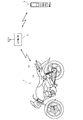
- FIG. 1 is a conceptual diagram showing a communication system of an abnormality detection and vehicle tracking device (hereinafter also referred to as an abnormality detection device) according to an embodiment of the present invention.
- the motorcycle 1 is provided with an abnormality detection device 10 that detects an abnormal state of the vehicle and issues a warning.
- an abnormality detection device 10 determines that an abnormality has occurred in the vehicle, and the vehicle horn or lamp It is comprised so that a warning etc. may be actuated.
- the abnormality detection device 10 includes an in-vehicle telephone (see FIG. 2) that can communicate with the public telephone office 2. As a result, it is possible to make a call from the telephone 3 to the abnormality detection apparatus 10 via the public telephone station 2.
- the telephone 3 may be a mobile phone or a fixed telephone as long as it can access the public telephone station 2.
- GSM Global System for Mobile Communications
- GSM Global System for Mobile Communications
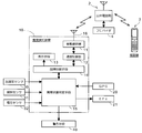
- FIG. 2 is a block diagram showing the configuration of the abnormality detection apparatus 10 and its peripheral devices according to this embodiment.
- the abnormality detection device 10 is, for example, a control device that is covered with a resin case of about 100 mm ⁇ 100 mm ⁇ 20 mm and does not have an operation means such as a switch, for example, a lower part of a motorcycle seat, a lower part of a fuel tank, etc. It is placed in a position where it is difficult for third parties to access.
- the abnormality detection device 10 includes a vehicle-mounted telephone 11 having a transmission / reception antenna 16 for communicating with the public telephone office 2, a communication control unit 12 that analyzes transmission / reception signals by the vehicle-mounted telephone 11, and failure detection of the abnormality detection device 10.
- the in-vehicle telephone 11 may be provided outside the abnormality detection device 10. Further, the communication control unit 12 can be set so as to deny access from other than a predetermined telephone registered in advance.
- the vehicle owner needs to make a communication contract with the provider 4. Whether or not to make a communication contract with the provider 4 can be arbitrarily selected by the owner of the vehicle. Even when the user does not have a communication contract with the provider 4, the abnormality detection device 10 can be used as a normal abnormality detection device that operates the warning means 40 based on vibrations applied to the vehicle body.
- the in-vehicle telephone 11 it is assumed that all have a communication contract with the provider 4.
- the abnormal state determination means 15 includes an acceleration sensor 30 that detects vibrations applied to the vehicle body, a tilt sensor 31 that detects the front and rear, left and right tilt angles of the vehicle body, battery voltage for monitoring access to the power supply circuit, and the like. An output signal from the voltage sensor 32 that detects a change is input. For example, the abnormal state determination unit 15 determines that the vehicle is in an abnormal state when at least one output signal of various sensors exceeds a predetermined value.
- the abnormality detection device 10 is configured to be able to transmit to the telephone 3 such as a user via the in-vehicle telephone 11 that an abnormal condition has been detected. At this time, the time when the abnormal state is detected, the type of the activated sensor, and the like can be displayed on the display as the display means of the telephone 3.
- a GPS (Global Positioning System) 20 is connected to the abnormal state determination means 15.
- the GPS 20 is used for the operation of the in-vehicle navigation system during normal driving of the vehicle.
- the abnormality detection device 10 when an abnormality occurs, the current position of the vehicle and the movement from the occurrence of the abnormality are detected. It is configured such that it can be used for a vehicle tracking function for transmitting a history or the like to the telephone 3 or the like via the in-vehicle telephone 11.
- an EFI (electronic control fuel injection device) 21 as an engine control device connected to the abnormal state determination means 15 is configured to be able to stop its drive in response to a command from the abnormal state determination means 15.
- the EFI 21 can be automatically stopped so that the vehicle cannot travel.
- the stop of the EFI 21 can be arbitrarily executed by operating the telephone 3.
- the engine control device controlled by a command from the abnormal state determination means 15 may be an ignition device for a spark plug, various actuators, or the like.
- the abnormality detection device 10 diagnoses whether or not the abnormality detection device 10 is functioning normally by the failure diagnosis means 14, that is, executes a self-failure diagnosis (diagnosis) of the abnormality detection device 10. Is possible.
- the failure diagnosis unit 14 can detect, for example, a state where it cannot be determined as abnormal even if various sensors output signals exceeding a predetermined value due to a malfunction of the abnormal state determination unit 15. Further, the failure diagnosing means 14 can diagnose a state in which output signals from various sensors are not normally input, failure of various sensors themselves, and the like. When such a failure is detected, the failure diagnosing unit 14 is set to display the type of failure, a countermeasure, and the like on the display unit 13.
- a vehicle mechanic or the like can perform a failure diagnosis of the abnormality detection device 10 by calling the abnormality detection device 10 from the telephone 3 and know the diagnosis result by the display means 13. It can.
- a light emitting diode (LED), a liquid crystal screen, or the like can be applied to the display means 13.
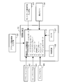
- FIG. 3 is a time chart showing a flow when executing the self-failure diagnosis process of the abnormality detection device 10 using the telephone 3.
- step S10 when a vehicle mechanic or the like calls the abnormality detection device 10 from the telephone 3, the vehicle-mounted telephone 11 of the abnormality detection device 10 receives this in step S11.
- step S12 reception completion is displayed on the display means 13. Thereby, the maintenance person etc. can confirm visually that the telephone line was connected.
- the procedure for making a call in step S10 can be executed by dialing a telephone number unique to the vehicle-mounted telephone 11 from a fixed telephone, a mobile phone or the like.
- a diagnostic item number (for example, 1 to 5) is input to the telephone 3.
- This diagnosis item can be constituted by contents such as whether there is no short circuit in the constituent circuit of the abnormality detection apparatus 10 or whether various sensors are functioning normally.
- the input diagnostic item is received by the in-vehicle telephone 11, and in step S22, the input diagnostic item is displayed on the display means 13.
- the display means 13 displays that a failure diagnosis is to be performed.
- a failure diagnosis instruction signal for starting a failure diagnosis is output from the communication control unit 12, and the selected diagnosis item is displayed.
- the failure diagnosis unit 14 executes the failure diagnosis.
- the abnormality detection device 10 it is possible to perform failure diagnosis of the abnormality detection device 10 by operating the telephone 3. Normally, if the abnormality detection device 10 is provided with a self-diagnosis function so that a dedicated device for performing failure diagnosis is not required, the failure diagnosis mode in which the function of the abnormality detection device is temporarily suspended from the normal abnormality detection mode state. However, according to the abnormality detection device 10 according to the present embodiment, there is no need to provide an input means that can be operated by a third party, so that an easy method can be used. A failure diagnosis of the abnormality detection device can be executed, and a high abnormality detection effect of the abnormality detection device can be maintained.
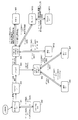
- FIG. 4 is a circuit diagram of the abnormality detection device and its peripheral devices according to the present embodiment.
- the same reference numerals as those described above denote the same or equivalent parts.
- the CPU 50 as the central processing unit of the abnormality detection apparatus 10 includes abnormality determination means, failure diagnosis means, and the like as shown in FIG.
- an LED (light emitting diode) connected to the CPU 50 is used as the display unit 13.
- An internal power supply 66 is connected to the CPU 50.
- the internal power supply 66 is provided to operate various sensors even when the in-vehicle battery 63 is removed, to drive the warning means 40 based on an output signal of the sensor, or to enable communication by the in-vehicle telephone 11. ing. If the in-vehicle battery 63 is connected, the CPU 50 is driven by the electric power of the in-vehicle battery 63, and the internal power supply 66 is not used. In this normal time, the internal power supply 10 is maintained in a fully charged state by the power supplied from the in-vehicle battery 63, and is set to be switched to the use state only when the in-vehicle battery 63 is removed.
- the abnormality detection apparatus 10 is provided with a plurality of input / output ports. From the input port 80, the electric power of the vehicle-mounted battery 63 is supplied through the main fuse 64.
- the input ports 81 and 82 are used for monitoring the operation state of the ignition switch 60 for connecting / disconnecting the main power supply of the vehicle and the stop lamp switch 61 for lighting the stop lamp 43.
- the motorcycle 1 is provided with a horn 41 that operates when the horn switch 62 is operated, and a blinker light 42 that blinks when the turn signal switch (not shown) is operated.
- the horn 41 and the blinker lamp 42 normally do not operate even if each switch is operated unless the ignition switch 60 is in the ON state. However, if an abnormal state is detected while the vehicle is stopped, the CPU 50 switches on the transistors 53 and 54 and drives the relays 70 and 72 via the output ports 83 and 84, thereby causing the horn 41 and the blinker light to turn on. 42 is operated as the warning means 40.
- the CPU 50 can drive the transistor 51 connected to the input / output port 85 to stop the EFI 21. Furthermore, it is possible to transmit the abnormal state of the vehicle to a predetermined telephone using the in-vehicle telephone 11 connected to the input / output port 86.
- the abnormality detection apparatus 10 is configured to use the check coupler 90 connected via the input port 87 when making a fault diagnosis by calling the telephone 3 from the telephone 3 to the in-vehicle telephone 11. Yes.
- the check coupler 90 is, for example, a small device composed of a male coupler having a switch. By connecting the male coupler to a female coupler connected to the input port 87, an input signal of the switch can be input to the CPU 50. It can be comprised so that it may become.
- FIG. 5 the flow in the case of performing failure diagnosis using the check coupler 90 will be described.
- FIG. 5 is a time chart showing the flow of failure diagnosis when the check coupler 90 is used.
- the same reference numerals as those described above denote the same or equivalent parts.
- the present modification is characterized in that an authentication process for preventing access by a third party is performed by collating the password code input from the telephone 3 with the password code input from the check coupler 90.
- a series of authentication processes are set to be performed between step 22 (diagnostic item display) and step S40 (diagnosis execution display) shown in FIG.
- step S30 the personal identification code is input to the telephone 3, and in step S31, the input personal identification code is received by the in-vehicle telephone 11.
- step S32 a password code is input by an on / off operation of the check coupler 90.
- step S33 the abnormality detection device 10 authenticates the password. This authentication process is executed by the communication control unit 12 (see FIG. 2) of the abnormality detection apparatus 10.
- step S40 the display means 13 displays that the fault diagnosis is to be performed, and the fault diagnosis of the diagnostic item selected in step S41 is executed. It becomes.
- the security code input from the telephone set 3 and the security code input from the check coupler 90 are different, the failure detection of the abnormality detection device is not performed, so that the failure is detected by a third party. It prevents the diagnosis from being performed.
- the type of password code, the form of the check coupler, and the like can be variously modified.
- the password code can be input by an operation of switching the connection state of the check coupler having no switch or the like.
- the output ports 88 and 89 provided in the abnormality detection device 10 are provided for connection with various in-vehicle devices.
- the serial line 55 and K line (K-line) 56 connected to the CPU 50 can be arbitrarily switched to the output port 89 by a jumper select 57.
- the serial line 55 and the K line 56 are communication standards used for failure diagnosis of various in-vehicle devices. After connecting the in-vehicle device to the output port 89, a telephone call is made from the telephone 3 to the abnormality detection device 10 to diagnose the failure. Can be executed.
- the above-described EFI 21 can also be connected to the CPU 50 using this K line 56 and execute its failure diagnosis. Further, the type and number of input / output ports provided in the abnormality detection device 10 are not limited to the above-described embodiment, and various modifications are possible.
- FIG. 6 is a block diagram showing the configuration of the operation mode switching means 17 in the abnormality detection device 10.
- the operation mode switching means 17 is provided in the CPU 50.
- the abnormality detection device 10 is provided with all eight types of operation modes, and the operation mode switching means 17 is configured to be able to switch between operation modes based on input information from various switches and the like. .
- Refueling mode (assuming refueling by the user (ignition SW off). Warning means will not be activated even if vibration applied to the vehicle is detected) 6).
- Sleep mode (assuming normal ignition when the ignition switch is off. Warning means are activated when vibrations applied to the vehicle are detected) 7).
- Theft mode (assuming that the vehicle has been moved with the ignition key attached, etc. The user recognizes that the vehicle is in an abnormal state by using the telephone, and activates the warning means) 8).
- Alarm theft mode (assuming that an abnormality has occurred with the ignition key removed. The warning means is activated and the user's telephone is notified)
- the operation mode switching means 17 includes a provider contract information input means 22 for inputting information on whether or not a communication contract is made with the provider 4, an ignition SW (switch) 60 for turning on / off the main power of the vehicle, a brake lever, The stop lamp SW (switch) 61 for detecting the operation of the brake pedal, the check coupler 90 described above, the theft mode release signal input means 23 for inputting the theft mode release signal transmitted from the user or the like, and the voltage value of the in-vehicle battery 63 are always set. Signals from the voltage sensor 32 to be monitored and the timer 27 to measure various predetermined times are input.
- the abnormality detection device 10 includes the internal power supply 66 and the voltage sensor 32, so that an alarm can be issued even when the in-vehicle battery 63 is removed in order to stop the function of the abnormality detection device 10.
- FIG. 7 is a state transition diagram showing the configuration of the operation mode switching control according to the present embodiment.
- the shipping state indicates a state where the in-vehicle battery 63 is not yet connected to the vehicle completed at the factory.
- the in-vehicle battery 63 is usually connected when the vehicle is handed over to the user after arriving at the store.
- the operation mode of the abnormality detection device 10 is in the transportation mode M1.
- the transportation mode M1 since it is not necessary to enable the abnormality detection function, the internal power supply 66 in a fully charged state is prohibited from being used, and the setting is made to suppress the consumption of the internal power supply 66 until the in-vehicle battery 63 is connected. Has been.
- the operation mode shifts to a wake-up mode M3 that accepts a switching operation to the normal mode M4.
- the operation mode shifts to the inspection mode M2.
- This inspection mode M2 is set in order to execute an inspection or the like of the abnormality detection apparatus 10 in a factory or a store. Therefore, in the finished vehicle inspection at the factory, once the in-vehicle battery is connected and switched to the inspection mode M2, the system is inspected, and after the mode is switched to the transportation mode M1, the in-vehicle battery is disconnected, It will be transported to the dealer.
- the inspection of the abnormality detection device 10 can be executed by, for example, confirming whether or not the display unit (LED) 13 is lit as scheduled when the check coupler 90 is connected.
- the inspection mode M2 when the ignition SW 60 is turned off and the in-vehicle battery 63 is removed, the mode returns to the transportation mode M1.
- the acceleration sensor 30 and the inclination sensor 31 are operated, but the operation of the warning means 40 based on output signals from various sensors is prohibited. As a result, the warning means 40 does not operate during traveling or the like, and output signals from the acceleration sensor 30 and the inclination sensor 31 can be used for fuel injection control and ignition control.
- the abnormality detection device 10 shifts to the normal mode M4, it checks whether or not the user has a communication contract with the predetermined provider 4. If the communication contract is made, the operation mode is shifted to the normal mode M8 with the provider contract. On the other hand, if the communication contract is not made, the operation mode is shifted to the normal mode M5 without the provider contract.
- the operation mode shifts to the sleep mode M10.
- the sleep mode M10 when vibration or the like is applied to the vehicle body and an abnormal state is detected, the process shifts to the alarm theft mode M11.
- the alarm theft mode M11 it is assumed that an abnormal state occurs when the ignition key is removed from the vehicle body. At this time, the abnormality detection device 10 operates the warning means 40 and the vehicle is in an abnormal state. This can be notified to the user's mobile phone or personal computer.
- the abnormality detection device 10 is used by using the user's telephone 3. It is possible to return to the sleep mode M10 by sending a sleep mode transition signal.
- the ignition SW 60 is turned on in the sleep mode M10, the normal mode M8 with provider contract is returned.
- an abnormal state may be reached in a state where the ignition key is inserted, that is, in a state where the ignition SW 60 can be turned on by a third party.
- the abnormality detection device 10 does not activate the warning means 40 because a normal operation using the ignition key is performed.
- a provider contract is made, for example, a user who has noticed an abnormality can call the abnormality detection device 10 from the telephone 3 or the like to cause the abnormality detection device 10 to recognize that it is in an abnormal state. it can.
- the abnormality detection device 10 can operate the warning means 40 or stop the fuel injection device even when a vehicle in an abnormal state is traveling. Further, the current position of the vehicle can be known by using the GPS function described above. If the user transmits a theft mode release signal by the telephone 3 or the like while in the theft mode M9, the mode returns to the normal mode M8 with a provider contract.
- the remote operation of the abnormality detection device 10 by calling the in-vehicle telephone 11 or the position detection function by GPS is used. I can't.
- the normal mode M5 without a provider contract when the ignition SW 60 is turned off and a predetermined time (for example, 1 minute) elapses, the mode shifts to the sleep mode M7.
- the sleep mode M7 when it is detected that vibration is applied to the vehicle body and an abnormal state is detected, only the warning means 40 is operated. If the ignition SW 60 is turned on while in the sleep mode M7, the normal mode M5 without the provider contract is returned.
- the stop lamp SW61 is turned on by operating the brake lever or the like from the normal mode M5 without a provider contract, and the ignition SW60 is turned off, on, and turned off, a warning is issued even if various sensors detect vibration or the like.
- the operation proceeds to the oil supply mode M12 where the means 40 does not operate.
- this fueling mode M6 when the ignition SW 60 is turned on, the normal mode M6 without provider contract is returned.
- the determination of the abnormal state in the abnormality detection apparatus 10 is performed by the output signal of the voltage sensor 32 in addition to the acceleration sensor 30 and the inclination sensor 3.
- the voltage sensor 32 constantly monitors the voltage of the in-vehicle battery. For example, in the sleep mode M10, when the battery voltage suddenly decreases and becomes almost zero, an operation of removing the in-vehicle battery 63 from the vehicle body is performed. It is determined that it has been broken, and the operation shifts to the alarm theft mode M11. Note that the determination of the abnormal state based on the rapid decrease in the battery voltage is similarly performed in the sleep mode M7 that shifts from the normal mode M5 without the provider contract.
- the motorcycle including the abnormality detection device 10 as described above is a vehicle having a kick starter or a manual mission type vehicle capable of being pushed, even if the in-vehicle battery 63 has run out of the battery.
- the engine can be started. Then, when the engine is started with the battery running up, and then the ignition SW 60 is turned off, the power supply by the generator is stopped simultaneously with the stop of the engine, and the voltage detected by the voltage sensor 32 rapidly decreases. It will be.
- the operation mode switching means 17 (see FIG. 2) of the abnormality detection apparatus 10 may determine that the vehicle is in an abnormal state and shift the operation mode to the alarm theft mode M11. Therefore, after the user gets on, the warning means 40 may be activated as soon as the ignition SW 60 is turned off to stop the engine.
- the abnormality detection device 10 is configured to prevent the above-described erroneous detection of an abnormal state that may occur when the in-vehicle battery 63 is discharged.
- a procedure for preventing erroneous detection when the battery runs out will be described with reference to the flowchart of FIG. 8 and the time charts of FIGS.
- FIG. 8 is a flowchart showing the flow of the battery voltage monitoring control executed in the operation mode switching means 17.
- the battery voltage monitoring control according to the present embodiment is characterized in that erroneous detection of an abnormal state is prevented by using the output value of the timer 27 that measures a predetermined time in addition to the detection value of the voltage sensor 32. There is.
- step S101 it is determined whether or not the voltage of the in-vehicle battery 63 has become equal to or lower than a predetermined voltage (for example, 5V). If an affirmative determination is made in step S101, the process proceeds to step S102, in which it is determined whether or not the battery voltage has reached a predetermined voltage or less within 20 seconds as the predetermined time from turning off the ignition SW 60. In step S102, an affirmative determination is made. In other words, when the battery voltage drops significantly after the ignition SW 60 is turned off until a very short predetermined time elapses, the user is ignited after running in a battery-run state. It is determined that SW60 is turned off, and the process proceeds to step S103.
- a predetermined voltage for example, 5V.
- step S103 it is determined whether or not 60 seconds have elapsed since the ignition SW 60 was turned off. If an affirmative determination is made, the operation mode is shifted to the sleep mode M10 in step S104, and the series of controls is terminated. In addition, after turning off the ignition SW 60, waiting for 60 seconds before shifting to the sleep mode M10 prevents, for example, an abnormal state from being determined while getting off the vehicle or applying the vehicle body cover. Therefore, this waiting time can be arbitrarily changed. If a negative determination is made in steps S101 and S106, the process returns to each determination.
- step S102 the process proceeds to step S105, in which it is determined whether or not the battery voltage reduction rate is equal to or greater than a predetermined value. If an affirmative determination is made in step S105, that is, if the battery voltage decreases rapidly after a sufficient time has elapsed since the ignition SW 60 is turned off, the process proceeds to step S106, and the in-vehicle battery 63 is removed while the vehicle is stopped. It is determined that there is an abnormal condition. Then, in step S107, the operation mode is shifted to the alarm theft mode M11, and a series of control is finished.
- step S105 determines whether a negative determination is made in step S105, that is, after a sufficient time has elapsed since the ignition SW 60 is turned off, the battery voltage decreases slowly to become equal to or lower than the predetermined voltage, the vehicle battery 63 is turned off in step S108. It is determined that spontaneous discharge has occurred, and a series of controls are terminated.
- the battery voltage monitoring control as described above, it is possible to reliably detect the state in which the in-vehicle battery is removed without determining that the state in which the user turns off the ignition SW when the battery is exhausted is an abnormal state. It becomes possible. Furthermore, even when the on-vehicle battery spontaneously discharges, this is not determined as an abnormal state, and an abnormality detection device with few false detections can be obtained.
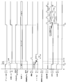
- FIG. 9 corresponds to the case where the in-vehicle battery 63 is completely discharged.
- the ON / OFF state of the ignition SW 60 the voltage value of the in-vehicle battery 63, the usage state of the internal power supply 66, the operation mode of the abnormality detection device 10, and the permission to determine the abnormal state of the vibration detection value by the acceleration sensor 30 State, presence / absence of vibration applied to the vehicle body, operation state of the warning means 40, presence / absence of abnormality detection determination, communication state by the in-vehicle phone 11, operation state of the GPS 20, and operation state of the GSM (in-vehicle phone).
- the ignition SW 60 is turned off at the time t10, that is, the time when the time ⁇ tB has elapsed when the engine is stopped and the power supply by the generator is stopped.
- the voltage value becomes substantially zero.
- the internal power supply 66 is switched from the use-prohibited state to the use state in order to continuously drive the abnormality detection device 10.
- the time ⁇ tB is set to 20 seconds because it takes some time for the generator to completely stop due to the inertial force of the crankshaft even after the ignition SW 60 is turned off. This is because of this. Further, the GPS 20 and GSM are deactivated at time t10. When the communication contract with the provider 4 is not concluded, GSM and the communication state are not turned on.
- the operation mode shifts from the normal mode M8 with the provider contract to the sleep mode M11, and the use of the vibration detection value for the abnormal state determination is permitted. Will be.
- the operation mode shifts to the sleep mode M10, and at the same time, in order to notify the user that the abnormality detection device 10 is functioning normally, as an alarm set, for example, 0.1 It is configured to make a confirmation sound in seconds. Thereafter, when a vibration is applied to the vehicle body, a warning sound is generated only for a predetermined time. In the present embodiment, a warning sound is sounded only during time AL1 with respect to the vibration applied at time t13. At this time, the abnormality detection device 10 does not determine that the abnormality is present. This is set to alert a warning sound, although it does not detect an abnormal state with a single vibration input, such as when a passerby contacts a stopped vehicle. Because.
- the ignition SW 60 is turned on and the engine is started by a kick starter or the like.
- the internal power supply 66 is switched to a use-prohibited state.
- the operation mode of the abnormality detection device 10 is switched from the sleep mode M10 to the normal mode M8 with a provider contract.
- GPS and GSM are activated, and then the in-vehicle telephone 11 performs communication with the provider 4 once every five minutes in order to update the latest information such as traffic jam information and weather forecasts, for example. Run with.
- GPS information that enables a history of the vehicle position with the passage of time to be kept during this communication is also transmitted to the provider 4.
- the operation mode is switched from the normal mode M8 with provider contract to the sleep mode M11. Also, the alarm set process accompanying the transition of the operation mode is executed in the same manner as in the example of FIG.
- the operation mode shifts to the sleep mode M, and the next It just waits for the ignition SW 60 to be turned on.
- the voltage value may gradually decrease due to natural discharge.
- the internal power supply 66 is switched to the use state, and it is determined whether or not the battery voltage has reached a predetermined voltage or less within 20 seconds from turning off the ignition SW (corresponding to step S102 in FIG. 8). .
- the predetermined value of the decrease rate is set to a decrease rate when decreasing from 12 V to 0 V in 1 second. Therefore, in the example of this figure, since the decrease rate is much smaller than the predetermined value, it is determined that the voltage is decreased due to natural discharge, and the alarm theft mode M11 is not entered.
- GPS and GSM that are stopped when the ignition SW is turned off are switched to the operating state when the ignition SW 60 is turned on at time t26, and wireless communication by the in-vehicle telephone 11 is performed from time t27.
- the abnormality detection device when the battery voltage becomes equal to or lower than the predetermined voltage within a predetermined time after the ignition SW is turned off, it is not determined as an abnormal state.
- the battery voltage becomes equal to or lower than the predetermined voltage after the predetermined time has elapsed and the battery voltage decrease rate is equal to or higher than the predetermined value it is determined to be in an abnormal state.
- the warning means In a vehicle in which the engine can be started by a kick starter, pushing, or the like even when it is awakened, it is possible to prevent the warning means from operating by determining that the engine is in an abnormal state as soon as the ignition switch is turned off and the engine is stopped.
- the vehicle-mounted battery is removed while the vehicle has stopped sufficiently after the ignition SW is turned off, it can be accurately determined as an abnormal state.
- the configuration and arrangement of the abnormality detection device, the types of various sensors and warning means for detecting abnormal conditions, the configuration of the display means, the function of the communication control unit, the type of communication standard of the in-vehicle telephone, the GPS usage method, the display means The lighting pattern, the predetermined time used for battery voltage monitoring control and the like are not limited to the above-described embodiment, and various changes can be made. For example, a method of learning from a battery voltage change history can be applied to the predetermined value of the battery voltage decrease rate in addition to a method of setting in advance in the program of the abnormality detection device.
- the abnormality detection device according to the present invention is not limited to a motorcycle, and can be applied to a tricycle, a four-wheel vehicle, or the like.
- the abnormality detection apparatus 10 for example, if it is determined that the vibration exceeding a predetermined magnitude is input once and it is determined to be in an abnormal state, the passerby mistakenly detects the vehicle body. There is a possibility that the warning means 40 may be activated because it is determined as an abnormal state even if the user has touched or if the user moves the bicycle slightly at the bicycle parking lot.
- the abnormality detection device 10 according to the present embodiment is in an abnormal state only when a predetermined pattern consisting of a combination of the vibration detection interval and the number of detections is met. It is comprised so that it may determine.
- a predetermined pattern for determining that the abnormal state determination unit 15 is in the abnormal state will be described with reference to the time chart of FIG.
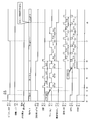
- FIG. 11 is a time chart showing the relationship between vibration input to the vehicle body and abnormal state determination.
- the abnormal state determination means 15 uses the output value of the timer 27 as a measurement means for measuring the vibration detection interval and the number of times of detection in addition to the detection value of the acceleration sensor 30 as a vibration sensor. It is characterized in that it prevents false detection of abnormal conditions.
- the ON / OFF state of the ignition SW 60 the voltage value of the in-vehicle battery 63, the usage state of the internal power supply 66, the operation mode of the abnormality detection device 10, and the permission to determine the abnormal state of the vibration detection value by the acceleration sensor 30 State, presence / absence of vibration applied to the vehicle body, operation state of alarm (horn 41) included in warning means 40, presence / absence of abnormality detection, communication state by in-vehicle phone 11, operation state of GPS 20, operation of GSM (in-vehicle phone) Indicates the state.
- the operation mode shifts from the normal mode M8 with provider contract to the sleep mode M10 at time t2 after the time ⁇ tA (60 seconds in this embodiment) has elapsed, and vibration detection is performed. Use of the value to determine the abnormal state is permitted.
- the GPS 20 and GSM are deactivated at time t1 when the ignition SW 60 is turned off. Further, when the communication contract with the provider 4 is not concluded, the GSM and the communication state are not turned on.
- the operation mode shifts to the sleep mode M10, and at the same time, the alarm set is notified to the user that the abnormality detection device 10 is functioning normally. It is configured to make a confirmation sound with a length of. Thereafter, when a vibration of a magnitude exceeding a predetermined value is applied to the vehicle body once, a warning sound is generated only for a very short time (for example, 5 seconds).
- a warning sound is sounded only for the time AL1 (for example, 5 seconds) against the vibration applied at time t3.
- the abnormality detection device 10 does not determine that the abnormality is present. This is to call attention to the parked vehicle by issuing a short warning sound, although it is not judged abnormal when a single vibration is input, such as when a passerby contacts This is because it is set as follows.
- the second vibration input is performed at time t4 when time ⁇ tB has elapsed from time t3 when the first vibration input was performed.
- the abnormality detection device 10 sounds a warning sound only during the time AL1 at this time t4.
- the third vibration input is performed at time t5 when time ⁇ tC has elapsed from time t4 when the second vibration input was made.
- a warning sound for calling attention is sounded only during the time AL1.
- the abnormal state determination means 15 indicates that the vehicle is in an abnormal state. And the operation mode of the abnormality detection device 10 is shifted from the sleep mode M10 to the alarm theft mode M11.
- the anomaly detection device 10 is configured to store a plurality of predetermined vibration input patterns and to store a vibration input history (detection interval and number of detections) for a predetermined time.
- a vibration input history detection interval and number of detections
- FIG. 11 “after a vibration having a magnitude greater than or equal to a predetermined value is first detected, a vibration having a magnitude greater than or equal to a predetermined value is detected once within 5 minutes. ”Is set to be determined to be in an abnormal state, and the times ⁇ tB, ⁇ tC, and ⁇ tD were within 5 minutes, respectively, and therefore, an abnormal state was determined at time t6.
- the predetermined vibration input pattern is: “After a vibration having a magnitude greater than or equal to a predetermined value is first detected, a vibration having a magnitude greater than or equal to a predetermined value is detected once within 5 to 10 minutes. It is possible to set the case where “repetition is repeated twice” or “when vibration having a magnitude equal to or greater than a predetermined value is continuously detected for 10 minutes or more”, or to use both in combination.
- the operation mode is switched to the alarm theft mode M11 at time t6, a warning by the alarm (horn 41) is started.
- the blinker lamp 42 is also blinked together with the alarm.
- the alarm is set to stop for 5 minutes after being activated for a time AL2 (for example, 3 minutes), so that a warning to a third party is effectively performed and the power consumption of the in-vehicle battery 63 is increased. It is possible to achieve both reductions.
- the operation patterns of the horn 41 and the blinker lamp 42 can be arbitrarily changed.
- the vibration detection permission state is switched from permission to prohibition, and the vehicle-mounted telephone 11 (see FIG. 1) is driven by the communication control unit 12, so that the vehicle body is in an abnormal state. Is notified to the user's telephone 3 or personal computer.
- vehicle current position information detected by GPS is also transmitted.
- this communication is performed once every five minutes, and the latest information can be updated as appropriate while reducing power consumption.
- the user of the vehicle can know the moving route of the vehicle after the vehicle reaches an abnormal state. It is also possible to take measures such as sending information related to the abnormal state of the vehicle to the provider 4 and requesting cooperation from the police or a security company via the provider 4.
- GPS and GSM are switched to the operating state at time t5 when the third vibration input is performed. This is because, at time t5, GPS and GSM are activated in advance in a state where it is determined to be abnormal if there is another vibration input within 5 minutes. This is a setting for recording the position of the vehicle. It is also effective for quickly starting wireless communication when an abnormal state is determined. Note that the movement history information by GPS is also recorded in a memory in the GPS.
- providing a plurality of vibration input patterns ensures that various abnormal states are determined as abnormal states, and how abnormalities are generated by the vibration patterns that have been determined as abnormal states. This is because there is a possibility that the user or the like can guess whether or not it has been.
- the vibration of the magnitude greater than or equal to the predetermined value is detected three times within the first 5 minutes after the vibration of the magnitude greater than or equal to the predetermined value is first detected.
- it can be detected that the exterior parts and the battery are removed.
- it may be possible to detect that a destructive operation such as a chain lock that connects the vehicle and the pillar or the like, or a bar lock that makes the wheels unrotatable is being performed.
- a vibration with a magnitude greater than a predetermined value is detected continuously for 10 minutes or more”, it is detected that the vehicle is immediately loaded on a truck for transportation and the truck is running. There is a possibility.
- the ignition SW 60 is switched on at time t7. This corresponds to, for example, a situation where the ignition SW 60 is turned on to stop the warning means 40 when the user has mistakenly shifted to the alarm theft mode M11 while maintaining the vehicle. To do.
- the abnormality detection device 10 according to the present embodiment is configured such that the alarm theft mode M11 is not canceled only by turning on the ignition SW 60.
- the transition from the alarm theft mode M11 to the normal mode M8 with provider contract is performed only when the user calls the in-vehicle telephone and transmits the theft mode release signal.
- the theft mode release signal is received at time t8, the alarm theft mode M11 shifts to the provider contracted normal mode M8, and the warning by the horn 41 and the blinker lamp 42 is also stopped. If the ignition SW 60 is off when the theft mode release signal is received, the process shifts to the sleep mode M10.
- a vibration having a magnitude greater than or equal to a predetermined value is detected within 5 minutes. Since it is determined that the state is abnormal only when a predetermined pattern consisting of a combination of the vibration detection interval and the number of times of detection is detected, such as when “detected once is repeated three times”. For example, when a passerby accidentally touches the vehicle body, it can be prevented that the abnormal state is determined only by detecting a temporary vibration.
- the configuration and arrangement of the abnormality detection device is not limited to a motorcycle, and can be applied to a tricycle, a four-wheel vehicle, or the like.
- Ignition SW 61 ... Stop lamp SW, 63 ... In-vehicle battery, 66 ... Internal power supply , 90: Check coupler, M1: Transportation mode, M2: Inspection mode, M3: Wake-up mode, M4: Normal Mode, M5 ... provider contract without the normal mode, M8 ... provider contract has normal mode, M9 ... Theft mode, M9 ... alarm theft mode, M10 ... sleep mode, M11 ... the alarm theft mode, M12 ... refueling mode
Landscapes
- Engineering & Computer Science (AREA)
- Mechanical Engineering (AREA)
- Radar, Positioning & Navigation (AREA)
- Remote Sensing (AREA)
- Alarm Systems (AREA)
- Burglar Alarm Systems (AREA)
- Emergency Alarm Devices (AREA)
Abstract
Description
1.トランスポーテーションモード(工場から販売店への運搬時を想定。内部電源を使用禁止とし、車載バッテリが接続されるまでの間の電力消費を抑える)
2.インスペクションモード(異常検知装置の検査時を想定)
3.ウェイクアップモード(ノーマルモードへの切り換え操作を受け付ける)
4.ノーマルモード(走行中等の通常使用時を想定。車体に加えられた振動等を検知しても警告手段を作動させない)
5.給油モード(ユーザによる給油時(イグニッションSWオフ)を想定。車体に加えられた振動等を検知しても警告手段を作動させない)
6.スリープモード(イグニッションSWオフの通常降車時を想定。車体に加えられた振動等の検知に伴って警告手段を作動させる)
7.セフトモード(イグニッションキーが付いたまま車両が移動等された状態を想定。車両が異常状態であることをユーザが電話機を用いて異常検知装置に認識させて、警告手段を作動させる)
8.アラームセフトモード(イグニッションキーを抜いた状態で異常が発生した状態を想定。警告手段を作動させると共に、ユーザの電話機等に通知する)
Claims (9)
- 電圧センサによって検知される車載バッテリ(63)のバッテリ電圧に基づいて車両の異常状態を検知すると共に、車両追跡機能を有する異常検知および車両追跡装置(10)において、
前記異常検知および車両追跡装置(10)を作動させる内部電源(66)と、
前記バッテリ電圧を検知するバッテリ電圧検知手段(32)と、
前記車両(1)が異常状態であると判定すると、前記異常検知および車両追跡装置(10)の動作モードを、少なくとも警告手段(40)を作動させるアラームセフトモード(M11)に切り換える動作モード切換手段(17)を具備し、
前記動作モード切換手段(17)は、車両(1)の主電源のオンオフを切り換えるイグニッションスイッチ(60)がオフされた際の前記バッテリ電圧に降下度合に応じて前記動作モードをアラームセフトモード(M11)に切り換えることを特徴とする異常検知および車両追跡装置。 - 前記動作モード切換手段(17)は、車両(1)の主電源のオンオフを切り換えるイグニッションスイッチ(60)がオフにされてから所定時間以内に前記バッテリ電圧が所定電圧以下となった場合には、前記車両(1)が異常状態であるとは判定せず、一方、前記所定時間が経過した後に前記バッテリ電圧が所定電圧以下となり、かつ前記バッテリ電圧の減少率が所定値以上である場合には、前記車両(1)が異常状態であると判定して、前記動作モードをアラームセフトモード(M11)に切り換えることを特徴とする請求項1に記載の異常検知および車両追跡装置。
- 前記動作モード切換手段(17)は、前記所定時間が経過した後に前記バッテリ電圧が所定電圧以下となり、かつ前記バッテリ電圧の減少率が所定値未満である場合には、前記車両(1)が異常状態ではないと判定して、前記動作モードの切り換えを実行しないことを特徴とする請求項2に記載の異常検知および車両追跡装置。
- 前記異常検知および車両追跡装置(10)は、前記車載バッテリ(63)のバッテリ電圧が所定値以下となった際に、前記異常検知および車両追跡装置(10)を継続駆動させる内部電源(66)を具備することを特徴とする請求項2または3に記載の異常検知および車両追跡装置。
- 車両(1)に加えられた振動を検知する振動センサ(30)を含む異常検知手段によって車両(1)の異常状態を検知すると共に、車両追跡機能を有し、
前記振動の検知間隔および検知回数を計測する計測手段(27)と、
前記振動センサ(30)の出力信号に基づいて、車両(1)の異常状態を判定する異常状態判定手段(15)とを具備し、
前記異常状態判定手段(15)は、前記振動の検知間隔と検知回数との組み合わせからなる予め定められた複数のパターンを記憶し、当該パターンにて車両(1)の異常状態を判定することを特徴とする請求項1に記載の異常検知および車両追跡装置。 - 公共電話回線を介した無線通信が可能な車載電話機(11)と、
前記異常状態判定手段(15)によって異常状態であると判定された際に、前記車載電話機(11)を用いて、異常状態にあることを外部に通知可能な通信制御部(12)とを具備することを特徴とする請求項5に記載の異常検知および車両追跡装置。 - 前記所定のパターンは、最初に所定値以上の大きさの振動が検知された後、5分以内の間に所定値以上の大きさの振動が1回検知されることが、3度繰り返されることであることを特徴とする請求項5または6に記載の異常検知および車両追跡装置。
- 前記所定のパターンは、最初に所定値以上の大きさの振動が検知された後、5分以上10分以内の間に所定値以上の大きさの振動が1回検知されることが、2度繰り返されることであることを特徴とする請求項5または6に記載の異常検知および車両追跡装置。
- 前記所定のパターンは、所定値以上の大きさの振動が10分以上継続して検知されることであることを特徴とする請求項5または6に記載の異常検知および車両追跡装置。
Priority Applications (3)
| Application Number | Priority Date | Filing Date | Title |
|---|---|---|---|
| CN2010800107348A CN102341281B (zh) | 2009-03-06 | 2010-02-12 | 异常检测和车辆追踪装置 |
| BRPI1016248A BRPI1016248B1 (pt) | 2009-03-06 | 2010-02-12 | aparelho de detecção de anormalidade e rastreamento de veículo |
| EP10748609.4A EP2404792B1 (en) | 2009-03-06 | 2010-02-12 | Abnormality detection and vehicle tracking device |
Applications Claiming Priority (4)
| Application Number | Priority Date | Filing Date | Title |
|---|---|---|---|
| JP2009-054209 | 2009-03-06 | ||
| JP2009054208A JP5419494B2 (ja) | 2009-03-06 | 2009-03-06 | 異常検知および車両追跡装置 |
| JP2009-054208 | 2009-03-06 | ||
| JP2009054209A JP5419495B2 (ja) | 2009-03-06 | 2009-03-06 | 異常検知および車両追跡装置 |
Publications (1)
| Publication Number | Publication Date |
|---|---|
| WO2010101013A1 true WO2010101013A1 (ja) | 2010-09-10 |
Family
ID=42709574
Family Applications (1)
| Application Number | Title | Priority Date | Filing Date |
|---|---|---|---|
| PCT/JP2010/052063 Ceased WO2010101013A1 (ja) | 2009-03-06 | 2010-02-12 | 異常検知および車両追跡装置 |
Country Status (4)
| Country | Link |
|---|---|
| EP (1) | EP2404792B1 (ja) |
| CN (1) | CN102341281B (ja) |
| BR (1) | BRPI1016248B1 (ja) |
| WO (1) | WO2010101013A1 (ja) |
Cited By (6)
| Publication number | Priority date | Publication date | Assignee | Title |
|---|---|---|---|---|
| WO2012131667A1 (en) | 2011-03-28 | 2012-10-04 | Sosmart Rescue Ltd. | A multidimensional system for monitoring and tracking states and conditions |
| CN108407937A (zh) * | 2018-04-13 | 2018-08-17 | 深圳市海鸥音科技有限公司 | 电动车震动报警装置 |
| US10126922B2 (en) | 2014-09-10 | 2018-11-13 | Mitsubishi Heavy Industries Machinery Systems, Ltd. | On-board unit and fault determination method |
| CN111929600A (zh) * | 2020-08-10 | 2020-11-13 | 吉利汽车研究院(宁波)有限公司 | 蓄电池诊断监测方法、监测系统、车辆及车联网云平台 |
| CN113511154A (zh) * | 2020-04-10 | 2021-10-19 | 广州汽车集团股份有限公司 | 一种车辆强制休眠控制方法、装置及车辆 |
| CN114162078A (zh) * | 2021-11-25 | 2022-03-11 | 上汽通用五菱汽车股份有限公司 | 一种汽车远程报警防盗控制方法及系统 |
Families Citing this family (14)
| Publication number | Priority date | Publication date | Assignee | Title |
|---|---|---|---|---|
| CN103863442A (zh) * | 2012-12-17 | 2014-06-18 | 上海锘钛通信科技有限公司 | 基于gps技术的防盗型摩托车点火器 |
| KR101673780B1 (ko) * | 2015-06-16 | 2016-11-08 | 현대자동차주식회사 | 고장진단 제어방법 |
| KR101759139B1 (ko) * | 2016-01-07 | 2017-07-18 | 현대자동차주식회사 | 지오펜스 비콘을 이용한 차량 헤드 유닛 프리 부팅 제어 방법 및 그를 위한 장치 및 시스템 |
| JP2017201521A (ja) * | 2016-04-28 | 2017-11-09 | オムロン株式会社 | 出力制御ユニット、出力制御システム、出力制御ユニットの制御方法 |
| JP6197089B1 (ja) * | 2016-10-25 | 2017-09-13 | ナブテスコ株式会社 | 船舶において消費された燃料油の量を示すデータの信頼性を確認するための装置およびプログラム |
| CN106427894A (zh) * | 2016-11-10 | 2017-02-22 | 成都路行通信息技术有限公司 | 追踪被盗车辆的方法 |
| CN107132489B (zh) * | 2017-06-30 | 2021-01-05 | 浙江绿源电动车有限公司 | 电池容量检测方法、车辆状态判断方法、电池组及电动车 |
| GB201820073D0 (en) | 2018-12-10 | 2019-01-23 | Tomtom Telematics Bv | Vehicle battery monitoring |
| WO2020157942A1 (ja) * | 2019-01-31 | 2020-08-06 | 本田技研工業株式会社 | 車両遠隔制御システム、車両遠隔制御方法、サーバ、端末装置及び通信装置 |
| JP7120948B2 (ja) * | 2019-03-08 | 2022-08-17 | シャープ株式会社 | 通信端末 |
| DE102020113870A1 (de) * | 2019-05-24 | 2020-11-26 | ThingsOfficer GmbH | Vorrichtung und Verfahren zur Überwachung eines Fahrzeugs |
| EP3923251B1 (en) | 2020-06-10 | 2025-01-01 | Bridgestone Mobility Solutions B.V. | Monitoring voltage measurements for a vehicle battery |
| US11597348B2 (en) * | 2020-07-01 | 2023-03-07 | Ford Global Technologies, Llc | Detecting abnormal CAN bus wake-up pattern |
| CN118865522B (zh) * | 2024-09-29 | 2025-01-28 | 江苏奥易克斯汽车电子科技股份有限公司 | 一种汽车电控单元多源数据融合的状态感知系统 |
Citations (5)
| Publication number | Priority date | Publication date | Assignee | Title |
|---|---|---|---|---|
| JPH10169269A (ja) | 1996-12-13 | 1998-06-23 | Honda Lock Mfg Co Ltd | 車両用盗難防止装置 |
| JPH10295044A (ja) * | 1997-04-18 | 1998-11-04 | Yazaki Corp | 電池残存容量測定装置 |
| JPH11334666A (ja) * | 1998-05-27 | 1999-12-07 | Iic:Kk | 車両用盗難防止装置 |
| JP3163242B2 (ja) | 1996-01-18 | 2001-05-08 | 富士通株式会社 | 盗難防止装置及び盗難防止方法 |
| JP2007170953A (ja) * | 2005-12-21 | 2007-07-05 | Toyota Motor Corp | 二次電池の劣化判定装置 |
Family Cites Families (5)
| Publication number | Priority date | Publication date | Assignee | Title |
|---|---|---|---|---|
| JP3493917B2 (ja) * | 1995-12-12 | 2004-02-03 | 株式会社デンソー | 警報装置 |
| JP4189154B2 (ja) * | 2001-04-02 | 2008-12-03 | 本田技研工業株式会社 | 自動二輪車の盗難対策装置設置構造 |
| CN2719666Y (zh) * | 2004-04-26 | 2005-08-24 | 黄明 | Gsm远程遥控汽车防盗系统 |
| KR100639372B1 (ko) * | 2004-11-08 | 2006-10-26 | 엘지전자 주식회사 | 이동통신망을 이용한 차량도난방지장치 및 그 제어방법 |
| IL172003A0 (en) * | 2005-11-16 | 2006-04-10 | Starcom Gps Systems Ltd | Interface for a communication and positioning device |
-
2010
- 2010-02-12 WO PCT/JP2010/052063 patent/WO2010101013A1/ja not_active Ceased
- 2010-02-12 CN CN2010800107348A patent/CN102341281B/zh not_active Expired - Fee Related
- 2010-02-12 BR BRPI1016248A patent/BRPI1016248B1/pt not_active IP Right Cessation
- 2010-02-12 EP EP10748609.4A patent/EP2404792B1/en not_active Not-in-force
Patent Citations (5)
| Publication number | Priority date | Publication date | Assignee | Title |
|---|---|---|---|---|
| JP3163242B2 (ja) | 1996-01-18 | 2001-05-08 | 富士通株式会社 | 盗難防止装置及び盗難防止方法 |
| JPH10169269A (ja) | 1996-12-13 | 1998-06-23 | Honda Lock Mfg Co Ltd | 車両用盗難防止装置 |
| JPH10295044A (ja) * | 1997-04-18 | 1998-11-04 | Yazaki Corp | 電池残存容量測定装置 |
| JPH11334666A (ja) * | 1998-05-27 | 1999-12-07 | Iic:Kk | 車両用盗難防止装置 |
| JP2007170953A (ja) * | 2005-12-21 | 2007-07-05 | Toyota Motor Corp | 二次電池の劣化判定装置 |
Non-Patent Citations (1)
| Title |
|---|
| See also references of EP2404792A4 |
Cited By (11)
| Publication number | Priority date | Publication date | Assignee | Title |
|---|---|---|---|---|
| WO2012131667A1 (en) | 2011-03-28 | 2012-10-04 | Sosmart Rescue Ltd. | A multidimensional system for monitoring and tracking states and conditions |
| EP2691738A4 (en) * | 2011-03-28 | 2014-12-31 | Sosmart Rescue Ltd | MULTIDIMENSIONAL SYSTEM FOR MONITORING AND MONITORING STATES AND CONDITIONS |
| US10126922B2 (en) | 2014-09-10 | 2018-11-13 | Mitsubishi Heavy Industries Machinery Systems, Ltd. | On-board unit and fault determination method |
| CN108407937A (zh) * | 2018-04-13 | 2018-08-17 | 深圳市海鸥音科技有限公司 | 电动车震动报警装置 |
| CN108407937B (zh) * | 2018-04-13 | 2020-11-27 | 深圳市海鸥音科技有限公司 | 电动车震动报警装置 |
| CN113511154A (zh) * | 2020-04-10 | 2021-10-19 | 广州汽车集团股份有限公司 | 一种车辆强制休眠控制方法、装置及车辆 |
| CN113511154B (zh) * | 2020-04-10 | 2023-10-03 | 广州汽车集团股份有限公司 | 一种车辆强制休眠控制方法、装置及车辆 |
| CN111929600A (zh) * | 2020-08-10 | 2020-11-13 | 吉利汽车研究院(宁波)有限公司 | 蓄电池诊断监测方法、监测系统、车辆及车联网云平台 |
| CN111929600B (zh) * | 2020-08-10 | 2023-09-08 | 吉利汽车研究院(宁波)有限公司 | 蓄电池诊断监测方法、监测系统、车辆及车联网云平台 |
| CN114162078A (zh) * | 2021-11-25 | 2022-03-11 | 上汽通用五菱汽车股份有限公司 | 一种汽车远程报警防盗控制方法及系统 |
| CN114162078B (zh) * | 2021-11-25 | 2024-03-15 | 上汽通用五菱汽车股份有限公司 | 一种汽车远程报警防盗控制方法及系统 |
Also Published As
| Publication number | Publication date |
|---|---|
| EP2404792B1 (en) | 2013-12-25 |
| BRPI1016248A2 (pt) | 2016-04-26 |
| EP2404792A1 (en) | 2012-01-11 |
| CN102341281A (zh) | 2012-02-01 |
| BRPI1016248B1 (pt) | 2019-12-17 |
| EP2404792A4 (en) | 2012-08-22 |
| CN102341281B (zh) | 2013-10-09 |
Similar Documents
| Publication | Publication Date | Title |
|---|---|---|
| WO2010101013A1 (ja) | 異常検知および車両追跡装置 | |
| JP5419496B2 (ja) | 異常検知および車両追跡装置 | |
| JP5419494B2 (ja) | 異常検知および車両追跡装置 | |
| US11878652B2 (en) | Vehicle remote control system | |
| US8031048B2 (en) | Vehicle antitheft system and vehicle antitheft method | |
| US20050242929A1 (en) | Theft prevention apparatus of leisure vehicle | |
| US20010037168A1 (en) | Vehicle information communication system and method capable of communicating with external management station | |
| JP5255379B2 (ja) | 盗難防止装置 | |
| JP4329945B2 (ja) | エンジン始動システム | |
| US7964986B2 (en) | Drive control apparatus, system and method | |
| JP5419495B2 (ja) | 異常検知および車両追跡装置 | |
| CN100434674C (zh) | 车辆发动机控制系统和方法 | |
| JP5784782B1 (ja) | 盗難防止機能付き内燃機関制御装置 | |
| JP5968488B1 (ja) | 車両用制御装置 | |
| JP2007076416A (ja) | 車両状態監視装置 | |
| JP2001254546A (ja) | 電池消耗状態判別装置 | |
| JP6009606B1 (ja) | 車両用制御装置 | |
| JP2006273239A (ja) | 車両制御装置及び車両の停止方法 | |
| JP2007223555A (ja) | 車両用セキュリティ制御装置 |
Legal Events
| Date | Code | Title | Description |
|---|---|---|---|
| WWE | Wipo information: entry into national phase |
Ref document number: 201080010734.8 Country of ref document: CN |
|
| 121 | Ep: the epo has been informed by wipo that ep was designated in this application |
Ref document number: 10748609 Country of ref document: EP Kind code of ref document: A1 |
|
| NENP | Non-entry into the national phase |
Ref country code: DE |
|
| WWE | Wipo information: entry into national phase |
Ref document number: 2010748609 Country of ref document: EP |
|
| REG | Reference to national code |
Ref country code: BR Ref legal event code: B01A Ref document number: PI1016248 Country of ref document: BR |
|
| ENP | Entry into the national phase |
Ref document number: PI1016248 Country of ref document: BR Kind code of ref document: A2 Effective date: 20110906 |