WO2010103762A1 - カテーテルおよびカテーテルの製造方法 - Google Patents
カテーテルおよびカテーテルの製造方法 Download PDFInfo
- Publication number
- WO2010103762A1 WO2010103762A1 PCT/JP2010/001532 JP2010001532W WO2010103762A1 WO 2010103762 A1 WO2010103762 A1 WO 2010103762A1 JP 2010001532 W JP2010001532 W JP 2010001532W WO 2010103762 A1 WO2010103762 A1 WO 2010103762A1
- Authority
- WO
- WIPO (PCT)
- Prior art keywords
- resin layer
- resin
- catheter
- layer
- distal end
- Prior art date
- Legal status (The legal status is an assumption and is not a legal conclusion. Google has not performed a legal analysis and makes no representation as to the accuracy of the status listed.)
- Ceased
Links
- 0 CC(CC*)CCCC1(C)CCCC1 Chemical compound CC(CC*)CCCC1(C)CCCC1 0.000 description 1
Images


Classifications
-
- A—HUMAN NECESSITIES
- A61—MEDICAL OR VETERINARY SCIENCE; HYGIENE
- A61M—DEVICES FOR INTRODUCING MEDIA INTO, OR ONTO, THE BODY; DEVICES FOR TRANSDUCING BODY MEDIA OR FOR TAKING MEDIA FROM THE BODY; DEVICES FOR PRODUCING OR ENDING SLEEP OR STUPOR
- A61M25/00—Catheters; Hollow probes
- A61M25/0043—Catheters; Hollow probes characterised by structural features
- A61M25/0045—Catheters; Hollow probes characterised by structural features multi-layered, e.g. coated
-
- A—HUMAN NECESSITIES
- A61—MEDICAL OR VETERINARY SCIENCE; HYGIENE
- A61M—DEVICES FOR INTRODUCING MEDIA INTO, OR ONTO, THE BODY; DEVICES FOR TRANSDUCING BODY MEDIA OR FOR TAKING MEDIA FROM THE BODY; DEVICES FOR PRODUCING OR ENDING SLEEP OR STUPOR
- A61M25/00—Catheters; Hollow probes
- A61M25/01—Introducing, guiding, advancing, emplacing or holding catheters
-
- A—HUMAN NECESSITIES
- A61—MEDICAL OR VETERINARY SCIENCE; HYGIENE
- A61B—DIAGNOSIS; SURGERY; IDENTIFICATION
- A61B1/00—Instruments for performing medical examinations of the interior of cavities or tubes of the body by visual or photographical inspection, e.g. endoscopes; Illuminating arrangements therefor
- A61B1/00064—Constructional details of the endoscope body
- A61B1/0011—Manufacturing of endoscope parts
-
- A—HUMAN NECESSITIES
- A61—MEDICAL OR VETERINARY SCIENCE; HYGIENE
- A61L—METHODS OR APPARATUS FOR STERILISING MATERIALS OR OBJECTS IN GENERAL; DISINFECTION, STERILISATION OR DEODORISATION OF AIR; CHEMICAL ASPECTS OF BANDAGES, DRESSINGS, ABSORBENT PADS OR SURGICAL ARTICLES; MATERIALS FOR BANDAGES, DRESSINGS, ABSORBENT PADS OR SURGICAL ARTICLES
- A61L29/00—Materials for catheters, medical tubing, cannulae, or endoscopes or for coating catheters
- A61L29/08—Materials for coatings
- A61L29/085—Macromolecular materials
-
- A—HUMAN NECESSITIES
- A61—MEDICAL OR VETERINARY SCIENCE; HYGIENE
- A61M—DEVICES FOR INTRODUCING MEDIA INTO, OR ONTO, THE BODY; DEVICES FOR TRANSDUCING BODY MEDIA OR FOR TAKING MEDIA FROM THE BODY; DEVICES FOR PRODUCING OR ENDING SLEEP OR STUPOR
- A61M25/00—Catheters; Hollow probes
-
- A—HUMAN NECESSITIES
- A61—MEDICAL OR VETERINARY SCIENCE; HYGIENE
- A61M—DEVICES FOR INTRODUCING MEDIA INTO, OR ONTO, THE BODY; DEVICES FOR TRANSDUCING BODY MEDIA OR FOR TAKING MEDIA FROM THE BODY; DEVICES FOR PRODUCING OR ENDING SLEEP OR STUPOR
- A61M25/00—Catheters; Hollow probes
- A61M25/0009—Making of catheters or other medical or surgical tubes
- A61M25/0012—Making of catheters or other medical or surgical tubes with embedded structures, e.g. coils, braids, meshes, strands or radiopaque coils
-
- A—HUMAN NECESSITIES
- A61—MEDICAL OR VETERINARY SCIENCE; HYGIENE
- A61M—DEVICES FOR INTRODUCING MEDIA INTO, OR ONTO, THE BODY; DEVICES FOR TRANSDUCING BODY MEDIA OR FOR TAKING MEDIA FROM THE BODY; DEVICES FOR PRODUCING OR ENDING SLEEP OR STUPOR
- A61M25/00—Catheters; Hollow probes
- A61M25/0043—Catheters; Hollow probes characterised by structural features
- A61M25/005—Catheters; Hollow probes characterised by structural features with embedded materials for reinforcement, e.g. wires, coils, braids
-
- A—HUMAN NECESSITIES
- A61—MEDICAL OR VETERINARY SCIENCE; HYGIENE
- A61M—DEVICES FOR INTRODUCING MEDIA INTO, OR ONTO, THE BODY; DEVICES FOR TRANSDUCING BODY MEDIA OR FOR TAKING MEDIA FROM THE BODY; DEVICES FOR PRODUCING OR ENDING SLEEP OR STUPOR
- A61M25/00—Catheters; Hollow probes
- A61M25/0043—Catheters; Hollow probes characterised by structural features
- A61M25/0054—Catheters; Hollow probes characterised by structural features with regions for increasing flexibility
-
- B—PERFORMING OPERATIONS; TRANSPORTING
- B29—WORKING OF PLASTICS; WORKING OF SUBSTANCES IN A PLASTIC STATE IN GENERAL
- B29C—SHAPING OR JOINING OF PLASTICS; SHAPING OF MATERIAL IN A PLASTIC STATE, NOT OTHERWISE PROVIDED FOR; AFTER-TREATMENT OF THE SHAPED PRODUCTS, e.g. REPAIRING
- B29C48/00—Extrusion moulding, i.e. expressing the moulding material through a die or nozzle which imparts the desired form; Apparatus therefor
- B29C48/03—Extrusion moulding, i.e. expressing the moulding material through a die or nozzle which imparts the desired form; Apparatus therefor characterised by the shape of the extruded material at extrusion
- B29C48/09—Articles with cross-sections having partially or fully enclosed cavities, e.g. pipes or channels
-
- B—PERFORMING OPERATIONS; TRANSPORTING
- B29—WORKING OF PLASTICS; WORKING OF SUBSTANCES IN A PLASTIC STATE IN GENERAL
- B29C—SHAPING OR JOINING OF PLASTICS; SHAPING OF MATERIAL IN A PLASTIC STATE, NOT OTHERWISE PROVIDED FOR; AFTER-TREATMENT OF THE SHAPED PRODUCTS, e.g. REPAIRING
- B29C48/00—Extrusion moulding, i.e. expressing the moulding material through a die or nozzle which imparts the desired form; Apparatus therefor
- B29C48/15—Extrusion moulding, i.e. expressing the moulding material through a die or nozzle which imparts the desired form; Apparatus therefor incorporating preformed parts or layers, e.g. extrusion moulding around inserts
- B29C48/154—Coating solid articles, i.e. non-hollow articles
-
- B—PERFORMING OPERATIONS; TRANSPORTING
- B29—WORKING OF PLASTICS; WORKING OF SUBSTANCES IN A PLASTIC STATE IN GENERAL
- B29C—SHAPING OR JOINING OF PLASTICS; SHAPING OF MATERIAL IN A PLASTIC STATE, NOT OTHERWISE PROVIDED FOR; AFTER-TREATMENT OF THE SHAPED PRODUCTS, e.g. REPAIRING
- B29C48/00—Extrusion moulding, i.e. expressing the moulding material through a die or nozzle which imparts the desired form; Apparatus therefor
- B29C48/16—Articles comprising two or more components, e.g. co-extruded layers
- B29C48/18—Articles comprising two or more components, e.g. co-extruded layers the components being layers
- B29C48/21—Articles comprising two or more components, e.g. co-extruded layers the components being layers the layers being joined at their surfaces
-
- B—PERFORMING OPERATIONS; TRANSPORTING
- B29—WORKING OF PLASTICS; WORKING OF SUBSTANCES IN A PLASTIC STATE IN GENERAL
- B29C—SHAPING OR JOINING OF PLASTICS; SHAPING OF MATERIAL IN A PLASTIC STATE, NOT OTHERWISE PROVIDED FOR; AFTER-TREATMENT OF THE SHAPED PRODUCTS, e.g. REPAIRING
- B29C48/00—Extrusion moulding, i.e. expressing the moulding material through a die or nozzle which imparts the desired form; Apparatus therefor
- B29C48/25—Component parts, details or accessories; Auxiliary operations
- B29C48/30—Extrusion nozzles or dies
- B29C48/32—Extrusion nozzles or dies with annular openings, e.g. for forming tubular articles
- B29C48/335—Multiple annular extrusion nozzles in coaxial arrangement, e.g. for making multi-layered tubular articles
- B29C48/336—Multiple annular extrusion nozzles in coaxial arrangement, e.g. for making multi-layered tubular articles the components merging one by one down streams in the die
- B29C48/3366—Multiple annular extrusion nozzles in coaxial arrangement, e.g. for making multi-layered tubular articles the components merging one by one down streams in the die using a die with concentric parts, e.g. rings, cylinders
-
- A—HUMAN NECESSITIES
- A61—MEDICAL OR VETERINARY SCIENCE; HYGIENE
- A61M—DEVICES FOR INTRODUCING MEDIA INTO, OR ONTO, THE BODY; DEVICES FOR TRANSDUCING BODY MEDIA OR FOR TAKING MEDIA FROM THE BODY; DEVICES FOR PRODUCING OR ENDING SLEEP OR STUPOR
- A61M25/00—Catheters; Hollow probes
- A61M25/01—Introducing, guiding, advancing, emplacing or holding catheters
- A61M25/0105—Steering means as part of the catheter or advancing means; Markers for positioning
- A61M25/0108—Steering means as part of the catheter or advancing means; Markers for positioning using radio-opaque or ultrasound markers
-
- B—PERFORMING OPERATIONS; TRANSPORTING
- B29—WORKING OF PLASTICS; WORKING OF SUBSTANCES IN A PLASTIC STATE IN GENERAL
- B29C—SHAPING OR JOINING OF PLASTICS; SHAPING OF MATERIAL IN A PLASTIC STATE, NOT OTHERWISE PROVIDED FOR; AFTER-TREATMENT OF THE SHAPED PRODUCTS, e.g. REPAIRING
- B29C48/00—Extrusion moulding, i.e. expressing the moulding material through a die or nozzle which imparts the desired form; Apparatus therefor
- B29C48/25—Component parts, details or accessories; Auxiliary operations
- B29C48/30—Extrusion nozzles or dies
- B29C48/32—Extrusion nozzles or dies with annular openings, e.g. for forming tubular articles
- B29C48/34—Cross-head annular extrusion nozzles, i.e. for simultaneously receiving moulding material and the preform to be coated
-
- B—PERFORMING OPERATIONS; TRANSPORTING
- B29—WORKING OF PLASTICS; WORKING OF SUBSTANCES IN A PLASTIC STATE IN GENERAL
- B29L—INDEXING SCHEME ASSOCIATED WITH SUBCLASS B29C, RELATING TO PARTICULAR ARTICLES
- B29L2031/00—Other particular articles
- B29L2031/753—Medical equipment; Accessories therefor
- B29L2031/7542—Catheters
Definitions
- the present invention relates to a catheter and a method for manufacturing the catheter.
- a catheter capable of manipulating the direction of entry into a body cavity by bending a distal end portion.
- a wire fixed to the distal end is operated on the proximal end side (see Patent Document 1 below).
- a wire (operation line) penetrating the lumen of the catheter body (tubular body) has a predetermined rigidity, and the distal end of the tubular body is bent by pushing the wire.
- the tubular main body is divided into four or five regions having different flexibility and is partitioned in stages in the longitudinal direction, and the rigidity is higher at the proximal end side, and conversely at the distal end side. It is configured flexibly. Thereby, it is supposed that the distal end portion can be largely bent when the wire is pushed in while maintaining the stiffness of the catheter at a predetermined level.
- the diameter of catheters has been reduced from the viewpoint of penetration into blood vessels, and those having an outer diameter of 1 mm or less have been provided.
- the inner diameter of the sub-lumen through which the operation line is inserted is suppressed to an extremely small diameter of 10 to several tens ⁇ m or less. It is hoped that.
- a delicate bending operation by an operation line is performed. It becomes difficult.
- the bending rigidity (second moment of section) of the tubular body is generally proportional to the fourth power of the diameter, but the flexibility of the tubular body becomes discontinuous at the boundary where the flexibility changes stepwise. This complicates the relationship between the length of pushing or pulling out the operation line and the amount of bending of the distal end, making it difficult to displace the distal end by a desired amount of bending.
- the conventional catheter it is used when the flexibility of the tubular body is gradually changed by dividing into a large number of regions in the longitudinal direction so that the flexibility of the tubular body changes substantially continuously. There is a problem in molding cost and material cost because the number of types of materials is extremely large.
- the present invention has been made in view of the above problems, and provides a catheter that can be delicately bent by an operation line and is excellent in manufacturability, and a method for manufacturing the same, regardless of the diameter of the sublumen. is there.
- the catheter of the present invention includes a tubular body in which a main lumen and a sub-lumen having a diameter smaller than that of the main lumen are formed in the longitudinal direction, and a slidably inserted through the sub-lumen.
- An operation line having a distal end fixed to the distal end, and the tubular body includes a first resin layer made of a resin material and a second resin layer having a higher hardness than the first resin layer in the thickness direction. And the thickness of the second resin layer increases from the distal end side toward the proximal end side.
- the thickness of the first resin layer may monotonously decrease from the distal end side to the proximal end side of the tubular body.
- the first resin layer and the second resin layer have a hardness intermediate between the first resin layer and the second resin layer.
- a third resin layer may be laminated.
- the second resin layer may be provided on the outer peripheral side with respect to the first resin layer.
- the resin material constituting the second resin layer may have lower adhesiveness than the resin material constituting the first resin layer.
- the catheter of the present invention further includes, as a more specific embodiment, a tubular inner layer in which the main lumen is formed, and a blade layer formed by knitting wires around the inner layer.
- the first resin layer may be provided in close contact with the blade layer.
- the sub-lumen through which the operation line is inserted may be formed with a through hole on the outer peripheral side of the first resin layer.
- the first resin layer is provided on the outer peripheral side of the second resin layer with respect to a partial length on the distal end side of the tubular body. It may be.
- the catheter manufacturing method of the present invention includes a main body and a tubular body in which a sub-lumen having a smaller diameter than the main lumen is formed in a longitudinal direction, an operation line slidably inserted in the sub-lumen, A first resin material in a molten state, and a second resin material in a molten state having a hardness higher than that of the first resin material at room temperature and introducing the operation line; , While increasing the discharge amount of the second resin material relative to the discharge amount of the first resin material, the first and second resin materials are extruded from the die together to form the tubular body. Process.
- the molten third resin material into which the operation line is introduced is combined with the molten second resin material from the die.
- the main body molding step is performed after the pre-extrusion step of extruding together, and in the main body molding step, the first and third resin materials are increased while increasing the discharge amount of the second resin material with respect to the discharge amount of the first and third resin materials.
- the tubular body may be formed by extruding the second and third resin materials together from the die.
- the various components of the present invention do not have to be individually independent, that a plurality of components are formed as one member, and one component is formed of a plurality of members. It may be that a certain component is a part of another component, a part of a certain component overlaps a part of another component, and the like.
- the stiffness of the catheter and the distal end portion A delicate bending operation using the operation line can be stably realized while achieving both good flexibility.
- FIG. 3 is a sectional view taken along the line III-III in FIG. 2. It is a side view explaining operation
- movement of a catheter (a) is a longitudinal cross-sectional schematic diagram which shows the catheter of a natural state, (b) is a longitudinal cross-sectional schematic diagram which shows the catheter of the state which pulled the operation line. It is a schematic block diagram of the manufacturing apparatus of a sheath. It is a longitudinal cross-sectional schematic diagram of an extruder. It is a partial longitudinal cross-sectional schematic diagram which shows the catheter which concerns on the 2nd modification of this embodiment.
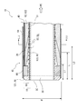
- FIG. 1 is a partial vertical cross-sectional schematic diagram showing a catheter 10 of the present embodiment.
- the figure shows a cross section of the distal end of the catheter 10 cut in the longitudinal direction.
- the left side of the figure corresponds to the distal end (tip) side of the catheter 10, and the right side corresponds to the proximal end (base end) side.
- the proximal end side of the catheter 10 is not shown.
- FIG. 2 is a partial longitudinal sectional view showing the catheter 10 according to the first modification of the present embodiment.
- 3 is a cross-sectional view (cross-sectional view) taken along the line III-III in FIG.
- the catheter 10 of the present embodiment has a tubular main body (sheath 16) and an operation line 40.
- a main lumen 20 and a sub-lumen 30 having a smaller diameter than the main lumen 20 are formed with through holes in the longitudinal direction.
- the operation line 40 is slidably inserted into the sub-lumen 30, and the tip is fixed to the distal end portion 15 of the sheath 16.
- the sheath 16 of the present embodiment includes a first resin layer 61 made of a resin material and a second resin layer 62 having a hardness higher than that of the first resin layer 61 in the thickness direction. Become. In the sheath 16, the thickness of the second resin layer 62 increases from the distal end side toward the proximal end side.
- the sheath 16 may further include other resin layers in the thickness direction or the axial direction in addition to the first resin layer 61 and the second resin layer 62.
- the catheter 10 of the first modification shown in FIG. 2 includes a third resin layer 63 that is further laminated in the thickness direction.
- a plurality of sublumens 30 are arranged in a distributed manner in the circumferential direction of the main lumen 20. Specifically, three sub-lumens 30 are arranged around the main lumen 20 at intervals of 120 degrees, and one operation line 40 is slidably inserted into each.
- the distal end portion 15 of the catheter 10 refers to a predetermined length region including the distal end DE of the catheter 10.
- the proximal end portion 17 (see FIG. 4) of the catheter 10 refers to a predetermined length region including the proximal end PE of the catheter 10.
- the catheter 10 of this embodiment is used by being inserted through an endoscope inserted into a body cavity. The distal end portion 15 of the catheter 10 is protruded from the distal end of the endoscope, and the distal end portion 15 is bent in the body cavity so that the catheter 10 is advanced in a desired direction.
- the sheath 16 is made of a resin material, and includes a tubular inner layer 21 in which the main lumen 20 is formed, an outer layer 60 formed around the inner layer 21, and a hydrophilic coat layer 64 formed as the outermost layer of the catheter 10. And are laminated.
- the coat layer 64 is formed on the distal end portion 15 of the catheter 10 so as to cover a length region protruding from the distal end of the endoscope.
- the coat layer 64 is formed of a hydrophilic resin material such as polyvinyl alcohol (PVA) or polyvinyl pyrrolidone, or is formed of a resin material whose outer surface is lubricated, and at least the outer surface is hydrophilic. is there.
- a ring-shaped marker 66 made of a material that does not transmit radiation such as X-rays is provided. Specifically, a metal material such as platinum can be used for the marker 66.
- the marker 66 of this embodiment is provided around the main lumen 20 and inside the outer layer 60.
- the outer layer 60 of this embodiment is formed by laminating a plurality of resin layers in the thickness direction, that is, in the radial direction.
- the catheter 10 of this embodiment shown in FIG. 1 is formed by laminating first and second resin layers 61 and 62 in order from the inside in the radial direction. That is, in the outer layer 60, the first resin layer 61 constitutes an inner layer, and the second resin layer 62 constitutes an outer layer. 2 and 3, the first, third, and second resin layers 61, 63, and 62 are laminated in this order from the radially inner side. That is, in the outer layer 60, the first resin layer 61 constitutes the innermost layer, and the second resin layer 62 is provided on the outer peripheral side of the first resin layer 61 to constitute the outermost layer.
- the first to third resin layers 61 to 63 are composed of the first to third resin materials 121 to 123, respectively.
- Each of the first to third resin materials 121 to 123 is made of one or more kinds of resin materials.
- the hardness at normal temperature is higher in the order of the second resin material 122, the third resin material 123, and the first resin material 121.
- a third resin layer 63 having a hardness intermediate between the first resin layer 61 and the second resin layer 62 is provided between the first resin layer 61 and the second resin layer 62.
- the term “hardness” means the Shore hardness without any notice.
- Thermoplastic polymers are widely used for the first to third resin materials 121 to 123, respectively.
- polyimide polyimide
- PAI polyamideimide
- PET polyethylene
- PA polyamide
- PU polyurethane
- EVA ethylene-vinyl acetate resin
- PVC polyvinyl chloride
- PP polypropylene
- the first to third resin materials 121 to 123 are selected so that the same or different materials are selected from the above polymers, and the hardness at normal temperature is increased in the order of the second, third, and first resin materials.
- the hardness of the first to third resin materials 121 to 123 can be varied by changing the degree of polymerization, the degree of crosslinking, the crosslinking agent, and the like.
- the first to third resin materials 121 to 123 may be prepared by mixing a plurality of types of polymers, or an inorganic filler may be added.
- the first to third resin materials 121 to 123 may have different hardnesses by changing the mixing ratio of a plurality of types of polymers, or may be different from each other by changing the type and amount of filler to be added. May be.
- the second resin material 122 a resin material having the lowest tacking property (adhesiveness) compared to the first and third resin materials 121 and 123 may be used. Furthermore, the bending rigidity at normal temperature may be selected so as to increase in the order of the second, third, and first resin materials.
- the thickness of the second resin layer 62 increases from the distal end side (left side in FIGS. 1 and 2) to the proximal end side (right side) of the catheter 10.
- increasing the thickness of the resin layer from the distal end side toward the proximal end side of the catheter 10 means that the thickness of the resin layer is uniform or increases toward the proximal end side. means.
- the function of the present invention is not impaired, it does not exclude the presence of a state in which the thickness of the resin layer decreases toward the proximal end in the local length region.
- the thickness of the first resin layer 61 monotonously decreases from the distal end side to the proximal end side of the sheath 16.
- that the thickness of the resin layer monotonously decreases (increases) means that the thickness of the resin layer does not change or decreases (increases).
- the ratio of the thickness of the first resin layer 61 to the thickness of the outer layer 60 monotonously decreases from the distal end DE toward the proximal end PE. Yes.
- the ratio of the thickness of the second resin layer 62 to the thickness of the outer layer 60 increases monotonously from the distal end DE toward the proximal end PE.
- the first resin layer 61 and the second resin layer 62 have substantially the same thickness at a position of a length L in the axial direction from the distal end DE. Therefore, the thickness and bending rigidity of the first resin layer 61 are dominant in the outer layer 60 from the distal end DE to the length L.
- the thickness and bending rigidity of the second resin layer 62 are dominant on the proximal end PE side than the position of the length L from the distal end DE. Further, the axially intermediate portion of the outer layer 60 to the proximal end portion 17 (see FIG. 4) are substantially composed of only the second resin layer 62.
- the thickness of the resin layer is calculated by measuring the thickness of the resin layer at a plurality of points in a cross section (see FIG. 3) obtained by cutting the sheath 16 at right angles to the axial direction, and calculating the average. Can do.
- the length L is preferably 10 to 700 times the outer diameter d, and preferably 50 to 350 times. Is more preferable.
- the first resin layer 61 has a Shore hardness of 20D to 60D
- the second resin layer 62 has a Shore hardness of 65D to 85D
- the length L is 100 times or more and 290 times or less of the outer diameter d
- the hardness change is balanced between kink resistance and pushability, and the bending operation of the distal end portion 15 and the blood vessel selective insertion property are particularly good.
- the thickness of the first resin layer 61 is larger in the vicinity of the distal end DE of the sheath 16 than the second resin layer 62 and the third resin layer 63.
- the third resin layer 63 gradually decreases after the thickness gradually increases from the distal end side to the proximal end side of the sheath 16.
- the thicknesses of the first resin layer 61 and the third resin layer 63 are equal. That is, in the outer layer 60, the thickness and bending rigidity of the first resin layer 61 are dominant from the distal end DE to the length L1.
- the first resin layer 61 and the second resin layer 62 are substantially equal in thickness.
- the third resin layer 63 at the position of the length L is formed thicker than the first resin layer 61 and the second resin layer 62.
- the sum of the thickness and bending rigidity of the first resin layer 61 and the third resin layer 63 is dominant.
- the thickness of the 2nd resin layer 62 and the 3rd resin layer 63 is substantially equal in the position of the length L2 which hits the proximal side rather than the length L.
- FIG. In the case of this modification, the relationship between the lengths L, L1, and L2 is L1 ⁇ L ⁇ L2.
- the outer layer 60 has a dominant thickness and bending rigidity of the third resin layer 63 and the second resin layer 62 in the length region between the length L and the length L2.
- the thickness of the second resin layer 62 corresponding to the outermost layer is the largest from the position of the length L2 to the proximal end side from the distal end DE.
- the length L2 is larger than the length L1.
- the thickness and bending rigidity of the second resin layer 62 are dominant on the base end side with respect to the length L2.
- the thicknesses of the first to third resin layers 61 to 63 continuously change from the distal end side to the proximal end side of the sheath 16, and the bending rigidity of the outer layer 60 is continuous in the longitudinal direction. It is. For this reason, the bending amount of the distal end portion 15 continuously increases with respect to the pulling length of the operation line 40, and the distal end portion 15 can be easily displaced by a desired bending amount.
- the relationship between the outer diameter d of the catheter 10 and the above lengths L, L1, and L2 is not particularly limited, but the length L is preferably 10 times to 700 times the outer diameter d, preferably 50 times or more. 350 times or less is more preferable.
- the length L1 is smaller than the length L, preferably 5 to 300 times the outer diameter d, more preferably 20 to 200 times.
- the length L2 is larger than the length L and is preferably 25 times or more and 1400 times or less, more preferably 100 times or more and 360 times or less of the outer diameter d.
- the first resin layer 61 has a Shore hardness of 20D to 60D
- the second resin layer 62 has a Shore hardness of 65D to 85D
- the catheter 10 of the present embodiment further includes a tubular inner layer 21 in which the main lumen 20 is formed, and a blade layer 50 formed by knitting wires 52 around the inner layer 21.
- the first resin layer 61 is provided in close contact with the blade layer 50. More specifically, in the sheath 16 of the present embodiment, the first resin layer 61 constitutes the innermost layer of the outer layer 60 with a layer thickness including the wire 52 of the blade layer 50.
- a fluorine-based thermoplastic polymer material can be used. More specifically, polytetrafluoroethylene (PTFE), polyvinylidene fluoride (PVDF), perfluoroalkoxy fluororesin (PFA), or the like can be used.
- PTFE polytetrafluoroethylene
- PVDF polyvinylidene fluoride
- PFA perfluoroalkoxy fluororesin
- the wire 52 can be a fine metal wire such as PI, PAI or PET, as well as a fine metal wire such as stainless steel (SUS) or nickel titanium alloy.
- the cross-sectional shape of the wire 52 is not particularly limited, and may be a round line or a flat line.
- the sub-lumen 30 through which the operation line 40 is inserted has a through hole formed on the outer peripheral side of the center of the outer layer 60 in the thickness direction.
- the sub-lumen 30 is formed with a through hole inside the first resin layer 61 (FIG. 1) or the third resin layer 63 (FIG. 2). ing.
- the sub-lumen 30 is formed with a through hole in the second resin layer 62 on the proximal end side of the middle position of the distal end portion 15. That is, in the catheter 10 of the present embodiment, the sublumen 30 through which the operation lines 40 are inserted is formed inside the outer layer 60 and outside the blade layer 50.
- the sublumen 30 is provided along the longitudinal direction of the catheter 10 (left and right direction in FIGS. 1 and 2), and at least the proximal end portion 17 (see FIG. 4) of the catheter 10 is open.
- the sub-lumen 30 of this embodiment is a continuous circular tube, and is formed at a predetermined radial position from the center of the main lumen 20.
- the resin material around the sublumen 30 of this embodiment shown in FIG. The layer 61 (first resin material 121) is switched to the second resin layer 62 (second resin material 122). Further, in the case of the catheter 10 of the modification shown in FIG.
- the resin material around the sublumen 30 is directed from the distal end side to the proximal end side to the first resin layer 61 (first resin material 121), the third The resin layer 63 (third resin material 123) is switched to the second resin layer 62 (second resin material 122).
- the sub-lumen 30 of the present embodiment is formed in a straight tube shape parallel to the axial direction of the sheath 16 inside the outer layer 60.
- the sub-lumen 30 may be formed as a spiral bent pipe around the main lumen 20 in addition to a straight pipe.
- the sub-lumen 30 is a through hole formed in the outer layer 60.
- the inner wall surface of the sub-lumen 30 of the present embodiment is composed of first to third resin layers 61 to 63.
- the present invention is not limited to this, and a hollow tube for forming the sub-lumen 30 may be embedded in the outer layer 60.
- the tip (distal end) of the operation line 40 is fixed to the distal end portion 15 of the catheter 10.
- a mode of fixing the tip of the operation line 40 to the distal end portion 15 is not particularly limited.
- the tip of the operation line 40 may be fastened to the marker 66, welded to the distal end 15 of the sheath 16, or adhesively fixed to the marker 66 or the distal end 15 of the sheath 16 with an adhesive. May be.
- the operation line 40 is made of a very fine diameter wire material, and the proximal end 41 (see FIG. 4) is pulled to bend the distal end portion 15 of the sheath 16.
- the bending of the sheath 16 includes an aspect that bends in a dogleg shape and an aspect that curves in a bow shape.
- the material of the operation line 40 used in this method for example, polyether ether ketone (PEEK), polyphenylene sulfide (PPS), polybutylene terephthalate (PBT), polymer fiber such as PI or PTFE, or SUS, corrosion resistance
- PEEK polyether ether ketone
- PPS polyphenylene sulfide
- PBT polybutylene terephthalate
- a flexible metal wire such as a steel wire, titanium or a titanium alloy can be used.
- the diameter of the operation line 40 is preferably 30 to 60 ⁇ m. Due to such a small diameter, when the operation line 40 is pushed into the sheath 16, the operation line 40 is easily buckled. For this reason, in the catheter 10 of this embodiment, the pushing force is not substantially given to the distal end portion 15, and even if the operation line 40 is detached from the distal end portion 15, the distal end DE is more than the distal end DE. Don't stick out.
- the typical dimensions of the catheter 10 of this embodiment are preferably as follows.
- the radius of the main lumen 20 is about 200 to 300 ⁇ m
- the thickness of the inner layer 21 is about 10 to 30 ⁇ m
- the thickness of the outer layer 60 is about 100 to 150 ⁇ m
- the thickness of the blade layer 50 is 20 to 30 ⁇ m.
- the radius from the axial center of the catheter 10 to the center of the sublumen 30 is about 300 to 350 ⁇ m
- the inner diameter (diameter) of the sublumen 30 is 40 to 100 ⁇ m.
- the outermost diameter (radius) of the catheter 10 is about 350 to 450 ⁇ m, and the outer diameter d (see FIG. 2) is less than 1 mm. For this reason, the catheter 10 of this embodiment can be inserted into blood vessels such as the celiac artery.
- FIG. 4 is a side view for explaining the operation of the catheter 10 of the present embodiment.
- FIG. 4A is a schematic longitudinal sectional view showing the catheter 10 in a natural state, that is, in a state where the operation line 40 is not pulled.
- FIG. 2B is a schematic longitudinal sectional view showing the catheter 10 with the operation line 40 pulled. 4 shows only one of the three operation lines 40 in the catheter 10 of the present embodiment.
- the proximal end 41 of the operation line 40 protrudes from the sub-lumen 30 to the proximal side. Further, on the proximal side of the operation line 40, an operation unit 70 that pulls the operation line 40 and bends the distal end portion 15 of the catheter 10 is provided. Detailed illustration and description regarding the structure of the operation unit 70 are omitted. The operation unit 70 pulls one of the operation lines 40 individually or simultaneously.
- the catheter 10 of the present embodiment when the proximal end 41 of the operation line 40 is pulled toward the base end side (the right side in the figure), a tensile force is applied to the distal end portion 15 of the catheter 10.
- the tensile force is equal to or greater than a predetermined value
- the distal end portion 15 bends from the axial center of the catheter 10 toward the sub-lumen 30 through which the operation line 40 is inserted (upward in the figure).
- the distal end portion 15 of the catheter 10 can be bent in an arbitrary direction over 360 degrees.
- the approach direction of the catheter 10 can be freely operated only by the pulling operation of the operation line 40 by the operation unit 70 without performing the torque operation for rotating the entire catheter 10.
- the catheter 10 of this embodiment can be made to approach in a desired direction, for example with respect to body cavities, such as a branching blood vessel.
- the thicknesses of the first resin layer 61 and the second resin layer 62 constituting the outer layer 60 continuously change along the longitudinal direction.
- the flexibility of the catheter 10 continuously increases from the proximal end PE to the distal end DE, and conversely, the bending rigidity of the catheter 10 increases from the distal end DE to the proximal end PE.
- the catheter 10 of the present embodiment has high form stability because the rigidity of the proximal end PE to which the moment due to its own weight is most loaded is high, and a good stiffness can be obtained.
- the distal end portion 15 can be bent by a delicate operation using the operation line 40.
- the rigidity of the sheath 16 is continuously changed by changing the layer thicknesses of the resin layers having different hardnesses. For this reason, it is possible to shape the sheath 16 with a small number of types of materials.
- a third resin layer 63 having intermediate hardness is laminated between the first resin layer 61 and the second resin layer 62.
- the first resin layer 61 and the second resin layer can be used when the outer layer 60 is molded or when the catheter 10 is bent. 62 is prevented from delamination.
- the second resin layer 62 having high hardness is provided on the outer peripheral side with respect to the first resin layer 61. For this reason, favorable toughness is obtained in the sheath 16 and the durability of the catheter 10 is improved. Further, since the second resin layer 62 corresponding to the outermost layer of the outer layer 60 has lower adhesiveness than the first resin layer 61 and the third resin layer 63, the workability when the catheter 10 is inserted through the endoscope is good. .
- the wire 52 of the blade layer 50 is in close contact with the first resin layer 61.
- the first resin layer 61 is softer than the second resin layer 62 and the third resin layer 63 and has high adhesion to the wire 52. For this reason, delamination between the outer layer 60 and the blade layer 50 is suppressed.
- the sub-lumen 30 through which the operation line 40 is inserted is formed on the outer peripheral side with respect to the first resin layer 61. For this reason, the inner wall surface of the sub-lumen 30 on which the operation line 40 slides is formed of the second resin layer 62 or the third resin layer 63 having a hardness higher than that of the first resin layer 61. Good slidability.
- the manufacturing method (this method) of the catheter concerning this embodiment includes a main lumen 20 and a sheath 16 in which a sub-lumen 30 having a diameter smaller than that of the main lumen 20 is formed in a longitudinal direction, and an operation line 40 that is slidably inserted into the sub-lumen 30.
- the present invention relates to a method for manufacturing a catheter 10 (see FIG. 1).
- This method includes a first resin material in a molten state (first resin material 121) and a second resin material in a molten state having a higher hardness than that of the first resin material 121 at normal temperature and the operation line 40 introduced ( The first and second resin materials 121 and 122 are extruded from the die 83 while increasing the discharge amount D2 of the second resin material 122 relative to the discharge amount D1 of the first resin material 121).
- FIG. 5 is a schematic configuration diagram of an apparatus 80 for manufacturing the sheath 16 used in the present method.
- Both the catheter 10 of the present embodiment (see FIG. 1) and its modified example (see FIG. 2) can be produced by the production apparatus 80.
- the manufacturing apparatus 80 includes an extruder 82, a sizing apparatus 84, and a take-up machine 86 arranged in series.
- the extruder 82 is a device that inputs the first and second resin materials 121 and 122 and extrudes the outer layer 60 of the sheath 16 from the die 83 to make it thin.
- the sizing device 84 is a device that cools the sheath 16 extruded from the extruder 82 and adjusts the sheath 16 to a predetermined diameter, and a water tank can be used as an example.
- the take-up machine 86 is composed of rollers 87 that run opposite to each other, and is a device that takes out the tip of the sheath 16 that has been pushed out of the extruder 82 and cooled by the sizing device 84 at a predetermined take-up speed.
- the diameter of the sheath 16 to be molded is adjusted as desired by adjusting parameters such as the take-up speed by the take-up machine 86, the cooling temperature in the sizing apparatus 84, and the distance between the die 83 and the sizing apparatus 84.
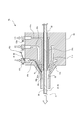
- FIG. 6 is a schematic vertical sectional view of the extruder 82.
- a method for producing the catheter 10 shown in FIGS. 2 and 3 using the extruder 82 will be described below.
- the sheath 16 is formed by extruding the first to third resin materials 121 to 123 that are the main material of the sheath 16 around the core wire 22.
- the core wire 22 is a middle core (mandrel) formed in a cylindrical shape, and is a member that forms the main lumen 20 by being pulled out from the molded sheath 16.
- the peripheral surface of the core wire 22 is optionally subjected to mold release processing.
- the mold release treatment may be performed by optical or chemical surface treatment in addition to the application of a release agent such as fluorine or silicon.
- a release agent such as fluorine or silicon.
- the material of the core wire 22 is not specifically limited, A metal material can be used suitably from a viewpoint of high tensile strength and corrosion resistance. Specific examples include copper or copper alloys, alloy steels such as carbon steel and stainless steel (SUS), nickel or nickel alloys, and the like.
- the inner layer 21 and the blade layer 50 are previously deposited on the peripheral surface of the core wire 22.
- the outer layer 60 is formed by extruding the first to third resin materials 121 to 123 on the surface of the blade layer 50. Thereby, the blade layer 50 is included in the outer layer 60 as shown in FIG.
- the extruder 82 includes a die 83 and flow rate adjusting valves 92a to 92c.
- the die 83 is provided with three channels 91a to 91c for extruding the first to third resin materials 121 to 123 in a molten state.
- the flow rate adjusting valves 92a to 92c can adjust the flow rates of the first to third resin materials 121 to 123 as desired.
- a through hole 97 for inserting the core wire 22 is provided through the axial center of the die 83.
- the core wire 22 is introduced into the through hole 97 at a predetermined speed.
- the feeding direction of the core wire 22 is the left side in the figure as indicated by an arrow in the figure.
- An enlarged diameter portion 94 is formed in the flow path 91a in the vicinity of the upstream side of the discharge port 93a.
- the discharge amount D1 of the first resin material 121 can be stabilized.
- the blade layer 50 provided on the surface of the core wire 22 can be stably covered with the first resin material 121.
- FIG. 6 illustrates the die 83 in which the enlarged diameter portion 94 is formed only in the flow path 91a, the flow paths 91b and 91c may be similarly formed with a cavity near the upstream side of the discharge ports 93b and 93c. Good.
- the discharge port 93 a of the channel 91 a is provided on the inner diameter side closest to the surface of the core wire 22.
- a discharge port 93c of the flow channel 91c and a discharge port 93b of the flow channel 91b are provided in this order.
- the first resin material 121 discharged from the discharge port 93 a is pushed out onto the outer peripheral surface of the core wire 22.
- the 3rd resin material 123 is extruded from the discharge outlet 93c on the outer peripheral surface of the 1st resin material 121, and the 2nd resin material 122 is further extruded from the discharge outlet 93b on it.
- the first to third resin materials 121 to 123 discharged from the flow paths 91a to 91c are formed in a three-layered state by the cavity portion 95 and then molded to a predetermined thickness by the nozzle portion 96 at the tip of the die 83. Then, it is applied to the surface of the core wire 22.
- the first to third resin materials 121 to 123 extruded from the nozzle portion 96 are cooled and cured to form the first to third resin layers 61 to 63, respectively. That is, the outer layer 60 is formed on the surface of the core wire 22 by extruding the first to third resin materials 121 to 123 from the nozzle portion 96 into three layers.
- the operation line 40 is pushed out from the die 83 together with the resin material. More specifically, as shown in FIG. 6, the operation line 40 is pushed out together with the second resin material 122 from the die 83 of the present embodiment through the channel 91 b. As a result, the operation line 40 extending in the longitudinal direction of the sheath 16 is embedded in the outer layer 60.
- the sheath 16 is formed by extruding the first to third resin materials 121 to 123 while increasing the discharge amount D2 of the second resin material 122 relative to the discharge amount D1 of the first resin material 121.
- the discharge amount of the resin material refers to the volume flow rate of the resin material pushed out from the nozzle portion 96 of the die 83 per unit time.
- the outer layer 60 may be formed by extrusion from the distal side to the proximal side, or from the proximal side to the distal side.
- the outer layer 60 in the catheter 10 of the present embodiment has a thickness of the first resin layer 61 from the distal end DE (left side in the figure) toward the proximal end PE (right side in the figure). Gradually decreases, and the thickness of the second resin layer 62 gradually increases. Similarly, the thickness of the third resin layer 63 gradually increases and then decreases.
- the first to third resin layers 61 to 63 are substantially uniform in thickness on the proximal end PE side with respect to the boundary with a predetermined length position from the distal end DE as a boundary.
- the flow rate adjusting valves 92a to 92c of the die 83 are opened and closed, and the discharge amounts D1 to D3 of the first to third resin materials 121 to 123 are adjusted as follows as an example.
- D1 is gradually decreased and D2 and D3 are gradually increased while the first to third resin materials 121 to 123 are nozzled over a predetermined extrusion length L1 (see FIG. 2). Extrude from part 96 (preliminary extrusion process).
- D1 is further gradually decreased, D2 is gradually increased, and the first to third resin materials 121 to 123 are pushed out from the nozzle portion 96 while D3 is gradually increased to gradually decreased.
- the first to third resin materials 121 to 123 are pushed out from the nozzle portion 96 until the extrusion length L2 (see FIG. 2), and the distal end portion 15 is moved. Molding (first extrusion step).
- D1 and D3 are further gradually decreased, and D2 is further gradually increased.
- the discharge amounts D1 to D3 are the first to third resin materials for the drawing speed of the core wire 22 by the take-up machine 86 (see FIG. 5), the opening / closing amounts of the flow rate adjusting valves 92a to 92c of the die 83, or the flow paths 91a to 91c. It can be adjusted by increasing or decreasing the supply pressure of 121 to 123.
- the first, third, and second resin layers 61, 63, and 62 are laminated in this order from the lower layer on the peripheral surface of the core wire 22 to form the outer layer 60.
- the first extrusion process is performed after the preliminary extrusion process in which the molten third resin material 123 into which the operation line 40 is introduced is extruded together with the molten second resin material 122 from the die 83.
- the first to third resin materials 121 to 123 are moved to the die 83 while increasing the discharge amount D2 of the second resin material 122 relative to the discharge amounts D1 and D3 of the first and third resin materials 121 and 123.
- the sheath 16 is formed by extruding together.
- the second resin layer 62 is formed in a thin layer near the distal end DE of the sheath 16 with the discharge amount D2 of the second resin material 122 being non-zero. It is not limited to this. In the preliminary extrusion step, only the first resin material 121 and the third resin material 123 may be extruded.
- dye 83 are opened and closed as follows. It is good to operate.
- the initial (preliminary) extrusion process only the first resin material 121 is extruded over a predetermined length.
- the distal end portion 15 is extruded while gradually decreasing the discharge amount D1 of the first resin material 121 and gradually increasing the discharge amount D2 of the second resin material 122.
- D1 ⁇ D2 At the time of the extrusion length L.
- D1 ⁇ D2 Subsequent to the first extrusion step, D1 ⁇ 0, and only the second resin material 122 is extruded from the nozzle portion 96 to extrude the outer layer 60 to the proximal end PE (second extrusion step).
- the operation line 40 is inserted into the flow path 91b, is guided by the second resin material 122, and is embedded inside the outer layer 60 on the surface layer side.
- the operation line 40 having the tip reaching the cavity part 95 from the flow path 91b is covered with the third resin material 123 and pushed out from the nozzle part 96 in the preforming step.
- the operation line 40 is covered with the second resin material 122 and is pushed out from the nozzle portion 96.
- the operation line 40 is embedded in the third resin layer 63 in the vicinity of the distal end DE of the outer layer 60 of the present embodiment, and the operation line 40 is second on the proximal end PE side. It will be embedded in the resin layer 62.
- the operation line 40 and the outer layer 60 are formed by extruding the outer layer 60 by providing a clearance between the operation line 40 and the second or third resin materials 122 and 123. To prevent close contact. Thereby, in the catheter 10 of this embodiment, the slidability between the operation line 40 and the sub-lumen 30 can be ensured.
- a method of providing a clearance between the operation line 40 and the second or third resin material 122, 123 is not particularly limited. As an example, it is possible to use a molding method in which the filler material 44 is covered around the radial direction of the operation line 40 and inserted into the flow path 91b and extruded together with the third resin material 123 or the second resin material 122.
- a liquid or a soluble solid can be used as the filling material 44.
- the solid filling material 44 include water-soluble or solvent-soluble solid materials such as polyvinyl alcohol (PVA), polyvinyl acetate partial saponified product, polyacrylic acid, polyacrylamide, polyethylene oxide, starch, etc.
- PVA polyvinyl alcohol
- a biodegradable resin can be illustrated.
- the sub-lumen 30 is formed in the outer layer 60, and the sub-lumen 30 and The operation line 40 can be slid.
- the second resin material 122 is blown with a high-pressure gas around the radial direction of the operation line 40. May be extruded.
- the main lumen 20 is formed by pulling out the core wire 22 from the sheath 16 in which the operation wire 40 is slidably inserted into the outer layer 60.
- the interface strength between the core wire 22 and the inner layer 21 is smaller than the peel strength of the outer layer 60 with respect to the blade layer 50 and the inner layer 21. Therefore, by pulling out the core wire 22 from the sheath 16, the inner layer 21 and the blade layer 50 formed on the peripheral surface of the core wire 22 are left in the sheath 16.
- the marker 66 is clamped on the outer periphery of the distal end portion 15 of the sheath 16, and the tip of the operation line 40 is fixed to the marker 66.
- the hydrophilic coat layer 64 is formed in the outer periphery with respect to the partial length of the distal end side among the outer layers 60. As described above, the catheter 10 of the present embodiment can be obtained.
- FIG. 7 is a partial vertical cross-sectional schematic view showing a catheter 10 according to a modification. The figure shows a cross section of the distal end of the catheter 10 cut in the longitudinal direction.
- the first resin layer 61 is provided on the outer peripheral side of the second resin layer 62 with respect to a partial length on the distal end DE side of the sheath 16.
- the second resin layer 62 is formed on the inner side of the first resin layer 61. More specifically, the outer layer 60 is formed by laminating the first resin layer 61, the third resin layer 63, and the second resin layer 62 in this order from the outer peripheral side.
- the thickness of the second resin layer 62 is uniform in the vicinity of the distal end DE of the sheath 16, and the thickness gradually increases from the mid-length position of the distal end portion 15.
- the third resin layer 63 gradually decreases after the thickness gradually increases from the distal end side to the proximal end side of the sheath 16.
- the first resin layer 61 decreases from the distal end side to the proximal end side of the sheath 16.
- the first resin layer 61 is the thickest, and the outer layer 60 is dominated by the thickness and bending rigidity of the first resin layer 61.
- the thickness of the 2nd resin layer 62 and the 3rd resin layer 63 becomes substantially equal in the position of length L2 (> L1) from the distal end DE.
- the second resin layer 62 is the thickest from the position of the length L2 from the distal end DE to the proximal end PE, and the outer layer 60 is dominated by the thickness and bending rigidity of the second resin layer 62.
- the thickness profiles of the first to third resin layers 61 to 63 are the same as those in the above embodiment.
- the first and third resin layers 61 and 63 are laminated in a partial length region in the vicinity of the distal end DE, and the outer peripheral surface thereof is covered with a hydrophilic coat layer 64. Thereby, only the second resin layer 62 is exposed on the outer surface of the sheath 16 exposed to the proximal end side from the coat layer 64. As a result, the first and third resin layers 61, 63 having a lower hardness than the second resin layer 62 are protected by the coat layer 64.
- the periphery of the tip of the operation line 40 is covered with the first resin material 121.
- the resin material around the operation line 40 continuously changes from the first resin material 121 to the third resin material 123 and the second resin material 122 from the distal end side toward the proximal end side.
- the first resin material 121 which is the resin material having the lowest hardness, is laminated on the outermost side of the outer layer 60. That is, in the present modification, the soft first resin material 121 is laminated on the outermost side farthest from the rigid core corresponding to the axis of the main lumen 20 in the vicinity of the distal end DE. For this reason, the flexibility of the sheath 16 when the operation line 40 is pulled is better than that of the above embodiment.
- the sub-lumen 30 may be formed in the inner layer 21 and the blade layer 50 may be provided around the sub-lumen 30.
- the inner layer 21 may have a dominant thickness in the sheath 16, and the inner layer 21 may have a laminated structure including the first to third resin layers 61 to 63.
- the total thickness of the sheath 16 is adjusted to the distal end DE by adjusting the take-up speed by the take-up machine 86 (see FIG. 5) and the extrusion speed of the first to third resin materials 121 to 123. It can be increased from the side toward the proximal end PE side. Thereby, it is possible to sufficiently obtain the bending strength of the catheter 10 at the proximal end portion 17 to which the bending moment is most loaded during the operation while sufficiently securing the flexibility at the distal end portion 15 of the catheter 10.
- three operation lines 40 are slidably inserted into the sub-lumen 30 one by one, but the present invention is not limited to this.
- One, two, or four or more operation lines 40 may be used.
- the number of sub-lumens 30 may be the same as or different from the number of operation lines 40. That is, a plurality of operation lines 40 may be inserted into the sub-lumen 30, or the sub-lumen 30 in which the operation lines 40 are not inserted may be provided in the sheath 16.
Landscapes
- Health & Medical Sciences (AREA)
- Life Sciences & Earth Sciences (AREA)
- Engineering & Computer Science (AREA)
- Animal Behavior & Ethology (AREA)
- Veterinary Medicine (AREA)
- Public Health (AREA)
- General Health & Medical Sciences (AREA)
- Biomedical Technology (AREA)
- Heart & Thoracic Surgery (AREA)
- Biophysics (AREA)
- Hematology (AREA)
- Anesthesiology (AREA)
- Pulmonology (AREA)
- Mechanical Engineering (AREA)
- Surgery (AREA)
- Manufacturing & Machinery (AREA)
- Physics & Mathematics (AREA)
- Nuclear Medicine, Radiotherapy & Molecular Imaging (AREA)
- Optics & Photonics (AREA)
- Pathology (AREA)
- Radiology & Medical Imaging (AREA)
- Medical Informatics (AREA)
- Molecular Biology (AREA)
- Epidemiology (AREA)
- Media Introduction/Drainage Providing Device (AREA)
- Materials For Medical Uses (AREA)
- Rigid Pipes And Flexible Pipes (AREA)
Abstract
Description
カテーテル本体(管状本体)の管腔に貫通されたワイヤ(操作線)は所定の剛性を有しており、これを押し込むことで管状本体の遠位端が屈曲する。ここで、管状本体は、可撓性の異なる4~5個程度の領域が長手方向に並んで段階的に区画形成されており、近位端側ほど剛性が高く、逆に遠位端側ほど柔軟に構成されている。これにより、カテーテルのコシを所定に維持しつつ、ワイヤを押し込んだ際に遠位端部を大きく屈曲させることが可能であるとされている。
このような近年のカテーテルにあっては、上記特許文献1のように管状本体の可撓性を長手方向に複数の領域に段階的に変化させた場合には、操作線による繊細な屈曲操作が困難となる。管状本体の曲げ剛性(断面二次モーメント)は一般に径の4乗に比例するところ、可撓性が段階的に変化する境界部分において管状本体の屈曲性が不連続になるためである。これにより、操作線の押し込みまたは引き出しの長さと、遠位端の屈曲量との関係が複雑化し、遠位端を所望の屈曲量だけ変位させることが困難となる。また、従来のカテーテルにおいて、管状本体の屈曲性が実質的に連続的に変化するよう、長手方向に多数の領域に分割して管状本体の可撓性を徐々に変化させる場合には、使用する材料の種類がきわめて多くなるため成形コストや材料コストに問題がある。
はじめに、本実施形態にかかる製造方法(以下、本方法という場合がある。)により得られるカテーテルの概要を説明し、その後に本方法を詳細に説明する。
図1は、本実施形態のカテーテル10を示す部分縦断面模式図である。同図は、カテーテル10を長手方向に切った先端部の断面を示している。同図の左方がカテーテル10の遠位端(先端)側にあたり、右方が近位端(基端)側にあたる。ただし、同図においては、カテーテル10の近位端側は図示を省略している。
図2は、本実施形態の第一変形例に係るカテーテル10を示す部分縦断面図である。
図3は、図2のIII-III断面図(横断面図)である。
シース16には、メインルーメン20と、メインルーメン20よりも小径のサブルーメン30と、がそれぞれ長手方向に通孔形成されている。操作線40は、サブルーメン30に摺動可能に挿通され、シース16の遠位端部15に先端が固定されている。
図1に示すように、本実施形態のシース16は、ともに樹脂材料からなる第一樹脂層61と、第一樹脂層61よりも硬度の高い第二樹脂層62とを厚み方向に積層してなる。そして、シース16は、第二樹脂層62の厚みが遠位端側から近位端側にむかって増大している。
ここで、カテーテル10の遠位端部15とは、カテーテル10の遠位端DEを含む所定の長さ領域をいう。同様に、カテーテル10の近位端部17(図4を参照)とは、カテーテル10の近位端PEを含む所定の長さ領域をいう。
本実施形態のカテーテル10は、体腔内に挿入された内視鏡に挿通して用いるものである。カテーテル10の遠位端部15を内視鏡の先端から突出させ、体腔内で遠位端部15を屈曲させて所望の向きにカテーテル10を進入させてゆく。
コート層64は、ポリビニルアルコール(PVA)やポリビニルピロリドンなどの親水性の樹脂材料で成形するか、または外表面に潤滑処理が施された樹脂材料で成形されており、少なくとも外表面が親水性である。
また、図2および3に示す変形例にかかるカテーテル10では、径方向の内側から順に第一、第三、第二樹脂層61、63、62をこの順に積層してなる。つまり、外層60において、第一樹脂層61は最内層を構成し、第二樹脂層62は第一樹脂層61よりも外周側に設けられて最外層を構成している。
なお、本実施形態において断りなく「硬度」という場合、ショア硬度を意味している。
同種のポリマーを選択した場合、相互の重合度や架橋度、架橋剤などを変化させることで、第一から第三樹脂材料121~123の硬度を相違させることができる。
第一から第三樹脂材料121~123は、複数種類のポリマーを混合して調製してもよく、または無機のフィラーを添加してもよい。第一から第三樹脂材料121~123は、複数種類のポリマーの混合比率を変えて相互に硬度を相違させてもよく、または添加するフィラーの種類や添加量を変えて相互に硬度を相違させてもよい。
ここで、樹脂層の厚みが単調に減少(増大)するとは、当該樹脂層の厚みが不変または減少(増大)することを意味する。
図1に示すように、遠位端DEから軸方向に長さLの位置において、第一樹脂層61と第二樹脂層62の厚みは略等しくなっている。
したがって、外層60は、遠位端DEから長さLまでは、第一樹脂層61の厚みおよび曲げ剛性が支配的である。そして、遠位端DEから長さLの位置よりも近位端PE側では、第二樹脂層62の厚みおよび曲げ剛性が支配的である。また、外層60の軸方向の中間部から近位端部17(図4を参照)までは、実質的に第二樹脂層62のみで構成されている。
また、長さLよりも近位側にあたる長さL2の位置において、第二樹脂層62と第三樹脂層63の厚みは略等しくなっている。本変形例の場合、長さL、L1、L2の関係は、L1<L<L2である。
外層60は、長さLから長さL2までの間の長さ領域においては、第三樹脂層63と第二樹脂層62の厚みおよび曲げ剛性の和が支配的である。
また、長さL2は長さLよりも大きく、かつ外直径dの25倍以上1400倍以下が好ましく、100倍以上360倍以下がより好ましい。
本実施形態のサブルーメン30は連続した円管状であり、メインルーメン20の中心から所定の半径位置に形成されている。そして、第二樹脂層62の厚みが遠位端側から近位端側にむかって漸増していることにより、図1に示す本実施形態のサブルーメン30の周囲の樹脂材料は、第一樹脂層61(第一樹脂材料121)から第二樹脂層62(第二樹脂材料122)に切り替わっている。また、図2に示す変形例のカテーテル10の場合、サブルーメン30の周囲の樹脂材料は遠位端側から近位端側にむかって第一樹脂層61(第一樹脂材料121)、第三樹脂層63(第三樹脂材料123)、そして第二樹脂層62(第二樹脂材料122)へと切り替わっている。
本実施形態のサブルーメン30は、外層60の内部において、シース16の軸方向に平行な直管状に形成されている。ただし本発明においては、サブルーメン30は直管のほか、メインルーメン20の周囲に螺旋状の曲管として形成してもよい。
操作線40の直径は30~60μmが好ましい。かかる細径ゆえ、操作線40をシース16に対して押し込んだ場合には操作線40は容易に座屈する。このため、本実施形態のカテーテル10は、遠位端部15には実質的に押込力が与えられることはなく、かりに操作線40が遠位端部15から外れたとしても遠位端DEより突き出すことはない。
メインルーメン20の半径は200~300μm程度、内層21の厚さは10~30μm程度、外層60の厚さは100~150μm程度、ブレード層50の厚さは20~30μmである。
カテーテル10の軸心からサブルーメン30の中心までの半径は300~350μm程度、サブルーメン30の内径(直径)は40~100μmとする。
そして、カテーテル10の最外径(半径)は350~450μm程度であり、外直径d(図2を参照)は1mm未満である。このため、本実施形態のカテーテル10は、腹腔動脈などの血管に挿通可能である。
そして、3本の操作線40の牽引長さを個別に制御することにより、カテーテル10の遠位端部15を360度に亘り任意の向きに屈曲させることができる。これにより、カテーテル10の全体を軸回転させるトルク操作をおこなうことなく、操作部70による操作線40の牽引操作のみによって、カテーテル10の進入方向を自在に操作することが可能となる。このため、本実施形態のカテーテル10は、たとえば分岐する血管等の体腔に対して、所望の方向に進入させることが可能である。
また、本実施形態のカテーテル10では、互いに硬度の異なる樹脂層の層厚さを変化させることでシース16の剛性を連続的に変化させている。このため、少ない種類の材料によってシース16を成形することが可能である。
また、外層60の最外層にあたる第二樹脂層62は第一樹脂層61や第三樹脂層63よりも粘着性が低いため、カテーテル10を内視鏡に挿通する際の作業性が良好である。
以下、本実施形態にかかるカテーテルの製造方法(本方法)について詳細に説明する。
本方法は、メインルーメン20およびメインルーメン20よりも小径のサブルーメン30がそれぞれ長手方向に通孔形成されたシース16と、サブルーメン30に摺動可能に挿通された操作線40と、を備えるカテーテル10(図1を参照)の製造方法に関する。
本方法は、溶融状態の第一の樹脂材料(第一樹脂材料121)と、常温で第一樹脂材料121よりも硬度が高く、操作線40が導入された溶融状態の第二の樹脂材料(第二樹脂材料122)と、を、第一樹脂材料121の吐出量D1に対する第二樹脂材料122の吐出量D2を増大させながら、第一および第二樹脂材料121、122をダイ83より共に押し出してシース16を成形する本体成形工程を含む。
押出機82は、第一および第二樹脂材料121、122を投入して、ダイ83よりシース16の外層60を押し出して細線化する装置である。
サイジング装置84は、押出機82より押し出されたシース16を冷却して所定の径に調整する装置であり、一例として水槽を用いることができる。
引取機86は、対向して走行するローラー87からなり、押出機82より押し出されてサイジング装置84で冷却されたシース16の先端を所定の引取速度で引き取る装置である。
製造装置80では、引取機86による引取速度や、サイジング装置84における冷却温度、ダイ83とサイジング装置84との距離などのパラメータを調整することにより、成形されるシース16の径が所望に調整される。
本方法の本体成形工程では、シース16の主材料となる第一から第三樹脂材料121~123を芯線22の周囲に押し出してシース16を成形する。
芯線22は円柱状に形成された中芯(マンドレル)であり、成形されたシース16から引き抜かれることによりメインルーメン20を形成する部材である。
芯線22の材質は特に限定されないが、高い引張強度と耐食性の観点から金属材料を好適に用いることができる。具体的には、銅または銅合金、炭素鋼やステンレス鋼(SUS)などの合金鋼、ニッケルまたはニッケル合金などを挙げることができる。
本体成形工程では、ブレード層50の表面に第一から第三樹脂材料121~123を押し出して外層60を形成する。これにより、図2に示したようにブレード層50は外層60に内包される。
ダイ83には、溶融状態の第一から第三樹脂材料121~123をそれぞれ押し出すための三式の流路91a~91cが設けられている。
流量調整弁92a~92cは、第一から第三樹脂材料121~123の流量を所望に増減調整可能である。
また、ダイ83の軸心には、芯線22を挿通するための通孔97が貫通して設けられている。芯線22は、所定の速度で通孔97に導入される。芯線22の送り方向は、同図に矢印で示すように、図中左方である。
図6では流路91aにのみ拡径部94が形成されたダイ83を例示しているが、流路91bおよび91cに関しても同様に吐出口93bおよび93cの上流側近傍にキャビティを形成してもよい。
これにより、吐出口93aより吐出される第一樹脂材料121は芯線22の外周面上に押し出される。そして、第一樹脂材料121の外周面上には第三樹脂材料123が吐出口93cより押し出され、さらにその上に第二樹脂材料122が吐出口93bより押し出される。
これにより、シース16の長手方向に延在する操作線40が外層60の内部に埋設される。
本方法の本体成形工程では、第一樹脂材料121の吐出量D1に対する第二樹脂材料122の吐出量D2を増大させながら第一から第三樹脂材料121~123を押し出してシース16を成形する。ここで、樹脂材料の吐出量とは、単位時間あたりにダイ83のノズル部96より押し出される当該樹脂材料の体積流量をいう。
図2に示すように、本実施形態のカテーテル10における外層60は、遠位端DE(図中左方)から近位端PE(図中右方)に向かって、第一樹脂層61の厚みは漸減し、第二樹脂層62の厚みは漸増する。同様に、第三樹脂層63の厚みは漸増してから漸減してゆく。そして、第一から第三樹脂層61~63は、遠位端DEから所定の長さ位置を境界として、当該境界よりも近位端PE側に関しては厚みが略均一である。
(1)初期条件をD2=D3≒0として、第一樹脂材料121のみをノズル部96より押し出して遠位端DEを成形する(初期押出工程)。
(2)初期押出工程に続けて、D1を漸減し、D2とD3を漸増しながら、所定の押出長さL1(図2を参照)に亘って第一から第三樹脂材料121~123をノズル部96より押し出す(予備押出工程)。予備押出工程の終期では、D1≒D3>D2である。
(3)予備押出工程に続けて、D1をさらに漸減し、D2を漸増し、D3を漸増から漸減に転じさせながら第一から第三樹脂材料121~123をノズル部96より押し出す。押出長さL(図2を参照)の時点で、D3>D1≒D2である。さらに、D1とD3を漸減し、D2を漸増させながら、押出長さL2(図2を参照)まで、第一から第三樹脂材料121~123をノズル部96より押し出して遠位端部15を成形する(第一押出工程)。第一押出工程の終期では、D2≒D3>D1である。
(4)第一押出工程に続けて、D1とD3をさらに漸減させ、D2をさらに漸増する。そして、D1=D3≒0として、第二樹脂材料122のみをノズル部96より押し出して、外層60を近位端PEまで押出成形する(第二押出工程)。
第一押出工程においては、第一および第三樹脂材料121、123の吐出量D1、D3に対する第二樹脂材料122の吐出量D2を増大させながら第一から第三樹脂材料121~123をダイ83より共に押し出してシース16を成形する。
初期(予備)押出工程では、所定長さに亘り、第一樹脂材料121のみを押し出す。
続けて、第一押出工程では、第一樹脂材料121の吐出量D1を漸減させ、第二樹脂材料122の吐出量D2を漸増させながら、遠位端部15を押出成形する。押出長さLの時点では、D1≒D2である。
第一押出工程に続けて、D1≒0として、第二樹脂材料122のみをノズル部96より押し出して、外層60を近位端PEまで押出成形する(第二押出工程)。
流路91bからキャビティ部95に先端が到達した操作線40は、予備成形工程においては周囲を第三樹脂材料123に覆われてノズル部96より押し出される。そして、第一押出工程および第二押出工程では、操作線40は周囲を第二樹脂材料122に覆われてノズル部96より押し出されることとなる。
これにより、図2に示すように、本実施形態の外層60の遠位端DE近傍においては操作線40が第三樹脂層63に埋設され、近位端PE側においては操作線40が第二樹脂層62に埋設されることとなる。
充填材料44としては、液体、または可溶性の固体を用いることができる。固体の充填材料44の例としては、水溶性または溶剤可溶性の固体材料、具体的には、ポリビニルアルコール(PVA)、ポリ酢酸ビニル部分けん化物、ポリアクリル酸、ポリアクリルアミド、ポリエチレンオキシドまたは澱粉等の生分解性樹脂を例示することができる。
そして、本体成形工程にて外層60の内部に埋設された操作線40の表面より充填材料44を除去することで、外層60の内部にサブルーメン30が通孔形成されるとともに、サブルーメン30と操作線40が摺動可能となる。
操作線40が外層60に対して摺動可能に挿通されたシース16からは、芯線22を引き抜くことによりメインルーメン20が形成される。ここで、離型処理が施された芯線22においては、芯線22と内層21との界面強度が、ブレード層50や内層21に対する外層60の剥離強度よりも小さい。したがって、シース16から芯線22を引き抜くことにより、芯線22の周面に形成されていた内層21およびブレード層50がシース16の内部に残置される。
以上により、本実施形態のカテーテル10を得ることができる。
図7は、変形例に係るカテーテル10を示す部分縦断面模式図である。同図は、カテーテル10を長手方向に切った先端部の断面を示している。
本変形例において、第一樹脂層61は、シース16の遠位端DE側の一部長さについて、第二樹脂層62よりも外周側に設けられている。
第三樹脂層63は、シース16の遠位端側から近位端側にむかって厚みが漸増した後に漸減している。
第一樹脂層61は、シース16の遠位端側から近位端側にむかって減少している。
また、遠位端DEより長さL2(>L1)の位置において、第二樹脂層62と第三樹脂層63の厚みは略等しくなる。
そして、遠位端DEからの長さL2の位置から近位端PEまでは第二樹脂層62が最も厚く、外層60は第二樹脂層62の厚みおよび曲げ剛性が支配的となる。
これにより、コート層64から近位端側に露出するシース16の外表面には、第二樹脂層62のみが露出している。これにより、第二樹脂層62と比較して硬度が低い第一および第三樹脂層61、63が、コート層64によって保護されている。
そして、シース16において内層21を支配的な厚さとし、内層21を第一から第三樹脂層61~63により積層構成としてもよい。
このようにサブルーメン30の外周をブレード層50で保護することにより、操作時に操作線40に過剰な引張力が付与されたとしても操作線40がカテーテル10を突き破って外部に露出してしまうことがない。
これにより、カテーテル10の遠位端部15における屈曲性を十分に確保しつつ、操作時に曲げモーメントがもっとも負荷される近位端部17におけるカテーテル10の曲げ強度を十分に得ることができる。
Claims (10)
- メインルーメンと、前記メインルーメンよりも小径のサブルーメンと、がそれぞれ長手方向に通孔形成された管状本体と、
前記サブルーメンに摺動可能に挿通され、前記管状本体の遠位端部に先端が固定された操作線と、を有し、
前記管状本体は、ともに樹脂材料からなる第一樹脂層および前記第一樹脂層よりも硬度の高い第二樹脂層を厚み方向に積層してなるとともに、前記第二樹脂層の厚みが遠位端側から近位端側にむかって増大していることを特徴とするカテーテル。 - 前記第一樹脂層の厚みが、前記管状本体の遠位端側から近位端側にむかって単調に減少している請求項1に記載のカテーテル。
- 前記第一樹脂層と前記第二樹脂層との間に、前記第一樹脂層と前記第二樹脂層の中間の硬度を有する第三樹脂層が積層されていることを特徴とする請求項1または2に記載のカテーテル。
- 前記第二樹脂層が、前記第一樹脂層よりも外周側に設けられていることを特徴とする請求項1から3のいずれかに記載のカテーテル。
- 前記第二樹脂層を構成する樹脂材料は、前記第一樹脂層を構成する樹脂材料よりも粘着性が低いことを特徴とする請求項4に記載のカテーテル。
- 前記メインルーメンが内部に形成された管状の内層と、前記内層の周囲にワイヤを編成してなるブレード層と、をさらに有するとともに、
前記第一樹脂層が、前記ブレード層に密着して設けられていることを特徴とする請求項1から5のいずれかに記載のカテーテル。 - 前記操作線が挿通された前記サブルーメンが、前記第一樹脂層よりも外周側に通孔形成されていることを特徴とする請求項1から6のいずれかに記載のカテーテル。
- 前記第一樹脂層が、前記管状本体の遠位端側の一部長さについて、前記第二樹脂層よりも外周側に設けられていることを特徴とする請求項1から3のいずれかに記載のカテーテル。
- メインルーメンおよび前記メインルーメンよりも小径のサブルーメンがそれぞれ長手方向に通孔形成された管状本体と、前記サブルーメンに摺動可能に挿通された操作線と、を備えるカテーテルの製造方法であって、
溶融状態の第一の樹脂材料と、
常温で前記第一の樹脂材料よりも硬度が高く、前記操作線が導入された溶融状態の第二の樹脂材料と、を、
前記第一の樹脂材料の吐出量に対する前記第二の樹脂材料の吐出量を増大させながら、前記第一および第二の樹脂材料をダイより共に押し出して前記管状本体を成形する本体成形工程を含む、カテーテルの製造方法。 - 前記操作線が導入された溶融状態の第三の樹脂材料を、溶融状態の前記第二の樹脂材料とともに前記ダイより共に押し出す予備押出工程の後に前記本体成形工程をおこなう請求項9に記載のカテーテルの製造方法であって、
前記本体成形工程において、前記第一および第三の樹脂材料の吐出量に対する前記第二の樹脂材料の吐出量を増大させながら前記第一、第二および第三の樹脂材料を前記ダイより共に押し出して前記管状本体を成形することを特徴とする、カテーテルの製造方法。
Priority Applications (4)
| Application Number | Priority Date | Filing Date | Title |
|---|---|---|---|
| CN201080010987.5A CN102341141B (zh) | 2009-03-09 | 2010-03-05 | 导管及导管的制造方法 |
| EP10750520.8A EP2407199A4 (en) | 2009-03-09 | 2010-03-05 | CATHETER AND MANUFACTURING METHOD FOR THE CATHETER |
| JP2011503674A JP5696659B2 (ja) | 2009-03-09 | 2010-03-05 | カテーテルの製造方法 |
| US13/201,283 US20110295217A1 (en) | 2009-03-09 | 2010-03-05 | Catheter and method of manufacturing catheter |
Applications Claiming Priority (2)
| Application Number | Priority Date | Filing Date | Title |
|---|---|---|---|
| JP2009-054806 | 2009-03-09 | ||
| JP2009054806 | 2009-03-09 |
Publications (1)
| Publication Number | Publication Date |
|---|---|
| WO2010103762A1 true WO2010103762A1 (ja) | 2010-09-16 |
Family
ID=42728058
Family Applications (1)
| Application Number | Title | Priority Date | Filing Date |
|---|---|---|---|
| PCT/JP2010/001532 Ceased WO2010103762A1 (ja) | 2009-03-09 | 2010-03-05 | カテーテルおよびカテーテルの製造方法 |
Country Status (6)
| Country | Link |
|---|---|
| US (1) | US20110295217A1 (ja) |
| EP (1) | EP2407199A4 (ja) |
| JP (1) | JP5696659B2 (ja) |
| KR (1) | KR20110139698A (ja) |
| CN (1) | CN102341141B (ja) |
| WO (1) | WO2010103762A1 (ja) |
Cited By (3)
| Publication number | Priority date | Publication date | Assignee | Title |
|---|---|---|---|---|
| EP2520408A1 (de) * | 2011-05-06 | 2012-11-07 | Novoplast Schlauchtechnik GmbH | In axialer Richtung dauerhaft beliebig verformbares, extrudiertes Kunststoffprofil |
| JP2015033501A (ja) * | 2013-08-09 | 2015-02-19 | 川澄化学工業株式会社 | マイクロカテーテル及びカテーテル器具 |
| WO2025170573A1 (en) * | 2024-02-06 | 2025-08-14 | Paul Jr Ram H | Medical devices for interventional mri and related methods |
Families Citing this family (26)
| Publication number | Priority date | Publication date | Assignee | Title |
|---|---|---|---|---|
| JP6221300B2 (ja) * | 2013-03-28 | 2017-11-01 | 住友ベークライト株式会社 | カテーテルおよびカテーテル操作部 |
| WO2015015887A1 (ja) * | 2013-07-31 | 2015-02-05 | オリンパスメディカルシステムズ株式会社 | カテーテル |
| EP3151897B1 (en) * | 2014-06-09 | 2020-10-07 | Boston Scientific Scimed Inc. | Deliver assist device for guide catheter |
| CN113350656A (zh) | 2016-02-24 | 2021-09-07 | 禾木(中国)生物工程有限公司 | 柔性增强的神经血管导管 |
| CN106521654B (zh) * | 2016-10-21 | 2019-04-12 | 中国科学院大连化学物理研究所 | 中空纤维膜纺丝喷头及制备中空纤维膜的方法 |
| US10589060B2 (en) | 2016-12-21 | 2020-03-17 | Biosense Webster (Israel) Ltd. | Extrusion with preferential bend axis |
| EP3565511B1 (en) | 2017-01-06 | 2023-10-18 | Incept, LLC | Thromboresistant coatings for aneurysm treatment devices |
| KR101871221B1 (ko) | 2017-02-17 | 2018-06-27 | 재단법인 아산사회복지재단 | 다곡률 카테터 및 수술용 의료장치 |
| WO2018180652A1 (ja) * | 2017-03-31 | 2018-10-04 | Hoya株式会社 | 内視鏡用可撓管の製造方法および内視鏡の製造方法 |
| EP3437668A1 (en) * | 2017-06-21 | 2019-02-06 | Abiomed Europe GmbH | Cannula for intravascular blood pump |
| US11395665B2 (en) | 2018-05-01 | 2022-07-26 | Incept, Llc | Devices and methods for removing obstructive material, from an intravascular site |
| JP2021522885A (ja) | 2018-05-01 | 2021-09-02 | インセプト・リミテッド・ライアビリティ・カンパニーIncept,Llc | 血管内部位から閉塞性物質を除去する装置および方法 |
| US11471582B2 (en) | 2018-07-06 | 2022-10-18 | Incept, Llc | Vacuum transfer tool for extendable catheter |
| US11517335B2 (en) | 2018-07-06 | 2022-12-06 | Incept, Llc | Sealed neurovascular extendable catheter |
| EP3865172A4 (en) * | 2018-10-11 | 2022-06-08 | Asahi Intecc Co., Ltd. | Multi-lumen tube for medical use and method for producing same |
| WO2020161811A1 (ja) * | 2019-02-06 | 2020-08-13 | 朝日インテック株式会社 | カテーテル、および、カテーテルの製造方法 |
| DE202019105681U1 (de) * | 2019-10-15 | 2021-01-19 | Kautex Maschinenbau Gmbh | Extrusionstechnik zur Bildung von Kunststoff-Vorformlingen und Schlauchbildungstechnik |
| EP4044906B1 (en) | 2019-10-15 | 2025-03-12 | Kandu Health, Inc. | Systems and methods for multivariate stroke detection |
| US11638637B2 (en) | 2019-12-18 | 2023-05-02 | Imperative Care, Inc. | Method of removing embolic material with thrombus engagement tool |
| JP2023507553A (ja) | 2019-12-18 | 2023-02-24 | インパラティブ、ケア、インク. | 静脈血栓塞栓症を治療するための方法及びシステム |
| US20210315598A1 (en) | 2019-12-18 | 2021-10-14 | Imperative Care, Inc. | Methods of placing large bore aspiration catheters |
| WO2021183444A1 (en) | 2020-03-10 | 2021-09-16 | Imperative Care, Inc. | Enhanced flexibility neurovascular catheter |
| US11207497B1 (en) | 2020-08-11 | 2021-12-28 | Imperative Care, Inc. | Catheter with enhanced tensile strength |
| US20230048388A1 (en) | 2021-08-12 | 2023-02-16 | Imperative Care, Inc. | Robotically driven interventional device |
| CN113846388A (zh) * | 2021-09-23 | 2021-12-28 | 浙江理工大学 | 一种中空石墨烯纤维的制备方法 |
| USD1077996S1 (en) | 2021-10-18 | 2025-06-03 | Imperative Care, Inc. | Inline fluid filter |
Citations (7)
| Publication number | Priority date | Publication date | Assignee | Title |
|---|---|---|---|---|
| JPS6031765A (ja) * | 1983-08-02 | 1985-02-18 | テルモ株式会社 | カテ−テル |
| JPH05345031A (ja) * | 1992-06-16 | 1993-12-27 | Tougou Medeikitsuto Kk | カテーテル |
| JPH09322940A (ja) * | 1996-06-05 | 1997-12-16 | Nippon Zeon Co Ltd | カテーテルチューブ及びバルーンカテーテル |
| JP2001190681A (ja) * | 2000-01-12 | 2001-07-17 | Terumo Corp | カテーテル |
| JP2007507305A (ja) | 2003-10-01 | 2007-03-29 | ミクラス エンドバスキュラー コーポレイション | 方向操作可能なバルーン・カテーテル |
| JP2008125683A (ja) * | 2006-11-17 | 2008-06-05 | Kanazawa Inst Of Technology | カテーテルおよびその製造方法 |
| JP2009054806A (ja) | 2007-08-27 | 2009-03-12 | Canon Inc | 撮像素子及び撮像装置 |
Family Cites Families (8)
| Publication number | Priority date | Publication date | Assignee | Title |
|---|---|---|---|---|
| DE4032869A1 (de) * | 1990-10-17 | 1992-04-23 | Gercke Hans Hermann | Verfahren zur herstellung von kathetern |
| US5221270A (en) * | 1991-06-28 | 1993-06-22 | Cook Incorporated | Soft tip guiding catheter |
| US5533985A (en) * | 1994-04-20 | 1996-07-09 | Wang; James C. | Tubing |
| JPH08252319A (ja) * | 1995-03-15 | 1996-10-01 | Olympus Optical Co Ltd | 可撓管の湾曲機構 |
| US6030369A (en) * | 1997-07-03 | 2000-02-29 | Target Therapeutics Inc. | Micro catheter shaft |
| CA2558796C (en) * | 2004-03-23 | 2016-10-04 | Boston Scientific Limited | In-vivo visualization system |
| JP4790349B2 (ja) * | 2005-08-30 | 2011-10-12 | 株式会社パイオラックスメディカルデバイス | カテーテル |
| US20080234660A2 (en) * | 2006-05-16 | 2008-09-25 | Sarah Cumming | Steerable Catheter Using Flat Pull Wires and Method of Making Same |
-
2010
- 2010-03-05 EP EP10750520.8A patent/EP2407199A4/en not_active Withdrawn
- 2010-03-05 US US13/201,283 patent/US20110295217A1/en not_active Abandoned
- 2010-03-05 WO PCT/JP2010/001532 patent/WO2010103762A1/ja not_active Ceased
- 2010-03-05 CN CN201080010987.5A patent/CN102341141B/zh not_active Expired - Fee Related
- 2010-03-05 KR KR1020117022132A patent/KR20110139698A/ko not_active Withdrawn
- 2010-03-05 JP JP2011503674A patent/JP5696659B2/ja not_active Expired - Fee Related
Patent Citations (7)
| Publication number | Priority date | Publication date | Assignee | Title |
|---|---|---|---|---|
| JPS6031765A (ja) * | 1983-08-02 | 1985-02-18 | テルモ株式会社 | カテ−テル |
| JPH05345031A (ja) * | 1992-06-16 | 1993-12-27 | Tougou Medeikitsuto Kk | カテーテル |
| JPH09322940A (ja) * | 1996-06-05 | 1997-12-16 | Nippon Zeon Co Ltd | カテーテルチューブ及びバルーンカテーテル |
| JP2001190681A (ja) * | 2000-01-12 | 2001-07-17 | Terumo Corp | カテーテル |
| JP2007507305A (ja) | 2003-10-01 | 2007-03-29 | ミクラス エンドバスキュラー コーポレイション | 方向操作可能なバルーン・カテーテル |
| JP2008125683A (ja) * | 2006-11-17 | 2008-06-05 | Kanazawa Inst Of Technology | カテーテルおよびその製造方法 |
| JP2009054806A (ja) | 2007-08-27 | 2009-03-12 | Canon Inc | 撮像素子及び撮像装置 |
Non-Patent Citations (1)
| Title |
|---|
| See also references of EP2407199A4 |
Cited By (3)
| Publication number | Priority date | Publication date | Assignee | Title |
|---|---|---|---|---|
| EP2520408A1 (de) * | 2011-05-06 | 2012-11-07 | Novoplast Schlauchtechnik GmbH | In axialer Richtung dauerhaft beliebig verformbares, extrudiertes Kunststoffprofil |
| JP2015033501A (ja) * | 2013-08-09 | 2015-02-19 | 川澄化学工業株式会社 | マイクロカテーテル及びカテーテル器具 |
| WO2025170573A1 (en) * | 2024-02-06 | 2025-08-14 | Paul Jr Ram H | Medical devices for interventional mri and related methods |
Also Published As
| Publication number | Publication date |
|---|---|
| EP2407199A4 (en) | 2014-08-13 |
| JPWO2010103762A1 (ja) | 2012-09-13 |
| JP5696659B2 (ja) | 2015-04-08 |
| KR20110139698A (ko) | 2011-12-29 |
| US20110295217A1 (en) | 2011-12-01 |
| CN102341141A (zh) | 2012-02-01 |
| CN102341141B (zh) | 2014-10-29 |
| EP2407199A1 (en) | 2012-01-18 |
Similar Documents
| Publication | Publication Date | Title |
|---|---|---|
| JP5696659B2 (ja) | カテーテルの製造方法 | |
| JP5225848B2 (ja) | マイクロカテーテル | |
| JP4924418B2 (ja) | 医療用カテーテルチューブならびにその製造方法 | |
| WO2013128910A1 (ja) | 医療機器の製造方法および医療機器 | |
| EP2732842B1 (en) | Method of producing catheter tube | |
| JP5990907B2 (ja) | 医療機器および医療機器の製造方法 | |
| JP5233156B2 (ja) | 医療用カテーテルチューブ | |
| JP2010227137A (ja) | カテーテル | |
| JP2010207321A (ja) | カテーテル | |
| JP5817538B2 (ja) | 押出成形品の製造方法及び押出成形装置 | |
| JP5834536B2 (ja) | 内腔と外周が異なるテーパー構造を有するカテーテル | |
| JP5239993B2 (ja) | カテーテルの製造方法 | |
| JP2008092969A (ja) | 医療用マルチルーメンチューブ | |
| JPH11197249A (ja) | カテーテルチューブの製造方法 | |
| JP2006051080A (ja) | 医療用カテーテルチューブならびにその製造方法 | |
| JP2001327603A (ja) | 可撓性チューブの製造方法 | |
| WO2014203343A1 (ja) | 医療機器および医療機器の製造方法 | |
| JP2006051081A (ja) | 医療用カテーテルチューブならびにその製造方法 | |
| JP4274018B2 (ja) | カテーテルチューブとその製造方法およびカテーテル | |
| JP5446488B2 (ja) | カテーテルの製造方法 | |
| JP2006288943A (ja) | 医療用カテーテルチューブならびにその製造方法 | |
| JP6137380B2 (ja) | 医療機器の製造方法 | |
| JP2014100327A (ja) | カテーテル用チューブの製造方法 | |
| JP5212092B2 (ja) | カテーテルの製造方法 | |
| JP2006158878A (ja) | 医療用カテーテルチューブならびにその製造方法 |
Legal Events
| Date | Code | Title | Description |
|---|---|---|---|
| WWE | Wipo information: entry into national phase |
Ref document number: 201080010987.5 Country of ref document: CN |
|
| 121 | Ep: the epo has been informed by wipo that ep was designated in this application |
Ref document number: 10750520 Country of ref document: EP Kind code of ref document: A1 |
|
| ENP | Entry into the national phase |
Ref document number: 2011503674 Country of ref document: JP Kind code of ref document: A |
|
| WWE | Wipo information: entry into national phase |
Ref document number: 13201283 Country of ref document: US |
|
| NENP | Non-entry into the national phase |
Ref country code: DE |
|
| WWE | Wipo information: entry into national phase |
Ref document number: 2010750520 Country of ref document: EP |
|
| ENP | Entry into the national phase |
Ref document number: 20117022132 Country of ref document: KR Kind code of ref document: A |