WO2010109984A1 - 放射線画像検出システム - Google Patents
放射線画像検出システム Download PDFInfo
- Publication number
- WO2010109984A1 WO2010109984A1 PCT/JP2010/052400 JP2010052400W WO2010109984A1 WO 2010109984 A1 WO2010109984 A1 WO 2010109984A1 JP 2010052400 W JP2010052400 W JP 2010052400W WO 2010109984 A1 WO2010109984 A1 WO 2010109984A1
- Authority
- WO
- WIPO (PCT)
- Prior art keywords
- charging
- battery
- cable
- image detection
- cradle
- Prior art date
- Legal status (The legal status is an assumption and is not a legal conclusion. Google has not performed a legal analysis and makes no representation as to the accuracy of the status listed.)
- Ceased
Links
Images


Classifications
-
- H—ELECTRICITY
- H10—SEMICONDUCTOR DEVICES; ELECTRIC SOLID-STATE DEVICES NOT OTHERWISE PROVIDED FOR
- H10F—INORGANIC SEMICONDUCTOR DEVICES SENSITIVE TO INFRARED RADIATION, LIGHT, ELECTROMAGNETIC RADIATION OF SHORTER WAVELENGTH OR CORPUSCULAR RADIATION
- H10F39/00—Integrated devices, or assemblies of multiple devices, comprising at least one element covered by group H10F30/00, e.g. radiation detectors comprising photodiode arrays
- H10F39/80—Constructional details of image sensors
- H10F39/802—Geometry or disposition of elements in pixels, e.g. address-lines or gate electrodes
-
- A—HUMAN NECESSITIES
- A61—MEDICAL OR VETERINARY SCIENCE; HYGIENE
- A61B—DIAGNOSIS; SURGERY; IDENTIFICATION
- A61B6/00—Apparatus or devices for radiation diagnosis; Apparatus or devices for radiation diagnosis combined with radiation therapy equipment
- A61B6/42—Arrangements for detecting radiation specially adapted for radiation diagnosis
- A61B6/4208—Arrangements for detecting radiation specially adapted for radiation diagnosis characterised by using a particular type of detector
- A61B6/4233—Arrangements for detecting radiation specially adapted for radiation diagnosis characterised by using a particular type of detector using matrix detectors
-
- A—HUMAN NECESSITIES
- A61—MEDICAL OR VETERINARY SCIENCE; HYGIENE
- A61B—DIAGNOSIS; SURGERY; IDENTIFICATION
- A61B6/00—Apparatus or devices for radiation diagnosis; Apparatus or devices for radiation diagnosis combined with radiation therapy equipment
- A61B6/42—Arrangements for detecting radiation specially adapted for radiation diagnosis
- A61B6/4283—Arrangements for detecting radiation specially adapted for radiation diagnosis characterised by a detector unit being housed in a cassette
-
- A—HUMAN NECESSITIES
- A61—MEDICAL OR VETERINARY SCIENCE; HYGIENE
- A61B—DIAGNOSIS; SURGERY; IDENTIFICATION
- A61B6/00—Apparatus or devices for radiation diagnosis; Apparatus or devices for radiation diagnosis combined with radiation therapy equipment
- A61B6/56—Details of data transmission or power supply, e.g. use of slip rings
-
- H—ELECTRICITY
- H04—ELECTRIC COMMUNICATION TECHNIQUE
- H04N—PICTORIAL COMMUNICATION, e.g. TELEVISION
- H04N23/00—Cameras or camera modules comprising electronic image sensors; Control thereof
- H04N23/30—Cameras or camera modules comprising electronic image sensors; Control thereof for generating image signals from X-rays
-
- H—ELECTRICITY
- H04—ELECTRIC COMMUNICATION TECHNIQUE
- H04N—PICTORIAL COMMUNICATION, e.g. TELEVISION
- H04N25/00—Circuitry of solid-state image sensors [SSIS]; Control thereof
- H04N25/30—Circuitry of solid-state image sensors [SSIS]; Control thereof for transforming X-rays into image signals
Definitions
- the present invention relates to a radiation image detection system.
- a radiation image detection apparatus in which a solid-state imaging element called a so-called flat panel detector (FPD) is two-dimensionally arranged is known.
- a radiation image detection apparatus radiation energy is directly converted into charges using a photoconductive substance such as a-Se (amorphous selenium) as a radiation detection element, and the charges are arranged two-dimensionally.
- a direct readout method that reads out electrical signals pixel by pixel using a signal readout switch element such as a TFT (Thin Film Transistor), or radiation energy is converted into light by a scintillator, etc., and this light is arranged two-dimensionally.
- TFT Thintillator
- JP 2001-224579 A Japanese Patent Laid-Open No. 6-342099 Japanese Patent No. 3302163
- the present invention has been made in view of the above circumstances.
- high-speed charging with a large current is possible. It is an object of the present invention to provide a radiation image detection system that does not cause deterioration of the image.
- the radiation image detection system of the present invention is: A cassette-type radiation image detection device that incorporates a battery that supplies power to each functional unit, and can be driven by power supply from the battery; A charge control circuit for performing charge control of the battery; A cradle configured to be able to supply power to the radiation image detection device from the outside by placing the radiation image detection device; A cable capable of supplying power to the radiological image detection device from the outside by connecting to the radiological image detection device; The radiological image detection device includes a connection unit configured to be electrically connectable to each of the cradle and the cable and receiving power, Charging of the battery is made possible by both connection by the cradle and connection by the cable, The charging control circuit switches a charging current between connection by the cradle and connection by the cable.
- the cable can be thinned, and the manageability of the radiation image detecting apparatus is improved.
- the current flowing through the cable and the charge control circuit can be reduced, the power loss corresponding to the voltage drop caused by the cable can be reduced, heat generation in the charge control circuit is reduced, and noise from the charge control circuit is reduced. Can be suppressed. As a result, it is possible to suppress deterioration in image quality due to the influence of heat and noise.
- the battery when connected to the cradle, the battery can be charged with a large current, and an effect is obtained that charging in a short time is possible.
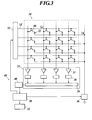
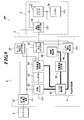
- FIG. 2 is an equivalent circuit diagram illustrating configurations of a sensor panel unit and a reading unit of the radiological image detection apparatus illustrated in FIG. 1.
- FIG. 1 is a principal part block diagram which shows schematic structure of the charge control circuit in FIG.
- explanatory drawing shows the state which connected the radiographic image detection apparatus shown in FIG. 1 to the cradle.
- explanatory drawing which shows the state which connected the cable to the radiographic image detection apparatus shown in FIG.
- the radiation image detection system 1 includes a radiation image detection device 2, a cradle 4 on which the radiation image detection device 2 is placed, and a cable connected to the radiation image detection device 2. And 5.
- the cradle 4 is configured to be able to supply power to the radiation image detection device 2 from the outside by mounting the radiation image detection device 2, and as shown in FIG. 4, an outlet connected to an external power source (not shown). 8 is connected to the AC / DC constant voltage power supply 41, and an output connector unit that outputs the power supplied from the AC / DC constant voltage power supply 41 to the outside.
- the AC / DC constant voltage power supply 41 outputs power at a constant voltage regardless of load fluctuations, and the output connector supplies power to the radiation image detection apparatus 2 at this predetermined voltage. It is supposed to be.
- the cradle 4 has, as the output connector portion, a cradle output connector portion 42 that is connected to the detection device side connector portion 26 when the radiation image detection device 2 is placed on the cradle, and a detection device side connector portion. 26 is provided with a cable output connector 43 to which the cable 5 connected to 26 is connected.
- the cradle output connector portion 42 is electrically connected to the detection device side connector portion 26 of the radiation image detection device 2, and the radiation image is supplied from the AC / DC constant voltage power supply 41. Electric power is supplied directly to the detection device 2. Further, when the cable 5 connected to the cable output connector portion 43 is connected to the detection device side connector portion 26, power is supplied from the AC / DC constant voltage power supply 41 to the radiation image detection device 2 via the cable 5. .
- the cable 5 can supply power to the radiological image detection apparatus 2 from the outside by being connected to the radiographic image detection apparatus 2.
- the cable 5 has one end connected to the detection device side connector 26 of the radiation image detection device 2 and the other end connected to the cable output connector 43 of the cradle 4.
- power is supplied from the AC / DC constant voltage power supply 41 to the radiation image detection apparatus 2.
- the cable 5 is connected to an external power supply via the cradle 4 is shown, but the method of connecting the cable 5 and the external power supply is not limited to this, and the cable 5 is connected to the cradle 4. It may be configured to be directly connected to an AC / DC constant voltage power supply outside the power supply and to supply power to the radiation image detection apparatus 2 from the external power supply.
- the thickness of the cable 5 is not particularly limited, but in this embodiment, it is assumed that shooting is performed with the cable 5 connected, so that the diameter of the cable 5 is as thin as possible and is easy to handle. Is preferred.
- the diameter of the cable 5 is thin, the current capacity that can be supplied is reduced, but the power loss corresponding to the voltage drop in the cable 5 can be reduced accordingly.
- the current capacity that can be supplied is small, the heat generation in the charge control circuit 6 to be described later is reduced, and image quality deterioration due to the influence of heat can be suppressed.
- the amount of noise generated from the charging control circuit 6 can be suppressed.
- the radiation image detection apparatus 2 is a portable cassette type FPD in which a so-called flat panel detector (hereinafter referred to as “FPD”) is configured in a cassette type, and is used for radiographic imaging.
- Image data (hereinafter simply referred to as “image data”) is acquired.
- a so-called indirect radiation image detection device that includes a scintillator or the like and converts the emitted radiation into electromagnetic waves of other wavelengths such as visible light to obtain an electrical signal will be described as the radiation image detection device 2.
- the present invention can also be applied to a so-called direct radiation image detection apparatus that directly detects radiation with a radiation detection element without using a scintillator or the like.
- the radiation image detection apparatus 2 includes a battery 28, a battery driving state in which power is acquired from only the battery 28 and each functional unit is driven, and the cradle 4 or Two driving states, an external power feeding driving state driven by power feeding from the outside via the cable 5, can be selected.
- the battery 28 is driven in parallel with the driving of each functional unit. It is comprised so that it can charge.
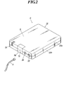
- FIG. 2 is a perspective view of the radiation image detection apparatus 2 in the present embodiment.
- the radiation image detection apparatus 2 includes a housing 21 that protects the inside.
- the housing 21 has at least a surface X on which radiation is received (hereinafter referred to as a radiation incident surface X) formed of a material such as a carbon plate or plastic that transmits radiation.
- FIG. 2 shows a case where the casing 21 is formed of a front member 21a and a back member 21b.
- the shape and configuration are not particularly limited. It is also possible to form a cylindrical so-called monocoque shape.
- a power switch 22, an indicator 25, a detection device side connector portion 26, and the like are arranged on the side surface portion of the radiation image detection device 2.
- the power switch 22 switches ON / OFF of the power supply of the radiation image detection apparatus 2, and each function unit of the radiation image detection apparatus 2 by a battery 28 (see FIG. 1) described later by operating the power switch 22.
- a signal for instructing the start and stop of the power supply is output to the control unit 30 (see FIG. 1) described later.
- the power consumption of the battery 28 can be suppressed by turning off the power (that is, stopping the power supply to each functional unit by the battery 28).
- the indicator 25 is composed of, for example, an LED or the like, and displays the remaining amount of charge of the battery 28 and various operation statuses.
- the radiation image detection device 2 is provided with a battery 28 that supplies power to each functional unit of the radiation image detection device 2.
- the battery 28 is rechargeable, for example, a rechargeable secondary battery such as a nickel cadmium battery, a nickel metal hydride battery, a lithium ion battery, a small sealed lead battery, a lead storage battery, an electric double layer capacitor, a lithium ion capacitor (LIC). ) And the like can be applied.
- a lithium ion capacitor is particularly preferable because it is excellent in power storage efficiency, can be charged at high speed with a large current (for example, 5 to 10 amperes), and can greatly shorten the charging time.
- a lid member 70 that is opened and closed for replacement of the battery 28 built in the housing 21 is provided on a side surface portion of the radiation image detection apparatus 2.
- An antenna device 71 is embedded for the image detection device 2 to transmit and receive information to and from the outside via a wireless access point 113 (see FIG. 5) described later.
- the detection device side connector portion 26 is configured to be electrically connectable to each of the cradle 4 and the cable 5 and receives power supplied from the outside to the radiation image detection device 2. It is a connection part. As will be described later, when the cradle output connector portion 42 of the cradle 4 is connected to the detection device side connector portion 26, it is possible to supply a large current to the battery 28 and perform rapid charging. In addition, when the cable 5 is connected to the detection device side connector portion 26, the battery 28 can be charged while driving each functional portion with electric power supplied from the outside.
- a connection detection unit 60 is provided between the battery 28 and the detection device side connector unit 26.
- the connection detection unit 60 is a detection unit that detects whether the cradle 4 or the cable 5 is connected to the detection device side connector unit 26.
- the detection result by the connection detection unit 60 is output to the charging current setting unit 61 of the charging control circuit 6.
- the method for detecting whether the connection detection unit 60 is connected to the detection device side connector unit 26 is the cradle 4 or the cable 5 is not particularly limited.
- a mechanical switch (not shown) is provided in the detection device side connector portion 26 so that the ON / OFF state of the switch is switched between when the cradle 4 is connected and when the cable 5 is connected.
- a contact point for detection may be provided, and the short-circuit / open state of the contact point may be changed between when the cradle 4 is connected and when the cable 5 is connected.
- a power supply circuit 29 (see FIG. 1) is provided between the battery 28 and each functional unit.
- the power supply circuit 29 is a functional unit that appropriately converts and adjusts the current value and the like so that the power supplied from the battery 28 is suitable for each functional unit of the supply destination.
- a scintillator layer (not shown) that absorbs radiation incident from the radiation incident surface X and converts it into light having a wavelength including visible light is formed inside the radiation incident surface X (see FIG. 2) of the housing 21.
- the scintillator layer for example, a layer formed by using a phosphor in which a luminescent center substance is activated in a mother body such as CsI: Tl, Gd 2 O 2 S: Tb, ZnS: Ag, or the like can be used.
- a plurality of photoelectric conversion elements 23 that convert light output from the scintillator layer into electric signals are two-dimensionally provided on the surface of the scintillator layer opposite to the surface on which radiation is incident.
- a sensor panel unit 24 is provided as the arranged detection means.
- the photoelectric conversion element 23 is, for example, a photodiode, and constitutes a radiation detection element that converts the radiation transmitted through the subject into an electrical signal together with the scintillator layer and the like.
- a reading unit 45 that is a reading unit that reads the output value of each photoelectric conversion element 23 of the sensor panel unit 24 by the control unit 30, the scanning drive circuit 32, the signal reading circuit 33, and the like. Is configured.
- each photoelectric conversion element 23 of the sensor panel unit 24 is connected to a source electrode of a TFT 46 which is a signal reading switch element.
- a bias line Lb is connected to the other electrode of each photoelectric conversion element 23, and the bias line Lb is connected to a bias power supply 36, and a reverse bias voltage is applied from the bias power supply 36 to each photoelectric conversion element 23. It has come to be.
- each TFT 46 is connected to a scanning line Ll extending from the scanning drive circuit 32, and a read voltage (ON voltage) or OFF voltage is applied to the gate electrode of the TFT 46 from a TFT power source (not shown) via the scanning line Ll. Is applied.
- the drain electrode of each TFT 46 is connected to the signal line Lr.
- Each signal line Lr is connected to an amplifier circuit 37 in the signal readout circuit 33, and an output line of each amplifier circuit 37 is connected to an analog multiplexer 39 via a sample hold circuit 38.
- the signal readout circuit 33 is connected to an A / D converter 40 as processing means for converting the signal into a digital signal.
- the analog image signal sent from the analog multiplexer 39 is an A / D converter.
- the signal readout circuit 33 is connected to the control unit 30 via the A / D conversion unit 40, and a digital image signal is output to the control unit 30.
- a storage unit 31 is connected to the control unit 30, and the control unit 30 stores the digital image signal sent from the A / D conversion unit 40 in the storage unit 31 as image data.
- the control unit 30 is a computer that includes a CPU (Central Processing Unit), a ROM (Read Only Memory), a RAM (Random Access Memory), and the like (not shown), and controls the radiation image detection apparatus 2 as a whole.
- the signal processing unit 34 is a functional unit that converts the image data into data in a format suitable for output to the outside by performing predetermined signal processing on the image data.
- the ROM stores a program for performing various processes in the radiation image detection apparatus 2 such as a real image data generation process, an offset correction value generation process, and a power supply control process, and various control programs and parameters.
- the control unit 30 reads a predetermined program stored in the ROM, develops it in a work area of the RAM, and the CPU executes various processes according to the program.
- the storage unit 31 is configured by, for example, an HDD (Hard Disk Drive), a flash memory, or the like.
- the storage unit 31 includes actual image data generated by the reading unit 45 (see FIG. 3) (radiation transmitted through the subject). Based image data), dark read values (image data acquired without radiation), and the like are stored.
- the storage unit 31 may be a built-in memory or a removable memory such as a memory card.
- the capacity is not particularly limited, but preferably has a capacity capable of storing a plurality of pieces of image data.
- the communication unit 35 is connected to the antenna device 71, and transmits / receives various signals to / from an external device such as the console 101 under the control of the control unit 30.
- the communication unit 35 communicates with an external device such as the console 101 in a wireless manner via the wireless access point 113.
- the communication unit 35 transmits image data based on an image signal read by the reading unit 45 and converted from an analog signal to a digital signal by the A / D conversion unit 40 to the console 101 which is an external device and the console.
- the radiographing order information is received from 101 and the like.
- the charging control circuit 6 is a functional unit that controls a charging current supplied to the battery 28 when the battery 28 is charged.
- FIG. 4 is a principal block diagram showing the configuration of the charging control circuit 6 in the present embodiment. As shown in FIG. 4, in the present embodiment, the charging control circuit 6 includes a charging current setting unit 61, a switch control unit 62, a charging switch 63, an inductor 64, a charging current detection unit 65, and a battery voltage detection unit 66. Yes.
- the charging current setting unit 61 is a functional unit that switches the charging current supplied to the battery 28 according to the detection result by the connection detection unit 60.
- the current value of the charging current supplied to the battery 28 is set high, and high-speed charging with a large current is performed. To do.
- the current value of the current supplied to the battery 28 is set low, and charging is performed with a small current. In this case, while the battery 28 is being charged, photographing or the like can be performed in parallel with the battery 28, and the power supplied from the external power source via the cable 5 is not limited to the battery 28.
- the power supply circuit 29 is also supplied to each functional unit.
- the battery voltage detection unit 66 is a functional unit that detects the voltage of the battery 28. The detection result detected by the battery voltage detection unit 66 is output to the switch control unit 62.
- the charging current detection unit 65 is a functional unit that detects the current value of the charging current supplied to the battery 28 for charging when the battery 28 is charged.
- the charging current detector 65 detects a change in the current value of the current supplied to the battery 28 and outputs the change to the switch controller 62.
- the switch controller 62 As will be described later, in this embodiment, when the battery 28 is charged, if constant current charging is performed to some extent, switching to constant voltage charging is performed. However, when the charging method is switched from constant current charging to constant voltage charging. The current flowing through the battery 28 gradually decreases with the passage of time.
- the charging current detector 65 detects the change in the current value and outputs it to the switch controller 62.
- the charging switch 63 is a switch that controls a charging current or a charging voltage for the battery 28.
- constant current charging is performed in which the battery 28 is charged by supplying a current having a predetermined current value.
- the voltage of the battery 28 gradually increases as time elapses. That is, charging is performed while gradually increasing the voltage in order to maintain a constant current value.
- the voltage of the battery 28 exceeds a predetermined voltage, if constant current charging is continued as it is, the current flows too much and the capacity is exceeded.
- the charging switch 63 is a functional unit that performs such switching under the control of the switch control unit 62.
- the type of the charging switch 63 an FET is generally used.
- the charging switch 63 may be composed of an electromagnetic switch (electromagnetic relay), a semiconductor switch (SSR), a photoelectric switch (Photo relay), or the like.
- the switch control unit 62 is a functional unit that controls the charging switch 63.
- the switch control unit 62 is connected to the battery voltage detection unit 66, performs constant current charging until the voltage of the battery 28 reaches a predetermined value (threshold), and switches to constant voltage charging when the voltage exceeds a predetermined value.
- the charging switch 63 is controlled. Further, when the battery 28 is fully charged by performing constant voltage charging, the switch control unit 62 controls to turn off the charging switch 63 and stop the charging of the battery 28.
- the detection result is output from the charging current detection unit 65 to the switch control unit 62, and the switch control unit 62 detects the detection from the charging current detection unit 65. Based on the result, it is determined that the charging is completed when the current almost stops flowing (when the current becomes equal to or lower than a predetermined threshold), and the charging switch 63 is turned off.
- an inductor 64 is provided in the charging control circuit 6, and a current sent from the AC / DC constant voltage power supply is supplied to the battery 28 via the inductor 64.
- the inductor 64 smoothes the voltage and current turned ON / OFF by the charging switch 63.
- a battery switch 67 for switching ON / OFF of charging of the battery 28 is provided between the charging control circuit 6 and the battery 28.
- the battery switch 67 has a function of preventing inflow of current from other than the charging control circuit 6 to the battery 28 and cutting off the connection between the battery 28 and the load during charging and overdischarge.
- this radiographic image detection system 1 is arrange
- the radiographic image capturing system 100 includes, for example, the radiographic image detection system 1 and a console 101 that can communicate with the radiographic image detection device 2 constituting the radiographic image detection system 1.
- the radiological image detection apparatus 2 is provided, for example, in an imaging room R1 that performs imaging of a subject (an imaging target site of the patient M) that is a part of the patient M by irradiating radiation.
- the console 101 is provided corresponding to the photographing room R1.
- a case where one radiographing room R1 is provided in the radiographic imaging system and three radiographic image detection devices 2 are arranged in the radiographic room R1 will be described as an example.
- the number of imaging rooms and the number of radiation image detection devices 2 provided in each imaging room are not limited to the illustrated example.
- the console 101 may not be provided corresponding to each shooting room R1, and one console 101 may be associated with the plurality of shooting rooms R1. Good.
- a bucky device 110 having a cassette holding unit 111 capable of loading and holding the radiographic image detection device 2, a radiation source such as an X-ray tube that irradiates the subject (the imaging target site of the patient M)
- a radiation generator 112 is provided which comprises (not shown).
- the cassette holding unit 111 is for loading the radiation image detection device 2 at the time of imaging.
- FIG. 5 shows an example in which one each of the bucky device 110a for standing position shooting and the bucky device 110b for standing position shooting are provided in the shooting room R1, but in the shooting room R1.
- the number of the bucky devices 110 provided in is not particularly limited.
- one radiation generation device 112 is provided corresponding to each Bucky device 110 is illustrated, but for example, one radiation generation device 112 is provided in the imaging room R1.
- One radiation generation device 112 may correspond to a plurality of the bucky devices 110, and may be used by appropriately moving the position or changing the radiation irradiation direction.
- the radiographing room R1 is a room for shielding radiation and radio waves for radio communication are also blocked, the radiographic image detection apparatus 2 and an external device such as the console 101 communicate in the radiographing room R1.
- a wireless access point (base station) 113 for relaying these communications.
- a front room R2 is provided adjacent to the photographing room R1.
- a radiographer, a doctor, etc. (hereinafter referred to as an “operator”) control the tube voltage, tube current, irradiation field stop, etc. of the radiation generator 112 that irradiates the subject with radiation.
- An operation device 114 for operating the device 110 is disposed.
- a control signal for controlling the radiation irradiation condition of the radiation generating device 112 is transmitted from the console 101 to the operation device 114, and the radiation irradiation condition of the radiation generating device 112 is transmitted to the console 101. It is set according to the control signal from.
- radiation irradiation conditions include exposure start / end timing, radiation tube current value, radiation tube voltage value, filter type, and the like.
- An exposure instruction signal for instructing radiation exposure is transmitted from the operation device 114 to the radiation generation apparatus 112.
- the radiation generation apparatus 112 applies predetermined radiation according to the exposure instruction signal for a predetermined time, Irradiation is performed at a predetermined timing.
- the console 101 is a computer including a control unit configured by a CPU (Central Processing Unit), a storage unit, an input unit, a display unit, a communication unit (all not shown), and the like.
- the console 101 displays an image based on the image data sent from the radiation image detection apparatus 2 on the display unit, or performs various image processing on the image data.
- the console 101 is connected to external devices such as the HIS / RIS 121, the PACS server 122, and the imager 123 via the network N.
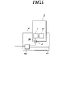
- FIG. 6 is a diagram schematically showing a state in which the radiation image detection device 2 is mounted on the cradle 4.
- the connection detection unit 60 detects that the cradle output connector unit 42 is connected to the detection device side connector unit 26.
- the detection result by the connection detection unit 60 is output to the charging current setting unit 61 of the charging control circuit 6 provided in the radiation image detection device 2.
- the charging current setting unit 61 sets the current value of the charging current supplied to the battery 28 to 2 amperes, for example, so as to charge the battery 28 with a large current. Set to a large current.
- the setting result by the charging current setting unit 61 is output to the switch control unit 62.
- the switch control unit 62 outputs the detection result of the voltage of the battery 28 from the battery voltage detection unit 66, and outputs the current value of the charging current flowing into the battery 28 from the charging current detection unit 65.
- the switch control unit 62 determines whether or not the battery 28 needs to be charged based on the results output from the battery voltage detection unit 66 and the charging current detection unit 65.
- the charging switch 63 is controlled so that charging is performed at a current value (for example, 2 amperes) set in the charging current setting unit 61.
- a constant current charging for example, 2 amperes, which is a set current value).
- the battery voltage detection unit 66 and the charging current detection unit 65 output detection results to the switch control unit 62 as needed, and the switch control unit 62 performs constant current charging and constant voltage based on the detection results. It is always determined whether to charge, whether to continue or end charging.
- the switch control unit 62 controls the charging switch 63 so as to switch from constant current charging to constant voltage charging.
- the switch control unit 62 determines that the charging should be terminated, and performs control for switching the charging switch 63 to OFF. Thereby, charging of the battery 28 is completed.
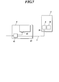
- FIG. 7 is a diagram schematically showing a state in which the cable 5 is connected to the radiation image detection apparatus 2.
- the connection detection section 60 detects that fact.
- the detection result by the connection detection unit 60 is output to the charging current setting unit 61 of the charging control circuit 6.
- the charging current setting unit 61 changes the current value of the charging current to a small value such as 0.1 ampere so as to charge the battery 28 with a small current. Set to current.
- the setting result by the charging current setting unit 61 is output to the switch control unit 62.
- the switch control unit 62 outputs the detection result of the voltage of the battery 28 from the battery voltage detection unit 66, and outputs the current value of the charging current flowing into the battery 28 from the charging current detection unit 65.
- the switch control unit 62 determines whether or not the battery 28 needs to be charged based on the results output from the battery voltage detection unit 66 and the charging current detection unit 65.
- the charging switch 63 is controlled so that charging is performed at the current value (for example, 0.1 ampere) set in the setting unit 61. Thereby, constant current charging at a current value of 0.1 ampere is started.
- imaging and data processing can be performed in parallel with the charging of the battery 28, and the radiation image detection device 2 can be connected to the radiation image detection device 2 from the battery 28 or from the external power source via the detection device side connector 26.
- Electric power is supplied to each functional unit. Note that, when photographing or the like is performed while charging, the supplied current value increases as power is supplied to each functional unit in parallel.
- the battery voltage detection unit 66 and the charging current detection unit 65 output detection results to the switch control unit 62 as needed, and the switch control unit 62 performs constant current charging and constant voltage based on the detection results. It is always determined whether to charge, whether to continue or end charging.
- the switch control unit 62 controls the charging switch 63 so as to switch from constant current charging to constant voltage charging. Further, when the current value output from the charging current detection unit 65 becomes equal to or less than a predetermined value, the switch control unit 62 determines that the charging should be terminated, and performs control for switching the charging switch 63 to OFF. Thereby, the battery 28 charging ends.
- the cradle output connector portion 42 when the cradle output connector portion 42 is connected to the detection device side connector portion 26, high-speed charging can be performed with a large current, and the cable 5 is connected. Can perform processing such as photographing while charging with a small current.
- the charging current is reduced, so that the current capacity of the cable 5 can be reduced and the cable 5 can be thinned. Thereby, the handling property of the radiation image detection apparatus 2 is improved, and it is possible to easily perform imaging or the like without charging the battery 28 while charging the battery 28.
- the current flowing through the cable 5 is reduced, the power loss corresponding to the voltage drop caused by the cable 5 can be reduced.
- the cradle 4 is provided with the cradle output connector portion 42 and the cable output connector portion 43 separately.
- the configuration of the output connector portion on the cradle 4 side is not limited to this.
- the cradle 4 may be provided with a single output connector portion 44 that is used for both connection by attachment to the cradle 4 and connection by the cable 5.
- the processing when is connected is not limited to this.
- the radiographic image is not charged. You may comprise so that supply with respect to the battery 28 of the electric power received from the external power supply may be controlled according to the operating state of each function part of the detection apparatus 2.
- the radiological image detection apparatus 2 is configured to communicate with an external apparatus such as the console 101 in a wireless manner via the antenna apparatus 71.
- a communication connector unit is provided, When a communication cable is connected to the cable, it may be configured to be able to communicate with an external device in a wired manner.
- the power supply connector portions (the detection device side connector portion 26, the cradle output connector portion 42, and the cable output connector portion 43) may also serve as a communication connector portion.
- the operation device 114 is provided in the front chamber R2, and the console 101 for controlling the entire radiographic imaging system 100 is provided separately from the operation device 114, but the operation is performed in each front chamber R2. It is good also as a structure provided with the console 101 instead of the apparatus 114.
- the console 101 controls the radiation image capturing system 100 as a whole, and appropriately controls the radiation generator 112 and the operation of the bucky device 110.
- the radiation image detection system 200 includes a radiation image detection device 2, a cradle 4, and a cable 5 as in the first embodiment.
- the cradle 4 is provided with a charging control circuit 9 including a charging current setting unit 91, a switch control unit 92, a charging switch 93, an inductor 94, a charging current detection unit 95, and a battery voltage detection unit 96.
- the charging control circuit 9 is configured to set the current value of the charging current supplied to the battery 28 when charging the battery 28 of the radiation image detection apparatus 2.
- description is abbreviate
- the charging control circuit 9 is connected with a connection detecting unit 90 as a detecting means. Whether the cradle output connector unit 42 is connected to the detecting device side connector unit 26 of the radiation image detecting device 2 or the output connector unit 43 for cable. Is detected and the detection result is output to the charging current setting unit 91 of the charging control circuit 9.
- the charging current setting unit 91 sets the current value of the current supplied to the battery 28 when charging the battery 28 based on the detection result of the connection detection unit 90. Further, the voltage of the battery 28 detected by the battery voltage detection unit 96 and the current value of the charging current detected by the charging current detection unit 95 are output to the switch control unit 92, and the switch control unit 92 outputs the detection results. Based on this, the charging switch 93 is controlled.
- the charging switch 93 When the charging switch 93 is controlled by the switch control unit 92, the current of the current value corresponding to the specification of the battery 28, the charging state, etc., whether the charging by the cradle connection or the charging by the cable connection, the detection device side connector unit 26 and supplied to the battery 28.
- FIG. 10 is a diagram schematically illustrating a state in which the radiation image detection device 2 is mounted on the cradle 4.
- the connection detection unit 90 detects that the cradle output connector unit 42 is connected to the detection device side connector unit 26.
- the detection result by the connection detection unit 90 is output to the charging current setting unit 91 of the charging control circuit 9 provided in the cradle 4.
- the charging current setting unit 91 changes the current value of the charging current to a large current such as 2 amperes so as to charge the battery 28 with a large current.
- a setting result by the charging current setting unit 91 is output to the switch control unit 92.
- the switch control unit 92 outputs the detection result of the voltage of the battery 28 from the battery voltage detection unit 96, and outputs the current value of the charging current flowing into the battery 28 from the charging current detection unit 95.
- the switch control unit 92 determines whether or not the battery 28 needs to be charged based on the results output from the battery voltage detection unit 96 and the charging current detection unit 95.
- the charging switch 93 is controlled so that charging is performed at the current value (for example, 2 amperes) set in the setting unit 91. This starts constant current charging at a current value of 2 amps.
- the battery voltage detection unit 96 and the charging current detection unit 95 output detection results to the switch control unit 92 as needed, and the switch control unit 92 performs constant current charging and constant voltage charging based on the detection results. Always decide which one to do, whether to continue or end charging.
- the switch control unit 92 controls the charging switch 93 so as to switch from constant current charging to constant voltage charging.
- the switch control unit 92 determines that the charging should be terminated, and performs control for switching the charging switch 93 to OFF. Thereby, charging of the battery 28 is completed.
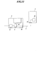
- FIG. 11 is a diagram schematically showing a state in which the cable 5 is connected to the radiation image detection apparatus 2.
- the connection detection section 90 detects that fact.
- the detection result by the connection detection unit 90 is output to the charging current setting unit 91 of the charging control circuit 9.
- the charging current setting unit 91 sets the current value of the charging current to a small value such as 0.1 ampere so as to charge the battery 28 with a small current. Set to current.
- a setting result by the charging current setting unit 91 is output to the switch control unit 92.
- the switch control unit 92 outputs the detection result of the voltage of the battery 28 from the battery voltage detection unit 96, and outputs the current value of the charging current flowing into the battery 28 from the charging current detection unit 95.
- the switch control unit 92 determines whether or not the battery 28 needs to be charged based on the results output from the battery voltage detection unit 96 and the charging current detection unit 95.
- the charging switch 93 is controlled so that charging is performed at the current value (for example, 0.1 ampere) set in the setting unit 91. Thereby, constant current charging at a current value of 0.1 ampere is started.
- imaging and data processing can be performed in parallel with the charging of the battery 28, and the radiation image detection device 2 can be connected to the radiation image detection device 2 from the battery 28 or from the external power source via the detection device side connector 26.
- Electric power is supplied to each functional unit. Note that, when photographing or the like is performed while charging, the supplied current value increases as power is supplied to each functional unit in parallel.
- the battery voltage detection unit 96 and the charging current detection unit 95 output detection results to the switch control unit 92 as needed, and the switch control unit 92 performs constant current charging and constant voltage based on the detection results. It is always determined whether to charge, whether to continue or end charging.
- the switch control unit 92 When the voltage of the battery 28 output from the battery voltage detection unit 96 becomes equal to or higher than a predetermined value, the switch control unit 92 performs switching control of the charging switch 93 so as to switch from constant current charging to constant voltage charging. Further, when the current value output from the charging current detection unit 95 becomes equal to or less than a predetermined value, the switch control unit 92 determines that the charging should be terminated, and performs control for switching the charging switch 93 to OFF. Thereby, charging of the battery 28 is completed.
- the cradle output connector portion 42 when the cradle output connector portion 42 is connected to the detection device side connector portion 26, high-speed charging can be performed with a large current, and the cable 5 is connected. Can perform processing such as photographing while charging with a small current.
- the charging current is reduced, so that the current capacity of the cable 5 can be reduced and the cable 5 can be thinned. Thereby, the handling property of the radiation image detection apparatus 2 is improved, and it is possible to easily perform imaging or the like without charging the battery 28 while charging the battery 28.
- the current flowing through the cable 5 is reduced, the power loss corresponding to the voltage drop caused by the cable 5 can be reduced.
- the charge control circuit 9 is provided in the cradle 4 in the cradle 4 is taken as an example, but the charge control circuit 9 is not limited to the case where the charge control circuit 9 is provided in the cradle 4.
- an external device such as the wireless access point 113 in the photographing room R1 (see FIG. 5) is configured to receive power from an external power source and connect the cradle 4 and the cable 5, and charge control is performed in the external device.
- a circuit may be provided to perform charging control or the like when charging the battery 28.
Landscapes
- Health & Medical Sciences (AREA)
- Life Sciences & Earth Sciences (AREA)
- Engineering & Computer Science (AREA)
- Medical Informatics (AREA)
- Physics & Mathematics (AREA)
- Pathology (AREA)
- Molecular Biology (AREA)
- Biophysics (AREA)
- High Energy & Nuclear Physics (AREA)
- Veterinary Medicine (AREA)
- Nuclear Medicine, Radiotherapy & Molecular Imaging (AREA)
- Optics & Photonics (AREA)
- Public Health (AREA)
- Radiology & Medical Imaging (AREA)
- Biomedical Technology (AREA)
- Heart & Thoracic Surgery (AREA)
- General Health & Medical Sciences (AREA)
- Surgery (AREA)
- Animal Behavior & Ethology (AREA)
- Computer Networks & Wireless Communication (AREA)
- Multimedia (AREA)
- Signal Processing (AREA)
- Mathematical Physics (AREA)
- Apparatus For Radiation Diagnosis (AREA)
- Measurement Of Radiation (AREA)
- Radiography Using Non-Light Waves (AREA)
Abstract
Description
そこで、放射線画像検出装置に外部から電力を供給するケーブルを接続して、充電を行いながら撮影等を行う構成とすることも考えられる。
また、大電流で充電を行う場合には、ケーブルによる電力損失が大きく、充電制御回路等における発熱が大きくなるため、この熱が放射線画像検出装置のセンサパネル部の特性に影響を与えてしまう。さらに、充電制御回路を流れる電流が大きくなるため、これに比例して充電制御回路から発生するノイズも大きくなる。
このため、充電を行いながらこれと同時並行的に撮影等を行おうとした場合には、画像信号に悪影響を与え、画質が劣化する等、不具合が生じるおそれもある。
各機能部に電力を供給するバッテリを内蔵し、前記バッテリからの電力供給による駆動が可能なカセッテ型の放射線画像検出装置と、
前記バッテリの充電制御を行う充電制御回路と、
前記放射線画像検出装置を載置することにより、外部から前記放射線画像検出装置に電力を供給可能に構成されたクレードルと、
前記放射線画像検出装置と接続することにより、外部から前記放射線画像検出装置に電力を供給可能なケーブルと、を備え、
前記放射線画像検出装置は、前記クレードル及び前記ケーブルのそれぞれと電気的に接続可能に構成され受電を行う接続部を有し、
前記バッテリの充電は、前記クレードルによる接続と前記ケーブルによる接続との双方により可能に構成され、
前記充電制御回路は、前記クレードルによる接続時と、前記ケーブルによる接続時とで充電電流を切り替えることを特徴とする。
また、ケーブル、及び充電制御回路を流れる電流を小さくすることができるため、ケーブルによる電圧降下分の電力ロスを低減させることができ、充電制御回路における発熱が小さくなるとともに、充電制御回路からのノイズの発生量を抑えることができる。これにより、熱やノイズの影響による画質の劣化を抑制することができる。
さらに、クレードルに接続したときは大電流で充電することができ、短時間での充電が可能となるとの効果を奏する。
まず、図1から図7を参照しつつ、本発明に係る放射線画像検出システムの第1の実施形態について説明する。ただし、本発明を適用可能な実施形態は図示例のものに限定されるものではない。
本実施形態においてクレードル4には、出力コネクタ部として、放射線画像検出装置2がクレードルに載置されたときに検出装置側コネクタ部26と接続されるクレードル出力コネクタ部42と、検出装置側コネクタ部26に接続されるケーブル5が接続されるケーブル用出力コネクタ部43とが設けられている。
また、ケーブル用出力コネクタ部43に接続されたケーブル5が検出装置側コネクタ部26に接続されるとケーブル5を介してAC/DC定電圧電源41から放射線画像検出装置2に電力が供給される。
なお、本実施形態では、ケーブル5がクレードル4を介して外部電源と接続される例を示しているが、ケーブル5と外部電源との接続の仕方はこれに限定されず、ケーブル5がクレードル4の外にあるAC/DC定電圧電源と直接接続されて外部電源から放射線画像検出装置2への電力供給が行われるように構成してもよい。
ケーブル5の径が細い場合には、供給可能な電流容量は小さくなるが、その分ケーブル5における電圧降下分の電力ロスを低減させることができる。また、供給可能な電流容量は小さければその分、後述する充電制御回路6における発熱が小さくなり、熱の影響による画質劣化を抑制することができる。また、充電制御回路6から生じるノイズの発生量を抑えることも可能となる。
なお、以下では、放射線画像検出装置2として、シンチレータ等を備え、放射された放射線を可視光等の他の波長の電磁波に変換して電気信号を得るいわゆる間接型の放射線画像検出装置について説明するが、本発明は、シンチレータ等を介さずに放射線を放射線検出素子で直接検出する、いわゆる直接型の放射線画像検出装置に対しても適用することができる。
放射線画像検出装置2は、図2に示すように、内部を保護する筐体21を備えている。筐体21は、少なくとも放射線の照射を受ける側の面X(以下、放射線入射面Xという。)が、放射線を透過するカーボン板やプラスチック等の材料で形成されている。なお、図2では、筐体21がフロント部材21aとバック部材21bとで形成されている場合が示されているが、その形状、構成は特に限定されず、この他にも、筐体21を筒状のいわゆるモノコック状に形成することも可能である。
バッテリ28は、充電可能なものであり、例えばニッカド電池、ニッケル水素電池、リチウムイオン電池、小型シール鉛電池、鉛蓄電池等の充電自在な二次電池や、電気二重層コンデンサ、リチウムイオンキャパシタ(LIC)等の蓄電素子等を適用することができる。
このうち、特に、リチウムイオンキャパシタは、蓄電効率に優れるとともに、大電流(例えば5~10アンペア)による高速充電が可能であり、充電時間を大幅に短縮することができるため、好ましい。
後述するように、検出装置側コネクタ部26にクレードル4のクレードル出力コネクタ部42が接続されるとバッテリ28に大電流を供給して急速充電することが可能となる。また、検出装置側コネクタ部26にケーブル5が接続されると、外部から供給される電力で各機能部を駆動させつつバッテリ28の充電を行うことも可能となるように構成されている。
なお、本実施形態において、接続検出部60が、検出装置側コネクタ部26に接続されたのがクレードル4であるかケーブル5であるかを検出する手法は特に限定されない。例えば、検出装置側コネクタ部26に機械的なスイッチ(図示せず)を設けて、クレードル4が接続されたときとケーブル5が接続されたときとでスイッチのON/OFF状態が切り変わるように構成してもよいし、検出用の接点を設けて、クレードル4が接続されたときとケーブル5が接続されたときとで接点の短絡/開放状態が変わるように構成してもよい。
図3に示すように、センサパネル部24の各光電変換素子23の一方の電極にはそれぞれ信号読出し用のスイッチ素子であるTFT46のソース電極が接続されている。また、各光電変換素子23の他方の電極にはバイアス線Lbが接続されており、バイアス線Lbはバイアス電源36に接続されていて、バイアス電源36から各光電変換素子23に逆バイアス電圧が印加されるようになっている。
信号処理部34は、画像データに所定の信号処理を施すことによって画像データを外部に出力するのに適した形式のデータとする機能部である。
制御部30は、ROMに格納された所定のプログラムを読み出してRAMの作業領域に展開し、当該プログラムに従ってCPUが各種処理を実行するようになっている。
なお、記憶部31は内蔵型のメモリでもよいし、メモリカード等の着脱可能なメモリでもよい。また、その容量は特に限定されないが、複数枚分の画像データを保存可能な容量を有することが好ましい。このような記憶手段を備えることによって、被写体に対して連続して放射線を照射し、その度ごとに画像データを記録し蓄積していくことができ、連続撮影や動画撮影を行うことが可能となる。
本実施形態において、通信部35は、読取部45によって読み取られA/D変換部40においてアナログ信号からデジタル信号に変換された画像信号に基づく画像データを外部機器であるコンソール101に送信するとともにコンソール101等から撮影オーダ情報等を受信する。
図4に示すように、本実施形態において、充電制御回路6は、充電電流設定部61、スイッチ制御部62、充電スイッチ63、インダクタ64、充電電流検出部65、バッテリ電圧検出部66を備えている。
本実施形態において、検出装置側コネクタ部26にクレードル出力コネクタ部42が接続されたと検知された場合には、バッテリ28に供給する充電電流の電流値を高く設定して、大電流による高速充電を行うようになっている。
また、検出装置側コネクタ部26にケーブル5が接続されたと検知された場合には、バッテリ28に供給する電流の電流値を低く設定して、小電流による充電を行うようにする。そして、この場合には、バッテリ28の充電を行いながら、これと並行して撮影等を行うことができるようになっており、ケーブル5を介して外部電源から供給された電力がバッテリ28のほか、電源回路29を介して各機能部にも供給されるようになっている。
後述のように、本実施形態では、バッテリ28の充電の際、ある程度まで定電流充電を行ったら定電圧充電に切り替えるようになっているが、充電方式が定電流充電から定電圧充電に切り替わると、時間の経過に伴って徐々にバッテリ28に流れる電流が減少していく。充電電流検出部65は、この電流値の変化を検出して、スイッチ制御部62に出力する。
本実施形態では、バッテリ28を充電する際、まずバッテリ28に所定の電流値の電流を供給して充電を行う定電流充電を行う。定電流充電が開始されると、時間の経過に伴い、バッテリ28の電圧が徐々に上がっていく。すなわち、一定の電流値を維持するために電圧を徐々に上げながら充電が行われる。しかし、バッテリ28の電圧が所定の電圧を超えた場合に、そのまま定電流充電を続けると電流が流れすぎて容量オーバーとなってしまう。このため、バッテリ28の電圧が所定の閾値に達するまでは定電流充電を行うが、バッテリ28の電圧が所定の閾値に達すると、充電方式を定電圧充電に切り替えるようになっている。そして、定電圧充電により容量ぎりぎりまでバッテリ28の充電を行い、フルに充電された時点で充電を中止させる。
充電スイッチ63は、スイッチ制御部62の制御により、このような切り替えを行う機能部である。
なお、充電スイッチ63の種類としては、一般にFETが用いられるが、電磁式スイッチ(電磁式リレー)でも半導体スイッチ(SSR)や光電スイッチ(Photoリレー)等のいずれで構成してもよい。
また、定電圧充電を行ってバッテリ28がフルに充電された状態になると、スイッチ制御部62は充電スイッチ63をOFFとし、バッテリ28の充電を中止するように制御するようになっている。具体的には、スイッチ制御部62には、前述のように、充電電流検出部65から検出結果が出力されるようになっており、スイッチ制御部62は、この充電電流検出部65からの検出結果に基づいて、電流がほとんど流れなくなった時点(所定の閾値以下となった時点)で充電終了と判断し、充電スイッチ63をOFFとするようになっている。
なお、本実施形態においては、放射線画像撮影システム内に1つの撮影室R1が設けられており、撮影室R1内に3つの放射線画像検出装置2が配置されている場合を例として説明するが、撮影室の数、各撮影室に設けられる放射線画像検出装置2の数は図示例に限定されない。
また、撮影室R1が複数ある場合に、コンソール101は各撮影室R1に対応して設けられていなくてもよく、複数の撮影室R1に対して1台のコンソール101が対応付けられていてもよい。
なお、図5には撮影室R1内に臥位撮影用のブッキー装置110aと立位撮影用のブッキー装置110bとがそれぞれ1つずつ設けられている場合を例示しているが、撮影室R1内に設けられるブッキー装置110の数は特に限定されない。また、本実施形態では、各ブッキー装置110に対応して1つずつ放射線発生装置112が設けられている構成を例示しているが、例えば、撮影室R1内に放射線発生装置112を1つ備え、複数のブッキー装置110に対して1つの放射線発生装置112が対応し、適宜位置を移動させたり、放射線照射方向を変更する等して使用するようになっていてもよい。
コンソール101は、放射線画像検出装置2から送られた画像データに基づく画像を表示部に表示させたり、この画像データに各種の画像処理を施すものである。
本実施形態において、コンソール101は、ネットワークNを介して、HIS/RIS121、PACSサーバ122、イメージャ123等の外部装置と接続されるようになっている。
放射線画像検出装置2をクレードル4に装着すると、検出装置側コネクタ部26にクレードル出力コネクタ部42が接続されたことが接続検出部60によって検出される。接続検出部60による検出結果は、放射線画像検出装置2内に設けられた充電制御回路6の充電電流設定部61に出力される。
充電電流設定部61は、接続検出部60から検出結果が送られると、これに応じて、バッテリ28を大電流で充電するように、バッテリ28に供給する充電電流の電流値を、例えば2アンペア等の大電流に設定する。充電電流設定部61による設定結果はスイッチ制御部62に出力される。スイッチ制御部62には、バッテリ電圧検出部66からバッテリ28の電圧の検出結果が出力され、充電電流検出部65からバッテリ28に流れ込む充電電流の電流値が出力される。スイッチ制御部62は、これらバッテリ電圧検出部66及び充電電流検出部65から出力された結果に基づいてバッテリ28の充電の必要があるかを判断し、充電の必要がある場合には充電スイッチをONとするとともに、充電電流設定部61において設定された電流値(例えば2アンペア)で充電を行うように充電スイッチ63を制御する。これにより、一定の電流値(例えば設定された電流値である2アンペア)での定電流充電が開始される。
充電中、バッテリ電圧検出部66及び充電電流検出部65からは、随時スイッチ制御部62に検出結果が出力されており、スイッチ制御部62は、この検出結果に基づいて、定電流充電、定電圧充電のいずれを行うべきか、充電を続行すべきか終了すべきかを常に判断する。そして、バッテリ電圧検出部66から出力されるバッテリ28の電圧が所定の値以上となると、スイッチ制御部62は、定電流充電から定電圧充電に切り替えるように充電スイッチ63の制御を行う。
また、充電電流検出部65から出力される電流値が所定値以下になると、スイッチ制御部62は充電を終了するべきと判断し、充電スイッチ63をOFFに切り替える制御を行う。これにより、バッテリ28の充電が終了する。
クレードル4のケーブル用出力コネクタ部43に接続されたケーブル5が放射線画像検出装置2の検出装置側コネクタ部26に接続されると、その旨が接続検出部60によって検出される。接続検出部60による検出結果は、充電制御回路6の充電電流設定部61に出力される。
充電電流設定部61は、接続検出部60から検出結果が送られると、これに応じて、バッテリ28を小電流で充電するように、充電電流の電流値を、例えば0.1アンペア等の小電流に設定する。充電電流設定部61による設定結果はスイッチ制御部62に出力される。スイッチ制御部62には、バッテリ電圧検出部66からバッテリ28の電圧の検出結果が出力され、充電電流検出部65からバッテリ28に流れ込む充電電流の電流値が出力される。スイッチ制御部62は、これらバッテリ電圧検出部66及び充電電流検出部65から出力された結果に基づいてバッテリ28の充電の必要があるかを判断し、充電の必要がある場合には、充電電流設定部61において設定された電流値(例えば0.1アンペア)で充電を行うように充電スイッチ63を制御する。これにより、0.1アンペアの電流値での定電流充電が開始される。
また、この場合には、バッテリ28の充電と並行して撮影やデータ処理等が可能となっており、バッテリ28から、又は検出装置側コネクタ部26を介して外部電源から放射線画像検出装置2の各機能部に電力が供給されるようになっている。なお、充電しながら撮影等を行っている場合、各機能部にも並行して電力が供給される分、供給される電流値は大きくなる。
充電中、バッテリ電圧検出部66及び充電電流検出部65からは、随時スイッチ制御部62に検出結果が出力されており、スイッチ制御部62は、この検出結果に基づいて、定電流充電、定電圧充電のいずれを行うべきか、充電を続行すべきか終了すべきかを常に判断する。そして、バッテリ電圧検出部66から出力されるバッテリ28の電圧が所定の値以上となると、スイッチ制御部62は、定電流充電から定電圧充電に切り替えるように充電スイッチ63の制御を行う。
また、充電電流検出部65から出力される電流値が所定値以下になると、スイッチ制御部62は充電を終了するべきと判断し、充電スイッチ63をOFFに切り替える制御を行う。これにより、バッテリ28充電が終了する。
そして、ケーブル5が接続された場合には、充電電流を小さくするため、ケーブル5の電流容量を小さくすることができ、ケーブル5の細線化が可能となる。これにより、放射線画像検出装置2のとり廻し性が向上し、バッテリ28の充電を行いながら、バッテリ28の残量を気にせずに、容易に撮影等を行うことができる。
また、ケーブル5に流れる電流を小さくすることから、ケーブル5による電圧降下分の電力ロスを低減することができる。
また、ケーブル5が接続された場合には、小電流による充電を行うため、充電制御回路6における発熱が小さくなり、熱の影響による画質劣化を抑制することができる。また、充電制御回路6からのノイズの発生量を抑えることができるため、充電による画質への影響を抑えることができる。
また、検出装置側コネクタ部26にクレードル出力コネクタ部42が接続された場合には、その状態で撮影が行われることは想定できないため、充電による発熱やノイズの発生による影響を気にする必要がない。そこで、このような状態のときには大電流で充電することにより、短時間での充電が可能となる。
例えば、図8に示すように、クレードル4に、クレードル4への装着による接続、ケーブル5による接続いずれにも兼用の出力コネクタ部44を1つ設ける構成としてもよい。
例えば、検出装置側コネクタ部26にケーブル5が接続された場合であって、現に撮影や画像データの送信等の処理が行われているときにはバッテリ28の充電を行わないようにする等、放射線画像検出装置2の各機能部の稼動状態に応じて、外部電源から受電した電力のバッテリ28に対する供給を制御するように構成してもよい。
この場合、さらに、電力供給用のコネクタ部(検出装置側コネクタ部26、クレードル出力コネクタ部42及びケーブル用出力コネクタ部43)が通信用のコネクタ部を兼用する構成としてもよい。
次に、図9から図11を参照しつつ、本発明の第2の実施形態について説明する。なお、第2の実施形態は、バッテリの充電を制御する充電制御回路の構成が第1の実施形態と異なるものであるため、以下においては、特に第1の実施形態と異なる点について説明する。
充電電流設定部91は、接続検出部90の検知結果に基づいてバッテリ28の充電を行う際にバッテリ28に供給する電流の電流値を設定する。
また、バッテリ電圧検出部96で検出されたバッテリ28の電圧及び充電電流検出部95で検出された充電電流の電流値はスイッチ制御部92に出力され、スイッチ制御部92は、これらの検出結果に基づいて、充電スイッチ93の制御を行う。スイッチ制御部92により充電スイッチ93が制御されることにより、クレードル接続による充電かケーブル接続による充電かの別や、バッテリ28の仕様、充電状態等に応じた電流値の電流が検出装置側コネクタ部26を介してバッテリ28に供給される。
放射線画像検出装置2をクレードル4に装着すると、検出装置側コネクタ部26にクレードル出力コネクタ部42が接続されたことが接続検出部90によって検出される。接続検出部90による検出結果は、クレードル4に設けられた充電制御回路9の充電電流設定部91に出力される。
充電電流設定部91は、接続検出部90から検出結果が送られると、これに応じて、バッテリ28を大電流で充電するように、充電電流の電流値を、例えば2アンペア等の大電流に設定する。充電電流設定部91による設定結果はスイッチ制御部92に出力される。スイッチ制御部92には、バッテリ電圧検出部96からバッテリ28の電圧の検出結果が出力され、充電電流検出部95からバッテリ28に流れ込む充電電流の電流値が出力される。スイッチ制御部92は、これらバッテリ電圧検出部96及び充電電流検出部95から出力された結果に基づいてバッテリ28の充電の必要があるかを判断し、充電の必要がある場合には、充電電流設定部91において設定された電流値(例えば2アンペア)で充電を行うように充電スイッチ93を制御する。これにより、2アンペアの電流値での定電流充電が開始される。
充電中、バッテリ電圧検出部96及び充電電流検出部95からは、随時スイッチ制御部92に検出結果が出力され、スイッチ制御部92は、この検出結果に基づいて、定電流充電、定電圧充電のいずれを行うべきか、充電を続行すべきか終了すべきかを常に判断する。そして、バッテリ電圧検出部96から出力されるバッテリ28の電圧が所定の値以上となると、スイッチ制御部92は、定電流充電から定電圧充電に切り替えるように充電スイッチ93の制御を行う。
また、充電電流検出部95から出力される電流値が所定値以下になると、スイッチ制御部92は充電を終了するべきと判断し、充電スイッチ93をOFFに切り替える制御を行う。これにより、バッテリ28の充電が終了する。
クレードル4のケーブル用出力コネクタ部43に接続されたケーブル5が放射線画像検出装置2の検出装置側コネクタ部26に接続されると、その旨が接続検出部90によって検出される。接続検出部90による検出結果は、充電制御回路9の充電電流設定部91に出力される。
充電電流設定部91は、接続検出部90から検出結果が送られると、これに応じて、バッテリ28を小電流で充電するように、充電電流の電流値を、例えば0.1アンペア等の小電流に設定する。充電電流設定部91による設定結果はスイッチ制御部92に出力される。スイッチ制御部92には、バッテリ電圧検出部96からバッテリ28の電圧の検出結果が出力され、充電電流検出部95からバッテリ28に流れ込む充電電流の電流値が出力される。スイッチ制御部92は、これらバッテリ電圧検出部96及び充電電流検出部95から出力された結果に基づいてバッテリ28の充電の必要があるかを判断し、充電の必要がある場合には、充電電流設定部91において設定された電流値(例えば0.1アンペア)で充電を行うように充電スイッチ93を制御する。これにより、0.1アンペアの電流値での定電流充電が開始される。
また、この場合には、バッテリ28の充電と並行して撮影やデータ処理等が可能となっており、バッテリ28から、又は検出装置側コネクタ部26を介して外部電源から放射線画像検出装置2の各機能部に電力が供給されるようになっている。なお、充電しながら撮影等を行っている場合、各機能部にも並行して電力が供給される分、供給される電流値は大きくなる。
充電中、バッテリ電圧検出部96及び充電電流検出部95からは、随時スイッチ制御部92に検出結果が出力されており、スイッチ制御部92は、この検出結果に基づいて、定電流充電、定電圧充電のいずれを行うべきか、充電を続行すべきか終了すべきかを常に判断する。そして、バッテリ電圧検出部96から出力されるバッテリ28の電圧が所定の値以上となると、スイッチ制御部92は、定電流充電から定電圧充電に切り替えるように充電スイッチ93の切り替え制御を行う。
また、充電電流検出部95から出力される電流値が所定値以下になると、スイッチ制御部92は充電を終了するべきと判断し、充電スイッチ93をOFFに切り替える制御を行う。これにより、バッテリ28の充電が終了する。
そして、ケーブル5が接続された場合には、充電電流を小さくするため、ケーブル5の電流容量を小さくすることができ、ケーブル5の細線化が可能となる。これにより、放射線画像検出装置2のとり廻し性が向上し、バッテリ28の充電を行いながら、バッテリ28の残量を気にせずに、容易に撮影等を行うことができる。
また、また、ケーブル5に流れる電流を小さくすることから、ケーブル5による電圧降下分の電力ロスを低減することができる。
また、ケーブル5が接続された場合には、小電流による充電を行うため、充電制御回路9からのノイズの発生量を抑えることができるため、充電による画質への影響を抑えることができる。
また、本実施形態では、充電制御回路9が放射線画像検出装置2内ではなく、クレードル4内に設けられているため、放射線画像検出装置2が充電制御回路9で発生する熱の影響を受け難く、熱による画質劣化を防止することができる。
また、クレードル出力コネクタ部42が接続された場合には、その状態で撮影が行われることは想定できないため、充電によるノイズの発生等による影響を気にする必要がない。そこで、このような状態のときには大電流で充電することにより、短時間での充電が可能となり、便宜である。
例えば、撮影室R1(図5参照)内の無線アクセスポイント113等の外部装置を、外部電源から電力を受電するとともに、クレードル4及びケーブル5を接続可能に構成し、この外部装置内に充電制御回路を設けて、バッテリ28を充電する際の充電制御等を行うようにしてもよい。
2 放射線画像撮影装置
4 クレードル
5 ケーブル
6 充電制御回路
8 コンセント
24 センサパネル部
25 インジケータ
26 検出装置側コネクタ部
28 バッテリ
29 電源回路
30 制御部
41 AC/DC定電圧電源
42 クレードル出力コネクタ部
43 ケーブル用出力コネクタ部
60 接続検出部
61 充電電流設定部
62 スイッチ制御部
63 充電スイッチ
64 インダクタ
65 充電電流検出部
66 バッテリ電圧検出部
67 バッテリスイッチ
100 放射線画像撮影システム
Claims (5)
- 各機能部に電力を供給するバッテリを内蔵し、前記バッテリからの電力供給による駆動が可能なカセッテ型の放射線画像検出装置と、
前記バッテリの充電制御を行う充電制御回路と、
前記放射線画像検出装置を載置することにより、外部から前記放射線画像検出装置に電力を供給可能に構成されたクレードルと、
前記放射線画像検出装置と接続することにより、外部から前記放射線画像検出装置に電力を供給可能なケーブルと、を備え、
前記放射線画像検出装置は、前記クレードル及び前記ケーブルのそれぞれと電気的に接続可能に構成され受電を行う接続部を有し、
前記バッテリの充電は、前記クレードルによる接続と前記ケーブルによる接続との双方により可能に構成され、
前記充電制御回路は、前記クレードルによる接続時と、前記ケーブルによる接続時とで充電電流を切り替えることを特徴とする放射線画像検出システム。 - 前記充電制御回路は、前記クレードルの内部に設けられていることを特徴とする請求項1に記載の放射線画像検出システム。
- 前記接続部に前記クレードル又は前記ケーブルのいずれが接続されているかを検知する検知手段を有し、
前記充電制御回路は、前記検知手段の検知結果に応じて充電電流を切り替えることを特徴とする請求項1又は請求項2に記載の放射線画像検出システム。 - 前記放射線画像検出装置は、電力を前記バッテリのみから取得して駆動するバッテリ駆動状態と、電力を前記クレードル又は前記ケーブルを介して、外部から給電して駆動する外部給電駆動状態との2つの駆動状態が選択可能であり、
前記外部給電駆動状態のときに、前記バッテリの充電を並行して行うことを特徴とする請求項1から請求項3のいずれか一項に記載の放射線画像検出システム。 - 前記バッテリは、リチウムイオンキャパシタであることを特徴とする請求項1から請求項4のいずれか一項に記載の放射線画像検出システム。
Priority Applications (4)
| Application Number | Priority Date | Filing Date | Title |
|---|---|---|---|
| EP10755785.2A EP2412312B1 (en) | 2009-03-24 | 2010-02-18 | Radiation image detecting system |
| JP2011505931A JP5609863B2 (ja) | 2009-03-24 | 2010-02-18 | 放射線画像検出システム |
| CN201080013103.1A CN102361591B (zh) | 2009-03-24 | 2010-02-18 | 放射线图像检测系统 |
| US13/255,929 US8399846B2 (en) | 2009-03-24 | 2010-02-18 | Radiation image detecting system |
Applications Claiming Priority (2)
| Application Number | Priority Date | Filing Date | Title |
|---|---|---|---|
| JP2009-071405 | 2009-03-24 | ||
| JP2009071405 | 2009-03-24 |
Publications (1)
| Publication Number | Publication Date |
|---|---|
| WO2010109984A1 true WO2010109984A1 (ja) | 2010-09-30 |
Family
ID=42780680
Family Applications (1)
| Application Number | Title | Priority Date | Filing Date |
|---|---|---|---|
| PCT/JP2010/052400 Ceased WO2010109984A1 (ja) | 2009-03-24 | 2010-02-18 | 放射線画像検出システム |
Country Status (5)
| Country | Link |
|---|---|
| US (1) | US8399846B2 (ja) |
| EP (1) | EP2412312B1 (ja) |
| JP (1) | JP5609863B2 (ja) |
| CN (1) | CN102361591B (ja) |
| WO (1) | WO2010109984A1 (ja) |
Cited By (6)
| Publication number | Priority date | Publication date | Assignee | Title |
|---|---|---|---|---|
| JP2010223863A (ja) * | 2009-03-25 | 2010-10-07 | Fujifilm Corp | 放射線検出装置、放射線画像撮影システム及び放射線画像撮影方法 |
| JP2012110167A (ja) * | 2010-11-19 | 2012-06-07 | Konica Minolta Medical & Graphic Inc | 充電システム |
| JP2012161561A (ja) * | 2011-02-09 | 2012-08-30 | Fujifilm Corp | 超音波診断装置 |
| CN103126699A (zh) * | 2011-11-30 | 2013-06-05 | 通用电气公司 | 便携式辐射检测器及系统 |
| US8876721B2 (en) | 2011-02-01 | 2014-11-04 | Fujifilm Corporation | Ultrasound diagnostic apparatus |
| JP2015167449A (ja) * | 2014-03-04 | 2015-09-24 | コニカミノルタ株式会社 | 電子機器 |
Families Citing this family (12)
| Publication number | Priority date | Publication date | Assignee | Title |
|---|---|---|---|---|
| JP6032900B2 (ja) * | 2012-02-06 | 2016-11-30 | キヤノン株式会社 | 電子機器 |
| US8809996B2 (en) | 2012-06-29 | 2014-08-19 | Taiwan Semiconductor Manufacturing Company, Ltd. | Package with passive devices and method of forming the same |
| CN103162839B (zh) * | 2013-03-25 | 2014-10-22 | 南京大学 | 用于Nb5N6常温太赫兹检测器线阵的读出电路 |
| KR102400997B1 (ko) * | 2014-09-15 | 2022-05-23 | 삼성전자주식회사 | 초음파 프로브 및 그 작동 방법과 거치대 |
| JP6251147B2 (ja) * | 2014-09-29 | 2017-12-20 | 富士フイルム株式会社 | 電子カセッテおよび電子カセッテの作動方法 |
| US10368823B2 (en) * | 2015-01-30 | 2019-08-06 | Canon Kabushiki Kaisha | Radiographing apparatus, control apparatus, control method, and storage medium |
| CN106816914A (zh) * | 2015-12-01 | 2017-06-09 | 长沙市百氏特医疗器械有限公司 | 一种用于无线平板探测器的自动充电装置 |
| WO2017187579A1 (ja) * | 2016-04-27 | 2017-11-02 | 株式会社島津製作所 | X線装置 |
| CN106725558A (zh) * | 2017-02-07 | 2017-05-31 | 奕瑞影像科技(太仓)有限公司 | 一种平板探测器系统及其供电方法 |
| JP6971613B2 (ja) * | 2017-04-19 | 2021-11-24 | キヤノン株式会社 | 放射線撮影装置、放射線撮影システム、放射線撮影方法、及びプログラム |
| JP7087435B2 (ja) * | 2018-02-19 | 2022-06-21 | コニカミノルタ株式会社 | 放射線画像撮影装置及び放射線画像撮影システム |
| CN111886852B (zh) * | 2019-02-15 | 2022-04-12 | 松下知识产权经营株式会社 | 摄像装置 |
Citations (5)
| Publication number | Priority date | Publication date | Assignee | Title |
|---|---|---|---|---|
| JPH06342099A (ja) | 1992-12-23 | 1994-12-13 | E I Du Pont De Nemours & Co | X線像記録用電子カセットおよびx線ラジオグラム撮影方法 |
| JP3302163B2 (ja) | 1994-03-11 | 2002-07-15 | 株式会社東芝 | X線撮像装置及びx線診断装置 |
| JP2007167649A (ja) * | 2005-12-19 | 2007-07-05 | General Electric Co <Ge> | 携帯型イメージングのためのシステム、装置及び方法 |
| JP2008043038A (ja) * | 2006-08-04 | 2008-02-21 | Matsushita Electric Ind Co Ltd | 携帯端末機 |
| JP2009053670A (ja) * | 2007-07-27 | 2009-03-12 | Fujifilm Corp | 放射線検出カセッテ及び放射線画像撮影システム |
Family Cites Families (15)
| Publication number | Priority date | Publication date | Assignee | Title |
|---|---|---|---|---|
| US5877501A (en) * | 1996-11-26 | 1999-03-02 | Picker International, Inc. | Digital panel for x-ray image acquisition |
| JP2000347330A (ja) * | 1999-06-01 | 2000-12-15 | Konica Corp | カセッテ型放射線画像読取装置 |
| JP2001224579A (ja) | 2000-02-15 | 2001-08-21 | Hitachi Medical Corp | X線撮影装置 |
| JP4164282B2 (ja) * | 2002-04-16 | 2008-10-15 | キヤノン株式会社 | 放射線撮影装置、放射線撮影方法及びコンピュータプログラム |
| JP2004173907A (ja) * | 2002-11-27 | 2004-06-24 | Canon Inc | X線撮像装置 |
| JP2005102854A (ja) * | 2003-09-29 | 2005-04-21 | Konica Minolta Medical & Graphic Inc | 放射線画像検出器、放射線画像撮影装置及び放射線画像診断システム |
| JP4581713B2 (ja) * | 2005-01-31 | 2010-11-17 | コニカミノルタエムジー株式会社 | 放射線画像撮影システム |
| JPWO2006080377A1 (ja) * | 2005-01-31 | 2008-06-19 | コニカミノルタエムジー株式会社 | 放射線画像検出器及び放射線画像撮影システム |
| US20060172801A1 (en) * | 2005-01-31 | 2006-08-03 | Saied Hussaini | Video game controller with rechargeable battery system |
| JP2008134057A (ja) * | 2005-03-10 | 2008-06-12 | Konica Minolta Medical & Graphic Inc | 放射線画像検出器及び放射線画像撮影システム |
| ATE387653T1 (de) * | 2005-10-13 | 2008-03-15 | Research In Motion Ltd | Vorrichtung und verfahren zur unterstützung der usb-aufzählung eines bus-betriebenen tragbaren geräts |
| JP5300216B2 (ja) * | 2006-08-29 | 2013-09-25 | キヤノン株式会社 | 電子カセッテ型放射線検出装置 |
| JP4940919B2 (ja) * | 2006-12-06 | 2012-05-30 | コニカミノルタエムジー株式会社 | 放射線画像撮影システム |
| US7829859B2 (en) | 2007-07-27 | 2010-11-09 | Fujifilm Corporation | Radiation detecting cassette and radiation image capturing system |
| JP2009181001A (ja) * | 2008-01-31 | 2009-08-13 | Fujifilm Corp | 放射線変換器 |
-
2010
- 2010-02-18 CN CN201080013103.1A patent/CN102361591B/zh active Active
- 2010-02-18 WO PCT/JP2010/052400 patent/WO2010109984A1/ja not_active Ceased
- 2010-02-18 EP EP10755785.2A patent/EP2412312B1/en active Active
- 2010-02-18 JP JP2011505931A patent/JP5609863B2/ja active Active
- 2010-02-18 US US13/255,929 patent/US8399846B2/en active Active
Patent Citations (5)
| Publication number | Priority date | Publication date | Assignee | Title |
|---|---|---|---|---|
| JPH06342099A (ja) | 1992-12-23 | 1994-12-13 | E I Du Pont De Nemours & Co | X線像記録用電子カセットおよびx線ラジオグラム撮影方法 |
| JP3302163B2 (ja) | 1994-03-11 | 2002-07-15 | 株式会社東芝 | X線撮像装置及びx線診断装置 |
| JP2007167649A (ja) * | 2005-12-19 | 2007-07-05 | General Electric Co <Ge> | 携帯型イメージングのためのシステム、装置及び方法 |
| JP2008043038A (ja) * | 2006-08-04 | 2008-02-21 | Matsushita Electric Ind Co Ltd | 携帯端末機 |
| JP2009053670A (ja) * | 2007-07-27 | 2009-03-12 | Fujifilm Corp | 放射線検出カセッテ及び放射線画像撮影システム |
Non-Patent Citations (2)
| Title |
|---|
| KATSUHIKO NAOI: "Recent advances in electrochemical supercapacitors", KAGAKU KOGYO, vol. 59, no. 10, 1 October 2008 (2008-10-01), pages 770 - 775 * |
| See also references of EP2412312A4 |
Cited By (8)
| Publication number | Priority date | Publication date | Assignee | Title |
|---|---|---|---|---|
| JP2010223863A (ja) * | 2009-03-25 | 2010-10-07 | Fujifilm Corp | 放射線検出装置、放射線画像撮影システム及び放射線画像撮影方法 |
| JP2012110167A (ja) * | 2010-11-19 | 2012-06-07 | Konica Minolta Medical & Graphic Inc | 充電システム |
| US8876721B2 (en) | 2011-02-01 | 2014-11-04 | Fujifilm Corporation | Ultrasound diagnostic apparatus |
| JP2012161561A (ja) * | 2011-02-09 | 2012-08-30 | Fujifilm Corp | 超音波診断装置 |
| CN103126699A (zh) * | 2011-11-30 | 2013-06-05 | 通用电气公司 | 便携式辐射检测器及系统 |
| JP2013113848A (ja) * | 2011-11-30 | 2013-06-10 | General Electric Co <Ge> | 携帯式放射線検出器及びシステム |
| JP2017140403A (ja) * | 2011-11-30 | 2017-08-17 | ゼネラル・エレクトリック・カンパニイ | 携帯式放射線検出器及びシステム |
| JP2015167449A (ja) * | 2014-03-04 | 2015-09-24 | コニカミノルタ株式会社 | 電子機器 |
Also Published As
| Publication number | Publication date |
|---|---|
| EP2412312A1 (en) | 2012-02-01 |
| CN102361591A (zh) | 2012-02-22 |
| EP2412312B1 (en) | 2015-07-08 |
| EP2412312A4 (en) | 2013-06-12 |
| JPWO2010109984A1 (ja) | 2012-09-27 |
| JP5609863B2 (ja) | 2014-10-22 |
| CN102361591B (zh) | 2014-05-07 |
| US8399846B2 (en) | 2013-03-19 |
| US20120006994A1 (en) | 2012-01-12 |
Similar Documents
| Publication | Publication Date | Title |
|---|---|---|
| JP5609863B2 (ja) | 放射線画像検出システム | |
| JP5454579B2 (ja) | 放射線画像検出装置及び放射線画像撮影システム | |
| JP4883222B2 (ja) | 放射線画像検出器 | |
| JP5239623B2 (ja) | 放射線画像生成システム及び放射線画像検出器 | |
| JP2013192275A (ja) | 放射線画像撮影装置の充電装置及び放射線画像検出システム | |
| JP2010107202A (ja) | 放射線固体検出器 | |
| JP2011101693A (ja) | 放射線画像形成装置 | |
| JP5623334B2 (ja) | 電子カセッテ、および放射線撮影装置 | |
| JP5284887B2 (ja) | 放射線検出装置、放射線画像撮影システム及び温度補償方法 | |
| JP5396814B2 (ja) | 放射線画像撮影システム | |
| JP2010071659A (ja) | 放射線固体検出器 | |
| JP2011130878A (ja) | 放射線画像検出装置 | |
| JP2006068507A (ja) | フォトタイマーおよび放射線撮影装置 | |
| JP5648404B2 (ja) | 放射線画像撮影システムおよび放射線画像撮影装置 | |
| JP2012019606A (ja) | 充電システム、充電装置、電子機器及び放射線画像撮影装置 | |
| JP2011019661A (ja) | 放射線画像検出装置及び放射線画像検出システム | |
| JP5728897B2 (ja) | 充電システム | |
| JP5422202B2 (ja) | 放射線画像撮影システム及び放射線検出カセッテの充電方法 | |
| JP2010271575A (ja) | 放射線画像生成装置 | |
| JP2011147263A (ja) | 電気二重層コンデンサの充電システム、電気二重層コンデンサの充電方法及び放射線画像検出装置 | |
| JP2012103137A (ja) | 放射線画像撮影装置及び充電システム | |
| JP2011248158A (ja) | 放射線画像撮影装置 | |
| JP2011242707A (ja) | 放射線画像撮影装置、放射線画像撮影システム及び放射線画像撮影装置の充電方法 | |
| JP2024164360A (ja) | 放射線画像撮影装置及び放射線画像撮影システム | |
| JP2010057536A (ja) | 放射線画像検出器および放射線画像撮影システム |
Legal Events
| Date | Code | Title | Description |
|---|---|---|---|
| WWE | Wipo information: entry into national phase |
Ref document number: 201080013103.1 Country of ref document: CN |
|
| 121 | Ep: the epo has been informed by wipo that ep was designated in this application |
Ref document number: 10755785 Country of ref document: EP Kind code of ref document: A1 |
|
| WWE | Wipo information: entry into national phase |
Ref document number: 2010755785 Country of ref document: EP |
|
| WWE | Wipo information: entry into national phase |
Ref document number: 13255929 Country of ref document: US |
|
| WWE | Wipo information: entry into national phase |
Ref document number: 2011505931 Country of ref document: JP |
|
| NENP | Non-entry into the national phase |
Ref country code: DE |