WO2010113239A1 - 画像統合装置および画像統合方法 - Google Patents
画像統合装置および画像統合方法 Download PDFInfo
- Publication number
- WO2010113239A1 WO2010113239A1 PCT/JP2009/056590 JP2009056590W WO2010113239A1 WO 2010113239 A1 WO2010113239 A1 WO 2010113239A1 JP 2009056590 W JP2009056590 W JP 2009056590W WO 2010113239 A1 WO2010113239 A1 WO 2010113239A1
- Authority
- WO
- WIPO (PCT)
- Prior art keywords
- image
- time
- points
- stationary body
- body region
- Prior art date
- Legal status (The legal status is an assumption and is not a legal conclusion. Google has not performed a legal analysis and makes no representation as to the accuracy of the status listed.)
- Ceased
Links
Images






Classifications
-
- G—PHYSICS
- G06—COMPUTING OR CALCULATING; COUNTING
- G06T—IMAGE DATA PROCESSING OR GENERATION, IN GENERAL
- G06T7/00—Image analysis
- G06T7/20—Analysis of motion
- G06T7/246—Analysis of motion using feature-based methods, e.g. the tracking of corners or segments
-
- B—PERFORMING OPERATIONS; TRANSPORTING
- B60—VEHICLES IN GENERAL
- B60R—VEHICLES, VEHICLE FITTINGS, OR VEHICLE PARTS, NOT OTHERWISE PROVIDED FOR
- B60R2300/00—Details of viewing arrangements using cameras and displays, specially adapted for use in a vehicle
- B60R2300/10—Details of viewing arrangements using cameras and displays, specially adapted for use in a vehicle characterised by the type of camera system used
- B60R2300/107—Details of viewing arrangements using cameras and displays, specially adapted for use in a vehicle characterised by the type of camera system used using stereoscopic cameras
-
- B—PERFORMING OPERATIONS; TRANSPORTING
- B60—VEHICLES IN GENERAL
- B60R—VEHICLES, VEHICLE FITTINGS, OR VEHICLE PARTS, NOT OTHERWISE PROVIDED FOR
- B60R2300/00—Details of viewing arrangements using cameras and displays, specially adapted for use in a vehicle
- B60R2300/30—Details of viewing arrangements using cameras and displays, specially adapted for use in a vehicle characterised by the type of image processing
-
- G—PHYSICS
- G06—COMPUTING OR CALCULATING; COUNTING
- G06T—IMAGE DATA PROCESSING OR GENERATION, IN GENERAL
- G06T2207/00—Indexing scheme for image analysis or image enhancement
- G06T2207/10—Image acquisition modality
- G06T2207/10016—Video; Image sequence
- G06T2207/10021—Stereoscopic video; Stereoscopic image sequence
-
- G—PHYSICS
- G06—COMPUTING OR CALCULATING; COUNTING
- G06T—IMAGE DATA PROCESSING OR GENERATION, IN GENERAL
- G06T2207/00—Indexing scheme for image analysis or image enhancement
- G06T2207/20—Special algorithmic details
- G06T2207/20048—Transform domain processing
-
- G—PHYSICS
- G06—COMPUTING OR CALCULATING; COUNTING
- G06T—IMAGE DATA PROCESSING OR GENERATION, IN GENERAL
- G06T2207/00—Indexing scheme for image analysis or image enhancement
- G06T2207/30—Subject of image; Context of image processing
- G06T2207/30248—Vehicle exterior or interior
- G06T2207/30252—Vehicle exterior; Vicinity of vehicle
Definitions
- the present invention relates to an image integration device and an image integration method for integrating time-series images.
- a crisis avoidance system using an image sensor provided with an imaging device has been developed.
- a system has been developed that identifies obstacles around the vehicle, analyzes the movement of the obstacles, and avoids obstacles based on images captured by the imaging device. ing.
- Patent Document 1 discloses a system that analyzes images of an accident such as the speed of an accident vehicle by acquiring images before and after the accident using an imaging device installed at an intersection or the like and analyzing the images. It is disclosed. This system prepares plan view data, which is data including only stationary objects such as road surfaces such as intersections and pedestrian crossings, which are accident sites, and projects images at the time of the accident on this plan view data. , Analyze the situation of the accident. Moreover, it is preferable to obtain three-dimensional information in the analysis of the accident situation.
- three-dimensional information can be obtained by analyzing images from multiple angles, and it is useful to analyze the situation of an accident based on the three-dimensional information.
- Patent Document 2 discloses a technique in which image data input from multiple viewpoints is subjected to coordinate conversion and pasted to easily integrate three-dimensional information.
- Patent Document 1 can only handle an accident situation analysis at a place where a camera as an imaging device is fixedly installed and a plan view data is prepared in advance, It can only handle. Therefore, the technique disclosed in Patent Document 1 cannot be applied to a camera mounted on a vehicle that is a moving body. Further, the technique disclosed in Patent Document 2 is not a technique assumed to be used for accident situation analysis, and can only obtain three-dimensional information of a stationary body. Therefore, with the technique disclosed in Patent Document 2, even if it is possible to obtain three-dimensional information on a stationary object such as a road surface, a traffic light, a sign, etc., three-dimensional information on a moving object such as a vehicle or a passerby is obtained. It is difficult. JP 2004-102426 A JP-A-7-174538
- the present invention has been made in view of the above circumstances, and an object thereof is to provide an image integration device and an image integration method capable of integrating time-series images captured while moving with high accuracy. .
- the image integration device of the present invention extracts time-series images from each time-series image and integrates the time-series images by matching the corresponding still-body regions between the time-series images. This makes it possible to accurately integrate time-series images including moving objects and stationary objects.
- FIGS. 3A and 3B are diagrams for explaining a case where an operator selects a stationary body region
- FIG. 3A is a diagram illustrating a state where a stationary body region is selected in an image at time T
- FIG. It is a figure which shows the state which selected the stationary body area
- DELTA stationary body area
- FIG. 8A is a diagram illustrating an integrated image in an embodiment of the present invention
- FIG. 8A is a diagram illustrating an integrated image based on an image captured by the imaging unit
- FIG. 8B is an overhead view of the integrated image. It is a figure which shows the image converted into the display.
- FIG. 1 is a block diagram showing a configuration of an image integration device according to an embodiment of the present invention.
- the image integration device 100 includes an imaging unit 1, an arithmetic processing unit 2, a display device 3, and an input unit 4.
- the imaging unit 1 is mounted on a moving body such as a vehicle and acquires a time-series image.
- the imaging unit 1 is a camera having an imaging element such as a CCD (Charge-Coupled Device).
- the imaging part 1 is a stereo camera comprised including two cameras installed in the right and left separated by an appropriate distance.
- the image integration device 100 can obtain the three-dimensional image information of the image captured by the imaging unit 1.
- the left and right cameras in the stereo camera capture the subject at the same timing to obtain a pair of left and right images.
- the aberrations of the left and right cameras are well corrected, and they are installed in parallel to each other.
- each camera is installed in parallel, and a parallelized image is obtained.
- the three-dimensional image information refers to three-dimensional coordinates, two-dimensional and three-dimensional motion vectors, and the like that can be obtained from a stereo time-series image or the like.
- the arithmetic processing unit 2 includes various electronic components, integrated circuit components, a CPU (Central Processing Unit), a storage unit, and the like.
- the storage unit temporarily stores, for example, a ROM (Read Only Memory) that stores a control program of the image integration device 100, data such as arithmetic processing and control processing, and an image captured by the imaging unit 1.
- EEPROM Electrically Erasable Programmable ROM
- RAM Random Access Memory
- non-volatile memory such as flash memory.
- the arithmetic processing unit 2 includes a three-dimensional image information calculation unit 5, a stationary body region extraction unit 6, and an integration unit 7.
- the three-dimensional image information calculation unit 5 calculates the three-dimensional image information in each image based on the time-series stereo image captured by the imaging unit 1. Specifically, the three-dimensional image information calculation unit 5 obtains the three-dimensional coordinates of the points on the image and the optical flow.
- a technique for obtaining three-dimensional image information (three-dimensional coordinates, optical flow, etc.) of an image based on a time-series stereo image is known. Specifically, the three-dimensional image information of an image is obtained by searching for a point corresponding to a point on a certain image from the image corresponding to the image (corresponding point search). For example, by performing corresponding point search between a pair of stereo images, three-dimensional coordinates at that time can be obtained.
- the image integration device 100 may include a device capable of three-dimensional measurement, for example, a measuring instrument using laser or millimeter waves. Then, the three-dimensional image information calculation unit 5 can obtain three-dimensional image information by associating the measurement value of the measuring instrument with the time-series image captured by the monocular camera.
- the correspondence point search will be described below.
- a correlation method as a method of searching for and obtaining a point (corresponding point) on a reference image corresponding to an arbitrary point of interest on a standard image.
- the reference image is an image corresponding to the standard image.
- one of a pair of images taken at the same time is a standard image, and the other is a reference image.
- the temporally previous image is a reference image
- the temporally subsequent image is a reference image.
- a template is set for the attention point on the reference image, a window on the reference image corresponding to the template is searched, and a corresponding point is obtained from the searched window.
- One of the images captured by the imaging unit 1 is set as a reference image, a point of interest is set in the reference image, and a template including the point of interest is set on the reference image.
- the template is a range divided by a certain area in the reference image, and has information (image pattern) such as a luminance value of each pixel in the range.
- a correlation value (similarity) between the template and a plurality of windows set in the reference image corresponding to the reference image is calculated, and based on the correlation value, whether or not the template and the window correspond to each other. Is judged.
- a window is an area in the range of the same size as the template generated in the reference image, and has information (image pattern) such as a luminance value of each pixel in the range.
- the correlation value is obtained from the image pattern of the template and the window. For example, the correlation value between the template and one of the windows is obtained, and if these correlation values are low, if it is determined that they do not correspond, for example, it is generated at a position shifted in one direction of one pixel. A correlation value between the determined window and the template is obtained. In this way, the correlation value is obtained while the windows are sequentially changed, and a window in which the correlation value takes a peak value, that is, a window corresponding to the template is obtained.
- Such a method for searching for corresponding points is publicly known and various methods have been proposed. For example, various methods for shortening the time for obtaining a window corresponding to a template have been proposed. Some of these methods will be briefly described. For example, as described above, when the standard image is one of the stereo images, the reference image is the other image, and the cameras that have captured the images are arranged in parallel, the standard image and the reference image Are arranged almost in parallel. Then, since the corresponding point on the reference image can be assumed to be at the same height position as the target point on the standard image, only the window at this height position needs to obtain the correlation value with the template.
- the setting range of the window can be further limited. In this way, if the window setting range is limited, the number of windows for which the correlation value with the template is obtained is suppressed, so that the corresponding window can be searched in a short time.
- Another method is called a search method based on a multi-resolution strategy.
- this method once the base image and the reference image are reduced in resolution, that is, the number of pixels is reduced. Then, the correlation value calculation is performed in this state, and the coordinates at which the correlation value reaches a peak with respect to the point of interest are obtained. Then, the resolution is returned to the original, the window setting range is narrowed down to the coordinates around the low resolution, and the corresponding point search is performed. In a state where the resolution of the reference image and the reference image is low, the information of the image pattern is reduced, so that the correlation value can be obtained in a short time.
- the correlation value is a function for obtaining a sum of absolute values of templates and windows, and a correlation value for each window is obtained by this function.
- the correlation value calculation method is a method of performing similarity calculation using a signal of only a phase component in which an amplitude component is suppressed from a frequency resolution signal of an image pattern.
- This correlation value calculation method is less susceptible to differences in the shooting conditions of the left and right cameras in a stereo image, noise, and the like, and makes it possible to realize a correlation value calculation having robustness.
- the method of calculating the frequency-resolved signal of the image pattern is, for example, fast Fourier transform (FFT), discrete Fourier transform (DFT), discrete cosine transform (DCT), discrete sine transform (DST), wavelet transform, Hadamard transform, etc. It has been known.
- FFT fast Fourier transform
- DFT discrete Fourier transform
- DCT discrete cosine transform
- DST discrete sine transform
- wavelet transform Hadamard transform
- a template is set on the standard image and a window having the same size is set on the reference image. Then, a correlation value (POC value) between the template and each window is calculated while shifting the window on the reference image, and a window corresponding to the template is obtained from the correlation value.
- the template of the standard image and the window of the reference image are each subjected to two-dimensional discrete Fourier transform, normalized, synthesized, and then subjected to two-dimensional inverse discrete Fourier transform. In this way, a POC value that is a correlation value is obtained. Further, since the POC value is obtained discretely for each pixel, the correlation value for each pixel in the window can be obtained.
- a correlation value for each window is obtained, but in the POC method, a correlation value for each pixel in the window is also obtained. Therefore, it is easy to narrow down the setting range of the window, and there is an effect that processing for obtaining corresponding points can be performed at high speed.
- the correlation value calculation method having robustness such as the POC method, it is not necessary to calculate the correlation value by shifting the window by one pixel as in the SAD method, and the window is divided into a plurality of pixels. Even if it is shifted, the correlation value is calculated. Specifically, how much can be shifted depends on the searchable range of corresponding points, but is generally said to be about half the window size.
- the shifted window and the window before being shifted may be set so as to overlap in about half of the window size.
- the window size is 31 ⁇ 31, and the range that can be searched by the POC method is ⁇ 8 pixels with respect to the center of gravity of the window, this parallax is searched.
- the windows need only be shifted by 16 pixels, so eight windows need only be set.
- the search method based on the above multi-resolution strategy can be used. In the above example, it is only necessary to set eight windows. However, by using a search method based on a multi-resolution strategy, for example, if the image is reduced to 1/16, only one window may be set. This makes it possible to search for corresponding points more easily.
- a method of performing a correlation value calculation using a signal having only a phase component in which an amplitude component is suppressed from a frequency resolution signal of an image pattern is known.
- DCT code only correlation method Fusion of image signal processing and image pattern recognition-DCT code limited correlation and its application", Hitoshi Kiya, Tokyo Metropolitan University, Faculty of System Design, Dynamic Image Processing Utilization Workshop 2007, 2007.3 .. 8-9), etc., and correlation value calculation may be performed using these.
- FIG. 2 is a diagram for explaining the corresponding point search. Note that the image shown in FIG. 2 is an image captured by a fixed stereo camera.
- FIG. 2 shows an image L1 and an image R1, which are stereo images taken at time T1.
- each camera is arranged in parallel in a stereo camera having a pair of left and right cameras that capture these images.
- an image L2 and an image R2 taken at time T2, which is a time later than time T1 are shown.
- each square indicates one pixel.
- the point 11a in the image L1 at the time T1 is input as an attention point (starting point).
- a point 11b on the image R1, which is a point corresponding to the point 11a, is obtained by a corresponding point search.
- the point 11a is set as the attention point
- the point 12a corresponding to the point 11a is obtained by the corresponding point search on the image L2 at the time T2.
- a point 12b corresponding to the point 12b in the image R2 at time T2 is obtained by the corresponding point search.
- Each point 11a, 11b, 12a, 12b is actually a point, but in view of ease of viewing, in FIG.
- the coordinates of the point 11a are (p1x, p1y), the coordinates of the point 11b are (q1x, q1y), the coordinates of the point 12a are (p2x, p2y), and the coordinates of the point 12b are (q2x, q2y).
- the vertical direction in the drawing is the Y direction of each image, and the horizontal direction is the X direction of each image.
- the Y coordinates of the points 11a and 11b are the same, and the Y coordinates of the points 12a and 12b are also the same.
- ⁇ d1 which is a vector indicating the parallax in the images L1 and R1 is obtained from the coordinates of the point 11b obtained from the points 11a and 11a.
- ⁇ d1 is (q1x ⁇ p1x, 0).
- ⁇ f1 which is a vector indicating the motion in the images L1 and L2, is obtained from the coordinates of the point 11a obtained from the points 11a and 11a.
- ⁇ f1 is (p2x ⁇ p1x, p2y ⁇ p1y).
- ⁇ d2 which is a vector indicating the parallax in the image at time T2 is obtained from the coordinates of the point 12b obtained from the points 12a and 12a.
- ⁇ d2 is (q2x ⁇ p2x, 0).
- the depth distance D1 of the image obtained from the image at time T1 is obtained.
- the distance D1 is a coordinate in the direction perpendicular to the paper surface in FIG. 2, and this coordinate is a Z coordinate.
- D1 is represented by Formula 1 when the focal length of each camera is set to f and the base line length of each camera is set to B.
- Equation 2 the distance D2 of the depth (Z coordinate direction) of the image obtained from the image at time T2 is expressed by Equation 2 using ⁇ d2.
- the three-dimensional coordinates (X1, Y1, Z1) at the points 11a and 11b at time T1 can be expressed as (p1x ⁇ D1 / f, p1y ⁇ D1 / f, D1), and the points 12a and 12 at time T2
- the three-dimensional coordinates (X2, Y2, Z2) in 12b can be expressed as (p2x ⁇ D2 / f, p2y ⁇ D2 / f, D2).
- a three-dimensional optical flow is obtained from these three-dimensional coordinates (X1, Y1, Z1) and (X2, Y2, Z2). Specifically, the three-dimensional optical flow is a vector represented by (X2-X1, Y2-Y1, Z2-Z1).
- the three-dimensional image information calculation unit 5 calculates the three-dimensional coordinates, the optical flow, and the like for an arbitrary point on the image captured by the imaging unit 1.
- a two-dimensional optical flow can be calculated from a time-series image taken by a monocular camera.
- the images L1 and L2 are acquired, the point 12a corresponding to the point 11a is searched for and obtained, and the two-dimensional optical flow is obtained from the points 11a and 12a. That is, the two-dimensional optical flow is expressed by ⁇ f1.
- the 3D image information calculation unit 5 calculates 3D image information based on the measurement value of the device capable of 3D measurement in addition to the 2D optical flow.
- the three-dimensional image information calculation unit 5 may calculate the three-dimensional image information by a method other than the method described above.
- the stationary body region extraction unit 6 extracts a stationary body region in each image based on the 3D coordinates, the 2D optical flow, the 3D optical flow, and the like calculated by the 3D image information calculation unit 5.
- the stationary body refers to, for example, a traffic light, a road surface, a pedestrian crossing, a wall, and the like that are actually fixed, and does not refer to those that are stationary on the image.
- the imaging unit 1 is mounted on a vehicle or the like that is a moving body, the imaging unit 1 itself is also moving. Thereby, the traffic light, the road surface, the pedestrian crossing, and the wall are moving on the time-series image.
- the stationary body region refers to a range occupied by a stationary body in an image. As described above, there are several known techniques for extracting a stationary body region that is not fixed on the screen but is not actually moved from the image. The stationary body region extraction unit 6 uses these methods to extract a stationary body region from the image.
- the vanishing point of motion is a point where straight lines extending the optical flow at each pixel on the image intersect. This vanishing point is determined according to the moving direction of the object on the image. That is, when the camera is moving in the same direction or when the camera is fixed, since the same object moves in the same direction, there is a vanishing point for that object.
- the stationary object region is stationary, the vanishing point of all stationary object regions is the same point (“Examination of moving object recognition method using principal component analysis”, IPSJ Research Report -Computer Vision and Image Media Vol. 1996, No.
- the vanishing point for the most optical flow is the vanishing point of the stationary body region. That is, of the vanishing points obtained from the image, the vanishing point for the largest number of pixels is the vanishing point of the stationary object region, and the stationary object region is extracted from the extended optical flow that intersects at the vanishing point. Further, since the optical flow is calculated by the three-dimensional image information calculation unit 5, it is not necessary to newly calculate the optical flow in order to obtain the vanishing point, and the vanishing point can be easily calculated. Play.
- a stationary object region may be extracted by detecting a stationary object that is expected to exist, that is, a landmark, such as a traffic light, a sign, or a signboard, by pattern recognition or template matching.
- a landmark such as a traffic light, a sign, or a signboard
- pattern recognition landmarks such as traffic lights are learned and stored in advance in the arithmetic processing unit 2, so that a traffic light that is a stationary body region from an image is, for example, SVM (Support vector machine) or AdaBoost or the like. It is detected by using a technique.
- template matching a landmark template image such as a traffic light is prepared in advance and stored in, for example, the storage unit of the arithmetic processing unit 2.
- a spot having a high correlation value with the template image is searched from the image, and landmarks such as traffic lights are extracted.
- FIG. 3 is a diagram for explaining a case where the operator selects a stationary body region
- FIG. 3A is a diagram illustrating a state where the stationary body region is selected in the image at time T
- FIG. B is a diagram showing a state where a stationary body region is selected in the image at time T + ⁇ t.
- the operator may display a captured image on the display device 3 and select a stationary body region in the image displayed on the display device 3 by operating a mouse or the like that is the input unit 4. .
- a stationary body region 21 including the vicinity of the boundary between the road and the sidewalk and a wall surface, and a stationary body including a road surface such as a traffic light and a pedestrian crossing.
- a stationary body region 23 including a region 22, a sidewalk, a road surface and a wall surface, and a stationary body region 24 including a road surface and a lane formed on the road surface are set.
- the operation of setting the stationary body regions 21, 22, 23, and 24 may be performed for all the captured images.
- the operation may be performed for one image, and the image may be used as a reference image for the other images.
- the image may be tracked by searching for corresponding points to obtain a stationary body region.
- FIG. 3A is the time T and FIG. 3B is the image at time T + ⁇ t
- FIG. 3B is the image after ⁇ t from FIG.
- the moving body on which the imaging unit 1 is mounted is moving, the positions of the stationary body regions 21, 22, 23, and 24 are different in FIGS. 3 (A) and 3 (B).
- the stationary object region 24 cannot be searched by the corresponding point search because the vehicle which is a moving object is interrupted in FIG. Therefore, in such a case, the stationary body region 24 may be excluded from the stationary body region candidates.
- the method of inputting the stationary body region first and then tracking the stationary body region is not limited to the method based on the corresponding point search.
- the optical flow such as the Lucas-Kanade method is calculated.
- the stationary body region extraction unit 6 may directly extract the stationary body region in the image as described above. However, after extracting the moving body region from the image, the other region may be extracted as the stationary body region. Good.
- the moving body is an actually moving object, such as a vehicle, a motorcycle, a bicycle, or a pedestrian. In the image, a range occupied by a moving object is referred to as a moving object region.
- the stationary body region extraction unit 6 may extract a moving body region by detecting them by pattern recognition or template matching. Further, for example, the stationary body region extraction unit 6 may extract a moving body region by a method described in JP-A-7-334800. Specifically, the method described in Japanese Patent Application Laid-Open No.
- the stationary body region extraction unit 6 may extract a moving body region by these methods, and thereby extract a moving body region other than the moving body region in the image as a stationary body region.
- distance information and an optical flow are obtained from a stereo time-series image captured by the image capturing unit 1 mounted on the moving body, and further, these are corrected by the speed of the image capturing unit 1 so that a stationary object on the image is detected.
- a moving object may be discriminated (see, for example, JP-A-2006-134035).
- the stationary body region extraction unit 6 may extract a stationary body region by this method.
- the stationary body region extraction unit 6 does not have to extract all the stationary body regions on the image. Further, the stationary body region does not need to be a region having an area, and may be a point (pixel). Although several methods have been described above as methods for extracting a stationary body region, the stationary body region extraction unit 6 may extract a stationary body region by one of these methods. The stationary body region may be extracted selectively. For example, the pedestrian cannot be detected by the method described in Japanese Patent Laid-Open No. 7-334800, so the stationary body region extracting unit 6 first uses this method. If the moving body region cannot be extracted by this method, the stationary body region extracting unit 6 may extract the moving body region by another method and then extract other regions of the image as the stationary body region. Good.
- the stationary body region extraction unit 6 normally extracts a stationary body region by pattern recognition or template matching using a landmark. If there is no landmark prepared on the image, another method is used. It is also possible to extract a stationary body region. Note that the stationary body region extraction unit 6 may extract a stationary body region by a method other than the above-described method.
- the image integration device 100 when used as a driving recorder for investigating the cause of a traffic accident such as a rear-end collision between vehicles, not only the time-series position change of the moving object but also the related matter.
- the display of traffic lights is also important. Therefore, it is preferable to extract the information indicating which of the red, blue and yellow lamps is lit in the traffic light in association with the time. Therefore, it is preferable that the stationary body region extraction unit (signal extraction unit) 6 extracts the stationary body region of the traffic signal.
- the integration unit 7 integrates each time series image by matching the stationary body region extracted by the stationary body region extraction unit 6 in each time series image. Therefore, in the integrated image, there is no change in the stationary body region, but a plurality of moving body regions may exist for the same subject. That is, since the position of the moving object varies depending on time, a moving object corresponding to the number of integrated time-series images (the number of frames) may exist on the integrated image.
- the integration unit 7 selects any three points from the stationary body region in the reference image extracted by the stationary body region extraction unit 6. These three points are not on the same straight line in the three-dimensional coordinates. Three-dimensional coordinates at each point (pixel) on the image are calculated by the three-dimensional image information calculation unit 5. Therefore, since the three-dimensional coordinates of these three points are also calculated by the three-dimensional image information calculation unit 5, the integration unit 7 can easily select three points that are not on the same straight line. When integrating this image and the image of the next frame, the integration unit 7 needs points on the image of the next frame corresponding to these three points. For example, the integration unit 7 may calculate the corresponding three points by the above-described corresponding point search method.
- the integration unit 7 may obtain the corresponding three points by using an arithmetic method for obtaining an optical flow such as the Lucas-Kaneda method. For example, when integrating the image at time T and the image at time T + ⁇ t, the integration unit 7 selects three points that are not on the same straight line from the stationary body region of the image at time T, and corresponds to these. A point on the image at time T + ⁇ t is obtained. Then, the integration unit 7 performs coordinate conversion of the three-dimensional coordinates of the three points at time T + ⁇ t, which is necessary to match the surface constituted by the three points at time T + ⁇ t with the surface constituted by the three points at time T. Calculate the necessary rotation and translation components.
- an arithmetic method for obtaining an optical flow such as the Lucas-Kaneda method.
- the integration unit 7 matches the normal vector of the surface composed of the three points at time T + ⁇ t with the normal vector of the surface composed of the three points at time T, and selects any one of the three points at time T.
- the rotation component and the translation component are calculated such that any one of the three points at time T + ⁇ t is matched with the point, or the centroid of the three points at time T + ⁇ t is matched with the centroid of the three points at time T.
- the integration unit 7 converts each pixel in the image at time T + ⁇ t with the calculated rotation component and translation component, so that the stationary body region of the image at time T + ⁇ t matches the stationary body region of the image at time T. It is done. Since the images of the moving object regions do not match each other, two moving objects exist on the integrated image. In addition, when the moving speed of a moving body is slow, the two moving bodies may not exist on the integrated image.
- the three points selected in the reference image are separated from each other in three-dimensional coordinates.
- the stationary body region matches in a wide range of the stationary body region, not the local matching, so that the matching is performed more reliably, and a highly accurate integrated image can be obtained.
- the greater the distance between the three selected points the lower the probability that there will be points corresponding to these three selected points in each time-series image. Therefore, the distance between the selected three points may be set to a preferable value as appropriate according to the image created by integration. Specifically, when it is necessary to obtain a highly accurate integrated image, the area of a triangle formed by connecting these three selected points is 0, which is the maximum area of the triangle that can be formed by three points in the image.
- the sum of the three sides of the triangle formed by connecting these three points is preferably 0.8 or more of the maximum of the three sides of the triangle that can be formed by the three points in the image. If both accuracy and ease of selection are taken into consideration, the area of the triangle formed by connecting the three selected points is 0. 0, which is the maximum area of the triangle that can be formed by the three points in the image. It is preferably 6 or more. Further, the sum of the three sides of the triangle formed by connecting these three points is preferably 0.6 or more of the maximum of the three sides of the triangle that can be formed by the three points in the image.
- a triangle formed by connecting these three selected points Is preferably 0.4 or more of the maximum area of a triangle that can be formed by three points in the image.
- the sum of the three sides of the triangle formed by connecting these three points is preferably 0.4 or more of the maximum of the three sides of the triangle that can be formed by the three points in the image.
- the above three points for matching the stationary body region may be set as a plurality of sets of three points as one set. Then, the integration unit 7 may calculate the rotation component and the translation component in a least square manner using these plural sets. Thereby, the integration unit 7 can obtain a more stable solution (rotation component and translation component), and the accuracy of image integration is increased.
- the integration unit 7 uses three-dimensional coordinates at a plurality of points in the stationary body region in the reference image extracted by the stationary body region extraction unit 6 as initial values, and corresponds to the plurality of points. Then, the points on the image to be integrated (the image of the next frame) are obtained by the corresponding point search method or the Lucas-Kaneda method. Then, the integration unit 7 can perform alignment of a plurality of points in each of these two images by using an ICP (Iterative Closest Points) algorithm.
- ICP Iterative Closest Points
- the integration unit 7 needs a time T + ⁇ t necessary to match a plurality of points in the stationary body region at the time T + ⁇ t corresponding to a plurality of points in the stationary body region at the reference time T in three-dimensional coordinates. It is possible to calculate the rotation component and the translation component necessary for coordinate conversion in the three-dimensional coordinates of a plurality of points. Then, the integration unit 7 converts each pixel in the image at time T + ⁇ t by the calculated rotation component and translation component, so that the stationary body region of the image at time T + ⁇ t matches the stationary body region of the image at time T. To match. Since the images of the moving object regions do not match each other, there are two moving objects on the integrated image. In addition, when the moving speed of a moving body is slow, the two moving bodies may not exist on the integrated image.
- the integration unit 7 can perform robust alignment that is less affected by noise at a plurality of corresponding points.
- the integration unit 7 may integrate more images in the same manner.
- the integration unit 7 may integrate the images at time T + 2 ⁇ ⁇ t, time T + 3 ⁇ ⁇ t.
- points corresponding to the three points selected for matching the stationary body regions may not exist on the image. Therefore, it is preferable that these three points are changed (updated) according to each time-series image.
- the integration unit 7 may set the color of the signal lamp in the integrated image to the color of the signal lamp in any frame. For example, among the lamps of the traffic light in all the integrated frames, the color of the lamp having the maximum luminance value may be set as the color of the lamp of the traffic light in the integrated image.
- the display device 3 is, for example, a display device such as a CRT (Cathode Ray Tube) display, an LCD (Liquid Crystal Display), an organic EL (Electro-Luminescence) display, or a plasma display. The previous image or the like is displayed.
- a display device such as a CRT (Cathode Ray Tube) display, an LCD (Liquid Crystal Display), an organic EL (Electro-Luminescence) display, or a plasma display. The previous image or the like is displayed.
- the input unit 4 is, for example, a keyboard, a mouse, or the like, and is used for inputting an operation command of the image integration device 100, selecting the stationary body region, or the like.
- FIG. 4 is a flowchart for explaining the operation of the image integration device 100 according to an embodiment of the present invention.
- the imaging unit 1 mounted on the vehicle (moving body) is installed, for example, with the lens facing in the traveling direction of the vehicle, and repeats imaging at any time (S101).
- the imaging unit 1 is preferably a pair of left and right stereo cameras, and the pair of cameras capture images simultaneously to obtain time-series stereo images.
- the imaging part 1 is a monocular camera
- the apparatus which can perform the said three-dimensional measurement is measuring.
- FIG. 1 is a monocular camera
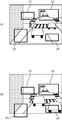
- FIG. 5 is a diagram illustrating a time-series image captured by the imaging apparatus according to the embodiment of the present invention.
- the upper row is an image taken at time T
- the lower row is an image taken at time T + ⁇ t, which is ⁇ t after time T.
- a traffic light 34a that is a stationary body
- a pedestrian 31a that is a moving body
- a vehicle 32a and a vehicle 33a
- a traffic light 34b that is a stationary body
- a pedestrian 31b that is a moving body, and a vehicle 32b are present on the image.
- the traffic light 34a and the traffic light 34b are images of the same traffic light, and the traffic light 34b is displayed larger than the traffic light 34a because the imaging unit 1 is closer to the traffic light.
- the pedestrian 31a and the pedestrian 31b are the images of the same pedestrian, and the pedestrian 31b has advanced to the roadway side (right direction in a figure).
- the vehicle 32a and the vehicle 32b are images of the same vehicle, and the vehicle 32b is closer to the traffic signal.
- the vehicle 32b is displayed larger than the vehicle 32a because the imaging unit 1 is approaching the vehicle.
- the same vehicle as the vehicle 32a is not displayed in the image at time T + ⁇ t. Since the vehicle 32a moves in a direction away from the traffic signal 34a, the vehicle 32a moves out of the image range at time T + ⁇ t.
- the image captured by the imaging unit 1 is sent to the tertiary image source information calculation unit 5.
- the 3D image information calculation unit 5 calculates 3D image information of each point in each image (S102). Specifically, the three-dimensional image information calculation unit 5 calculates a two-dimensional optical flow, a three-dimensional coordinate, a three-dimensional optical flow, and the like of each point.
- the stationary body region extraction unit 6 extracts a stationary body region in each image based on the 3D image information from the 3D image information calculation unit 5 (S103). At this time, the operator may directly indicate the stationary body region in the image by using the input unit 4 while viewing each image displayed on the display device 3.
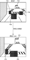
- FIG. 6 is a diagram showing a time-series image in a state where a stationary body region is extracted in one embodiment of the present invention.
- the upper row is an image taken at time T
- the lower row is an image taken at time T + ⁇ t, which is ⁇ t after time T.
- a stationary body region is extracted based on the image of FIG.
- the traffic light 44a which is a stationary body is displayed, but the pedestrian and the vehicle which are moving bodies are displayed as moving body areas 41a, 42a and 43a.
- the displayed image is a stationary body region.
- the traffic light 44b that is a stationary body is displayed, but the pedestrian and the vehicle that are moving bodies are displayed as moving body areas 41b and 42b.
- the integration unit 7 calculates a rotation component and a translation component that transform the image at the time T + ⁇ t so that the still body regions of the images extracted by the stationary body region extraction unit 6 match, and at the time T + ⁇ t.
- the image is converted, and the image at time T and the image at time T + ⁇ t are overlapped to integrate the images (S104).
- the integration unit 7 selects three points or a plurality of points in the stationary body region in the reference image extracted by the stationary body region extraction unit 6, and from the image to be integrated into the image, Three points corresponding to these three points or a plurality of points corresponding to these plural points are searched.
- the integration unit 7 calculates a rotation component and a translation component necessary for coordinate conversion to match a surface constituted by the three points of the reference image with a surface constituted by the three points corresponding thereto. .
- the integration unit 7 calculates a conversion component by using an ICP algorithm when a plurality of points are selected. Then, the integration unit 7 converts the image to be integrated into the reference image using the conversion component, and integrates the converted image and the reference image.
- FIG. 7 is a flowchart for explaining the operation of the integration unit according to the embodiment of the present invention. Specifically, FIG. 7 is a flowchart for explaining the operation of the integration unit 7 in the case where the rotation component and the translation component (conversion component) necessary for coordinate conversion are calculated from three points in the stationary body region. It is. Here, a case where a highly accurate integrated image is required will be described. First, the integration unit 7 selects any three points in the stationary body region in the reference image extracted by the stationary body region extraction unit 6 (S201).
- the integration unit 7 determines whether the three points are on a straight line in the three-dimensional coordinates (S202). If these three points are on a straight line, the process returns to step S201, and the integration unit 7 again selects arbitrary three points. In this case, the integration unit 7 may change only one point, for example. If it is not in a straight line in step S202, the integration unit 7 determines whether these three points are sufficiently separated from each other and these distances are appropriate. Specifically, it is determined whether or not the area of the triangle formed by connecting these three points is 0.8 or more of the maximum area of the triangle that can be formed by the three points in the image.
- the unit 7 searches for three points corresponding to these three points from the image to be integrated with the image (S204).
- the integration unit 7 rotates and translates components (for conversion) necessary for coordinate transformation to match a surface constituted by three points of the reference image with a surface constituted by the three points corresponding thereto. Component) is calculated (step S205). Then, the integration unit 7 converts the image to be integrated into the reference image using the conversion component (step S206), and integrates the converted image and the reference image (step S207).
- the color of the lamp of the traffic light may be the color of the lamp having the maximum brightness among the lamps of the traffic light of each image.
- FIG. 8 is a diagram illustrating an image integrated in an embodiment of the present invention
- FIG. 8A is a diagram illustrating an integrated image based on an image captured by the imaging unit
- FIG. It is a figure which shows the image which converted the image into the bird's-eye view display.
- the stationary object regions including the traffic lights 54 in both images are coincident and overlapped, but there are two vehicles 52a and 52b and vehicles 53a and 53b which are moving objects. That is, the vehicle 52a and the vehicle 52b are displays of the same vehicle.
- the vehicle 52a is at time T
- the vehicle 52b is at time T + ⁇ t.
- the vehicle 53a and the vehicle 53b are displays of the same vehicle.
- the vehicle 53a is at time T
- the vehicle 53b is at time T + ⁇ t.
- the pedestrian 51 is also a moving object, since the moving speed is slower than that of the vehicle and hardly moves during ⁇ t, the pedestrian 51 is superimposed and displayed.
- this integrated image has three-dimensional image information, it can be converted into an image viewed from a different direction.
- a bird's-eye view display is also possible.
- the distance between the vehicle 53a and the vehicle 53b is longer than the distance between the vehicle 52a and the vehicle 52b. Accordingly, the speed of the vehicles 53a and 53b is faster than that of the vehicles 52a and 52b.
- the integrated image obtained by the image integration device according to the present embodiment matches the time-series images in the stationary body region, the movement of the moving object is easy to understand, and the operation state of the vehicle or the like can be easily seen at a glance. Recognize. Therefore, by using this integrated image, there is an effect that situation analysis such as an accident can be easily performed.
- the imaging unit of the image integration device according to the present embodiment can be used by being mounted on a vehicle or the like, the imaging location is not limited.
- An image integration device is mounted on a moving body, based on an imaging unit that captures a plurality of time-series images at different times, and the time-series image captured by the imaging unit, A three-dimensional image information calculation unit that calculates three-dimensional image information in each time-series image; a stationary body region extraction unit that extracts a stationary body region in each time-series image based on the three-dimensional image information; From each stationary body region extracted in each time-series image, calculate the corresponding stationary body region between each time-series image, and integrate the time-series images by matching the corresponding stationary body regions. And an integration unit.
- the image integration device integrates these images with reference to stationary body regions in a plurality of temporally different images, so that accurate image integration is possible.
- the image integration device also has an effect of being able to obtain an integrated image that can grasp the motion of a moving object at a glance.
- the imaging unit can acquire a pair of left and right stereo images, each of the plurality of time-series images is the stereo image, and the three-dimensional image information calculation unit includes: It is preferable that three-dimensional image information in each time-series image is calculated using the stereo image.
- the image integration device obtains 3D image information using a stereo image, it can obtain highly accurate 3D image information.
- the integration unit selects an arbitrary plurality of points in one of the corresponding stationary body regions, and corresponds to the arbitrary plurality of points in the other of the corresponding stationary body regions. It is preferable to calculate a plurality of points to be calculated, and to calculate a rotation component and a translation component that match the plurality of arbitrary points and the plurality of points corresponding to the plurality of arbitrary points.
- the integration unit can easily match the corresponding stationary body regions by using the rotation component and the translation component.
- the plurality of arbitrary points selected in one of the stationary body regions are arbitrary three points
- the calculated point in the other of the corresponding stationary body regions is Preferably, there are three points corresponding to any three points, and the rotation component and the translation component are calculated so that the three points corresponding to the three arbitrary points and the three arbitrary points coincide.
- the integration unit can calculate the rotation component and the translation component using a small number of points, the processing is fast.
- the three arbitrary points are changed according to the respective time-series images to be integrated.
- the three points are selected from points that are surely present on the image to be integrated. Therefore, even if there are a plurality of images to be integrated and the number of images increases as needed, the image integration device can reliably integrate the images.
- the three points are set such that the area of the triangle formed by connecting the three arbitrary points is equal to or greater than a predetermined ratio of the maximum area of the triangle formed by the three points. Preferably it is selected.
- the sum of the three sides of the triangle formed by connecting the three arbitrary points is not less than a predetermined ratio of the maximum of the three sides of the triangle formed by the three points. It is preferable that the three points are selected.
- the integration unit obtains the coincidence of the stationary body region in the local part.
- more accurate stationary can be achieved by separating each point from each other.
- Body region matching can be realized.
- the integration unit uses the ICP algorithm to match the rotation component and the translation that match the plurality of arbitrary points and the plurality of points corresponding to the arbitrary plurality of points. It is preferable to calculate the components.
- the integration unit can perform robust alignment that is less affected by noise at the plurality of corresponding points by using the ICP algorithm.
- the stationary body region extraction unit extracts a stationary body region using a vanishing point of motion.
- the stationary body region extraction unit can easily extract the stationary body region by using the vanishing point of the motion. Further, in order to obtain the vanishing point of motion, it is necessary to obtain an optical flow. However, since the three-dimensional image information calculation unit calculates an optical flow, there is no need to newly calculate an optical flow. Also play.
- the stationary body region extraction unit extracts a stationary body region by pattern recognition or template matching using a landmark.
- the stationary body region extraction unit can extract the stationary body region by a simple method such as pattern recognition or template matching.
- the landmark for example, a landmark whose shape is known in advance, such as a sign, a traffic light, or a signboard, may be used.
- the stationary body region extraction unit extracts a moving body region in the time-series image and extracts a region other than the moving body region in the time-series image as a stationary body region.
- the stationary body region extraction unit can extract the stationary body region using the method of extracting the moving body region.
- the three-dimensional image information calculation unit calculates the three-dimensional image information using a corresponding point search between images, and is frequency-resolved in the corresponding point search, and an amplitude component is calculated. It is preferred to use a suppressed window image pattern.
- the corresponding point search used by the three-dimensional image information calculation unit by suppressing the amplitude component from the frequency component, the corresponding point search having robustness is less likely to be affected by the luminance difference and noise between images. Is possible.
- the frequency decomposition is any one of FFT, DFT, DCT, DST, wavelet transform, and Hadamard transform.
- the three-dimensional image information calculation unit is generally used and performs frequency decomposition by an already established technique, it is possible to reliably perform frequency decomposition.
- the corresponding point search uses a phase-only correlation method.
- the three-dimensional image information calculation unit can search for corresponding points with higher accuracy by using the phase-only correlation method.
- the image integration device further includes a traffic light extraction unit that extracts a traffic light in the time-series image, and the integration unit determines the color of the lamp of the extracted traffic signal in any of the time-series images. It is preferable that the color of the extracted lamp of the traffic light in the image integrated by the integration unit is used.
- the integration unit is an image obtained by integrating the color of the signal lamp in the extracted image having the maximum luminance of the signal lamp among the time-series images by the integration unit. It is preferable that the color of the extracted lamp of the traffic light is used.
- An image integration method is based on the imaging step of capturing a plurality of time-series images at different times while moving, and the time-series images captured by the imaging step.
- a three-dimensional image information calculating step for calculating three-dimensional image information in each time-series image, and a static in each time-series image based on the three-dimensional image information calculated by the three-dimensional image information calculating step. From the stationary body region extracting step for extracting a body region and each stationary body region extracted in each time-series image, the corresponding stationary body region is calculated between the time-series images, and the stationary body region is matched. And an integration step of integrating the time-series images.
- this image integration method also has an effect that it is possible to create an integrated image that can grasp the motion of a moving object at a glance.
- an image integration device and an image integration method for integrating time-series images it is possible to provide an image integration device and an image integration method for integrating time-series images.
Landscapes
- Engineering & Computer Science (AREA)
- Multimedia (AREA)
- Computer Vision & Pattern Recognition (AREA)
- Physics & Mathematics (AREA)
- General Physics & Mathematics (AREA)
- Theoretical Computer Science (AREA)
- Image Analysis (AREA)
- Image Processing (AREA)
- Closed-Circuit Television Systems (AREA)
- Mechanical Engineering (AREA)
Abstract
Description
D1=fB/Δd1・・・(1)
D2=fB/Δd2・・・(2)
Claims (17)
- 移動体に搭載され、異なる時間における複数の時系列画像を撮像する撮像部と、
前記撮像部により撮像された前記時系列画像をもとに、前記各時系列画像における3次元画像情報を算出する3次元画像情報算出部と、
前記3次画像元情報をもとに、前記各時系列画像における静止体領域を抽出する静止体領域抽出部と、
前記各時系列画像において抽出された各静止体領域から、前記各時系列画像間において対応する前記静止体領域を算出し、前記対応する静止体領域を一致させることで、前記時系列画像を統合する統合部とを備えた画像統合装置。 - 前記撮像部は、左右一対のステレオ画像を取得することができ、
前記複数の時系列画像はそれぞれ前記ステレオ画像であって、
前記3次元画像情報算出部は、前記ステレオ画像を用いて、前記各時系列画像における3次元画像情報を算出する請求項1に記載の画像統合装置。 - 前記統合部は、前記対応する静止体領域の一方において任意の複数の点を選択し、前記対応する静止体領域の他方において、前記任意の複数の点に対応する複数の点を算出し、
前記任意の複数の点および前記任意の複数の点に対応する複数の点を一致させるような回転成分および並進成分を算出する請求項1または請求項2に記載の画像統合装置。 - 前記静止体領域の一方において選択される前記任意の複数の点は任意の3点であり、
前記対応する静止体領域の他方において、算出される点は、前記任意の3点に対応する3点であり、
前記回転成分および前記並進成分は、前記任意の3点および前記任意の3点に対応する3点が一致するように算出される請求項3に記載の画像統合装置。 - 前記任意の3点は、統合される前記各時系列画像に応じて、変更される請求項4に記載の画像統合装置。
- 前記任意の3点を結んで形成される三角形の面積が、前記3点により形成される三角形の最大面積の所定の割合以上となるように、前記3点が選択される請求項4に記載の画像統合装置。
- 前記任意の3点を結んで形成される三角形の3辺の和が、前記3点により形成される三角形において最大となる3辺の和の所定の割合以上となるように、前記3点が選択される請求項4に記載の画像統合装置。
- 前記統合部は、ICPアルゴリズムを用いて、前記任意の複数の点および前記任意の複数の点に対応する複数の点を一致させるような前記回転成分および前記並進成分を算出する請求項3に記載の画像統合装置。
- 前記静止体領域抽出部は、動きの消失点を用いて静止体領域を抽出する請求項1または請求項2に記載の画像統合装置。
- 前記静止体領域抽出部は、ランドマークを用いて、パターン認識またはテンプレートマッチングにより、静止体領域を抽出する請求項1または請求項2に記載の画像統合装置。
- 前記静止体領域抽出部は、前記時系列画像中の動体領域を抽出し、前記時系列画像中の前記動体領域以外を静止体領域として抽出する請求項1または請求項2に記載の画像統合装置。
- 前記3次元画像情報算出部は、画像間における対応点探索を用いて、前記3次元画像情報を算出し、
前記対応点探索において、周波数分解され、振幅成分が抑制されたウィンドウの画像パターンを用いる請求項1に記載の画像統合装置。 - 前記周波数分解は、FFT、DFT、DCT、DST、ウエーブレット変換およびアダマール変換のいずれかである請求項12に記載の画像統合装置。
- 前記対応点探索は、位相限定相関法を用いている請求項12に記載の画像統合装置。
- 前記時系列画像中における信号機を抽出する信号機抽出部をさらに備え、
前記統合部は、いずれかの前記時系列画像における前記抽出された信号機のランプの色を、前記統合部により統合された画像における前記抽出された信号機のランプの色とする、請求項1に記載の画像統合装置。 - 前記統合部は、前記時系列画像のうち、前記抽出された信号機のランプの輝度が最大の画像における信号機のランプの色を、前記統合部により統合された画像における前記抽出された信号機のランプの色とする、請求項15に記載の画像統合装置。
- 移動しながら、異なる時間における複数の時系列画像を撮像する撮像工程と、
前記撮像工程により撮像された前記時系列画像をもとに、前記各時系列画像における3次元画像情報を算出する3次元画像情報算出工程と、
前記3次元画像情報算出工程により算出された前記3次元画像情報をもとに、前記各時系列画像における静止体領域を抽出する静止体領域抽出工程と、
前記各時系列画像において抽出された各静止体領域から、前記各時系列画像間において対応する前記静止体領域を算出し、前記静止体領域を一致させることで、前記時系列画像を統合する統合工程とを備えた画像統合方法。
Priority Applications (4)
| Application Number | Priority Date | Filing Date | Title |
|---|---|---|---|
| JP2010503315A JP4553072B1 (ja) | 2009-03-31 | 2009-03-31 | 画像統合装置および画像統合方法 |
| US13/258,974 US9415723B2 (en) | 2009-03-31 | 2009-03-31 | Image integration unit and image integration method |
| PCT/JP2009/056590 WO2010113239A1 (ja) | 2009-03-31 | 2009-03-31 | 画像統合装置および画像統合方法 |
| EP09842595.2A EP2416292A4 (en) | 2009-03-31 | 2009-03-31 | IMAGE INTEGRATION UNIT AND IMAGE INTEGRATION PROCESS |
Applications Claiming Priority (1)
| Application Number | Priority Date | Filing Date | Title |
|---|---|---|---|
| PCT/JP2009/056590 WO2010113239A1 (ja) | 2009-03-31 | 2009-03-31 | 画像統合装置および画像統合方法 |
Publications (1)
| Publication Number | Publication Date |
|---|---|
| WO2010113239A1 true WO2010113239A1 (ja) | 2010-10-07 |
Family
ID=42827571
Family Applications (1)
| Application Number | Title | Priority Date | Filing Date |
|---|---|---|---|
| PCT/JP2009/056590 Ceased WO2010113239A1 (ja) | 2009-03-31 | 2009-03-31 | 画像統合装置および画像統合方法 |
Country Status (4)
| Country | Link |
|---|---|
| US (1) | US9415723B2 (ja) |
| EP (1) | EP2416292A4 (ja) |
| JP (1) | JP4553072B1 (ja) |
| WO (1) | WO2010113239A1 (ja) |
Cited By (3)
| Publication number | Priority date | Publication date | Assignee | Title |
|---|---|---|---|---|
| JP2012123751A (ja) * | 2010-12-10 | 2012-06-28 | Toshiba Alpine Automotive Technology Corp | 車両用画像処理装置および車両用画像処理方法 |
| JP2015011502A (ja) * | 2013-06-28 | 2015-01-19 | 株式会社Jvcケンウッド | 先方状況判定装置、安全運転支援装置 |
| JP2022191334A (ja) * | 2017-02-21 | 2022-12-27 | ヘイリー ブラスウェイト | パーソナルナビゲーションシステム |
Families Citing this family (16)
| Publication number | Priority date | Publication date | Assignee | Title |
|---|---|---|---|---|
| JP2011233039A (ja) * | 2010-04-28 | 2011-11-17 | Sony Corp | 画像処理装置、画像処理方法、撮像装置、およびプログラム |
| PT2447884E (pt) * | 2010-10-28 | 2015-02-27 | Cyclomedia Technology B V | Método para detectar e reconhecer um objecto numa imagem e aparelho e programa de computador para o mesmo |
| JP5110235B1 (ja) * | 2011-06-27 | 2012-12-26 | コニカミノルタホールディングス株式会社 | 画像処理装置、画像処理方法、およびプログラム |
| US20140297575A1 (en) * | 2013-04-01 | 2014-10-02 | Google Inc. | Navigating through geolocated imagery spanning space and time |
| US9990004B2 (en) * | 2013-04-02 | 2018-06-05 | Samsung Dispaly Co., Ltd. | Optical detection of bending motions of a flexible display |
| US10331733B2 (en) | 2013-04-25 | 2019-06-25 | Google Llc | System and method for presenting condition-specific geographic imagery |
| US9672223B2 (en) | 2013-04-25 | 2017-06-06 | Google Inc. | Geo photo searching based on current conditions at a location |
| US9488483B2 (en) * | 2013-05-17 | 2016-11-08 | Honda Motor Co., Ltd. | Localization using road markings |
| WO2014192487A1 (ja) * | 2013-05-29 | 2014-12-04 | 日本電気株式会社 | 多眼撮像システム、取得画像の合成処理方法、及びプログラム |
| US9098754B1 (en) | 2014-04-25 | 2015-08-04 | Google Inc. | Methods and systems for object detection using laser point clouds |
| JP6658054B2 (ja) * | 2016-02-16 | 2020-03-04 | トヨタ車体株式会社 | 車体部品の施工部位判定システム及び施工部位判定方法 |
| US10688662B2 (en) | 2017-12-13 | 2020-06-23 | Disney Enterprises, Inc. | Robot navigation in context of obstacle traffic including movement of groups |
| DE102018133461A1 (de) * | 2018-12-21 | 2020-06-25 | Man Truck & Bus Se | Positionsbestimmungssystem und Verfahren zum Betreiben eines Positionsbestimmungssystems für eine mobile Einheit |
| DE102019117559A1 (de) * | 2019-06-28 | 2020-12-31 | Connaught Electronics Ltd. | Verfahren und System zum Fusionieren von zweidimensionalen semantischen Informationen aus Bildern mit einer dreidimensionalen Punktwolke |
| JP7446756B2 (ja) * | 2019-10-02 | 2024-03-11 | キヤノン株式会社 | 画像処理装置、画像処理方法、及びプログラム |
| CN116071945A (zh) * | 2021-10-29 | 2023-05-05 | 通用汽车环球科技运作有限责任公司 | 交通灯可见性检测和增强显示 |
Citations (6)
| Publication number | Priority date | Publication date | Assignee | Title |
|---|---|---|---|---|
| JPH07174538A (ja) | 1993-12-20 | 1995-07-14 | Minolta Co Ltd | 画像入力カメラ |
| JPH07334800A (ja) | 1994-06-06 | 1995-12-22 | Matsushita Electric Ind Co Ltd | 車両認識装置 |
| JP2000244897A (ja) * | 1999-02-16 | 2000-09-08 | Mitsubishi Electric Inf Technol Center America Inc | 状態認識システムおよび状態認識表示生成方法 |
| WO2004008744A1 (ja) * | 2002-07-12 | 2004-01-22 | Iwane Laboratories, Ltd. | 道路面等の平面対象物映像の平面展開画像処理方法、同逆展開画像変換処理方法及びその平面展開画像処理装置、逆展開画像変換処理装置 |
| JP2004102426A (ja) | 2002-09-05 | 2004-04-02 | Mitsubishi Electric Engineering Co Ltd | 交通事故記録映像解析システム |
| JP2006134035A (ja) | 2004-11-05 | 2006-05-25 | Fuji Heavy Ind Ltd | 移動物体検出装置および移動物体検出方法 |
Family Cites Families (4)
| Publication number | Priority date | Publication date | Assignee | Title |
|---|---|---|---|---|
| US5668631A (en) | 1993-12-20 | 1997-09-16 | Minolta Co., Ltd. | Measuring system with improved method of reading image data of an object |
| US6407817B1 (en) | 1993-12-20 | 2002-06-18 | Minolta Co., Ltd. | Measuring system with improved method of reading image data of an object |
| CN1160210C (zh) * | 1999-09-20 | 2004-08-04 | 松下电器产业株式会社 | 驾驶提醒装置 |
| JP4989557B2 (ja) * | 2008-02-05 | 2012-08-01 | 矢崎総業株式会社 | 交通事故解析装置、交通事故解析方法、及びプログラム |
-
2009
- 2009-03-31 JP JP2010503315A patent/JP4553072B1/ja not_active Expired - Fee Related
- 2009-03-31 EP EP09842595.2A patent/EP2416292A4/en not_active Withdrawn
- 2009-03-31 US US13/258,974 patent/US9415723B2/en not_active Expired - Fee Related
- 2009-03-31 WO PCT/JP2009/056590 patent/WO2010113239A1/ja not_active Ceased
Patent Citations (6)
| Publication number | Priority date | Publication date | Assignee | Title |
|---|---|---|---|---|
| JPH07174538A (ja) | 1993-12-20 | 1995-07-14 | Minolta Co Ltd | 画像入力カメラ |
| JPH07334800A (ja) | 1994-06-06 | 1995-12-22 | Matsushita Electric Ind Co Ltd | 車両認識装置 |
| JP2000244897A (ja) * | 1999-02-16 | 2000-09-08 | Mitsubishi Electric Inf Technol Center America Inc | 状態認識システムおよび状態認識表示生成方法 |
| WO2004008744A1 (ja) * | 2002-07-12 | 2004-01-22 | Iwane Laboratories, Ltd. | 道路面等の平面対象物映像の平面展開画像処理方法、同逆展開画像変換処理方法及びその平面展開画像処理装置、逆展開画像変換処理装置 |
| JP2004102426A (ja) | 2002-09-05 | 2004-04-02 | Mitsubishi Electric Engineering Co Ltd | 交通事故記録映像解析システム |
| JP2006134035A (ja) | 2004-11-05 | 2006-05-25 | Fuji Heavy Ind Ltd | 移動物体検出装置および移動物体検出方法 |
Non-Patent Citations (3)
| Title |
|---|
| "A moving object recognition method by principal component analysis", SPECIAL INTEREST GROUP TECHNICAL REPORTS OF IPS - COMPUTER VISION AND IMAGE MEDIA, vol. 1996, no. 31, 1995 |
| HITOSHI KIYA: "Dynamic Image Processing for Real Application", 2007, FACULTY OF SYSTEM DESIGN, article "Integration of image signal processing and image pattern recognition - DCT code-only correlation and application thereof", pages: 3.8 - 3.9 |
| See also references of EP2416292A4 |
Cited By (5)
| Publication number | Priority date | Publication date | Assignee | Title |
|---|---|---|---|---|
| JP2012123751A (ja) * | 2010-12-10 | 2012-06-28 | Toshiba Alpine Automotive Technology Corp | 車両用画像処理装置および車両用画像処理方法 |
| JP2015011502A (ja) * | 2013-06-28 | 2015-01-19 | 株式会社Jvcケンウッド | 先方状況判定装置、安全運転支援装置 |
| JP2022191334A (ja) * | 2017-02-21 | 2022-12-27 | ヘイリー ブラスウェイト | パーソナルナビゲーションシステム |
| US11705018B2 (en) | 2017-02-21 | 2023-07-18 | Haley BRATHWAITE | Personal navigation system |
| US12154451B1 (en) | 2017-02-21 | 2024-11-26 | Haley BRATHWAITE | Personal navigation system |
Also Published As
| Publication number | Publication date |
|---|---|
| US20120013713A1 (en) | 2012-01-19 |
| JPWO2010113239A1 (ja) | 2012-10-04 |
| US9415723B2 (en) | 2016-08-16 |
| EP2416292A4 (en) | 2014-09-03 |
| JP4553072B1 (ja) | 2010-09-29 |
| EP2416292A1 (en) | 2012-02-08 |
Similar Documents
| Publication | Publication Date | Title |
|---|---|---|
| JP4553072B1 (ja) | 画像統合装置および画像統合方法 | |
| JP4406381B2 (ja) | 障害物検出装置及び方法 | |
| JP4609603B2 (ja) | 3次元情報表示装置および3次元情報表示方法 | |
| JP5109691B2 (ja) | 解析装置 | |
| JP4363295B2 (ja) | ステレオ画像による平面推定方法 | |
| JP5267596B2 (ja) | 移動体検出装置 | |
| JP5267330B2 (ja) | 画像処理装置および方法 | |
| JP6515704B2 (ja) | 車線検出装置及び車線検出方法 | |
| EP3324359B1 (en) | Image processing device and image processing method | |
| US11087150B2 (en) | Detection and validation of objects from sequential images of a camera by using homographies | |
| JP2015175598A (ja) | 画像処理装置 | |
| JP6552448B2 (ja) | 車両位置検出装置、車両位置検出方法及び車両位置検出用コンピュータプログラム | |
| JP4553071B1 (ja) | 3次元情報表示装置および3次元情報表示方法 | |
| KR20190134303A (ko) | 영상 인식 장치 및 그 방법 | |
| Fregin et al. | Three ways of using stereo vision for traffic light recognition | |
| JP2005217883A (ja) | ステレオ画像を用いた道路平面領域並びに障害物検出方法 | |
| JP4946896B2 (ja) | 距離計測装置及び距離計測方法 | |
| JP2009092551A (ja) | 障害物計測方法、障害物計測装置及び障害物計測システム | |
| JP5472928B2 (ja) | 対象物検出装置及び方法 | |
| JP6886136B2 (ja) | 位置合わせ装置、位置合わせ方法及び位置合わせ用コンピュータプログラム | |
| EP3168779A1 (en) | Method for identifying an incoming vehicle and corresponding system | |
| JP5256508B2 (ja) | 3次元情報算出装置および3次元情報算出方法 | |
| JP4762026B2 (ja) | 道路標識データベース構築装置 | |
| JP4946898B2 (ja) | 距離計測装置及び距離計測方法 | |
| JP2025041151A (ja) | 車載画像処理装置 |
Legal Events
| Date | Code | Title | Description |
|---|---|---|---|
| WWE | Wipo information: entry into national phase |
Ref document number: 2010503315 Country of ref document: JP |
|
| 121 | Ep: the epo has been informed by wipo that ep was designated in this application |
Ref document number: 09842595 Country of ref document: EP Kind code of ref document: A1 |
|
| WWE | Wipo information: entry into national phase |
Ref document number: 13258974 Country of ref document: US |
|
| NENP | Non-entry into the national phase |
Ref country code: DE |
|
| REEP | Request for entry into the european phase |
Ref document number: 2009842595 Country of ref document: EP |
|
| WWE | Wipo information: entry into national phase |
Ref document number: 2009842595 Country of ref document: EP |