WO2010113336A1 - 広帯域アンテナ - Google Patents
広帯域アンテナ Download PDFInfo
- Publication number
- WO2010113336A1 WO2010113336A1 PCT/JP2009/063698 JP2009063698W WO2010113336A1 WO 2010113336 A1 WO2010113336 A1 WO 2010113336A1 JP 2009063698 W JP2009063698 W JP 2009063698W WO 2010113336 A1 WO2010113336 A1 WO 2010113336A1
- Authority
- WO
- WIPO (PCT)
- Prior art keywords
- radiating element
- shape
- straight line
- antenna
- shows
- Prior art date
- Legal status (The legal status is an assumption and is not a legal conclusion. Google has not performed a legal analysis and makes no representation as to the accuracy of the status listed.)
- Ceased
Links
Images

















Classifications
-
- H—ELECTRICITY
- H01—ELECTRIC ELEMENTS
- H01Q—ANTENNAS, i.e. RADIO AERIALS
- H01Q9/00—Electrically-short antennas having dimensions not more than twice the operating wavelength and consisting of conductive active radiating elements
- H01Q9/04—Resonant antennas
- H01Q9/30—Resonant antennas with feed to end of elongated active element, e.g. unipole
- H01Q9/40—Element having extended radiating surface
-
- H—ELECTRICITY
- H01—ELECTRIC ELEMENTS
- H01Q—ANTENNAS, i.e. RADIO AERIALS
- H01Q1/00—Details of, or arrangements associated with, antennas
- H01Q1/36—Structural form of radiating elements, e.g. cone, spiral, umbrella; Particular materials used therewith
- H01Q1/38—Structural form of radiating elements, e.g. cone, spiral, umbrella; Particular materials used therewith formed by a conductive layer on an insulating support
-
- H—ELECTRICITY
- H01—ELECTRIC ELEMENTS
- H01Q—ANTENNAS, i.e. RADIO AERIALS
- H01Q9/00—Electrically-short antennas having dimensions not more than twice the operating wavelength and consisting of conductive active radiating elements
- H01Q9/04—Resonant antennas
- H01Q9/16—Resonant antennas with feed intermediate between the extremities of the antenna, e.g. centre-fed dipole
- H01Q9/28—Conical, cylindrical, cage, strip, gauze, or like elements having an extended radiating surface; Elements comprising two conical surfaces having collinear axes and adjacent apices and fed by two-conductor transmission lines
-
- H—ELECTRICITY
- H01—ELECTRIC ELEMENTS
- H01Q—ANTENNAS, i.e. RADIO AERIALS
- H01Q9/00—Electrically-short antennas having dimensions not more than twice the operating wavelength and consisting of conductive active radiating elements
- H01Q9/04—Resonant antennas
- H01Q9/30—Resonant antennas with feed to end of elongated active element, e.g. unipole
- H01Q9/42—Resonant antennas with feed to end of elongated active element, e.g. unipole with folded element, the folded parts being spaced apart a small fraction of the operating wavelength
Definitions
- the present invention relates to a broadband antenna, and more particularly, to a broadband antenna for UWB (Ultra Wide Band).
- UWB Ultra Wide Band
- UWB Wireless communication using UWB is attracting attention as an ultra-wideband high-capacity communication means.
- UWB was approved for use in the frequency range from 3.1 GHz to 10.6 GHz in 2002 according to the FCC (Federal Communications Commission) standard in the United States.
- FCC Federal Communications Commission
- the antenna used for UWB communication is required to have an ultra-wideband and small structure.
- an antenna in which the second radiating element and the first radiating element are arranged on the same plane has been proposed (for example, see Patent Document 1).
- the second radiating element and the first radiating element are arranged on the same plane, a loop is formed in the second radiating element, and the area of the first radiating element is smaller than that of the second radiating element. It is getting bigger.
- the VSWR Voltage Standing Wave Ratio
- the VSWR Voltage Standing Wave Ratio
- An antenna having a three-dimensional structure such as a biconical (for example, see Non-Patent Document 1), a discon (for example, see Non-Patent Document 2), a planar bow-tie monopole (for example, see Non-Patent Document 3),
- An antenna having a planar structure such as a planar square dipole (for example, see Non-Patent Document 4), an elliptical monopole (for example, see Non-Patent Document 5), or a monopole in which a planar square radiating element is wound in a roll shape ( For example, refer nonpatent literature 6.) etc. are mentioned.
- An antenna mounted on a small wireless communication terminal is required to be small and compatible with a wide band. Moreover, it is desirable that manufacture is easy. In UWB communication, a stable radiation pattern is required over a wide band.
- the conventional antenna has a biased directivity.
- the conventional three-dimensional antenna could not be easily manufactured.
- a conventional antenna having a planar structure has a large area and is difficult to mount on a small wireless communication terminal. Moreover, the variation of the radiation pattern with respect to the change of the operating frequency is large, and cannot be applied to UWB communication. Since a conventional monopole in which a planar square radiating element is wound in a roll shape is wound with a simple radiating element, the operating band is limited. Moreover, the winding method is only a roll shape and may not be suitable for mass production.
- an object of the present invention is to provide an antenna having a small size, capable of supporting a wide band, and having stable radiation characteristics over a wide band.
- the inventors have experimentally bent the second radiating element and the first radiating element about the arrangement direction of the second radiating element and the first radiating element in a wideband antenna in which the second radiating element and the first radiating element are arranged on the same plane. It was discovered that omnidirectionality improved when rolled into a cylindrical shape.
- the wideband antenna according to the present invention includes a first radiating element and a second radiating element, and the second radiating element includes an arrangement direction of the second radiating element and the first radiating element, and It is bent on a substantially parallel first straight line, or is rounded into a cylindrical shape having a straight line substantially parallel to the first straight line as an axial direction.
- the antenna can be downsized and the radiation characteristics of the antenna can be improved by bending or rounding the second radiating element.
- a planar antenna formed of a metal film can be bent or rolled, it is easy to manufacture. Therefore, according to the present invention, it is possible to provide an antenna that is small and can handle a wide band, has a stable radiation characteristic over a wide band, and is easy to manufacture.
- the wideband antenna according to the present invention is a wideband antenna in which the second radiating element and the first radiating element are arranged on the same plane, wherein the second radiating element and the first radiating element are The first radiating element is bent on a straight line substantially parallel to the arrangement direction of the second radiating element and the first radiating element, or a straight line substantially parallel to the first straight line is defined as an axial direction. It is rounded into a cylindrical shape.
- omnidirectionality can be improved in a wideband antenna in which the second radiating element and the first radiating element are arranged on the same plane. Furthermore, since the second radiating element and the first radiating element can be mounted on the information terminal device in a state of being bent or rolled, the information terminal device can be downsized.
- the second radiating element and the first radiating element are in a loop shape, and the outer shape of the second radiating element and the first radiating element is the first radiating element.
- the shape of the outer periphery of the second radiating element and the first radiating element in a proximity portion where the second radiating element and the first radiating element are opposed to each other is It is preferably line symmetric with respect to a second straight line orthogonal to the first straight line.
- a first convex portion in which a part of the outer periphery of the first radiating element is convex in a proximity portion where the second radiating element and the first radiating element face each other, And a second convex part having a convex part on the outer periphery of the second radiating element, and the opposing edges of the first convex part and the second convex part are parallel to each other.
- a second convex part having a convex part on the outer periphery of the second radiating element, and the opposing edges of the first convex part and the second convex part are parallel to each other.
- the omnidirectionality of the antenna is improved by adopting the configuration according to the present invention. Therefore, according to the present invention, the omnidirectionality of the broadband antenna can be improved.
- the second radiating element is configured so that the second radiating element and the first radiating element are located at a position closest to the second radiating element and the first radiating element. Until the position of the predetermined height in the arrangement direction, the width of the second radiating element increases as the distance from the first radiating element increases, and the second radiating element and the first radiating element are increased.
- the width of the projected shape of the second radiating element in the array direction, and the wavelength of the lowest operating frequency is lambda 0, it is preferred that the lateral width is 0.12Ramuda 0 or more 0.5 [lambda 0 or less.
- width of the second radiating element is 0.12Ramuda 0 or more, it is possible to prevent an increase in minimum operating frequency due to coupling that occurs when rounding or folding the second radiating element.
- width of the second radiating element is 0.5 [lambda 0 or less, it is possible to prevent an increase in the size of the antenna. Therefore, according to the present invention, a wide-band and small antenna can be obtained.
- the second radiating element is bent or rounded into two or more layers, and the shortest distance between the layers is 0.005 ⁇ 0 or more, The longest distance between them is preferably 0.1 ⁇ 0 or less.
- the distance between the layers is less than 0.005Ramuda 0, the strong coupling, there is a case where broadband characteristics of the antenna is lost. Further, since the distance between the layers is 0.1 [lambda] 0 or less, it is possible to miniaturize the antenna. Therefore, according to the present invention, a wide-band and small antenna can be obtained.
- the shape of the second radiating element in a cross section perpendicular to the first straight line is a spiral shape, a flat spiral shape, a part of a circular shape, a meander shape, or a combination thereof. It is preferable.
- the wideband antenna according to the present invention can be formed in a shape suitable for mounting while maintaining input characteristics and radiation characteristics.
- the second radiating element is preferably formed by laminating a metal film on a dielectric sheet. Since the dielectric sheet is laminated on one side or both sides of the metal film as the second radiating element, the broadband antenna according to the present invention can be easily manufactured.
- a dielectric block is inserted between the metal films of the second radiating element.
- the broadband antenna according to the present invention can be easily manufactured by inserting the dielectric block between the second radiating elements between the metal films.
- the feeding point of the second radiating element is disposed at an end portion in a direction substantially perpendicular to the arrangement direction of the second radiating element and the first radiating element.
- the second radiating element when the second radiating element is bent or rolled, it is possible to arrange the feeding point inside or to arrange the feeding point outside.
- the feeding point inside radiation by the feeding cable can be suppressed. Thereby, the characteristics of the antenna are improved.
- the feeding cable can be connected after the second radiating element is bent or rounded. This facilitates the manufacture and inspection of the antenna.
- an antenna having a small size and capable of supporting a wide band and having stable radiation characteristics over a wide band.
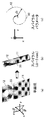
- FIG. 1 is a schematic configuration diagram of a wideband antenna according to Embodiment 1.
- FIG. It is the structure schematic of the state which extended the wideband antenna which concerns on Embodiment 1.
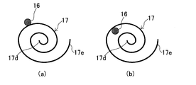
- FIG. It is a first example of a cross-sectional view taken along the line S-S ', (a) shows an example in which a power feeding cable is arranged outside the folded board, and (b) shows an example in which the feeding cable is arranged inside the folded board.
- It is a second example of the SS ′ cross-sectional view, (a) shows an example in which a power feeding cable is arranged outside the substrate rounded into a cylindrical shape, and (b) shows a power feeding cable arranged inside the substrate rounded in a cylindrical shape. An example is shown.
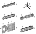
- FIG. It is an example of the shape of the wideband antenna which concerns on Embodiment 2, (a) shows a planar shape, (b) shows a spiral shape, (c) shows a flat spiral shape, (d) shows a circular roll shape. (E) shows the meander shape. It is an example of the shape which looked at the wideband antenna concerning Embodiment 2 from the top, (a) shows a plane shape, (b) shows a spiral shape, (c) shows a flat spiral shape, (d) is A circular roll shape is shown, and (e) shows a meander shape.
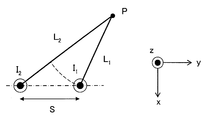
- FIG. 3 is a schematic diagram of radiation at an observation point P.
- FIG. 6 shows application examples of the wideband antenna according to the second embodiment, where (a) shows a first application example to a dipole antenna, (b) shows a second application example to a dipole antenna, and (c) shows a monophonic antenna.
- An example of application to a pole antenna is shown.
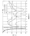
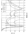
- 10 shows an antenna pattern of a wideband antenna according to a third embodiment. It is a comparative example of the external shape of a 2nd radiation element, (a) shows an antenna pattern in case a 2nd radiation element is glass shape, (b) is an antenna pattern in case a 2nd radiation element is square shape. Indicates. The input characteristics when the second radiating element is glass-shaped and when the second radiating element is quadrangular are shown.
- FIG. 6 is a comparative example of the case where there is an elliptical hole in the broadband antenna according to the third embodiment and FIG. 5A is a schematic diagram of the antenna when there is a hole, and FIG. 5B is the antenna when there is no hole. The schematic of is shown.
- the input characteristics with and without an elliptical hole in the broadband antenna according to the third embodiment are shown.
- the schematic of the antenna at the time of changing the width W2c of the convex part in the wideband antenna which concerns on Embodiment 3 is shown.
- the input characteristic at the time of changing the width W2c of the convex part in the wideband antenna which concerns on Embodiment 3 is shown.
- 7 shows a radiation pattern on the xy plane of a wideband antenna according to a third embodiment.
- 4 shows a wideband antenna according to Embodiment 3, wherein (a) shows a planar antenna pattern, (b) shows a state in which the second radiating element is wound in a spiral shape, and (c) shows a spiral shape. The state which saw the 2nd radiation
- interval of the layer of a spiral is shown.
- 8 shows a radiation pattern on the xy plane at 8 GHz of the wideband antenna according to the third embodiment.
- 4 shows a broadband antenna according to Embodiment 4, wherein (a) shows a planar antenna pattern, (b) shows a state in which the second radiating element is wound in a flat spiral shape, and (c) shows a flat spiral shape. The state which looked at the 2nd radiation
- interval of the layer of a flat spiral is changed is shown.
- 10 shows a radiation pattern on the xy plane at 8 GHz of the wideband antenna according to the fourth embodiment.
- 7 shows a wideband antenna according to Embodiment 5, wherein (a) shows a planar antenna pattern, (b) shows a state where the second radiating element is bent in a meander shape, and (c) shows a meander shape. The state which looked at the 2nd radiation
- interval sm of a meander layer is shown.
- 10 shows a radiation pattern on the xy plane at 8 GHz of the wideband antenna according to the fifth embodiment.
- Embodiment 8 shows a broadband antenna according to Embodiment 6, wherein (a) shows a planar antenna pattern, (b) shows a state in which the second radiating element is rolled into a circular roll, and (c) shows a circular roll. The state which looked at the 2nd radiation
- 8 shows a radiation pattern on the xy plane at 8 GHz of the wideband antenna according to the sixth embodiment.
- 10 shows an antenna pattern of a wideband antenna according to a seventh embodiment.
- Embodiment 8 shows a broadband antenna according to Embodiment 7, wherein (a) shows a planar antenna pattern, (b) shows a state in which the second radiating element is rounded in a spiral shape, and (c) is rounded in a spiral shape. The state which saw the 2nd radiation
- interval ds of the layer of a spiral is 10 mm is shown.
- 10 shows a radiation pattern on the xy plane at 8 GHz of the wideband antenna according to the seventh embodiment.
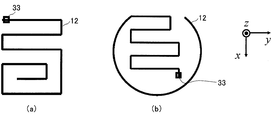
- 9 shows a broadband antenna according to Embodiment 8, wherein (a) shows a case where a feeding point is arranged inside the first radiating element, and (b) shows a feeding point arranged outside the first radiating element. Shows the case.
- FIG. 1 is a schematic configuration diagram of a wideband antenna according to the present embodiment.
- the broadband antenna according to the present embodiment is a broadband antenna in which the second radiating element and the first radiating element are arranged on the same substrate 17, and the substrate 17 is a feeding point 14 of the second radiating element. Is bent on a straight line substantially parallel to the first straight line A connecting the feeding point 13 of the first radiating element, or rounded into a cylinder having a straight line substantially parallel to the first straight line A as an axial direction. It is characterized by being.
- the feeding cable 16 is arranged in parallel with the first straight line A.
- the first straight line A is substantially parallel to the arrangement direction of the second radiating element and the first radiating element.
- FIG. 2 is a schematic configuration diagram of a state in which the broadband antenna according to the present embodiment is expanded.
- the broadband antenna according to the present embodiment includes a first radiating element 11, a second radiating element 12, a feeding point 13 to the first radiating element 11, and a feeding point 14 to the second radiating element 12.
- the 1st convex part 24 and the 2nd convex part 25 are provided.
- the second radiating element 12 and the first radiating element 11 have proximity portions that face each other.
- a part 22 of the outer periphery of the second radiating element 12 and a part 21 of the outer periphery of the first radiating element 11 are opposed to each other to form a proximity portion.
- the outer conductor of the power feeding cable is connected to the terminal of the feeding point 13 of the first radiating element 11.
- the inner conductor of the power feeding cable is connected to the terminal of the feeding point 14 of the second radiating element 12.
- the second radiating element 12 and the first radiating element 11 are arranged on the same plane.
- the second radiating element 12 and the first radiating element 11 are formed on a common substrate 17.
- the substrate material may be an insulator such as polyimide, but may be a dielectric such as epoxy resin or acrylic resin.
- the broadband antenna according to the present embodiment can be downsized while obtaining good VSWR characteristics even if the substrate material is an insulator. Since the substrate material is a dielectric, the broadband antenna can be further reduced in size.
- the second radiating element 12 and the first radiating element 12 are formed on a dielectric substrate material such as an FR-4 printed circuit board or an acrylic resin.
- the radiating element 11 can also be affixed with an adhesive substance.
- the radiating element is formed of a conductive thin film such as a metal film.
- the outer peripheral shapes of the second radiating element 12 and the first radiating element 11 are axisymmetric with respect to the first straight line A.
- the outer peripheral shape of the second radiating element 12 and the first radiating element 11 is an ellipse
- the minor axis of the ellipse is arranged on the first straight line A.
- the outer peripheral shape of the second radiating element 12 and the first radiating element 11 is not limited to an ellipse, and may be a circle, an ellipse, a polygon, or a combination thereof.
- the center points of the outer peripheral shapes of the second radiating element 12 and the first radiating element 11 are arranged on the first straight line A. It is preferable that the second radiating element 12 and the first radiating element 11 are closest to each other on the first straight line A.
- the feeding points 13 and 14 are arranged on the first straight line A. Thereby, it is possible to supply power to a position where the second radiating element 12 and the first radiating element 11 are closest to each other.
- the feeding points 13 and 14 are preferably arranged at a position equidistant from the second straight line B.
- the distance between the feeding point 13 and the feeding point 14 is preferably 0.2 mm or more, and more preferably approximately 0.35 mm.
- the first convex portion 24 is a portion where a part of the outer periphery of the first radiating element 11 is convex.
- the second convex portion 25 is a portion where a part of the outer periphery of the second radiating element 12 is convex.
- the 1st convex part 24 and the 2nd convex part 25 are arrange
- the first radiating element 12 and the second radiating element 11 are closest to each other. It is preferable to arrange in the part.
- the second radiating element 12 and the first radiating element 11 are disposed on a first straight line A that crosses the centers of the first radiating element 12 and the first radiating element 11.
- FIG. 3 is a first example of the SS ′ cross-sectional view shown in FIG. 1.
- FIG. 3A is an example in which a power feeding cable is arranged outside the folded board
- FIG. 3B is a power feeding cable inside the folded board.
- An example in which is arranged is shown.
- the S-S ′ cross-sectional view shows a cross-sectional view in a cross section passing through S-S ′ shown in FIG. 1 and perpendicular to the first straight line A.
- the first example of the S-S ′ sectional view is bent on a straight line substantially parallel to the first straight line A shown in FIGS. 1 and 2. Even when the second radiating element 12 and the first radiating element 11 shown in FIG. 2 are arranged on the bent substrates 17a, 17b and 17c, the omnidirectionality of the broadband antenna is improved. Can do.
- the thickness of the folded substrate 17b, the substrate 17a, and the substrate 17c can be reduced by arranging the power supply cable 16 on the folded outer side.
- the power feeding cable 16 is arranged inside the folded side, the protruding portion of the power feeding cable 16 is eliminated, so that the broadband antenna can be easily mounted on the information terminal device.
- the broadband antenna shown in FIGS. 3A and 3B is bent so that the bent substrate 17b, the substrate 17a, and the substrate 17c sequentially overlap three.
- the number of overlapping in the wideband antenna according to the present embodiment is not limited.
- the number of overlapping sheets is preferably an odd number such as 3, 5, 7 or the like.
- the fold between the folded substrates is preferably a line-symmetric straight line with the first straight line A as the center line.
- the bent substrate 17a and the substrate 17b adjacent to the substrate 17a are not in contact with each other from the viewpoint of improving omnidirectionality. Therefore, as shown in FIG.3 (b), it is preferable that the electric power feeding cable 16 is arrange
- the second radiating element and the first radiating element shown in FIG. 2 may be arranged on the inner surface to be bent, or may be arranged on the outer surface to be bent.
- a through hole may be provided in the substrate 17, and the feeding cable 16 may be disposed on a surface opposite to the surface on which the second radiating element and the first radiating element are disposed.
- FIG. 4 is a second example of the SS ′ cross-sectional view shown in FIG. 1.
- FIG. 4A is an example in which a power feeding cable is arranged outside a substrate rounded into a cylindrical shape
- FIG. 4B is a rounded shape in a cylindrical shape.
- substrate is shown.
- the second example of the S-S ′ sectional view is rounded into a cylindrical shape having a straight line substantially parallel to the first straight line A shown in FIGS. 1 and 2 as the axial direction.
- the second radiating element 12 and the first radiating element 11 shown in FIG. 2 are arranged on the substrate 17d arranged on the axial side of the cylinder and the substrate 17e arranged on the outer peripheral side of the cylinder.
- the omnidirectionality of the broadband antenna can be improved.
- the outer diameter of the rounded substrate 17 can be reduced by arranging the power supply cable 16 on the rounded outside.
- the feeding cable 16 is arranged inside the rounded side, the protruding portion of the feeding cable 16 is eliminated, so that the broadband antenna can be easily mounted on the information terminal device.
- the number of times the substrate 17 circulates in the wideband antenna according to the present embodiment is not limited.
- the substrate 17d disposed on the axial side of the cylinder and the substrate 17e disposed on the outer peripheral side of the cylinder may be less than one round.
- the number of times that the substrate 17 circulates may be three or more in addition to one, 1.5, 2, and 2.5.
- the outer diameter of the rounded substrate 17 can be made to circulate as small as the outer diameter of the power supply cable 16. This eliminates the need for a chip on which an antenna is mounted, and enables mounting of a broadband antenna on an information terminal device by winding it around various cables such as a LAN (Local Area Network).
- LAN Local Area Network
- the second radiating element and the first radiating element shown in FIG. 2 may be arranged on the rounded inner surface as in the first example of the SS ′ cross-sectional view shown in FIG. However, it may be arranged on the rounded outer surface.
- a through hole may be provided in the substrate 17, and the feeding cable 16 may be disposed on a surface opposite to the surface on which the second radiating element and the first radiating element are disposed.
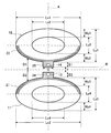
- FIG. 5 is a pickup diagram of the second radiating element and the first radiating element.
- Lx1 is the long diameter of the outer periphery of the second radiating element 12
- Ly1 is the short diameter of the outer periphery of the second radiating element 12
- Lx2 is the long diameter of the inner periphery of the second radiating element 12
- Ly2 is the length of the second radiating element 12.
- the short diameter of the inner periphery, Lx3 is the long diameter of the outer periphery of the first radiating element 11
- Ly3 is the short diameter of the outer periphery of the first radiating element 11
- Lx4 is the long diameter of the inner periphery of the first radiating element 11
- Ly4 is the first This is the minor axis of the inner periphery of one radiation element 11.
- Wy1 is the width from the inner circumference to the outer circumference of the second radiating element 12 on the side far from the second straight line B
- Wy2 is the width from the inner circumference to the outer circumference of the second radiating element 12 on the side closer to the second straight line B.
- the width, Wy3 is the width from the inner periphery to the outer periphery of the first radiating element 11 on the side close to the second straight line B
- Wy4 is the inner periphery to the outer periphery of the first radiating element 11 on the side farther from the second straight line B. It is a width up to.
- D1 is a distance between the second straight line B and a part 22 of the outer periphery of the second radiating element 12
- D2 is a distance between the second straight line B and a part 21 of the outer periphery of the first radiating element 11.
- the second radiating element 12 has a loop shape.
- the structure is such that the conductor at the center of the second radiating element 12 is removed.
- the shape of the inner peripheral portion from which the conductor has been removed can be any shape such as a circle, an ellipse, a polygon more than a triangle, or a combination thereof.
- the first radiating element 11 preferably has a loop shape.
- a plurality of loops may be formed in the first radiating element 11 and the second radiating element 12.
- it may have a shape in which a strip-shaped conductor is provided on the long axis of the inner circumference of one or both of the first radiating element 11 and the second radiating element 12.
- the 1st radiation element 11 and the 2nd radiation element 12 cut
- the shape may be sufficient.
- the outer peripheral shape of the second radiating element 12 and the first radiating element 11 can be an arbitrary shape except for the proximity portion.
- the wideband antenna can be reduced in size by passing the end portions of the proximity portion with a strip-shaped conductor.
- the shape of the outer peripheral portion 22 of the second radiating element 12 and the outer peripheral portion 21 of the first radiating element 11 are symmetrical with respect to the second straight line B.
- the distance D1 and the distance D2 on the straight line parallel to the first straight line A are equal.
- a part 22 of the outer periphery of the second radiating element 12 and a part 21 of the outer periphery of the first radiating element 11 are closest to each other on the first straight line A on the second radiating element 12 and the first radiating element 11. It is preferable to have such a curved shape.
- the shape of the outer peripheral part 22 of the second radiating element 12 and the outer peripheral part 21 of the first radiating element 11 is a part of an ellipse. In this case, the minor axis of the ellipse is arranged on the first straight line A.
- the distance (D1 + D2) between the second radiating element 12 and the first radiating element 11 on the first straight line A that is closest to the second radiating element 12 and the first radiating element 11 is 0.2 mm or more. It is preferable that it is approximately 0.35 mm.
- the outer peripheral shape and inner peripheral shape of the second radiating element 12 are preferably an ellipse in which the minor axis of the ellipse is arranged on the first straight line A.
- the major axis of the outer periphery of the second radiating element 12 is preferably 14 mm or greater and 40 mm or less.
- the ratio of the major axis to the minor axis Lx1: Ly1 and Lx2: Ly2 is preferably 1: 0.3 or more and 1: 0.7 or less. In particular, the ratio of the major axis to the minor axis is preferably 2: 1.
- Ly1 is 40 mm
- Ly1 is preferably 20 mm
- Lx2 is 20 mm
- Ly2 is preferably 10 mm.
- the shape of the outer periphery and the inner periphery of the second radiating element 12 is preferably an ellipse having the same ratio of the major axis to the minor axis, that is, the ellipticity.
- Lx1 / Ly1 Lx2 / Ly2.
- Lx3 / Ly3 Lx4 / Ly4.
- the second radiating element 12 and the first radiating element 11 have the same shape and the same area.
- the shape of the outer periphery and the inner periphery of the second radiating element 12 and the shape of the outer periphery and the inner periphery of the first radiating element 11 are preferably ellipses having the same ellipticity.
- the width from the inner periphery to the outer periphery of the second radiating element 12 and the first radiating element 11 is preferably thicker on the side farther from the side closer to the second straight line B.
- the opposing edges of the first convex portion 24 and the second convex portion 25 are parallel to each other.
- the shape of the opposing edge of the first convex part 24 and the second convex part 25 may be a straight line or a curved line.
- the shape of the opposing edge of the first convex part 24 and the second convex part 25 is a straight line parallel to the second straight line B.
- the second straight line B is a straight line orthogonal to the first straight line A and passing through the centers of the second radiating element 12 and the first radiating element 11. That is, the second straight line B is a direction perpendicular to the direction in which the second radiating element 12 and the first radiating element 11 face each other.
- the shape of the 1st convex part 24 and the 2nd convex part 25 is a part of even-numbered square or more. In this case, it is preferable that a center line passing through the center of one side of the even-numbered square is arranged on the first straight line A.
- the first convex portion 24 and the second convex portion 25 are preferably in a loop shape.
- the loop shape improves the omnidirectionality of the antenna.
- the feeding points 13 and 14 are arranged on the second straight line B side with respect to the loop. Thereby, it is possible to suppress a rapid increase in impedance from the power supply cable to the power supply points 13 and 14.
- the width G of the first convex portion 24 and the second convex portion 25 in the direction parallel to the second straight line B is preferably 3 mm or more and 12 mm or less in the case of a UWB antenna.
- the width G is a width of a portion where the first convex portion 24 and the second convex portion 25 face each other in parallel.
- the distance F between the first convex portion 24 and the second convex portion 25 is preferably 0.2 mm or more and 2 mm or less. Since the distance between the outer edges of the first convex portion 24 and the second convex portion 25 is appropriate, the omnidirectionality of the antenna is improved. When the shape of the outer edge of the first convex part 24 and the second convex part 25 is curved or bent, the first convex part 24 and the second convex part 25 at the closest part It is preferable that the distance between the convex portion 24 and the second convex portion 25 is maintained at 0.2 mm or more and 2 mm or less.
- Example 1 shows the case where the substrate 17 is rotated once
- Example 2 indicates that the substrate 17 is rotated 1.5 times
- Example 3 indicates the case where the substrate 17 is rotated 2.5 times.
- a PET Poly Ethylene Terephthalate
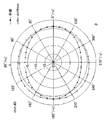
- FIG. 6 shows the measurement results of the directivity of the wideband antenna according to this embodiment.
- the omnidirectionality of the broadband antenna is improved every time the circuit board is overlapped with Example 1, Example 2, and Example 3.
- the omnidirectionality of the broadband antenna was improved by bending the substrate. Therefore, the omnidirectionality can be improved by bending or rounding the broadband antenna in which the second radiating element and the first radiating element are formed on the same plane.
- FIG. 7 is an example of the shape of the broadband antenna according to the present embodiment.
- the broadband antenna according to the present embodiment includes a first radiating element 11 that is connected to the outer conductor of the feeding cable and fed with high-frequency power, and a second radiating element 11 that is fed to the inner conductor of the feeding cable and fed with high-frequency power.
- the radiating element 12 and a feeding point 33 to the second radiating element 12 and the first radiating element 11 are provided.
- the second radiating element 12 and the first radiating element 11 are arranged substantially parallel to the z-axis.
- the internal conductor of the power supply cable is connected to the terminal of the power supply point 33 of the second radiating element 12.
- the outer conductor of the power feeding cable is connected to the terminal of the feeding point 33 of the first radiating element 11.
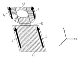
- the second radiating element 12 is bent on a straight line substantially parallel to the z-axis, which is a first straight line substantially parallel to the arrangement direction of the second radiating element 12 and the first radiating element 11, or
- the first straight line is rounded into a cylindrical shape having a straight line substantially parallel to the z-axis as an axial direction.
- the z-axis is rounded into a spiral shape with the z-axis as the axial direction.
- the z-axis is rounded into a flat spiral shape with the axial direction as the axial direction.
- FIG.7 (d) it is rounded by the circular roll shape by making az axis into an axial direction.
- FIG. 7E it is bent into a meander shape on a straight line substantially parallel to the z-axis.
- FIG. 8 is an example of a shape of the wideband antenna according to the present embodiment as viewed from above, (a) shows a planar shape, (b) shows a spiral shape, (c) shows a flat spiral shape, (D) shows a circular roll shape, and (e) shows a meander shape.
- the shape of the second radiating element 12 in the cross section perpendicular to the z-axis is, for example, a spiral shape as shown in FIG. 8B, a flat spiral shape as shown in FIG. 8C, or FIG. It is a part of a circular shape as shown, or a meander shape as shown in FIG.
- the shape of the second radiating element 12 in the cross section perpendicular to the z-axis may be a spiral shape, a flat spiral shape, a part of a circular shape, or a combination of meander shapes.
- a combination of a meander shape and a spiral shape may be used.
- a combination of a meander shape and a circular roll shape may be used.
- the second radiating element 12 is formed by laminating a metal film on a dielectric sheet.
- the substrate on which the second radiating element 12 is formed is formed by sandwiching a dielectric sheet.
- the second radiating element 12 may have a dielectric block inserted between metal films.
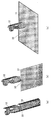
- the feeding point 33 of the second radiating element 12 is substantially the same as the arrangement direction of the second radiating element 12 and the first radiating element 11 as shown in FIGS. 40 (a) and 40 (b) described later. It is preferable to arrange at the end in the vertical direction. In this case, as shown in FIG. 9A, the feeding point 33 of the second radiating element 12 can be arranged outside the second radiating element 12. Alternatively, as shown in FIG. 9B, the feeding point 33 of the second radiating element 12 can be disposed inside the second radiating element 12.
- the proposed broadband antenna is first designed so that the planar film antenna operates in a wide band in its planar state.
- a planar antenna operates in a wide band by an optimized design, it may not be installed in a small wireless device due to its large planar area.
- the planar antenna is usually wide in the y direction in FIG.
- the current flowing on the antenna is characterized by being concentrated on the metal edge. As shown in FIG. 10, the currents I 1 and I 2 flowing near the edges of the second radiating element 12 and the first radiating element 11 are mainly Can be considered as a current source.
- the radiation at the observation point P varies greatly depending on the relative position to the antenna. That, P point The more y-axis direction, the difference between the distance L 2 from the distance L 1 and the current source I 2 from the current source I 1 is increased.
- the distance S between the current sources is in the wavelength order, the current sources I 1 and I 2 have a phase difference in their contribution to radiation, and the radiation pattern in the xy plane is not omnidirectional.
- a disadvantageous situation arises in communication, such as a time difference occurring in the pulse reaching the point P, resulting in a large pulse width. This effect becomes more prominent as the operating frequency increases.
- the distances L 1 and L 2 are equal in the x direction and different in the y direction, so the radiation gain in the y direction is smaller than the x direction.
- the planar antenna is bent or rolled as shown in FIG.
- the antenna becomes compact and not only can be easily accommodated in a small wireless device, but also the distance S between the edges of the antenna of FIG. 11 can be reduced, and the above phase difference can be reduced.
- the radiation pattern of the antenna can be improved, but also the influence on pulse communication can be suppressed.
- the planar antenna when the planar antenna is bent, each part of the antenna is relatively brought close to each other, so that the coupling between the antenna parts is strengthened, and the antenna input characteristics may be deteriorated accordingly.
- the effect can be reduced by optimizing the characteristics of the planar antenna.
- the above coupling occurs mainly in a long wavelength region (low frequency), so when optimizing a planar antenna, especially when the antenna is bent, if the matching is sufficiently improved in the low frequency region. It is possible to minimize the deterioration of the input characteristics that occur.
- the planar antenna needs to have a sufficient width.
- the width is increased, the operating frequency band is increased.
- a structure in which the width gradually increases from the feeding point toward the tip of the radiating element is necessary.
- matching is improved in a high frequency region.
- it is desirable that the area where the two radiating elements face each other is wide near the feeding point. Similarly, the bandwidth becomes wider.
- the hole is opened so that either or both of the radiating elements are in a loop shape. Similarly, the bandwidth becomes wider.
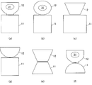
- the planar antenna can be used in various shapes as shown in FIG.
- the second radiating element 12 may have a glass shape as shown in FIGS. 12A and 12F, or may have an elliptical shape as shown in FIG.
- a trapezoidal shape as shown in FIGS. 12C and 12E may be used, or a semi-elliptical shape as shown in FIG.
- the shape of the second radiating element 12 and the first radiating element 11 may be the same type as shown in FIG. 12 (e), or similar in shape as shown in FIG. 12 (f). Alternatively, they may be different as shown in FIGS. 12 (a), 12 (b), 12 (c) and 12 (d).
- the horizontal widths of the second radiating element 12 and the first radiating element 11 are not necessarily the same, and may be different as shown in FIG.
- FIG. 13 shows an application example of the wideband antenna according to the present embodiment, where (a) shows a first application example to a dipole antenna, (b) shows a second application example to a dipole antenna, c) shows an application example to a monopole antenna.
- a dipole both the second radiating element 12 and the first radiating element 11 are bent or rolled as shown in FIG. 13A, and the second radiating element 12 is shown in FIG. 13B.
- the second radiating element 12 is bent or rounded as shown in FIG.
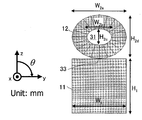
- FIG. 14 shows an antenna pattern of the wideband antenna according to this embodiment.
- the wideband antenna according to the present embodiment is devised so that the matching is improved not only in a wide band but also in a low frequency region.
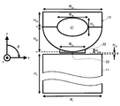
- the second radiating element 12 has a glass-like outer shape
- the second radiating element 12 has an elliptical hole 31 in a loop shape, a semi-elliptical outer shape, and a vicinity of the feeding point 33. Is provided with a trapezoidal convex portion 32.
- the outer shape such as glass is, for example, a predetermined height from the position where the second radiating element 12 and the first radiating element 11 are closest to each other in the arrangement direction of the second radiating element 12 and the first radiating element 11. Up to the position of H 2a , the width of the second radiating element 12 increases as the distance to the first radiating element 11 increases.
- the width W 2a of the second radiating element 12 is 20 mm
- the height H 2a is 8 mm
- the height H 2b is 5 mm
- the width W 2b 9 mm of the hole 31
- the height H 2c 6 mm of the hole 31
- the width W 2c 8 mm of the convex portion 32
- the height H 2c 1.6 mm of the convex portion 32
- the distance H 12 of one radiating element 11 is 0.1 mm
- the width W 1 of the first radiating element 11 is 20 mm
- the height H 1 of the first radiating element 11 is 20 mm.
- FIG. 15A and 15B are comparative examples of the outer shape of the second radiating element, in which FIG. 15A shows an antenna pattern when the second radiating element has a glass shape, and FIG. 15B shows the second radiating element having a square shape. The antenna pattern in the case is shown.
- the second radiating element shown in FIG. 15A and the second radiating element shown in FIG. 15B have the same size and the same width and height.
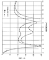
- FIG. 16 shows input characteristics when the second radiating element has a glass shape and when the second radiating element has a square shape.
- the glass-shaped broadband antenna according to the present embodiment has a wider band than the rectangular broadband antenna according to the comparative example, and in a band of 3.1 GHz to 12.5 GHz,
- the characteristic impedance is 50 ⁇ .
- S11 in the following sentence is also based on this characteristic impedance value.
- is ⁇ 12 dB or less, and matching is particularly good. Therefore, by making the antenna pattern of the second radiating element 12 into a glass shape, the input characteristics can be improved as compared with the case where the antenna pattern of the second radiating element is a square shape.
- the size of the antenna is at least one of the two radiating elements and the sum of the width (H 2a + H 2b ) and the width W 2a is 0.25 ⁇ 0 or more. is necessary.
- the width W 2a of the second radiation element 12 is required 0.1 [lambda] 0 or more.
- the sum of the vertical width (H 2a + H 2b ) and the horizontal width W 2a of the second radiating element 12 is 0.3 ⁇ .
- the width W 2a of the second radiating element 12 is preferably 0.12 ⁇ 0 or more.
- the lateral width W 2a indicates the width of the projection shape of the second radiating element 12 in the arrangement direction of the second radiating element 12 and the first radiating element 11.
- the second lateral width of the radiating element 12 is a wider becomes better characteristics, considering the practicality of the dimensional width W 2a of the second radiation element 12 is preferably set to 0.5 [lambda 0 or less.
- the second radiating element 12 when the second radiating element 12 is bent or rounded into two or more layers, if the distance between the closest layers is too close, the broadband characteristic of the antenna is lost due to strong coupling.
- the shortest distance between the layers is at 0.005Ramuda 0 or more, practically 0.01Ramuda 0 or more. From the viewpoint of miniaturization, it is desirable that the maximum distance between the layers is 0.1 [lambda] 0 or less.
- FIG. 17 is a comparative example of the outer shape of the second radiating element, where (a) shows an antenna pattern when the second radiating element has a glass shape, and (b) shows an elliptical shape of the second radiating element.
- the antenna pattern in the case is shown.
- the second radiating element shown in FIG. 17A and the second radiating element shown in FIG. 17B have the same size and the same width and height.
- FIG. 18 shows input characteristics when the second radiating element has a glass shape and when the second radiating element has an elliptical shape. As shown in FIG. 18, compared to the case where the second radiating element shown in FIG. It can be seen that it has an operating band. It can be seen that the band is further widened by introducing the convex portion 32 of the glass-like antenna thereon.
- FIG. 19 is a comparative example with and without an elliptical hole in the wideband antenna according to the third embodiment, where (a) shows a schematic diagram of the antenna with a hole 31 and (b) shows a hole. The schematic of an antenna when there is no is shown.
- FIG. 20 shows input characteristics with and without an elliptical hole in the wideband antenna according to the third embodiment. As shown in FIG. 20, by providing an elliptical hole 31, matching in a high frequency band can be achieved.
- FIG. 21 is a schematic diagram of an antenna when the width W 2c of the convex portion 32 in the wideband antenna according to the third embodiment is changed.
- the broadband antenna according to the present embodiment is optimized so as to operate in UWB while maintaining a planar shape.
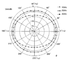
- FIG. 23 shows a radiation pattern on the xy plane of the wideband antenna according to the third embodiment.
- 3 GHz, 5 GHz, and 8 GHz it was relatively round and non-directional at 3 GHz, but it became a shape that collapsed in the y-axis direction as the frequency increased.
- FIG. 24 shows a broadband antenna according to the third embodiment, (a) shows a planar antenna pattern, (b) shows a state in which the second radiating element is wound in a spiral shape, and (c) shows The state which looked at the 2nd radiation element wound spirally from the top is shown.
- the second radiating element 12 and the first radiating element 11 shown in FIG. 14 are spirally wound with a spacing ds between spiral layers.
- This antenna can be easily made by bonding a flexible dielectric sheet having a uniform thickness to a metal film antenna and winding it in a circle.
- FIG. 25 shows the input characteristics of the wideband antenna according to the third embodiment when the spacing of the spiral layers is changed.
- the planar antenna is wound in a spiral shape, the input characteristics are slightly degraded, but the characteristics necessary for UWB wireless communication are maintained.
- ds 3 mm
- FIG. 26 shows a radiation pattern on the xy plane at 8 GHz of the broadband antenna according to the present embodiment.
- the radiation pattern of the spiral wound antenna is more omnidirectional than the planar antenna, and better transmission characteristics can be obtained when UWB wireless communication is performed.
- FIG. 27 shows a broadband antenna according to Embodiment 4, (a) shows a planar antenna pattern, (b) shows a state in which the second radiating element is wound in a flat spiral shape, and (c). Indicates a state of the second radiating element wound in a flat spiral shape as viewed from above.
- the broadband antenna according to the fourth embodiment is different from the second radiating element 12 and the first radiating element 11 shown in FIG. 14 in that the spiral layer spacing in the y direction is ss and the spiral layer spacing in the x direction is ws. It is wound in a flat spiral shape.
- FIG. 28 shows the input characteristics of the wideband antenna according to the fourth embodiment when the interval between the layers of the flat spiral is changed.
- the antenna wound in a flat spiral shape retains the characteristics necessary for UWB wireless communication, although the input characteristics are somewhat degraded.
- FIG. 29 shows a radiation pattern on the xy plane at 8 GHz of the wideband antenna according to the fourth embodiment.
- the radiation pattern of the antenna wound in a flat spiral shape is more omnidirectional than the planar antenna, and better transmission characteristics can be obtained than when performing UWB wireless communication.
- FIG. 30 shows a broadband antenna according to Embodiment 5, (a) shows a planar antenna pattern, (b) shows a state where the second radiating element is bent in a meander shape, and (c) shows A state where the second radiating element is bent in a meander shape and viewed from above is shown.
- the broadband antenna according to the fifth embodiment is different from the second radiating element 12 and the first radiating element 11 shown in FIG. 14 in that the meander width in the y direction and the meander layer spacing sm are constant, and the width wm in the x direction.
- the planar antenna is bent in a meander shape so that is constant.
- the broadband antenna according to the fifth embodiment can be easily manufactured by inserting a dielectric block between the meander layers (gap) of the metal film of the radiating element.
- FIG. 31 shows the input characteristics of the wideband antenna according to Embodiment 5 when the meander layer spacing sm is changed.
- the antenna bent in a meander shape has characteristics necessary for UWB wireless communication, although the input characteristics are somewhat deteriorated.
- sm 1 mm, the characteristics start to deteriorate.
- FIG. 32 shows a radiation pattern on the xy plane at 8 GHz of the wideband antenna according to the fifth embodiment.
- the radiation pattern of the antenna bent in a meander shape is more omnidirectional than the planar antenna, and better transmission characteristics can be obtained when performing UWB wireless communication.
- FIG. 33 shows a wideband antenna according to Embodiment 6, (a) shows a planar antenna pattern, (b) shows a state in which the second radiating element is rolled into a circular roll, and (c) Shows a state in which the second radiating element rounded into a circular roll is viewed from above.
- the broadband antenna according to the sixth embodiment only the second radiating element 12 shown in FIG. 14 is wound in a circular roll shape having a diameter dc.
- FIG. 34 shows the input characteristics of the broadband antenna according to the sixth embodiment when the diameter dc of the circular roll is 8 mm. As shown in the figure, an antenna obtained by rounding the second radiating element 12 into a circular shape retains characteristics necessary for UWB wireless communication, although the input characteristics are somewhat degraded.
- FIG. 35 shows a radiation pattern on the xy plane at 8 GHz of the wideband antenna according to the sixth embodiment.
- the radiation pattern of the antenna in which the second radiating element 12 is rolled into a circular roll shape is more omnidirectional than the planar antenna, and better transmission characteristics can be obtained when performing UWB wireless communication.
- FIG. 36 shows an antenna pattern of the wideband antenna according to the seventh embodiment.
- the outer shape of the second radiating element 12 is elliptical, and an elliptical hole 31 is provided at the center of the second radiating element 12.
- the horizontal width W 2a of the second radiating element 12 is 20 mm
- the height H 2d of the second radiating element 12 is 16 mm
- the horizontal width W 2b of the elliptical hole 31 is 9 mm
- the height H 2c of the elliptical hole 31 is 6 mm
- the horizontal width W 1 of the first radiating element 11 is 20 mm
- the height H 1 of the first radiating element 11 is 20 mm.
- FIG. 37 shows a wideband antenna according to Embodiment 7, (a) shows a planar antenna pattern, (b) shows a state in which the second radiating element is rounded in a spiral shape, and (c) shows The state which looked at the 2nd radiation element rounded in the spiral form from the top is shown.
- the second radiating element 12 shown in FIG. 36 is spirally wound so that the distance ds between the spiral layers is constant.
- FIG. 38 shows the input characteristics of the wideband antenna according to the seventh embodiment when the distance ds between the spiral layers is 10 mm. As shown in the figure, the antenna in which the second radiating element 12 is spirally wound retains the characteristics necessary for UWB wireless communication, although the input characteristics are somewhat degraded.
- FIG. 39 shows a radiation pattern on the xy plane at 8 GHz of the wideband antenna according to the seventh embodiment.
- an antenna rolled in a spiral shape is more omnidirectional than a planar antenna, and better transmission characteristics can be obtained when UWB wireless communication is performed.
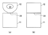
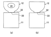
- FIG. 40 shows a wideband antenna according to the eighth embodiment, where (a) shows a case where the feeding point is arranged inside the first radiating element, and (b) shows that the feeding point is more than the first radiating element.
- positions outside is shown.
- the outside refers to the second radiation element when the second radiation element 12 is projected onto the first radiation element 11 in parallel with the arrangement direction of the second radiation element 12 and the first radiation element 11. It means that the width of the element 12 is outside the width of the first radiating element 11.
- the feeding point 33 is disposed inside the first radiating element 11, as shown in FIG. 40A, the second radiating element 12 and the first radiating element 11 are arranged in the z-axis direction.
- the feeding point 33 is disposed at the end of the first radiating element 11 in the y-axis direction.
- the feeding point 33 When the feeding point 33 is disposed outside the first radiating element 11, as shown in FIG. 40B, the second radiating element 12 and the first radiating element 11 are arranged in the z-axis direction.
- the feeding point 33 is disposed outside the end of the first radiating element 11 in the y-axis direction.
- the feeding position when the feeding position is arranged at the end as shown in FIGS. 40A and 40B, the feeding position can be set to the innermost side or the outer side when it is bent.
- the feeding point 33 can be set to the innermost side. In this case, the feeding point 33 can be protected inside the antenna, and radiation by the feeding cable can be suppressed.
- the feeding point 33 can be arranged outside. By doing so, it becomes possible to attach the power supply cable after the antenna is bent, and manufacture and inspection are facilitated.
- This broadband antenna can be made compact by folding a planar antenna made of a metal film, and can be mounted on a small wireless device. In addition, by doing so, the omnidirectionality of the antenna can be improved, and UWB communication can be performed efficiently.
- the present invention can be used for an antenna incorporated in an information terminal device such as a notebook personal computer, a PDA (portable information device) terminal, a mobile phone, or a VICS (Vehicle Information and Communication System).
- an information terminal device such as a notebook personal computer, a PDA (portable information device) terminal, a mobile phone, or a VICS (Vehicle Information and Communication System).
- First radiating element 12 Second radiating elements 13, 14, 33: Feeding point 16: Feeding cable 17: Boards 17a, 17b, 17c: Bent board 17d: Board placed on the axial side of the cylinder 17e: Substrate 21 arranged on the outer peripheral side of the cylinder 21: Part of the outer periphery of the first radiating element 11 22: Part of the outer periphery of the second radiating element 12 24: First convex portion 25: Second convex Part 31: hole 32: convex part
Landscapes
- Details Of Aerials (AREA)
Abstract
本発明は、小型で広帯域に対応でき、かつ、広帯域にわたって放射特性が安定しているアンテナの提供を目的とする。 本発明に係る広帯域アンテナは、第2の放射素子と第1の放射素子が同一の基板17上に配置されている広帯域アンテナであって、基板17は、第2の放射素子と第1の放射素子の配列方向と略平行な第1の直線Aと略平行な直線上で折り曲げられているか、又は、第1の直線Aと略平行な直線を軸方向とする筒状に丸められていることを特徴とする。そして、給電ケーブル16は、第1の直線Aと平行に配置される。
Description
本発明は、広帯域アンテナに関連し、特にUWB(Ultra Wide Band)用広帯域アンテナに関する。
超広帯域での大容量通信手段としてUWBを利用した無線通信が注目されている。UWBは、2002年にアメリカのFCC(Federal Communications Commission)規格により3.1GHzから10.6GHzでの使用が認可された。
UWB通信に用いられるアンテナには、超広帯域でかつ小型の構造が求められる。この要望を満たすため、第2の放射素子と第1の放射素子が同一面上に配置されたアンテナが提案されている(例えば、特許文献1参照。)。
従来のアンテナは、第2の放射素子と第1の放射素子が同一面上に配置され、第2の放射素子にループを形成し、第1の放射素子の面積を第2の放射素子よりも大きくしている。この構成とすることで、およそ3GHz以上の周波数帯域において、VSWR(Voltage Standing Wave Ratio)を2以下としている。
小型な広帯域アンテナが数多く提案されている。バイコニカル(例えば、非特許文献1参照。)、ディスコン(例えば、非特許文献2参照。)のような立体構造をもつアンテナ、平面bow-tie型モノポール(例えば、非特許文献3参照。)、平面四角形ダイポール(例えば、非特許文献4参照。)、楕円型モノポール(例えば、非特許文献5参照。)のような平面構造をもつアンテナ、平面四角放射素子をロール状に巻いたモノポール(例えば、非特許文献6参照。)などが挙げられる。
S.N.Samaddar and E.L.Mokole,"Biconical antennas with unequal cone angles,"IEEE Trans.Antennas Propagat.,vol.46,no.3,pp.436-439,1994
S.S.Sandler and R.W.P.King,"Compact conical antennas for wideband coverage,"IEEE Trans.Antennas Propagat.,vol.42,no.3,pp.436-439,1994
K.L.Shlager,G.S.Smith,and J.G.Maloney,"Optimization of bow-tie antennas for pulse radiation,"IEEE Trans.Antennas Propagat.,vol.42,no.7,pp.975-982,1994
X.H.Wu and Z.N.Chen,"Comparison of planar dipoles in UWB applications,"IEEE Trans.Antennas Propagat.,vol.53,no.6,pp.1973-1983,2005
N.P.Agrawall,G.Kumar,and K.P.Ray,"Wide-band planar monopole antenna,"IEEE Trans.Antennas Propagat.,vol.46,no.2,pp.294-295,1998
Z.N.Chen,"Broadband roll monopole,"IEEE Trans.Antennas Propagat.,vol.51,no.11,pp.3175-3177,2003
小型無線通信端末に搭載するアンテナは、小型で、広帯域に対応できることが要求されている。また、製造が容易であることが望ましい。UWB通信では、広帯域にわたって安定した放射パターンが求められる。
しかし、従来のアンテナは、指向性に偏りが生じていた。
また、従来の立体構造をもつアンテナでは、容易に製造することはできなかった。従来の平面構造をもつアンテナでは、面積が大きく、小型無線通信端末への搭載は困難であった。また、動作周波数の変化に対する放射パターンの変動が大きく、UWB通信に適用することができなかった。従来の平面四角放射素子をロール状に巻いたモノポールは、単純な放射素子を巻いたので、動作帯域が制限されてしまう。また、巻き方がロール状のみであり、大量生産に向かない場合がある。
そこで、本発明は、小型で広帯域に対応でき、かつ、広帯域にわたって放射特性が安定しているアンテナの提供を目的とする。
発明者らは、実験により、第2の放射素子と第1の放射素子が同一面上に配置されている広帯域アンテナにおいて、第2の放射素子と第1の放射素子の配列方向を中心に折り曲げたり筒状に丸めたりしたときに、無指向性が向上することを発見した。
本発明に係る広帯域アンテナは、第1の放射素子と、第2の放射素子と、を備え、前記第2の放射素子は、前記第2の放射素子と前記第1の放射素子の配列方向と略平行な第1の直線上で折り曲げられているか、又は、前記第1の直線と略平行な直線を軸方向とする筒状に丸められていることを特徴とする。
第2の放射素子を折り曲げるか丸めることで、アンテナを小型化するとともに、アンテナの放射特性を向上することができる。また、金属フィルムで形成された平面状のアンテナを折り曲げるか丸めて製造することができるため、製造が容易である。したがって、本発明により、小型で広帯域に対応でき、かつ、広帯域にわたって放射特性が安定しており、かつ、製造が容易なアンテナを提供することができる。
具体的には、本発明に係る広帯域アンテナは、前記第2の放射素子と前記第1の放射素子が同一面上に配置されている広帯域アンテナであって、前記第2の放射素子及び前記第1の放射素子は、前記第2の放射素子と前記第1の放射素子の配列方向と略平行な直線上で折り曲げられているか、又は、前記第1の直線と略平行な直線を軸方向とする筒状に丸められていることを特徴とする。
本発明に係る構成とすることで、第2の放射素子と第1の放射素子が同一面上に配置されている広帯域アンテナにおいて、無指向性を向上することができる。さらに、第2の放射素子及び第1の放射素子を折り曲げたり丸めたりした状態で情報端末機器に実装することができるので、情報端末機器の小型化が可能となる。
本発明に係る広帯域アンテナでは、前記第2の放射素子及び前記第1の放射素子は、ループ状であり、前記第2の放射素子及び前記第1の放射素子の外周の形状は、前記第1の直線に対して線対称であり、前記第2の放射素子と前記第1の放射素子が対向する近接部における前記第2の放射素子及び前記第1の放射素子の外周の形状は、前記第1の直線に直交する第2の直線に対して線対称であることが好ましい。
本発明に係る構成とすることで、アンテナの無指向性を向上することが実験により確認されている。また、本発明に係る構成とすることで、第1の放射素子と第2の放射素子の面積を同一にできることが実験により確認されている。したがって、本発明により、広帯域アンテナの無指向性の向上及び小型化が可能となる。
本発明に係る構成とすることで、アンテナの無指向性を向上することが実験により確認されている。また、本発明に係る構成とすることで、第1の放射素子と第2の放射素子の面積を同一にできることが実験により確認されている。したがって、本発明により、広帯域アンテナの無指向性の向上及び小型化が可能となる。
本発明に係る広帯域アンテナでは、前記第2の放射素子及び前記第1の放射素子が対向する近接部に、前記第1の放射素子の外周の一部を凸状にした第1の凸部、及び、前記第2の放射素子の外周の一部を凸状にした第2の凸部、をさらに備え、前記第1の凸部と前記第2の凸部の対向する縁は、互いに平行であることが好ましい。
本発明に係る構成とすることで、アンテナの無指向性を向上することが実験により確認されている。したがって、本発明により、広帯域アンテナの無指向性の向上が可能となる。
本発明に係る構成とすることで、アンテナの無指向性を向上することが実験により確認されている。したがって、本発明により、広帯域アンテナの無指向性の向上が可能となる。
本発明に係る広帯域アンテナでは、前記第2の放射素子は、前記第2の放射素子と前記第1の放射素子が最も近接する位置から、前記第2の放射素子と前記第1の放射素子の配列方向への所定の高さの位置までは、前記第1の放射素子との距離が大きくなるに従って前記第2の放射素子の幅が広がり、前記第2の放射素子と前記第1の放射素子の配列方向への前記第2の放射素子の投影形状の幅は、最低動作周波数の波長をλ0とすると、横幅が0.12λ0以上0.5λ0以下であることが好ましい。
第2の放射素子の横幅が0.12λ0以上であることで、第2の放射素子を折り曲げるか丸めたときに生じる結合による最低動作周波数の上昇を防ぐことができる。第2の放射素子の横幅が0.5λ0以下であることで、アンテナの大型化を防ぐことができる。したがって、本発明により、広帯域で小型のアンテナにすることができる。
第2の放射素子の横幅が0.12λ0以上であることで、第2の放射素子を折り曲げるか丸めたときに生じる結合による最低動作周波数の上昇を防ぐことができる。第2の放射素子の横幅が0.5λ0以下であることで、アンテナの大型化を防ぐことができる。したがって、本発明により、広帯域で小型のアンテナにすることができる。
本発明に係る広帯域アンテナでは、前記第2の放射素子が2層以上に折り曲げられているか又は丸められており、かつ、層の間の最短距離が0.005λ0以上であり、かつ、層の間の最長距離が0.1λ0以下であることが好ましい。
層の間の距離が0.005λ0未満であると、強結合により、アンテナの広帯域特性が失われてしまう場合がある。また、層の間の距離が0.1λ0以下であることで、アンテナを小型化することができる。したがって、本発明により、広帯域で小型のアンテナにすることができる。
層の間の距離が0.005λ0未満であると、強結合により、アンテナの広帯域特性が失われてしまう場合がある。また、層の間の距離が0.1λ0以下であることで、アンテナを小型化することができる。したがって、本発明により、広帯域で小型のアンテナにすることができる。
本発明に係る広帯域アンテナでは、前記第1の直線と垂直な断面における前記第2の放射素子の形状が、スパイラル形状、扁平スパイラル形状、円形状の一部、又はメアンダ形状或いはこれらの組み合わせであることが好ましい。
本発明により、本発明に係る広帯域アンテナは、入力特性及び放射特性を維持しつつ、実装に適した形状に形成することができる。
本発明により、本発明に係る広帯域アンテナは、入力特性及び放射特性を維持しつつ、実装に適した形状に形成することができる。
本発明に係る広帯域アンテナでは、前記第2の放射素子は、誘電体シート上に金属フィルムが積層されてなることが好ましい。
第2の放射素子が金属フィルムの片面又は両面に誘電体シートが積層されてなることで、本発明に係る広帯域アンテナを容易に製造することができる。
第2の放射素子が金属フィルムの片面又は両面に誘電体シートが積層されてなることで、本発明に係る広帯域アンテナを容易に製造することができる。
本発明に係る広帯域アンテナでは、前記第2の放射素子は、前記金属フィルムの間に誘電体ブロックが挿入されていることが好ましい。
第2の放射素子が金属フィルムの間に誘電体ブロックが挿入されてなることで、本発明に係る広帯域アンテナを容易に製造することができる。
第2の放射素子が金属フィルムの間に誘電体ブロックが挿入されてなることで、本発明に係る広帯域アンテナを容易に製造することができる。
本発明に係る広帯域アンテナでは、前記第2の放射素子の給電点は、前記第2の放射素子と前記第1の放射素子の配列方向と略垂直な方向における端部に配置されていることが好ましい。
本発明により、第2の放射素子を折り曲げたり丸めたりしたときに、給電点を内側に配置することも、給電点を外側に配置することも可能になる。給電点を内側に配置することで、給電ケーブルによる放射を抑えることができる。これにより、アンテナの特性が向上する。一方、給電点を外側に配置することで、第2の放射素子を折り曲げたり丸めたりした後に給電ケーブルを接続することができる。これにより、アンテナの製造及び検査が容易になる。
本発明により、第2の放射素子を折り曲げたり丸めたりしたときに、給電点を内側に配置することも、給電点を外側に配置することも可能になる。給電点を内側に配置することで、給電ケーブルによる放射を抑えることができる。これにより、アンテナの特性が向上する。一方、給電点を外側に配置することで、第2の放射素子を折り曲げたり丸めたりした後に給電ケーブルを接続することができる。これにより、アンテナの製造及び検査が容易になる。
本発明によれば、小型で広帯域に対応でき、かつ、広帯域にわたって放射特性が安定しているアンテナの提供をすることができる。
添付の図面を参照して本発明の実施の形態を説明する。以下に説明する実施の形態は本発明の構成の例であり、本発明は、以下の実施の形態に制限されるものではない。
(実施形態1)
図1は、本実施形態に係る広帯域アンテナの構成概略図である。本実施形態に係る広帯域アンテナは、第2の放射素子と第1の放射素子が同一の基板17上に配置されている広帯域アンテナであって、基板17は、第2の放射素子の給電点14と第1の放射素子の給電点13を結ぶ第1の直線Aと略平行な直線上で折り曲げられているか、又は、第1の直線Aと略平行な直線を軸方向とする筒状に丸められていることを特徴とする。そして、給電ケーブル16は、第1の直線Aと平行に配置される。ここで、第1の直線Aは、第2の放射素子と第1の放射素子の配列方向と略平行になっている。
図1は、本実施形態に係る広帯域アンテナの構成概略図である。本実施形態に係る広帯域アンテナは、第2の放射素子と第1の放射素子が同一の基板17上に配置されている広帯域アンテナであって、基板17は、第2の放射素子の給電点14と第1の放射素子の給電点13を結ぶ第1の直線Aと略平行な直線上で折り曲げられているか、又は、第1の直線Aと略平行な直線を軸方向とする筒状に丸められていることを特徴とする。そして、給電ケーブル16は、第1の直線Aと平行に配置される。ここで、第1の直線Aは、第2の放射素子と第1の放射素子の配列方向と略平行になっている。
図2は、本実施形態に係る広帯域アンテナを広げた状態の構成概略図である。本実施形態に係る広帯域アンテナは、第1の放射素子11と、第2の放射素子12と、第1の放射素子11への給電点13と、第2の放射素子12への給電点14と、第1の凸部24と、第2の凸部25と、を備える。第2の放射素子12と第1の放射素子11は、互いに対向する近接部を有する。本実施形態では、第2の放射素子12の外周の一部22と第1の放射素子11の外周の一部21が対向し、近接部を構成している。第1の放射素子11の給電点13の端子に、給電ケーブルの外部導体が接続される。第2の放射素子12の給電点14の端子に、給電ケーブルの内部導体が接続される。
本実施形態に係る広帯域アンテナは、第2の放射素子12と第1の放射素子11が同一面上に配置されている。例えば、第2の放射素子12と第1の放射素子11は、共通の基板17上に形成されている。基板材料は、ポリイミドなどの絶縁体であってもよいが、エポキシ樹脂やアクリル樹脂などの誘電体であってもよい。本実施形態に係る広帯域アンテナは、基板材料が絶縁体であっても、良好なVSWR特性を得つつ、小型にすることができる。基板材料が誘電体であることで、広帯域アンテナの更なる小型化を図ることができる。第2の放射素子12及び第1の放射素子11の位置関係を設定し固定するため、FR-4プリント基板やアクリル系樹脂などの誘電体基板材料上に第2の放射素子12及び第1の放射素子11を粘着性物質で貼り付けることもできる。放射素子は、金属フィルム等の導電性薄膜で形成される。
第2の放射素子12及び第1の放射素子11の外周の形状は、第1の直線Aに対して線対称であることが好ましい。例えば、第2の放射素子12及び第1の放射素子11の外周の形状が楕円であれば、楕円の短軸が第1の直線A上に配置される。第2の放射素子12及び第1の放射素子11の外周の形状は、楕円に限られず、円、楕円、多角形及びこれらの組み合わせにすることができる。この場合、第2の放射素子12及び第1の放射素子11の外周の形状の中心点が第1の直線A上に配置される。第2の放射素子12と第1の放射素子11は、第1の直線A上で最も近接することが好ましい。
給電点13及び14が、第1の直線A上に配置されていることが好ましい。これにより、第2の放射素子12と第1の放射素子11が最も近接する位置に給電することができる。給電点13及び14は、第2の直線Bから等距離の位置に配置されることが好ましい。給電点13と給電点14の距離は0.2mm以上であることが好ましく、さらに、略0.35mmであることが好ましい。
第1の凸部24は、第1の放射素子11の外周の一部が凸状になっている部分である。第2の凸部25は、第2の放射素子12の外周の一部が凸状になっている部分である。第1の凸部24及び第2の凸部25は、第2の放射素子12及び第1の放射素子11が対向する近接部に、互いに対向するように配置されている。第1の凸部24及び第2の凸部25は、第2の放射素子12及び第1の放射素子11の外周のうち、第2の放射素子12と第1の放射素子11が最も近接する部分に配置されることが好ましい。さらに、第2の放射素子12及び第1の放射素子11の中心を横断する第1の直線A上に配置されることが好ましい。
図3は、図1に示すS-S’断面図の第1例であり、(a)は折り畳んだ基板の外側に給電ケーブルを配置した例、(b)は折り畳んだ基板の内側に給電ケーブルを配置した例を示す。S-S’断面図は、図1に示すS-S’を通りかつ第1の直線Aに垂直な断面における断面図を示す。S-S’断面図の第1例は、図1及び図2に示す第1の直線Aと略平行な直線上で折り曲げられている。折り曲げられた基板17a、17b及び17c上に、図2に示す第2の放射素子12及び第1の放射素子11が配置されている場合であっても、広帯域アンテナの無指向性を向上することができる。
図3(a)に示すように、折り畳んだ外側に給電ケーブル16を配置すれば、折り畳んだ基板17b、基板17a及び基板17cの厚みを薄くすることができる。一方、図3(b)に示すように、折り畳んだ内側に給電ケーブル16を配置すれば、給電ケーブル16の出っ張りがなくなるので、情報端末機器への広帯域アンテナの実装が容易になる。
図3(a)及び(b)に示す広帯域アンテナは、折り曲げられた基板17b、基板17a及び基板17cが順に3枚に重なるように折り曲げられている。ここで、本実施形態に係る広帯域アンテナにおける重なる枚数は、限定されない。例えば、重なる枚数は、3枚、5枚や7枚などの奇数枚であることが好ましい。この場合、折り曲げられた各基板同士の折り目は、第1の直線Aを中心線とする線対称な直線であることが好ましい。
本実施形態に係る広帯域アンテナでは、無指向性の向上の観点から、折り曲げた内側に配置される基板17aと、基板17aに隣接する基板17bとは、接触していないことが好ましい。そのため、図3(b)に示すように、折り畳んだ内側に給電ケーブル16が配置されていることが好ましい。
なお、図2に示す第2の放射素子と第1の放射素子は、折り曲げられる内側の面に配置されていてもよいし、折り曲げられる外側の面に配置されていてもよい。基板17にスルーホールを設け、第2の放射素子及び第1の放射素子が配置される面と反対側の面に、給電ケーブル16を配置してもよい。
図4は、図1に示すS-S’断面図の第2例であり、(a)は筒状に丸めた基板の外側に給電ケーブルを配置した例、(b)は筒状に丸めた基板の内側に給電ケーブルを配置した例を示す。S-S’断面図の第2例は、図1及び図2に示す第1の直線Aと略平行な直線を軸方向とする筒状に丸められている。筒の軸側に配置される基板17d及び筒の外周側に配置される基板17e上に、図2に示す第2の放射素子12及び第1の放射素子11が配置されている場合であっても、広帯域アンテナの無指向性を向上することができる。
図4(a)に示すように、丸められた外側に給電ケーブル16を配置すれば、丸められた基板17の外径を小さくすることができる。一方、図4(b)に示すように、丸められた内側に給電ケーブル16を配置すれば、給電ケーブル16の出っ張りがなくなるので、情報端末機器への広帯域アンテナの実装が容易になる。
図4(a)及び(b)に示す広帯域アンテナは、基板17が2.5周するように丸められている。ここで、本実施形態に係る広帯域アンテナにおける基板17が周回する回数は限定されない。例えば、筒の軸側に配置される基板17dと筒の外周側に配置される基板17eとが重ならない1周未満であってもよい。また、基板17が周回する回数は1周、1.5周、2周、2.5周のほか、3周以上であってもよい。さらに、丸められた基板17の外径は、給電ケーブル16の外径程度まで小さく周回させることができる。これにより、アンテナを搭載するチップが不要になるとともに、情報端末機器への広帯域アンテナの実装を、LAN(Local Area Network)などの種々のケーブルへの巻きつけによって行うことができる。また、誘電体に巻きつけることで、無指向性を向上するとともに広帯域アンテナの小型化を図ることができる。
なお、図2に示す第2の放射素子と第1の放射素子は、図3に示すS-S’断面図の第1例と同様に、丸められた内側の面に配置されていてもよいし、丸められた外側の面に配置されていてもよい。基板17にスルーホールを設け、第2の放射素子及び第1の放射素子が配置される面と反対側の面に、給電ケーブル16を配置してもよい。
図5は、第2の放射素子及び第1の放射素子のピックアップ図である。
Lx1は第2の放射素子12の外周の長径、Ly1は第2の放射素子12の外周の短径、Lx2は第2の放射素子12の内周の長径、Ly2は第2の放射素子12の内周の短径、Lx3は第1の放射素子11の外周の長径、Ly3は第1の放射素子11の外周の短径、Lx4は第1の放射素子11の内周の長径、Ly4は第1の放射素子11の内周の短径である。
Wy1は第2の直線Bに遠い側の第2の放射素子12の内周から外周までの幅、Wy2は第2の直線Bに近い側の第2の放射素子12の内周から外周までの幅、Wy3は第2の直線Bに近い側の第1の放射素子11の内周から外周までの幅、Wy4は第2の直線Bに遠い側の第1の放射素子11の内周から外周までの幅である。
D1は第2の直線Bと第2の放射素子12の外周の一部22との距離、D2は第2の直線Bと第1の放射素子11の外周の一部21との距離である。
Lx1は第2の放射素子12の外周の長径、Ly1は第2の放射素子12の外周の短径、Lx2は第2の放射素子12の内周の長径、Ly2は第2の放射素子12の内周の短径、Lx3は第1の放射素子11の外周の長径、Ly3は第1の放射素子11の外周の短径、Lx4は第1の放射素子11の内周の長径、Ly4は第1の放射素子11の内周の短径である。
Wy1は第2の直線Bに遠い側の第2の放射素子12の内周から外周までの幅、Wy2は第2の直線Bに近い側の第2の放射素子12の内周から外周までの幅、Wy3は第2の直線Bに近い側の第1の放射素子11の内周から外周までの幅、Wy4は第2の直線Bに遠い側の第1の放射素子11の内周から外周までの幅である。
D1は第2の直線Bと第2の放射素子12の外周の一部22との距離、D2は第2の直線Bと第1の放射素子11の外周の一部21との距離である。
第2の放射素子12は、ループ状であることが好ましい。例えば、第2の放射素子12の中心部分の導体が除去された構造となっている。導体が除去された内周部分の形状は、例えば、円形、楕円形、三角形以上の多角形またはこれらの組み合わせなどの任意の形状とすることができる。第1の放射素子11も、第2の放射素子12と同様にループ状であることが好ましい。
なお、第1の放射素子11及び第2の放射素子12には、複数のループが形成されていてもよい。例えば、第1の放射素子11及び第2の放射素子12のいずれか一方又は両方の内周の長軸上に、帯状の導体を設けた形状であってもよい。また、第1の放射素子11及び第2の放射素子12は、第2の放射素子12及び第1の放射素子11を短軸方向で切断し、開放された端部同士を帯状の導体で接続した形状であってもよい。このように、第2の放射素子12及び第1の放射素子11の外周の形状は、近接部を除いて任意の形状とすることができる。特に、近接部の端部同士を帯状の導体で渡す形状とすることで、広帯域アンテナを小型化することができる。
第2の放射素子12の外周の一部22の形状と第1の放射素子11の外周の一部21の形状とは、第2の直線Bに対して線対称であることが好ましい。例えば、第1の直線Aに平行な直線上における距離D1と距離D2は等しい。
第2の放射素子12の外周の一部22と第1の放射素子11の外周の一部21は、第1の直線A上で第2の放射素子12と第1の放射素子11が最も近接するような湾曲形状を有していることが好ましい。特に、第2の放射素子12の外周の一部22と第1の放射素子11の外周の一部21の形状は、楕円の一部であることが好ましい。この場合、楕円の短軸が第1の直線A上に配置される。
第2の放射素子12と第1の放射素子11が最も近接する第1の直線A上での第2の放射素子12と第1の放射素子11の距離(D1+D2)は、0.2mm以上であることが好ましく、さらに、略0.35mmであることが好ましい。
第2の放射素子12の外周形状及び内周形状は、楕円の短軸が第1の直線A上に配置されている楕円であることが好ましい。この場合、第2の放射素子12の外周の長径は、14mm以上40mm以下であることが好ましい。また、長径と短径の比Lx1:Ly1及びLx2:Ly2は、1:0.3以上1:0.7以下であることが好ましい。特に長径と短径の比は2:1であることが好ましく、Lx1が40mmの場合、Ly1は20mm、Lx2は20mm、Ly2は10mmであることが好ましい。
第2の放射素子12の外周の形状と内周の形状は、長径と短径の比すなわち楕円率が等しい楕円であることが好ましい。例えば、Lx1/Ly1=Lx2/Ly2の関係を有する。第1の放射素子11も同様であり、Lx3/Ly3=Lx4/Ly4の関係を有することが好ましい。
第2の放射素子12の内周の長径は、第2の放射素子12の外周の短径に等しいことが好ましい。例えば、Ly1=Lx2の関係を有する。第1の放射素子11も同様であり、この場合、Ly3=Lx4の関係を有する。
第2の放射素子12と第1の放射素子11は、同一形状かつ同一面積であることが好ましい。特に、第2の放射素子12の外周及び内周の形状と、第1の放射素子11の外周及び内周の形状は、楕円率の等しい楕円形であることが好ましい。この場合、Lx1/Ly1=Lx2/Ly2=Lx3/Ly3=Lx4/Ly4、かつWy2=Wy3、かつWy1=Wy4の関係を有する。
第2の放射素子12及び第1の放射素子11の内周から外周までの幅は、第2の直線Bに近い側よりも遠い側の方が太いことが好ましい。例えば、Wy1>Wy2、Wy3<Wy4の関係を有する。
第1の凸部24と第2の凸部25の対向する縁は、互いに平行である。第1の凸部24と第2の凸部25の対向する縁の形状は、直線であってもよいし、曲線であってもよい。例えば、第1の凸部24と第2の凸部25の対向する縁の形状は、第2の直線Bに平行な直線である。ここで、第2の直線Bは、第1の直線Aに直交し、第2の放射素子12と第1の放射素子11の中心を通る直線である。すなわち、第2の直線Bは、第2の放射素子12及び第1の放射素子11が互いに対向する方向に垂直な方向である。したがって、第1の凸部24と第2の凸部25の形状は、4角形以上の偶数角形の一部であることが好ましい。この場合、当該偶数角形の1辺の中心を通る中心線が第1の直線A上に配置されていることが好ましい。
第1の凸部24及び第2の凸部25は、ループ状であることが好ましい。ループ状であることで、アンテナの無指向性が向上する。この場合、給電点13及び14は、当該ループよりも第2の直線B側に配置される。これにより、給電ケーブルから給電点13及び14にかけてのインピーダンスの急激な上昇を抑えることができる。
第2の直線Bと平行な方向における第1の凸部24及び第2の凸部25の幅Gは、UWBアンテナの場合、3mm以上12mm以下であることが好ましい。なお、無線LANや携帯電話等の波長帯に用いる場合には、40mm程度としても本発明の効果を奏することができる。ここで、幅Gは、第1の凸部24と第2の凸部25が平行に対向している部分の幅である。
第1の凸部24と第2の凸部25の間隔Fは、0.2mm以上2mm以下であることが好ましい。第1の凸部24と第2の凸部25の外縁の距離が適当であることで、アンテナの無指向性が向上する。第1の凸部24と第2の凸部25の外縁の形状が湾曲又は屈曲している場合は、第1の凸部24と第2の凸部25が最も近接する部分での第1の凸部24と第2の凸部25の距離が0.2mm以上2mm以下を維持していることが好ましい。
図4(a)に示す広帯域アンテナの指向性を測定した。実施例1が基板17を1周させた場合、実施例2が基板17を1.5周させた場合、実施例3が基板17を2.5周させた場合を示す。実施例1、2及び3での図5に示すパラーメータは、G=3.2mm、E1=E2=0.9mm、F=0.2mm、Lx1=Lx3=40mm、Ly1=Ly3=Lx2=Lx4=20mm、Ly2=Ly4=10mmである。基板には、PET(Poly Ethylene Terephthalate)フィルムを用いた。
図6は、本実施形態に係る広帯域アンテナの指向性の測定結果である。実施例1、実施例2、実施例3と、基板の周回を重ねるごとに、広帯域アンテナの無指向性が向上している。基板を折り曲げた場合も、同様に、折り曲げることによって広帯域アンテナの無指向性が向上した。したがって、第2の放射素子と第1の放射素子が同一面上に形成されている広帯域アンテナを折り曲げるか筒状に丸めることで、無指向性を向上させることができた。
(実施形態2)
図7は、本実施形態に係る広帯域アンテナの形状の一例である。本実施形態に係る広帯域アンテナは、給電ケーブルの外部導体と接続されて高周波電力が給電される第1の放射素子11と、給電ケーブルの内部導体と接続されて高周波電力が給電される第2の放射素子12と、第2の放射素子12及び第1の放射素子11への給電点33と、を備える。第2の放射素子12と第1の放射素子11は、z軸と略平行に配列されている。第2の放射素子12の給電点33の端子に、給電ケーブルの内部導体が接続される。第1の放射素子11の給電点33の端子に、給電ケーブルの外部導体が接続される。
図7は、本実施形態に係る広帯域アンテナの形状の一例である。本実施形態に係る広帯域アンテナは、給電ケーブルの外部導体と接続されて高周波電力が給電される第1の放射素子11と、給電ケーブルの内部導体と接続されて高周波電力が給電される第2の放射素子12と、第2の放射素子12及び第1の放射素子11への給電点33と、を備える。第2の放射素子12と第1の放射素子11は、z軸と略平行に配列されている。第2の放射素子12の給電点33の端子に、給電ケーブルの内部導体が接続される。第1の放射素子11の給電点33の端子に、給電ケーブルの外部導体が接続される。
第2の放射素子12は、第2の放射素子12と第1の放射素子11の配列方向と略平行な第1の直線であるz軸と略平行な直線上で折り曲げられているか、又は、第1の直線であるz軸と略平行な直線を軸方向とする筒状に丸められていることを特徴とする。例えば、図7(b)に示すように、z軸を軸方向として、スパイラル形状に丸められている。又は、図7(c)に示すように、z軸を軸方向として、扁平スパイラル形状に丸められている。又は、図7(d)に示すように、z軸を軸方向として、円形ロール形状に丸められている。又は、図7(e)に示すように、z軸と略平行な直線上で、メアンダ形状に折り曲げられている。
図8は、本実施形態に係る広帯域アンテナを上から見た形状の一例であり、(a)は平面形状を示し、(b)はスパイラル形状を示し、(c)は扁平スパイラル形状を示し、(d)は円形ロール形状を示し、(e)はメアンダ形状を示す。z軸と垂直な断面における第2の放射素子12の形状は、例えば、図8(b)に示すようなスパイラル形状、図8(c)に示すような扁平スパイラル形状、図8(d)に示すような円形状の一部、又は図8(e)に示すようなメアンダ形状である。
z軸と垂直な断面における第2の放射素子12の形状は、スパイラル形状、扁平スパイラル形状、円形状の一部、又はメアンダ形状の組み合わせであってもよい。例えば、図9(a)に示すように、メアンダ形状とスパイラル形状の組み合わせであってもよい。また、図9(b)に示すように、メアンダ形状と円形ロール形状の組み合わせであってもよい。
第2の放射素子12は、誘電体シート上に金属フィルムが積層されてなる。例えば、第2の放射素子12が形成された基板は、誘電体シートが挟まれてなる。第2の放射素子12は、金属フィルムの間に誘電体ブロックが挿入されていてもよい。さらに、第2の放射素子12の給電点33は、後述する図40(a)及び図40(b)に示すように、第2の放射素子12と第1の放射素子11の配列方向と略垂直な方向における端部に配置されていることが好ましい。この場合、図9(a)に示すように、第2の放射素子12の給電点33を、第2の放射素子12の外側に配置することができる。又は、図9(b)に示すように、第2の放射素子12の給電点33を、第2の放射素子12の内側に配置することができる。
提案する広帯域アンテナはまず平面フィルム状アンテナをその平面状態で広帯域動作するように設計する。平面状アンテナは最適化設計により広帯域で動作するが、平面状の面積が大きいため、小型無線機器に設置できない場合が生じることがある。また、平面状アンテナは通常、図7のy方向に幅が広い。アンテナ上に流れる電流は金属のエッジに集中する特徴があり、図10のように、第2の放射素子12及び第1の放射素子11のエッジの近くに流れる電流I1及び電流I2を主な電流源と考えて差し支えない。
その場合、図11に示されるように、観測点Pにおける放射はアンテナとの相対位置によって大きな変化が生じる。すなわち、P点がy軸方向になればなるほど、電流源I1からの距離L1と電流源I2からの距離L2の差が大きくなる。その結果、電流源間の距離Sが波長オーダーになった場合、電流源I1とI2が放射への寄与に位相差が生じ、xy面内の放射パターンが無指向ではなくなるだけでなく、UWBに使われるパルス通信を行う場合、P点に到達するパルスに時間差が生じてパルス幅が大きくなるなど、通信に不利な状況が生じる。この影響は使用周波数が高くなるほど顕著になる。この状況では、x方向では距離L1とL2が等しく、y方向で異なるので、y方向の放射利得がx方向より小さい。
本提案では、平面形のアンテナを図7に示すように折り曲げるか丸める。そうすることにより、アンテナがコンパクトになり、小型無線機器に収容しやすくなるだけでなく、図11のアンテナのエッジ間の距離Sが小さくなり、上記の位相差を小さくすることができる。その結果、アンテナの放射パターンを改善できるだけでなく、パルス通信への影響を抑えることができる。
一方、平面状アンテナを折り曲げると、アンテナの各部分を相対的に近づけることになるので、アンテナ部分間の結合が強くなるので、それに伴うアンテナ入力特性の劣化が生じることがある。本提案では、平面形アンテナの特性を最適化することにより、その影響を小さくすることができる。すなわち、上記の結合が主に波長が長い(周波数が低い)領域で生じるので、平面形アンテナを最適化する際、特に低周波領域で十分に整合がよくなるようにすれば、アンテナを折り曲げる際に生じる入力特性の劣化を最小限に抑えることができる。
そのためには、平面形アンテナは十分な幅が必要である。幅を広くすると、動作周波数帯域が広くなる。また、放射素子の一方または両方の給電点付近では、給電点から放射素子の先端に向かって、徐々に幅が広くなる構造が必要である。その構造では、周波数が高い領域で整合がよくなる。また、給電点付近では、両放射素子が相対する領域が広いことが望ましい。同様に帯域が広くなる。また、放射素子のいずれまたは両方がループ状となるようにホールが開いていることが望ましい。同様に帯域が広くなる。
平面形アンテナは、図12に示すように、様々な形状が利用可能である。第2の放射素子12は、図12(a)及び図12(f)に示すようなグラス形状であってもよいし、図12(b)に示すような楕円形状であってもよいし、図12(c)及び図12(e)に示すような台形形状であってもよいし、図12(d)に示すような半楕円形状であってもよい。また、第2の放射素子12と第1の放射素子11の形状は、図12(e)に示すように同型であってもよいし、図12(f)に示すように類似形であってもよいし、図12(a)、図12(b)、図12(c)及び図12(d)に示すように異なっていてもよい。第2の放射素子12と第1の放射素子11の横幅は、必ずしも同じにする必要はなく、例えば図12(c)に示すように異なっていてもよい。
本実施形態に係る広帯域アンテナは、ダイポールだけでなく、モノポールアンテナにも適用できる。図13は、本実施形態に係る広帯域アンテナの適用例であり、(a)はダイポールアンテナへの第1の適用例を示し、(b)はダイポールアンテナへの第2の適用例を示し、(c)はモノポールアンテナへの適用例を示す。ダイポールの場合、図13(a)に示すように第2の放射素子12及び第1の放射素子11の両方を折り曲げるか丸める場合と、図13(b)に示すように第2の放射素子12にのみを折り曲げるか丸める場合がある。モノポールアンテナの場合、図13(c)に示すように、第2の放射素子12にのみを折り曲げるか丸める。
(実施形態3)
図14は、本実施形態に係る広帯域アンテナのアンテナパターンを示す。本実施形態に係る広帯域アンテナは、単に帯域が広いだけでなく、特に周波数が低い領域で整合がよくなるように工夫されている。具体的に第2の放射素子12がグラスのような外形をしており、第2の放射素子12がループ状となるような楕円形のホール31、半楕円形の外形及び給電点33の近くに台形の凸部32を設けている。グラスのような外形は、例えば、第2の放射素子12と第1の放射素子11が最も近接する位置から、第2の放射素子12と第1の放射素子11の配列方向への所定の高さH2aの位置までは、第1の放射素子11との距離が大きくなるに従って第2の放射素子12の幅が広がっている。
図14は、本実施形態に係る広帯域アンテナのアンテナパターンを示す。本実施形態に係る広帯域アンテナは、単に帯域が広いだけでなく、特に周波数が低い領域で整合がよくなるように工夫されている。具体的に第2の放射素子12がグラスのような外形をしており、第2の放射素子12がループ状となるような楕円形のホール31、半楕円形の外形及び給電点33の近くに台形の凸部32を設けている。グラスのような外形は、例えば、第2の放射素子12と第1の放射素子11が最も近接する位置から、第2の放射素子12と第1の放射素子11の配列方向への所定の高さH2aの位置までは、第1の放射素子11との距離が大きくなるに従って第2の放射素子12の幅が広がっている。
本実施形態では、第2の放射素子12の幅W2a=20mm、高さH2a=8mm、高さH2b=5mm、第2の放射素子12の高さ(H2a+H2b)=13mm、ホール31の幅W2b=9mm、ホール31の高さH2c=6mm、凸部32の幅W2c=8mm、凸部32の高さH2c=1.6mm、第2の放射素子12と第1の放射素子11の間隔H12=0.1mm第1の放射素子11の幅W1=20mm、第1の放射素子11の高さH1=20mmとした。
図15は、第2の放射素子の外形の比較例であり、(a)は第2の放射素子がグラス形状の場合のアンテナパターンを示し、(b)は第2の放射素子が四角形状の場合のアンテナパターンを示す。図15(a)に示す第2の放射素子と図15(b)に示す第2の放射素子とは、幅及び高さの等しい同サイズとなっている。
図16に、第2の放射素子がグラス形状の場合と第2の放射素子が四角形状の場合の入力特性を示す。図16に示すように、本実施形態に係るグラス形状の広帯域アンテナは、比較例に係る四角形状の広帯域アンテナに比べると、広い帯域を有し、3.1GHz以上12.5GHz以下の帯域において、|S11|が-10dB以下となっている。ただし、特性インピーダンスは50Ωとする。以降の文中のS11もこの特性インピーダンスの値を基準とする。特に、3.1GHz以上6.5GHz以下の帯域において、|S11|が-12dB以下となっており、特に整合がよくなっている。したがって、第2の放射素子12のアンテナパターンをグラス形状にすることで、第2の放射素子のアンテナパターンが四角形状である場合に比べて、入力特性を向上することができる。
アンテナの寸法は最低動作周波数の波長をλ0(この場合、97mm)とすると、少なくとも両放射素子の一つは縦幅(H2a+H2b)と横幅W2aの和は0.25λ0以上が必要である。また、広帯域を確保するため、第2の放射素子12の横幅W2aは0.1λ0以上が必要である。第2の放射素子12を折り曲げるか丸めたときに生じる結合による最低動作周波数の上昇を考慮すると、第2の放射素子12の縦幅(H2a+H2b)と横幅W2aの和は0.3λ0以上であり、第2の放射素子12の横幅W2aは0.12λ0以上であることが望ましい。ここで、横幅W2aは、第2の放射素子12と第1の放射素子11の配列方向への第2の放射素子12の投影形状の幅を示す。第2の放射素子12の横幅は広いほうが良い特性になるが、寸法上の実用性を考慮すると、第2の放射素子12の幅W2aは、0.5λ0以下とすることが望ましい。
また、第2の放射素子12が2層以上に折り曲げられているか又は丸められているとき、最接近する層と層の間隔が近付きすぎると、強結合により、アンテナの広帯域特性が失ってしまう。下記の実施形態に示すように、層の間の最短距離が0.005λ0以上であり、実用上は0.01λ0以上が望ましい。また、小型化の観点から、層の間の最長距離が0.1λ0以下であることが望ましい。
図17は、第2の放射素子の外形の比較例であり、(a)は第2の放射素子がグラス形状の場合のアンテナパターンを示し、(b)は第2の放射素子が楕円形状の場合のアンテナパターンを示す。図17(a)に示す第2の放射素子と図17(b)に示す第2の放射素子とは、幅及び高さの等しい同サイズとなっている。
図18に、第2の放射素子がグラス形状の場合と第2の放射素子が楕円形状の場合の入力特性を示す。図18に示すように、図16に示す第2の放射素子が四角形状の場合に比べると、第2の放射素子が楕円形状の場合は給電点33付近で徐々に広がる放射素子をもつため広い動作帯域をもつことがわかる。その上にグラス状アンテナの凸部32を導入することで、一層帯域が広くなることがわかる。
図19は、実施形態3に係る広帯域アンテナにおける楕円形のホールがある場合とない場合の比較例であり、(a)はホール31がある場合のアンテナの概略図を示し、(b)はホールがない場合のアンテナの概略図を示す。図20に、実施形態3に係る広帯域アンテナにおける楕円形のホールがある場合とない場合の入力特性を示す。図20に示すように、楕円形のホール31を設けることにより、高周波帯域での整合を図ることができる。
図21は、実施形態3に係る広帯域アンテナにおける凸部32の幅W2cを変化させた場合のアンテナの概略図を示す。図22に、実施形態3に係る広帯域アンテナにおける凸部32の幅W2cを変化させた場合の入力特性を示す。図22に示すように、幅W2c=8mmとしたことで広帯域化が図られている。このように、本実施形態に係る広帯域アンテナは平面形状のままでUWBで動作するように最適化されている。
図23に、実施形態3に係る広帯域アンテナのxy面の放射パターンを示す。3GHzと5GHzと8GHzとで比較すると、3GHzで比較的丸く、無指向であるが、周波数が高くなるにつれ、y軸方向に潰れるような形状となった。
図24は、実施形態3に係る広帯域アンテナを示し、(a)は平面状でのアンテナパターンを示し、(b)は第2の放射素子をスパイラル状に巻いた状態を示し、(c)はスパイラル状に巻いた第2の放射素子を上から見た状態を示す。実施形態3に係る広帯域アンテナは、図14に示す第2の放射素子12及び第1の放射素子11を、スパイラルの層の間隔dsでスパイラル状に巻いている。このアンテナは、金属フィルムアンテナに均一の厚さを持つ柔軟な誘電体シートを接着し、円形に巻くことにより、簡単に作ることができる。
図25に、スパイラルの層の間隔を変えたときの実施形態3に係る広帯域アンテナの入力特性を示す。図示のように、平面状アンテナをスパイラル状に巻いたとき、入力特性が若干劣化するが、UWB無線通信に必要な特性を保持している。例えば、ds=3mmとしたとき、3.7GHz~10.6GHzで|S11|≦-8dBと、十分実用できるレベルである。ds=1mmになると、最低動作周波数が上がり、領域内の|S11|が上昇し、広帯域特性が損ない始めていることがわかる。
図26に、本実施形態に係る広帯域アンテナの8GHzにおけるxy面の放射パターンを示す。図示のように、スパイラル状に巻いたアンテナの放射パターンは平面状アンテナよりも無指向に近く、UWB無線通信を行う場合により良い伝送特性が得られる。
(実施形態4)
図27は、実施形態4に係る広帯域アンテナを示し、(a)は平面状でのアンテナパターンを示し、(b)は第2の放射素子を扁平スパイラル状に巻いた状態を示し、(c)は扁平スパイラル状に巻いた第2の放射素子を上から見た状態を示す。実施形態4に係る広帯域アンテナは、図14に示す第2の放射素子12及び第1の放射素子11を、y方向におけるスパイラルの層の間隔がss、x方向におけるスパイラルの層の間隔がwsとなるように、扁平スパイラル状に巻いている。
図27は、実施形態4に係る広帯域アンテナを示し、(a)は平面状でのアンテナパターンを示し、(b)は第2の放射素子を扁平スパイラル状に巻いた状態を示し、(c)は扁平スパイラル状に巻いた第2の放射素子を上から見た状態を示す。実施形態4に係る広帯域アンテナは、図14に示す第2の放射素子12及び第1の放射素子11を、y方向におけるスパイラルの層の間隔がss、x方向におけるスパイラルの層の間隔がwsとなるように、扁平スパイラル状に巻いている。
図28に、扁平スパイラルの層の間隔を変えたときの実施形態4に係る広帯域アンテナの入力特性を示す。図示のように、扁平スパイラル状に巻いたアンテナは、多少入力特性の劣化があるものの、UWB無線通信に必要な特性を保持している。ss=ws=1mmでは、特性が劣化しはじめる。
図29に、実施形態4に係る広帯域アンテナの8GHzにおけるxy面の放射パターンを示す。図示のように、扁平スパイラル状に巻いたアンテナの放射パターンは平面状アンテナよりも無指向に近く、UWB無線通信を行う場合より良い伝送特性が得られる。
(実施形態5)
図30は、実施形態5に係る広帯域アンテナを示し、(a)は平面状でのアンテナパターンを示し、(b)は第2の放射素子をメアンダ状に折り曲げた状態を示し、(c)はメアンダ状に折り曲げ第2の放射素子を上から見た状態を示す。実施形態5に係る広帯域アンテナは、図14に示す第2の放射素子12及び第1の放射素子11を、y方向におけるメアンダの幅及びメアンダの層の間隔smが一定、x方向での幅wmが一定となるように、平面状アンテナをメアンダ状に折り曲げている。実施形態5に係る広帯域アンテナは、放射素子の金属フィルムのメアンダ層の間(間隙)に誘電体ブロックを挿入することにより、簡単に作ることができる。
図30は、実施形態5に係る広帯域アンテナを示し、(a)は平面状でのアンテナパターンを示し、(b)は第2の放射素子をメアンダ状に折り曲げた状態を示し、(c)はメアンダ状に折り曲げ第2の放射素子を上から見た状態を示す。実施形態5に係る広帯域アンテナは、図14に示す第2の放射素子12及び第1の放射素子11を、y方向におけるメアンダの幅及びメアンダの層の間隔smが一定、x方向での幅wmが一定となるように、平面状アンテナをメアンダ状に折り曲げている。実施形態5に係る広帯域アンテナは、放射素子の金属フィルムのメアンダ層の間(間隙)に誘電体ブロックを挿入することにより、簡単に作ることができる。
図31に、メアンダの層の間隔smを変えたときの実施形態5に係る広帯域アンテナの入力特性を示す。図示のように、メアンダ状に折り曲げたアンテナは多少入力特性の劣化があるものの、UWB無線通信に必要な特性を保持している。sm=1mmにすると、特性が劣化し始める。
図32に、実施形態5に係る広帯域アンテナの8GHzにおけるxy面の放射パターンを示す。図示のように、メアンダ状に折り曲げたアンテナの放射パターンは平面状アンテナよりも無指向に近く、UWB無線通信を行う場合により良い伝送特性が得られる。
(実施形態6)
図33は、実施形態6に係る広帯域アンテナを示し、(a)は平面状でのアンテナパターンを示し、(b)は第2の放射素子を円形ロール状に丸めた状態を示し、(c)は円形ロール状に丸めた第2の放射素子を上から見た状態を示す。実施形態6に係る広帯域アンテナは、図14に示す第2の放射素子12のみが、直径dcの円形ロール状に巻かれている。
図33は、実施形態6に係る広帯域アンテナを示し、(a)は平面状でのアンテナパターンを示し、(b)は第2の放射素子を円形ロール状に丸めた状態を示し、(c)は円形ロール状に丸めた第2の放射素子を上から見た状態を示す。実施形態6に係る広帯域アンテナは、図14に示す第2の放射素子12のみが、直径dcの円形ロール状に巻かれている。
図34に、円形ロールの直径dcを8mmにしたときの実施形態6に係る広帯域アンテナの入力特性を示す。図示のように、第2の放射素子12を円形状に丸めたアンテナは多少入力特性の劣化があるものの、UWB無線通信に必要な特性を保持している。
図35に、実施形態6に係る広帯域アンテナの8GHzにおけるxy面の放射パターンを示す。図示のように、第2の放射素子12を円形ロール状に丸めたアンテナの放射パターンは平面状アンテナよりも無指向に近く、UWB無線通信を行う場合により良い伝送特性が得られる。
(実施形態7)
図36は、実施形態7に係る広帯域アンテナのアンテナパターンを示す。実施形態7に係る広帯域アンテナは、第2の放射素子12の外形が楕円形状であり、第2の放射素子12の中心に楕円形のホール31が設けられている。第2の放射素子12の横幅W2aは20mm、第2の放射素子12の高さH2dは16mm、楕円形のホール31の横幅W2bは9mm、楕円形のホール31の高さH2cは6mm、第1の放射素子11の横幅W1は20mm、第1の放射素子11の高さH1は20mmである。
図36は、実施形態7に係る広帯域アンテナのアンテナパターンを示す。実施形態7に係る広帯域アンテナは、第2の放射素子12の外形が楕円形状であり、第2の放射素子12の中心に楕円形のホール31が設けられている。第2の放射素子12の横幅W2aは20mm、第2の放射素子12の高さH2dは16mm、楕円形のホール31の横幅W2bは9mm、楕円形のホール31の高さH2cは6mm、第1の放射素子11の横幅W1は20mm、第1の放射素子11の高さH1は20mmである。
図37は、実施形態7に係る広帯域アンテナを示し、(a)は平面状でのアンテナパターンを示し、(b)は第2の放射素子をスパイラル状に丸めた状態を示し、(c)はスパイラル状に丸めた第2の放射素子を上から見た状態を示す。実施形態7に係る広帯域アンテナは、図36に示す第2の放射素子12を、スパイラルの層の間隔dsが一定となるように、スパイラル状に巻いている。
図38に、スパイラルの層の間隔dsを10mmにしたときの実施形態7に係る広帯域アンテナの入力特性を示す。図示のように、第2の放射素子12をスパイラル状に丸めたアンテナは多少入力特性の劣化があるものの、UWB無線通信に必要な特性を保持している。
図39に、実施形態7に係る広帯域アンテナの8GHzにおけるxy面の放射パターンを示す。図示のように、スパイラル状に丸めたアンテナは平面状アンテナよりも無指向に近く、UWB無線通信を行う場合により良い伝送特性が得られる。
(実施形態8)
図40は、実施形態8に係る広帯域アンテナを示し、(a)は給電点が第1の放射素子の内側に配置される場合を示し、(b)は給電点が第1の放射素子よりも外側に配置される場合を示す。ここで、外側とは、第2の放射素子12を第1の放射素子11に、第2の放射素子12と第1の放射素子11の配列方向と平行に投影したときに、第2の放射素子12の幅が第1の放射素子11の幅よりも外側であることをいう。給電点33が第1の放射素子11の内側に配置される場合、図40(a)に示すように、第2の放射素子12と第1の放射素子11がz軸方向に配列されていると、第1の放射素子11のy軸方向の端部に給電点33が配置される。
図40は、実施形態8に係る広帯域アンテナを示し、(a)は給電点が第1の放射素子の内側に配置される場合を示し、(b)は給電点が第1の放射素子よりも外側に配置される場合を示す。ここで、外側とは、第2の放射素子12を第1の放射素子11に、第2の放射素子12と第1の放射素子11の配列方向と平行に投影したときに、第2の放射素子12の幅が第1の放射素子11の幅よりも外側であることをいう。給電点33が第1の放射素子11の内側に配置される場合、図40(a)に示すように、第2の放射素子12と第1の放射素子11がz軸方向に配列されていると、第1の放射素子11のy軸方向の端部に給電点33が配置される。
給電点33が第1の放射素子11の外側に配置される場合、図40(b)に示すように、第2の放射素子12と第1の放射素子11がz軸方向に配列されていると、第1の放射素子11のy軸方向の端部の外側に給電点33が配置される。平面状アンテナにおいて、図40(a)及び図40(b)のように、給電位置を端に配置すると、それを折り曲げたとき、給電位置を最内側または外側にすることができる。
図40(a)及び図40(b)の場合、例えば、+y方向の端部を内側になるようにスパイラル状に巻けば、給電点33を最内側にすることができる。この場合、給電点33をアンテナの内側に保護することができ、給電ケーブルによる放射を抑えることができる。
また、-y方向の端部を内側になるようにスパイラル状に巻けば、給電点33を外側に配置することができる。そうすることにより、アンテナを折り曲げてから給電ケーブルをつけることができるようになり、製造及び検査が容易になる。
本広帯域アンテナは金属フィルムで構成された平面状アンテナを折り曲げることにより、アンテナをコンパクトにすることができ、小型無線機器に搭載できるようになる。また、そうすることにより、アンテナの無指向性を改善することができ、UWB通信を効率よくおこなうことができる。
本発明は、ノートパソコン、PDA(携帯型情報機器)端末、携帯電話又はVICS(Vehicle Information and Communication System)などの情報端末機器に内蔵するアンテナに利用することができる。
11:第1の放射素子
12:第2の放射素子
13、14、33:給電点
16:給電ケーブル
17:基板
17a、17b、17c:折り曲げられた基板
17d:筒の軸側に配置される基板
17e:筒の外周側に配置される基板
21:第1の放射素子11の外周の一部
22:第2の放射素子12の外周の一部
24:第1の凸部
25:第2の凸部
31:ホール
32:凸部
12:第2の放射素子
13、14、33:給電点
16:給電ケーブル
17:基板
17a、17b、17c:折り曲げられた基板
17d:筒の軸側に配置される基板
17e:筒の外周側に配置される基板
21:第1の放射素子11の外周の一部
22:第2の放射素子12の外周の一部
24:第1の凸部
25:第2の凸部
31:ホール
32:凸部
Claims (10)
- 第1の放射素子と、
第2の放射素子と、を備え、
前記第2の放射素子は、前記第2の放射素子と前記第1の放射素子の配列方向と略平行な第1の直線上で折り曲げられているか、又は、前記第1の直線と略平行な直線を軸方向とする筒状に丸められていることを特徴とする広帯域アンテナ。 - 前記第2の放射素子と前記第1の放射素子が同一面上に配置されている広帯域アンテナであって、
前記第2の放射素子及び前記第1の放射素子は、前記第2の放射素子と前記第1の放射素子の配列方向と略平行な直線上で折り曲げられているか、又は、前記第1の直線と略平行な直線を軸方向とする筒状に丸められていることを特徴とする請求項1に記載の広帯域アンテナ。 - 前記第2の放射素子及び前記第1の放射素子は、ループ状であり、
前記第2の放射素子及び前記第1の放射素子の外周の形状は、前記第1の直線に対して線対称であり、
前記第2の放射素子と前記第1の放射素子が対向する近接部における前記第2の放射素子及び前記第1の放射素子の外周の形状は、前記第1の直線に直交する第2の直線に対して線対称である
ことを特徴とする請求項1又は2に記載の広帯域アンテナ。 - 前記第2の放射素子及び前記第1の放射素子が対向する近接部に、前記第1の放射素子の外周の一部を凸状にした第1の凸部、及び、前記第2の放射素子の外周の一部を凸状にした第2の凸部、をさらに備え、前記第1の凸部と前記第2の凸部の対向する縁は、互いに平行であることを特徴とする請求項1から3のいずれかに記載の広帯域アンテナ。
- 前記第2の放射素子は、前記第2の放射素子と前記第1の放射素子が最も近接する位置から、前記第2の放射素子と前記第1の放射素子の配列方向への所定の高さの位置までは、前記第1の放射素子との距離が大きくなるに従って前記第2の放射素子の幅が広がり、
前記第2の放射素子と前記第1の放射素子の配列方向への前記第2の放射素子の投影形状の幅は、最低動作周波数の波長をλ0とすると、横幅が0.12λ0以上0.5λ0以下であることを特徴とする請求項1から4のいずれかに記載の広帯域アンテナ。 - 前記第2の放射素子が2層以上に折り曲げられているか又は丸められており、かつ、
層の間の最短距離が0.005λ0以上であり、かつ、
層の間の最長距離が0.1λ0以下であることを特徴とする請求項1から5のいずれかに記載の広帯域アンテナ。 - 前記第1の直線と垂直な断面における前記第2の放射素子の形状が、スパイラル形状、扁平スパイラル形状、円形状の一部、又はメアンダ形状或いはこれらの組み合わせであることを特徴とする請求項1から6のいずれかに記載の広帯域アンテナ。
- 前記第2の放射素子は、誘電体シート上に金属フィルムが積層されてなることを特徴とする請求項1から7のいずれかに記載の広帯域アンテナ。
- 前記第2の放射素子は、前記金属フィルムの間に誘電体ブロックが挿入されていることを特徴とする請求項1から7のいずれかに記載の広帯域アンテナ。
- 前記第2の放射素子の給電点は、前記第2の放射素子と前記第1の放射素子の配列方向と略垂直な方向における端部に配置されていることを特徴とする請求項1から9のいずれかに記載の広帯域アンテナ。
Priority Applications (4)
| Application Number | Priority Date | Filing Date | Title |
|---|---|---|---|
| EP09842688.5A EP2416445A4 (en) | 2009-03-31 | 2009-07-31 | BROADBAND ANTENNA |
| CN2009801583847A CN102365786A (zh) | 2009-03-31 | 2009-07-31 | 宽带天线 |
| JP2011506952A JP5456762B2 (ja) | 2009-03-31 | 2009-07-31 | 広帯域アンテナ |
| US13/240,198 US20120112966A1 (en) | 2009-03-31 | 2011-09-22 | Wide band antenna |
Applications Claiming Priority (2)
| Application Number | Priority Date | Filing Date | Title |
|---|---|---|---|
| JP2009-085362 | 2009-03-31 | ||
| JP2009085362 | 2009-03-31 |
Related Child Applications (1)
| Application Number | Title | Priority Date | Filing Date |
|---|---|---|---|
| US13/240,198 Continuation US20120112966A1 (en) | 2009-03-31 | 2011-09-22 | Wide band antenna |
Publications (1)
| Publication Number | Publication Date |
|---|---|
| WO2010113336A1 true WO2010113336A1 (ja) | 2010-10-07 |
Family
ID=42827661
Family Applications (1)
| Application Number | Title | Priority Date | Filing Date |
|---|---|---|---|
| PCT/JP2009/063698 Ceased WO2010113336A1 (ja) | 2009-03-31 | 2009-07-31 | 広帯域アンテナ |
Country Status (5)
| Country | Link |
|---|---|
| US (1) | US20120112966A1 (ja) |
| EP (1) | EP2416445A4 (ja) |
| JP (1) | JP5456762B2 (ja) |
| CN (1) | CN102365786A (ja) |
| WO (1) | WO2010113336A1 (ja) |
Cited By (2)
| Publication number | Priority date | Publication date | Assignee | Title |
|---|---|---|---|---|
| WO2013035546A1 (ja) * | 2011-09-09 | 2013-03-14 | 株式会社フジクラ | アンテナ |
| JP2018064262A (ja) * | 2016-09-26 | 2018-04-19 | 株式会社フジクラ | フィルムアンテナ、アンテナ装置、及び車載用アンテナ装置 |
Families Citing this family (6)
| Publication number | Priority date | Publication date | Assignee | Title |
|---|---|---|---|---|
| WO2012006711A1 (en) * | 2010-07-16 | 2012-01-19 | Vital Alert Communication | Portable through-the-earth radio |
| TWI469442B (zh) * | 2010-10-15 | 2015-01-11 | Advanced Connectek Inc | Soft antenna |
| USD673535S1 (en) * | 2012-06-04 | 2013-01-01 | Cheng Uei Precision Industry Co., Ltd. | Multi-band antenna |
| DE102014210738A1 (de) * | 2014-06-05 | 2015-12-17 | Te Connectivity Germany Gmbh | Antennenanordnung mit antenneneinheit und verbindereinheit sowie herstellungsverfahren |
| EP3285332B1 (en) * | 2016-08-19 | 2019-04-03 | Swisscom AG | Antenna system |
| DE102024103853B4 (de) | 2024-02-12 | 2026-03-05 | Barkhausen Institut gGmbH | Antenne, antennenstruktur und vorrichtung |
Citations (3)
| Publication number | Priority date | Publication date | Assignee | Title |
|---|---|---|---|---|
| JP2006222921A (ja) * | 2004-07-12 | 2006-08-24 | Toshiba Corp | 広帯域アンテナおよびこの広帯域アンテナを具備する通信装置 |
| JP2008048228A (ja) * | 2006-08-18 | 2008-02-28 | Fujitsu Component Ltd | アンテナ装置 |
| JP2008113407A (ja) * | 2006-10-06 | 2008-05-15 | Yagi Antenna Co Ltd | 反射体付広帯域アンテナ |
Family Cites Families (8)
| Publication number | Priority date | Publication date | Assignee | Title |
|---|---|---|---|---|
| US5872546A (en) * | 1995-09-27 | 1999-02-16 | Ntt Mobile Communications Network Inc. | Broadband antenna using a semicircular radiator |
| WO2004010532A1 (en) * | 2002-07-15 | 2004-01-29 | Fractus, S.A. | Antenna with one or more holes |
| DE60323157D1 (de) * | 2003-02-19 | 2008-10-02 | Fractus Sa | Miniaturantenne mit volumetrischer struktur |
| JP4002553B2 (ja) * | 2003-12-26 | 2007-11-07 | アンテン株式会社 | アンテナ |
| CN100539299C (zh) * | 2004-07-12 | 2009-09-09 | 株式会社东芝 | 宽带天线和具备该宽带天线的通信装置 |
| US7158089B2 (en) * | 2004-11-29 | 2007-01-02 | Qualcomm Incorporated | Compact antennas for ultra wide band applications |
| JP4499676B2 (ja) * | 2006-02-28 | 2010-07-07 | ミツミ電機株式会社 | 広帯域アンテナ装置 |
| JP2008118353A (ja) * | 2006-11-02 | 2008-05-22 | Yagi Antenna Co Ltd | アンテナ装置 |
-
2009
- 2009-07-31 JP JP2011506952A patent/JP5456762B2/ja not_active Expired - Fee Related
- 2009-07-31 EP EP09842688.5A patent/EP2416445A4/en not_active Withdrawn
- 2009-07-31 WO PCT/JP2009/063698 patent/WO2010113336A1/ja not_active Ceased
- 2009-07-31 CN CN2009801583847A patent/CN102365786A/zh active Pending
-
2011
- 2011-09-22 US US13/240,198 patent/US20120112966A1/en not_active Abandoned
Patent Citations (3)
| Publication number | Priority date | Publication date | Assignee | Title |
|---|---|---|---|---|
| JP2006222921A (ja) * | 2004-07-12 | 2006-08-24 | Toshiba Corp | 広帯域アンテナおよびこの広帯域アンテナを具備する通信装置 |
| JP2008048228A (ja) * | 2006-08-18 | 2008-02-28 | Fujitsu Component Ltd | アンテナ装置 |
| JP2008113407A (ja) * | 2006-10-06 | 2008-05-15 | Yagi Antenna Co Ltd | 反射体付広帯域アンテナ |
Non-Patent Citations (1)
| Title |
|---|
| See also references of EP2416445A4 * |
Cited By (4)
| Publication number | Priority date | Publication date | Assignee | Title |
|---|---|---|---|---|
| WO2013035546A1 (ja) * | 2011-09-09 | 2013-03-14 | 株式会社フジクラ | アンテナ |
| JPWO2013035546A1 (ja) * | 2011-09-09 | 2015-03-23 | 株式会社フジクラ | アンテナ |
| US9509055B2 (en) | 2011-09-09 | 2016-11-29 | Fujikura Ltd. | Antenna |
| JP2018064262A (ja) * | 2016-09-26 | 2018-04-19 | 株式会社フジクラ | フィルムアンテナ、アンテナ装置、及び車載用アンテナ装置 |
Also Published As
| Publication number | Publication date |
|---|---|
| JP5456762B2 (ja) | 2014-04-02 |
| EP2416445A1 (en) | 2012-02-08 |
| JPWO2010113336A1 (ja) | 2012-10-04 |
| EP2416445A4 (en) | 2014-05-14 |
| US20120112966A1 (en) | 2012-05-10 |
| CN102365786A (zh) | 2012-02-29 |
Similar Documents
| Publication | Publication Date | Title |
|---|---|---|
| JP5456762B2 (ja) | 広帯域アンテナ | |
| JP4675894B2 (ja) | 周波数に依存しない放射特性を有した広帯域マルチダイポールアンテナ | |
| CN104638326B (zh) | 通过多模式三维(3‑d)行波(tw)的超宽带微型化全向天线 | |
| US10381719B2 (en) | System method and apparatus including hybrid spiral antenna | |
| CN104037496B (zh) | 一种全向圆极化天线 | |
| US10756420B2 (en) | Multi-band antenna and radio communication device | |
| US8022884B2 (en) | Circularly or linearly polarized antenna | |
| JP2014509815A (ja) | サイドバイサイドパッシブループアンテナを有する無線通信装置及び関連方法 | |
| WO2014034490A1 (ja) | アンテナ | |
| US20100066624A1 (en) | Spiral antenna | |
| US9093748B2 (en) | Dipole antenna | |
| JP4910197B2 (ja) | アンテナ装置 | |
| Nakano et al. | A small metaline array antenna for circularly polarized dual-band beam-steering | |
| Ye et al. | Planar circularly polarized endfire antenna based on superposition of complementary dipoles | |
| JP2018121202A (ja) | アンテナ装置 | |
| Quan et al. | A novel broadband omni-directional circularly polarized antenna for mobile communications | |
| JP4944708B2 (ja) | ループアンテナ | |
| JP5307570B2 (ja) | モノポールアンテナ | |
| Wei et al. | Circularly polarized electrically small antennas for emerging wireless applications | |
| JP7337310B1 (ja) | アンテナ装置 | |
| JP2010178000A (ja) | モノポールアンテナ | |
| JP5189004B2 (ja) | モノポールアンテナ | |
| KR102003955B1 (ko) | 소형 광대역 다이폴 안테나 | |
| JP2000049528A (ja) | 無指向性アンテナおよびアレイアンテナ | |
| Nemec | Enhancing the Bandwidth and Radiation Characteristics of Size-Reduced Antennas |
Legal Events
| Date | Code | Title | Description |
|---|---|---|---|
| WWE | Wipo information: entry into national phase |
Ref document number: 200980158384.7 Country of ref document: CN |
|
| 121 | Ep: the epo has been informed by wipo that ep was designated in this application |
Ref document number: 09842688 Country of ref document: EP Kind code of ref document: A1 |
|
| WWE | Wipo information: entry into national phase |
Ref document number: 2011506952 Country of ref document: JP |
|
| NENP | Non-entry into the national phase |
Ref country code: DE |
|
| WWE | Wipo information: entry into national phase |
Ref document number: 2009842688 Country of ref document: EP |