WO2010113936A1 - 充電システム、電動車両の充電方法、および電動車両 - Google Patents
充電システム、電動車両の充電方法、および電動車両 Download PDFInfo
- Publication number
- WO2010113936A1 WO2010113936A1 PCT/JP2010/055669 JP2010055669W WO2010113936A1 WO 2010113936 A1 WO2010113936 A1 WO 2010113936A1 JP 2010055669 W JP2010055669 W JP 2010055669W WO 2010113936 A1 WO2010113936 A1 WO 2010113936A1
- Authority
- WO
- WIPO (PCT)
- Prior art keywords
- ground
- charger
- vehicle
- electric vehicle
- charging
- Prior art date
- Legal status (The legal status is an assumption and is not a legal conclusion. Google has not performed a legal analysis and makes no representation as to the accuracy of the status listed.)
- Ceased
Links
Images


Classifications
-
- H—ELECTRICITY
- H02—GENERATION; CONVERSION OR DISTRIBUTION OF ELECTRIC POWER
- H02J—ELECTRIC POWER NETWORKS; CIRCUIT ARRANGEMENTS OR SYSTEMS FOR SUPPLYING OR DISTRIBUTING ELECTRIC POWER; SYSTEMS FOR STORING ELECTRIC ENERGY
- H02J7/00—Circuit arrangements for charging or discharging batteries or for supplying loads from batteries
- H02J7/60—Circuit arrangements for charging or discharging batteries or for supplying loads from batteries including safety or protection arrangements
-
- B—PERFORMING OPERATIONS; TRANSPORTING
- B60—VEHICLES IN GENERAL
- B60L—PROPULSION OF ELECTRICALLY-PROPELLED VEHICLES; SUPPLYING ELECTRIC POWER FOR AUXILIARY EQUIPMENT OF ELECTRICALLY-PROPELLED VEHICLES; ELECTRODYNAMIC BRAKE SYSTEMS FOR VEHICLES IN GENERAL; MAGNETIC SUSPENSION OR LEVITATION FOR VEHICLES; MONITORING OPERATING VARIABLES OF ELECTRICALLY-PROPELLED VEHICLES; ELECTRIC SAFETY DEVICES FOR ELECTRICALLY-PROPELLED VEHICLES
- B60L3/00—Electric devices on electrically-propelled vehicles for safety purposes; Monitoring operating variables, e.g. speed, deceleration or energy consumption
- B60L3/0023—Detecting, eliminating, remedying or compensating for drive train abnormalities, e.g. failures within the drive train
-
- B—PERFORMING OPERATIONS; TRANSPORTING
- B60—VEHICLES IN GENERAL
- B60L—PROPULSION OF ELECTRICALLY-PROPELLED VEHICLES; SUPPLYING ELECTRIC POWER FOR AUXILIARY EQUIPMENT OF ELECTRICALLY-PROPELLED VEHICLES; ELECTRODYNAMIC BRAKE SYSTEMS FOR VEHICLES IN GENERAL; MAGNETIC SUSPENSION OR LEVITATION FOR VEHICLES; MONITORING OPERATING VARIABLES OF ELECTRICALLY-PROPELLED VEHICLES; ELECTRIC SAFETY DEVICES FOR ELECTRICALLY-PROPELLED VEHICLES
- B60L3/00—Electric devices on electrically-propelled vehicles for safety purposes; Monitoring operating variables, e.g. speed, deceleration or energy consumption
- B60L3/0023—Detecting, eliminating, remedying or compensating for drive train abnormalities, e.g. failures within the drive train
- B60L3/0046—Detecting, eliminating, remedying or compensating for drive train abnormalities, e.g. failures within the drive train relating to electric energy storage systems, e.g. batteries or capacitors
-
- B—PERFORMING OPERATIONS; TRANSPORTING
- B60—VEHICLES IN GENERAL
- B60L—PROPULSION OF ELECTRICALLY-PROPELLED VEHICLES; SUPPLYING ELECTRIC POWER FOR AUXILIARY EQUIPMENT OF ELECTRICALLY-PROPELLED VEHICLES; ELECTRODYNAMIC BRAKE SYSTEMS FOR VEHICLES IN GENERAL; MAGNETIC SUSPENSION OR LEVITATION FOR VEHICLES; MONITORING OPERATING VARIABLES OF ELECTRICALLY-PROPELLED VEHICLES; ELECTRIC SAFETY DEVICES FOR ELECTRICALLY-PROPELLED VEHICLES
- B60L3/00—Electric devices on electrically-propelled vehicles for safety purposes; Monitoring operating variables, e.g. speed, deceleration or energy consumption
- B60L3/0023—Detecting, eliminating, remedying or compensating for drive train abnormalities, e.g. failures within the drive train
- B60L3/0069—Detecting, eliminating, remedying or compensating for drive train abnormalities, e.g. failures within the drive train relating to the isolation, e.g. ground fault or leak current
-
- B—PERFORMING OPERATIONS; TRANSPORTING
- B60—VEHICLES IN GENERAL
- B60L—PROPULSION OF ELECTRICALLY-PROPELLED VEHICLES; SUPPLYING ELECTRIC POWER FOR AUXILIARY EQUIPMENT OF ELECTRICALLY-PROPELLED VEHICLES; ELECTRODYNAMIC BRAKE SYSTEMS FOR VEHICLES IN GENERAL; MAGNETIC SUSPENSION OR LEVITATION FOR VEHICLES; MONITORING OPERATING VARIABLES OF ELECTRICALLY-PROPELLED VEHICLES; ELECTRIC SAFETY DEVICES FOR ELECTRICALLY-PROPELLED VEHICLES
- B60L3/00—Electric devices on electrically-propelled vehicles for safety purposes; Monitoring operating variables, e.g. speed, deceleration or energy consumption
- B60L3/04—Cutting off the power supply under fault conditions
-
- B—PERFORMING OPERATIONS; TRANSPORTING
- B60—VEHICLES IN GENERAL
- B60L—PROPULSION OF ELECTRICALLY-PROPELLED VEHICLES; SUPPLYING ELECTRIC POWER FOR AUXILIARY EQUIPMENT OF ELECTRICALLY-PROPELLED VEHICLES; ELECTRODYNAMIC BRAKE SYSTEMS FOR VEHICLES IN GENERAL; MAGNETIC SUSPENSION OR LEVITATION FOR VEHICLES; MONITORING OPERATING VARIABLES OF ELECTRICALLY-PROPELLED VEHICLES; ELECTRIC SAFETY DEVICES FOR ELECTRICALLY-PROPELLED VEHICLES
- B60L53/00—Methods of charging batteries, specially adapted for electric vehicles; Charging stations or on-board charging equipment therefor; Exchange of energy storage elements in electric vehicles
- B60L53/10—Methods of charging batteries, specially adapted for electric vehicles; Charging stations or on-board charging equipment therefor; Exchange of energy storage elements in electric vehicles characterised by the energy transfer between the charging station and the vehicle
- B60L53/11—DC charging controlled by the charging station, e.g. mode 4
-
- B—PERFORMING OPERATIONS; TRANSPORTING
- B60—VEHICLES IN GENERAL
- B60L—PROPULSION OF ELECTRICALLY-PROPELLED VEHICLES; SUPPLYING ELECTRIC POWER FOR AUXILIARY EQUIPMENT OF ELECTRICALLY-PROPELLED VEHICLES; ELECTRODYNAMIC BRAKE SYSTEMS FOR VEHICLES IN GENERAL; MAGNETIC SUSPENSION OR LEVITATION FOR VEHICLES; MONITORING OPERATING VARIABLES OF ELECTRICALLY-PROPELLED VEHICLES; ELECTRIC SAFETY DEVICES FOR ELECTRICALLY-PROPELLED VEHICLES
- B60L53/00—Methods of charging batteries, specially adapted for electric vehicles; Charging stations or on-board charging equipment therefor; Exchange of energy storage elements in electric vehicles
- B60L53/10—Methods of charging batteries, specially adapted for electric vehicles; Charging stations or on-board charging equipment therefor; Exchange of energy storage elements in electric vehicles characterised by the energy transfer between the charging station and the vehicle
- B60L53/14—Conductive energy transfer
- B60L53/18—Cables specially adapted for charging electric vehicles
-
- B—PERFORMING OPERATIONS; TRANSPORTING
- B60—VEHICLES IN GENERAL
- B60L—PROPULSION OF ELECTRICALLY-PROPELLED VEHICLES; SUPPLYING ELECTRIC POWER FOR AUXILIARY EQUIPMENT OF ELECTRICALLY-PROPELLED VEHICLES; ELECTRODYNAMIC BRAKE SYSTEMS FOR VEHICLES IN GENERAL; MAGNETIC SUSPENSION OR LEVITATION FOR VEHICLES; MONITORING OPERATING VARIABLES OF ELECTRICALLY-PROPELLED VEHICLES; ELECTRIC SAFETY DEVICES FOR ELECTRICALLY-PROPELLED VEHICLES
- B60L53/00—Methods of charging batteries, specially adapted for electric vehicles; Charging stations or on-board charging equipment therefor; Exchange of energy storage elements in electric vehicles
- B60L53/30—Constructional details of charging stations
- B60L53/305—Communication interfaces
-
- B—PERFORMING OPERATIONS; TRANSPORTING
- B60—VEHICLES IN GENERAL
- B60L—PROPULSION OF ELECTRICALLY-PROPELLED VEHICLES; SUPPLYING ELECTRIC POWER FOR AUXILIARY EQUIPMENT OF ELECTRICALLY-PROPELLED VEHICLES; ELECTRODYNAMIC BRAKE SYSTEMS FOR VEHICLES IN GENERAL; MAGNETIC SUSPENSION OR LEVITATION FOR VEHICLES; MONITORING OPERATING VARIABLES OF ELECTRICALLY-PROPELLED VEHICLES; ELECTRIC SAFETY DEVICES FOR ELECTRICALLY-PROPELLED VEHICLES
- B60L58/00—Methods or circuit arrangements for monitoring or controlling batteries or fuel cells, specially adapted for electric vehicles
- B60L58/10—Methods or circuit arrangements for monitoring or controlling batteries or fuel cells, specially adapted for electric vehicles for monitoring or controlling batteries
- B60L58/12—Methods or circuit arrangements for monitoring or controlling batteries or fuel cells, specially adapted for electric vehicles for monitoring or controlling batteries responding to state of charge [SoC]
-
- B—PERFORMING OPERATIONS; TRANSPORTING
- B60—VEHICLES IN GENERAL
- B60L—PROPULSION OF ELECTRICALLY-PROPELLED VEHICLES; SUPPLYING ELECTRIC POWER FOR AUXILIARY EQUIPMENT OF ELECTRICALLY-PROPELLED VEHICLES; ELECTRODYNAMIC BRAKE SYSTEMS FOR VEHICLES IN GENERAL; MAGNETIC SUSPENSION OR LEVITATION FOR VEHICLES; MONITORING OPERATING VARIABLES OF ELECTRICALLY-PROPELLED VEHICLES; ELECTRIC SAFETY DEVICES FOR ELECTRICALLY-PROPELLED VEHICLES
- B60L58/00—Methods or circuit arrangements for monitoring or controlling batteries or fuel cells, specially adapted for electric vehicles
- B60L58/10—Methods or circuit arrangements for monitoring or controlling batteries or fuel cells, specially adapted for electric vehicles for monitoring or controlling batteries
- B60L58/18—Methods or circuit arrangements for monitoring or controlling batteries or fuel cells, specially adapted for electric vehicles for monitoring or controlling batteries of two or more battery modules
- B60L58/21—Methods or circuit arrangements for monitoring or controlling batteries or fuel cells, specially adapted for electric vehicles for monitoring or controlling batteries of two or more battery modules having the same nominal voltage
-
- G—PHYSICS
- G01—MEASURING; TESTING
- G01R—MEASURING ELECTRIC VARIABLES; MEASURING MAGNETIC VARIABLES
- G01R31/00—Arrangements for testing electric properties; Arrangements for locating electric faults; Arrangements for electrical testing characterised by what is being tested not provided for elsewhere
- G01R31/50—Testing of electric apparatus, lines, cables or components for short-circuits, continuity, leakage current or incorrect line connections
- G01R31/52—Testing for short-circuits, leakage current or ground faults
-
- H—ELECTRICITY
- H01—ELECTRIC ELEMENTS
- H01M—PROCESSES OR MEANS, e.g. BATTERIES, FOR THE DIRECT CONVERSION OF CHEMICAL ENERGY INTO ELECTRICAL ENERGY
- H01M10/00—Secondary cells; Manufacture thereof
- H01M10/42—Methods or arrangements for servicing or maintenance of secondary cells or secondary half-cells
- H01M10/48—Accumulators combined with arrangements for measuring, testing or indicating the condition of cells, e.g. the level or density of the electrolyte
-
- B—PERFORMING OPERATIONS; TRANSPORTING
- B60—VEHICLES IN GENERAL
- B60L—PROPULSION OF ELECTRICALLY-PROPELLED VEHICLES; SUPPLYING ELECTRIC POWER FOR AUXILIARY EQUIPMENT OF ELECTRICALLY-PROPELLED VEHICLES; ELECTRODYNAMIC BRAKE SYSTEMS FOR VEHICLES IN GENERAL; MAGNETIC SUSPENSION OR LEVITATION FOR VEHICLES; MONITORING OPERATING VARIABLES OF ELECTRICALLY-PROPELLED VEHICLES; ELECTRIC SAFETY DEVICES FOR ELECTRICALLY-PROPELLED VEHICLES
- B60L2210/00—Converter types
- B60L2210/30—AC to DC converters
-
- B—PERFORMING OPERATIONS; TRANSPORTING
- B60—VEHICLES IN GENERAL
- B60L—PROPULSION OF ELECTRICALLY-PROPELLED VEHICLES; SUPPLYING ELECTRIC POWER FOR AUXILIARY EQUIPMENT OF ELECTRICALLY-PROPELLED VEHICLES; ELECTRODYNAMIC BRAKE SYSTEMS FOR VEHICLES IN GENERAL; MAGNETIC SUSPENSION OR LEVITATION FOR VEHICLES; MONITORING OPERATING VARIABLES OF ELECTRICALLY-PROPELLED VEHICLES; ELECTRIC SAFETY DEVICES FOR ELECTRICALLY-PROPELLED VEHICLES
- B60L2240/00—Control parameters of input or output; Target parameters
- B60L2240/40—Drive Train control parameters
- B60L2240/52—Drive Train control parameters related to converters
- B60L2240/527—Voltage
-
- B—PERFORMING OPERATIONS; TRANSPORTING
- B60—VEHICLES IN GENERAL
- B60L—PROPULSION OF ELECTRICALLY-PROPELLED VEHICLES; SUPPLYING ELECTRIC POWER FOR AUXILIARY EQUIPMENT OF ELECTRICALLY-PROPELLED VEHICLES; ELECTRODYNAMIC BRAKE SYSTEMS FOR VEHICLES IN GENERAL; MAGNETIC SUSPENSION OR LEVITATION FOR VEHICLES; MONITORING OPERATING VARIABLES OF ELECTRICALLY-PROPELLED VEHICLES; ELECTRIC SAFETY DEVICES FOR ELECTRICALLY-PROPELLED VEHICLES
- B60L2240/00—Control parameters of input or output; Target parameters
- B60L2240/40—Drive Train control parameters
- B60L2240/52—Drive Train control parameters related to converters
- B60L2240/529—Current
-
- B—PERFORMING OPERATIONS; TRANSPORTING
- B60—VEHICLES IN GENERAL
- B60L—PROPULSION OF ELECTRICALLY-PROPELLED VEHICLES; SUPPLYING ELECTRIC POWER FOR AUXILIARY EQUIPMENT OF ELECTRICALLY-PROPELLED VEHICLES; ELECTRODYNAMIC BRAKE SYSTEMS FOR VEHICLES IN GENERAL; MAGNETIC SUSPENSION OR LEVITATION FOR VEHICLES; MONITORING OPERATING VARIABLES OF ELECTRICALLY-PROPELLED VEHICLES; ELECTRIC SAFETY DEVICES FOR ELECTRICALLY-PROPELLED VEHICLES
- B60L2240/00—Control parameters of input or output; Target parameters
- B60L2240/40—Drive Train control parameters
- B60L2240/54—Drive Train control parameters related to batteries
- B60L2240/545—Temperature
-
- B—PERFORMING OPERATIONS; TRANSPORTING
- B60—VEHICLES IN GENERAL
- B60L—PROPULSION OF ELECTRICALLY-PROPELLED VEHICLES; SUPPLYING ELECTRIC POWER FOR AUXILIARY EQUIPMENT OF ELECTRICALLY-PROPELLED VEHICLES; ELECTRODYNAMIC BRAKE SYSTEMS FOR VEHICLES IN GENERAL; MAGNETIC SUSPENSION OR LEVITATION FOR VEHICLES; MONITORING OPERATING VARIABLES OF ELECTRICALLY-PROPELLED VEHICLES; ELECTRIC SAFETY DEVICES FOR ELECTRICALLY-PROPELLED VEHICLES
- B60L2240/00—Control parameters of input or output; Target parameters
- B60L2240/40—Drive Train control parameters
- B60L2240/54—Drive Train control parameters related to batteries
- B60L2240/547—Voltage
-
- B—PERFORMING OPERATIONS; TRANSPORTING
- B60—VEHICLES IN GENERAL
- B60L—PROPULSION OF ELECTRICALLY-PROPELLED VEHICLES; SUPPLYING ELECTRIC POWER FOR AUXILIARY EQUIPMENT OF ELECTRICALLY-PROPELLED VEHICLES; ELECTRODYNAMIC BRAKE SYSTEMS FOR VEHICLES IN GENERAL; MAGNETIC SUSPENSION OR LEVITATION FOR VEHICLES; MONITORING OPERATING VARIABLES OF ELECTRICALLY-PROPELLED VEHICLES; ELECTRIC SAFETY DEVICES FOR ELECTRICALLY-PROPELLED VEHICLES
- B60L2240/00—Control parameters of input or output; Target parameters
- B60L2240/40—Drive Train control parameters
- B60L2240/54—Drive Train control parameters related to batteries
- B60L2240/549—Current
-
- Y—GENERAL TAGGING OF NEW TECHNOLOGICAL DEVELOPMENTS; GENERAL TAGGING OF CROSS-SECTIONAL TECHNOLOGIES SPANNING OVER SEVERAL SECTIONS OF THE IPC; TECHNICAL SUBJECTS COVERED BY FORMER USPC CROSS-REFERENCE ART COLLECTIONS [XRACs] AND DIGESTS
- Y02—TECHNOLOGIES OR APPLICATIONS FOR MITIGATION OR ADAPTATION AGAINST CLIMATE CHANGE
- Y02E—REDUCTION OF GREENHOUSE GAS [GHG] EMISSIONS, RELATED TO ENERGY GENERATION, TRANSMISSION OR DISTRIBUTION
- Y02E60/00—Enabling technologies; Technologies with a potential or indirect contribution to GHG emissions mitigation
- Y02E60/10—Energy storage using batteries
-
- Y—GENERAL TAGGING OF NEW TECHNOLOGICAL DEVELOPMENTS; GENERAL TAGGING OF CROSS-SECTIONAL TECHNOLOGIES SPANNING OVER SEVERAL SECTIONS OF THE IPC; TECHNICAL SUBJECTS COVERED BY FORMER USPC CROSS-REFERENCE ART COLLECTIONS [XRACs] AND DIGESTS
- Y02—TECHNOLOGIES OR APPLICATIONS FOR MITIGATION OR ADAPTATION AGAINST CLIMATE CHANGE
- Y02T—CLIMATE CHANGE MITIGATION TECHNOLOGIES RELATED TO TRANSPORTATION
- Y02T10/00—Road transport of goods or passengers
- Y02T10/60—Other road transportation technologies with climate change mitigation effect
- Y02T10/70—Energy storage systems for electromobility, e.g. batteries
-
- Y—GENERAL TAGGING OF NEW TECHNOLOGICAL DEVELOPMENTS; GENERAL TAGGING OF CROSS-SECTIONAL TECHNOLOGIES SPANNING OVER SEVERAL SECTIONS OF THE IPC; TECHNICAL SUBJECTS COVERED BY FORMER USPC CROSS-REFERENCE ART COLLECTIONS [XRACs] AND DIGESTS
- Y02—TECHNOLOGIES OR APPLICATIONS FOR MITIGATION OR ADAPTATION AGAINST CLIMATE CHANGE
- Y02T—CLIMATE CHANGE MITIGATION TECHNOLOGIES RELATED TO TRANSPORTATION
- Y02T10/00—Road transport of goods or passengers
- Y02T10/60—Other road transportation technologies with climate change mitigation effect
- Y02T10/7072—Electromobility specific charging systems or methods for batteries, ultracapacitors, supercapacitors or double-layer capacitors
-
- Y—GENERAL TAGGING OF NEW TECHNOLOGICAL DEVELOPMENTS; GENERAL TAGGING OF CROSS-SECTIONAL TECHNOLOGIES SPANNING OVER SEVERAL SECTIONS OF THE IPC; TECHNICAL SUBJECTS COVERED BY FORMER USPC CROSS-REFERENCE ART COLLECTIONS [XRACs] AND DIGESTS
- Y02—TECHNOLOGIES OR APPLICATIONS FOR MITIGATION OR ADAPTATION AGAINST CLIMATE CHANGE
- Y02T—CLIMATE CHANGE MITIGATION TECHNOLOGIES RELATED TO TRANSPORTATION
- Y02T10/00—Road transport of goods or passengers
- Y02T10/60—Other road transportation technologies with climate change mitigation effect
- Y02T10/72—Electric energy management in electromobility
-
- Y—GENERAL TAGGING OF NEW TECHNOLOGICAL DEVELOPMENTS; GENERAL TAGGING OF CROSS-SECTIONAL TECHNOLOGIES SPANNING OVER SEVERAL SECTIONS OF THE IPC; TECHNICAL SUBJECTS COVERED BY FORMER USPC CROSS-REFERENCE ART COLLECTIONS [XRACs] AND DIGESTS
- Y02—TECHNOLOGIES OR APPLICATIONS FOR MITIGATION OR ADAPTATION AGAINST CLIMATE CHANGE
- Y02T—CLIMATE CHANGE MITIGATION TECHNOLOGIES RELATED TO TRANSPORTATION
- Y02T90/00—Enabling technologies or technologies with a potential or indirect contribution to GHG emissions mitigation
- Y02T90/10—Technologies relating to charging of electric vehicles
- Y02T90/12—Electric charging stations
-
- Y—GENERAL TAGGING OF NEW TECHNOLOGICAL DEVELOPMENTS; GENERAL TAGGING OF CROSS-SECTIONAL TECHNOLOGIES SPANNING OVER SEVERAL SECTIONS OF THE IPC; TECHNICAL SUBJECTS COVERED BY FORMER USPC CROSS-REFERENCE ART COLLECTIONS [XRACs] AND DIGESTS
- Y02—TECHNOLOGIES OR APPLICATIONS FOR MITIGATION OR ADAPTATION AGAINST CLIMATE CHANGE
- Y02T—CLIMATE CHANGE MITIGATION TECHNOLOGIES RELATED TO TRANSPORTATION
- Y02T90/00—Enabling technologies or technologies with a potential or indirect contribution to GHG emissions mitigation
- Y02T90/10—Technologies relating to charging of electric vehicles
- Y02T90/14—Plug-in electric vehicles
-
- Y—GENERAL TAGGING OF NEW TECHNOLOGICAL DEVELOPMENTS; GENERAL TAGGING OF CROSS-SECTIONAL TECHNOLOGIES SPANNING OVER SEVERAL SECTIONS OF THE IPC; TECHNICAL SUBJECTS COVERED BY FORMER USPC CROSS-REFERENCE ART COLLECTIONS [XRACs] AND DIGESTS
- Y02—TECHNOLOGIES OR APPLICATIONS FOR MITIGATION OR ADAPTATION AGAINST CLIMATE CHANGE
- Y02T—CLIMATE CHANGE MITIGATION TECHNOLOGIES RELATED TO TRANSPORTATION
- Y02T90/00—Enabling technologies or technologies with a potential or indirect contribution to GHG emissions mitigation
- Y02T90/10—Technologies relating to charging of electric vehicles
- Y02T90/16—Information or communication technologies improving the operation of electric vehicles
Definitions
- a ground fault detection device on the charger side quickly detects both the occurrence of a ground fault in the charger and the occurrence of electric leakage in the electric vehicle, thereby enabling more reliable interruption.
- a ground fault detection device on the charger side quickly detects both the occurrence of a ground fault in the charger and the occurrence of electric leakage in the electric vehicle, thereby enabling more reliable interruption.
- Patent Literature 1 discloses a leakage detection system that functions as such a capacitor-type insulation monitoring device.
- a leakage detection system a series circuit consisting of a capacitor, a current transformer, and an AC power source that cuts off direct current is provided between the charging line on one pole side and the vehicle body. An alternating current flowing from the power source through the capacitor and the charging line is detected by the leakage current detector via the current transformer.
- a charging system described in Patent Document 2 is known as a charging system that controls charging of an on-vehicle battery of an electric vehicle.
- the control device of the electric vehicle sequentially determines a charging reference value corresponding to the charging status of the in-vehicle battery based on a predetermined charging pattern, and notifies the charger of the charging reference value. To do.
- a charger controls output electric energy based on the charge reference value received from the electric vehicle.
- the charging cable of the charger includes a charging line for charging the on-vehicle battery of the electric vehicle,
- the communication line for communicating with the control device of the electric vehicle is accommodated.
- a filtering process by a fast Fourier transform is performed in order to distinguish a minute alternating current and noise that flow when a leakage occurs.
- fast Fourier transform In order to identify AC current and noise that flows when leakage occurs by fast Fourier transform, it is necessary to sample data over a certain amount of time, and accordingly, it takes time to detect AC current that flows when leakage occurs.
- a ground fault is monitored on the quick charger side during the rapid charging of the in-vehicle battery of the electric vehicle, and is immediately shut down when a ground fault occurs. It has become so. And during the quick charge to the vehicle-mounted battery of an electric vehicle, it is desired that the occurrence of electric leakage on the electric vehicle side is detected more quickly and shut off more reliably.
- the present invention has been made in view of the above circumstances, and an object of the present invention is to quickly generate both a ground fault in the charger and a leakage in the electric vehicle on the charger side during charging of the electric vehicle.
- the object is to provide a technique that can detect and block more reliably.
- a resistor having an equal resistance value is inserted between each charging line on the positive electrode side and the negative electrode side and the ground (ground), and the electric vehicle being charged
- an existing communication ground wire that connects the negative electrode of the power supply of the control device of the charger to the vehicle body ground is grounded (ground).
- the DC current between the charging line and the ground on the positive electrode side and the negative electrode side via the resistor is sequentially measured by the detector, and fluctuations in the measured value are detected. To monitor. As a result, when a ground fault on the charger side or a leakage on the electric vehicle side is detected, the charger side shuts off.
- the state of the in-vehicle battery is continuously monitored even while the in-vehicle battery is being charged.
- the charger is notified of this, and the charger Blocked on the side.
- the negative electrode of the first power source that supplies power to the control device is connected to the vehicle body ground of the electric vehicle by a communication ground wire during charging of the electric vehicle and the on-vehicle battery of the electric vehicle.
- a charging system comprising a charger for realizing data communication between a vehicle and the control device, The charger is A positive electrode side and negative electrode side charging line for supplying power to the in-vehicle battery, A series circuit composed of two resistors having the same resistance value, inserted between the positive and negative charging lines; A first grounding wire connecting the grounding position defined between the two resistors to the ground; A second ground wire connecting the communication ground wire to the ground; Detection means for detecting a current flowing through the first ground line or a voltage between the ground position and the ground; A circuit breaker that cuts off the power supply to the in-vehicle battery according to the instructions of the control device, The electric vehicle is Battery monitoring means for monitoring the state of the in-vehicle battery; A notification means for notifying the charger
- the present invention provides an electric vehicle equipped with an in-vehicle battery, and a negative electrode of a first power source that supplies power to the control device during charging of the in-vehicle battery is connected to a vehicle body ground of the electric vehicle by a communication ground wire.
- a charging system comprising a charger for realizing data communication between the electric vehicle and the control device,
- the charger is A positive electrode side and negative electrode side charging line for supplying power to the in-vehicle battery, A series circuit composed of two resistors having the same resistance value, inserted between the positive and negative charging lines; A first grounding wire connecting the grounding position defined between the two resistors to the ground; A second ground wire connecting the communication ground wire to the ground; Detection means for detecting a current flowing through the first ground line or a voltage between the ground position and the ground; A controller that determines the presence or absence of a ground fault in the charging line on either the positive electrode side or the negative electrode side or an electric leakage in the electric vehicle based on the detection value of the detection means; A circuit breaker that cuts off the power supply to the in-vehicle battery according to the instructions of the control device,
- the electric vehicle is Battery monitoring means for monitoring the state of the in-vehicle battery; A notification means for notifying the charger of the occurrence of an abnormal
- the charger is A second power source insulated from the ground;
- the controller is A communication system circuit unit that is supplied with power from the first power source and performs data communication with the electric vehicle;
- a control system circuit unit that is supplied with power from the second power source and executes control processing of the charger;
- a relay device that performs non-contact data transfer between the control system circuit unit and the communication system circuit unit.
- both the occurrence of ground fault in the charger and the occurrence of electric leakage in the electric vehicle can be detected more quickly and more reliably cut off.
- FIG. 1 is a diagram for explaining a schematic configuration of a charging system according to an embodiment of the present invention.
- 2A is a diagram showing a flow of a ground fault current when a ground fault occurs in the negative electrode side charging line of FIG. 1, and FIG. It is a figure which shows the flow of a ground fault electric current when a ground fault generate
- FIG. 3 (A) is a diagram showing the flow of leakage current when leakage occurs in the negative electrode side charging line of the electric vehicle during rapid charging by the charger in FIG. 1, and FIG. 3 (B)
- FIG. 1 is a diagram showing a flow of leakage current when leakage occurs in the positive electrode charging line of an electric vehicle during rapid charging by the charger in FIG. 1.
- FIG. 4 is a flowchart of the charging process according to the embodiment of the present invention.
- FIG. 5 is a diagram for explaining a schematic configuration of a charger with a surge countermeasure according to another embodiment of the present invention.
- the configuration of the charger according to the present embodiment will be described.
- a quick charger that is installed as a charging stand or the like and that rapidly charges an on-vehicle battery of an electric vehicle will be described as an example.
- FIG. 1 is a schematic configuration diagram of a charging system according to the present embodiment.
- FIG. 1 shows an example in which the contact connector 101 of the charger 100 is attached to the contact connector 201 on the electric vehicle 200 side.
- the charging system includes an electric vehicle 200 and a charger 100 installed in a parking space or the like of the electric vehicle 200.
- the charger 100 includes an earth leakage breaker (ELB) 105, an AC / DC converter 103, a charging cable 106, a contact-type connector 101 provided at the tip of the charging cable 106, and a control for controlling the entire charger 100. And a control system power supply 108 that supplies a 12V power supply to the control device 104.
- ELB earth leakage breaker
- the earth leakage breaker 105 is connected to a lead-in cable of an AC power supply (for example, 200V) 300, and the AC / DC converter 103 converts the AC current supplied from the AC power supply 300 through the earth leakage breaker 105 into the DC current I 1 . Convert.
- the configuration of the earth leakage circuit breaker 105 that disconnects both the positive electrode side and negative electrode side outputs (positive electrode side and negative electrode side charging lines 103A and 103B) of the AC power source 300 from the AC power source 300 is illustrated.
- the device 105 may be configured to disconnect one of the positive electrode side and negative electrode side charging lines 103 ⁇ / b> A and 103 ⁇ / b> B from the AC power supply 300.
- Positive side and negative side charge line 103A in charging cable 106, 103B is accommodated, the DC current I 1 from the AC-DC converter 103 is, these positive electrode side and negative side charge line 103A, 103B and the contact-type connector 101 And supplied to the electric vehicle 200 side.
- the charging cable 106 is further connected to the communication line 107 from the control device 104 and the negative electrode of the control system power supply 108 to the vehicle body ground 203 of the electric vehicle 200. And a communication ground wire 110 for connection to the terminal.
- the charger 100 has a configuration for monitoring the occurrence of electric leakage in the electric vehicle 200 in addition to the occurrence of a ground fault in the positive and negative charging lines 103A and 103B during the rapid charging of the electric vehicle 200. ing. Specifically, the grounding wire 109 that connects the communication grounding wire 110 to the ground (ground) 400 on the charger 100 side, the occurrence of a ground fault in the positive and negative charging lines 103A and 103B, and the electric leakage in the electric vehicle 200 And a ground fault detection device 102 for detecting both occurrences.
- the ground fault detection device 102 includes a series circuit 1021 composed of two resistors 1021A and 1021B having the same resistance value inserted between the positive-side charging line 103A and the negative-side charging line 103B, and between the resistors 1021A and 1021B.
- a suitable position for example, a position where resistance is equally divided into two, hereinafter referred to as a ground connection point
- 1021C to the ground (ground) 400
- Current detector 1022 such as a current transformer (DC CT) that sequentially outputs and a controller 1024 to which a measured value of the current detector 1022 is input.
- DC CT current transformer
- resistors 1021A and 1021B having the same resistance value are inserted between positive electrode charging line 103A and ground 400, and between negative electrode charging line 103B and ground 400, respectively, and during rapid charging of electric vehicle 200, .
- the controller 1024 monitors the fluctuation of the measured value.
- the two resistors 1021A and 1021B it is necessary to use a resistor that suppresses a leakage current that flows when a ground fault occurs and when a leakage occurs.
- the resistance values of the resistors 1021A and 1021B become too large, the current detection time becomes long. Therefore, when determining the resistance values of the resistors 1021A and 1021B, it is necessary to consider the performance of the current detector 1022 to be used. . For these reasons, for example, when the AC power supply 300 is 200 V, it is preferable to determine the resistance values of the resistors 1021A and 1021B in the range of several tens of k ⁇ to several hundreds of k ⁇ .
- the electric vehicle 200 to be charged by the charger 100 includes a contact connector 201, positive and negative charge lines 206A and 206B connected to the contact connector 201, and a plurality of battery cells connected in series.
- the terminals of the positive side and negative side charging lines 103A and 103B of the charger 100 become the terminals of the positive side and negative side charging lines 206A and 206B.
- a power supply circuit for supplying power from the charger 100 to the in-vehicle battery 202 is formed.
- the battery monitoring unit 209 individually determines the state of each battery cell of the in-vehicle battery 202 (cell voltage, cell temperature, or temperature of connection bar between cells) not only during traveling but also during rapid charging of the in-vehicle battery 202. Are constantly monitored, and the monitoring result is notified to the control device 204.
- the electric vehicle 200 has a communication line 207 from the control device 204 and a communication ground line 205 connected to the vehicle body ground 203.
- the communication line 207 and the communication ground line 205 are connected to the contact connector 201.
- the contact-type connector 201 to the contact-type connector 101 of the charger 100, the terminals of the positive side and negative side charging lines 206A and 206B and the positive side and negative side charging lines 103A of the charger 100,
- the terminal of the communication line 207 and the terminal of the communication line 107 of the charger 100, and the terminal of the communication ground line 205 and the terminal of the communication ground line 110 of the charger 100 are connected.
- a communication path is formed between the control device 204 and the control device 104 of the charger 100, and communication between the control device 204 and the control device 104 of the charger 100 during the rapid charging of the in-vehicle battery 202 is established. Realize. When the abnormality of the in-vehicle battery 202 during the rapid charging is notified from the battery monitoring unit 209, the control device 204 notifies the charger 100 of the occurrence of the abnormality in the in-vehicle battery 202 via this communication path.
- this electric vehicle 200 has a capacitor-type insulation monitoring device 210 that detects leakage from the vehicle-mounted battery 202 to the vehicle body ground 203.
- the insulation monitoring device 210 includes a capacitor 211, an AC voltage generator 212, and a current transformer (a current transformer (not shown) inserted between one pole-side charging line (for example, the negative-side charging line 206 B) and the vehicle body ground 203. CT) and other AC current detectors 213.
- the AC voltage generator 212 generates an AC voltage
- the AC current detector 213 sequentially detects the AC current flowing through the capacitor 211 and outputs the detection result to the control device 204.
- the control device 204 detects the alternating current of the positive and negative charging lines 206A, 206B and the vehicle body ground 203 at the time of leakage by calculating the output from the alternating current detector 213 (fast Fourier transform, etc.) Detect the occurrence of electrical leakage.
- FIG. 2A is a diagram illustrating a flow of a ground fault current when a ground fault occurs in the negative electrode side charging line 103B of the charger 100, and FIG. It is a figure which shows the flow of a ground fault electric current when a ground fault generate
- FIG. 2A only the configuration of the closed circuit portion through which the ground fault current flows is shown, and the other configurations are omitted.
- the terminals of the positive and negative charging lines 103A and 103B of the charger 100 are connected to the positive side and the negative side of the electric vehicle 200.
- the DC current I 1 is supplied from the charger 100 to the in-vehicle battery 202 of the electric vehicle 200 (see FIG. 1) by connecting to the terminals of the side charging lines 206A and 206B, respectively, the in-vehicle battery 202 of the electric vehicle 200 is rapidly charged. Start. In this state, since the voltages applied to the two resistors 1021A and 1021B having the same resistance value are balanced, the ground connection point 1021C and the ground 400 have the same potential (0 V), and no direct current flows through the ground line 1023. .
- ground fault current I 2 flowing into the earth ⁇ P1 flows into the ground 400 via the AC-DC converter 103, the positive electrode side charging line 103A, one of the resistors 1021A and the ground line 1023. Therefore, the current detector 1022 detects the ground fault current I 2.
- ground fault current I 3 flowing into the ground 400 from the ground line 1023 flows to the AC-DC converter 103 via the other resistor 1021B and the negative electrode side charging line 103B. Therefore, the current detector 1022 detects the ground fault current I 3.
- FIG. 3A is a diagram illustrating a flow of leakage current when leakage occurs in the negative electrode side charging line 206 ⁇ / b> B of the electric vehicle 200
- FIG. 3B is a positive electrode side charging line of the electric vehicle 200. It is a figure which shows the flow of the leakage current when a leakage occurs in 206A. In these drawings, only the configuration of the closed circuit portion through which the leakage current flows is shown, and the other configurations are omitted.
- the ground fault detection device 102 As described above, while the rapid charging of the in-vehicle battery 202 of the electric vehicle 200 is normally performed, in the ground fault detection device 102, the voltages applied to the two resistors 1021A and 1021B having the same resistance value are balanced. Therefore, no direct current flows through the ground line 1023.
- the power supply ground of the control device 104 is originally not shared with the ground 400, but in the present embodiment, a ground line 109 for grounding one pole of the control system power supply 108 to the ground 400 is provided.
- the leakage current I 4 generated on the electric vehicle 200 side is reduced to the ground line 1023 of the ground fault detection device 102.
- a route is formed through the ground line 109 of the control system battery 108 and the communication ground lines 110 and 205. Therefore, the current detector 1022 of the ground fault sensing device 102 detects the leakage current I 4.
- the ground wire 109 is provided as described above, and the power ground of the control device 104 and the ground are grounded.
- the leakage current I 5 generated on the electric vehicle 200 side causes the communication ground wires 110 and 205, the ground wire 109 of the control system battery 108, and the ground fault.
- a route passing through the ground line 1023 of the detection device 102 is formed. Therefore, the current detector 1022 of the ground fault sensing device 102 detects the leakage current I 5.
- controller 1024 monitors the measurement values sequentially input from current detector 1022 during rapid charging of in-vehicle battery 202 of electric vehicle 200, and the measurement values are displayed. When a predetermined threshold value is exceeded, it is determined that a ground fault on the charger 100 side or an electric leakage on the electric vehicle 200 side has occurred, and an abnormal signal indicating the occurrence of a ground fault is transmitted to the control device 104. In response to this, the control device 104 shuts off the power supply circuit under the control of the leakage breaker 105.
- the resistance value is equal to 2
- the voltage applied to the two resistors 1021A and 1021B is balanced, and the possibility that the leakage current generated on the electric vehicle 200 side does not flow through any of the resistors 1021A and 1021B is considered.
- the electric vehicle 200 continues to monitor the in-vehicle battery 202 even during the rapid charging of the in-vehicle battery 202 so that the power supply circuit can be shut off reliably.
- the charger 100 When the abnormality occurs in the in-vehicle battery 202, the charger 100 is notified of the occurrence of the abnormality in the in-vehicle battery 202. For this reason, a power supply circuit can be interrupted
- FIG. 4 is a flowchart of the charging process according to the present embodiment.
- the control device 104 of the charger 100 waits for a notification regarding the occurrence of electric leakage on the electric vehicle 200 side (S550). ).
- control device 204 of the electric vehicle 200 executes a calculation process (fast Fourier transform or the like) of the output from the insulation monitoring device 210 (AC current detector 213) to determine whether or not a current ground fault has occurred.
- the determination result is notified to the charger 100 via the communication path (S500).
- control device 104 of the charger 100 receives a notification regarding whether or not electric leakage has occurred on the electric vehicle 200 side, if the notification indicates that electric leakage has occurred on the electric vehicle 200 side (Yes in S550), for example, Then, a message indicating that power is not supplied to the in-vehicle battery 202 of the electric vehicle 200 is output, and the process is terminated.
- the control device 104 of the charger 100 sends an insulation monitoring stop instruction via the communication path.
- the electric vehicle 200 determines whether or not leakage has occurred before starting charging, and confirms that leakage has not occurred and stops insulation monitoring. In this case, the charger 100 may not transmit an insulation monitoring stop instruction to the electric vehicle 200.
- the control processing (fast Fourier transform or the like) of the output from the insulation monitoring device 210 (AC current detector 213) is stopped (S501).
- the generation of the AC voltage by the AC voltage generator 212 may be stopped.
- insulation monitoring on the electric vehicle 200 side is temporarily stopped.
- the state monitoring of the in-vehicle battery 202 by the battery monitoring unit 209 is continuously executed after that.
- the control device 104 of the charger 100 monitors the ground fault or the like by comparing the output of the ground fault detection device 102 (actual current value of the current detector 1022) and the threshold, that is, the ground fault on the charger 100 side. Monitoring of both generation and leakage occurrence on the electric vehicle 200 side is started (S552). Then, after performing a predetermined charging start operation such as locking of the contact-type connector 101, power supply from the orthogonal transformation unit 103 is started (S553). Thereby, the quick charge to the vehicle-mounted battery 202 of the electric vehicle 200 is performed thereafter.
- the control is performed. Notify the device 204.
- an abnormal condition for detecting an abnormal state of the in-vehicle battery 202 for example, the in-vehicle battery 202 is in a state where the temperature of any one of the battery cells has risen to a predetermined value or more, and the terminal of any of the battery cells It can be used that the inter-voltage is in at least one of the states in which the inter-voltage has dropped below a predetermined value.
- the control apparatus 204 which received the notification which shows the abnormal state of the vehicle-mounted battery 202 notifies the charger 100 of the abnormality generation of the vehicle-mounted battery 202 via a communication path (S503), and also the insulation monitoring apparatus 210 (AC)
- the calculation processing (fast Fourier transform, etc.) of the output from the current detector 213) is resumed (S505).
- insulation monitoring on the electric vehicle 200 side is resumed, and thereafter, when a leakage occurs on the electric vehicle 200 side, the control device 204 performs a predetermined leakage handling process.
- a ground fault on the charger 100 side or an electric leakage on the electric vehicle 200 side is generated while the controller 1024 monitors a ground fault or the like by comparing the output of the current detector 1022 with a threshold value. If it is determined that it has been (Yes in S554), an abnormal signal indicating the occurrence of a ground fault or the like is transmitted to the control device 104. In response to this, the control device 104 controls the leakage breaker 105 to shut off the power supply circuit (S558). And the message which notifies the earth fault generation
- the control device 104 shuts off the power supply circuit by controlling the leakage breaker 105 (S558).
- the control device 104 stops the power supply by the AC / DC converter 103, and the contact type A predetermined charging end operation such as unlocking of the connector 101 is performed (S557). Further, on the electric vehicle 200 side, the calculation processing (fast Fourier transform, etc.) of the output from the insulation monitoring device 210 (AC current detector 213) is resumed (S505), and thereafter, when electric leakage occurs on the electric vehicle 200 side Then, the control device 204 performs a predetermined leakage process.
- the current detector 1022 of the ground fault detection device 102 detects a direct current of about 0.1 to several mA. Therefore, the occurrence of a ground fault can be detected immediately by directly comparing this measured value with the threshold value.
- the existing communication ground wire 110 for common reference potential between the control device 204 of the electric vehicle 200 and the control device 104 of the charger 100 is grounded by the ground wire 109 to the ground 400 on the charger 100 side. Since a loop is formed in which the leakage currents I 4 and I 5 generated on the electric vehicle 200 side return to the electric vehicle 200 side via the current detector 1022 of the ground fault detection device 102, the electric vehicle 200 being rapidly charged The occurrence of electric leakage in can be immediately detected by comparing the measured value of the current detector 1022 of the ground fault detection device 102 with a threshold value.
- any of the resistors 1021A the possibility that the leakage current on the electric vehicle 200 side does not flow in 1021B is also considered.
- monitoring of the in-vehicle battery 202 is continued even during the rapid charging of the in-vehicle battery 202, and when an abnormality occurs in the in-vehicle battery 202 during the rapid charging, the in-vehicle battery The charger 100 is notified of the occurrence of abnormality 202. For this reason, a power supply circuit can be reliably interrupted
- the ground fault of the charger 100 and the electric leakage of the electric vehicle 200 during the rapid charging of the electric vehicle 200 can be detected more quickly, and the power supply circuit can be reliably cut off.
- the capacitor-type insulation monitoring device when the capacitor-type insulation monitoring device is applied as it is as the ground fault detection device of the charger 100, the AC current generated by the ground fault detection device may circulate between the capacitor of the ground fault detection device and the noise removal capacitor. is there. When such alternating current circulation occurs, there is a possibility that the leakage is erroneously detected even though the leakage does not actually occur.
- the ground fault detection apparatus 102 since the ground fault detection apparatus 102 according to the present embodiment does not include an element that interferes with the capacitor for removing noise of the charger 100, the ground fault due to interference with other elements of the charger 100 is not included. The occurrence of false detection can be prevented. Therefore, the reliability of ground fault detection is improved.
- the DC current between the ground connection point 1021C and the ground 400 is detected by the current detector 1022.
- the voltage between the ground connection point 1021C and the ground 400 is detected by the voltage detector. Good (same in the following).
- the ground line 1023 needs to have at least a resistance sufficient to detect a voltage between the ground connection point 1021C and the ground 400.
- the controller 1024 that determines the occurrence of a ground fault based on the measurement value of the current detector 1022 is provided in the ground fault detection device 102.
- the control device 104 measures the current detector 1022.
- the input of a value may be sequentially received, and the occurrence of a ground fault may be determined by comparing the measured value with a threshold value (the same applies below).
- the communication ground wire 110 for common reference potential between the control device 204 of the electric vehicle 200 and the control device 104 of the charger 100 is grounded to the ground 400 of the charger 100. For this reason, it may be necessary to consider the influence of a surge or the like on the control device 104 of the charger 100.
- the configuration of the charger for an electric vehicle in which surge countermeasures are taken will be described focusing on differences from the charger 100 described above.
- FIG. 5 is a diagram for explaining a schematic configuration of the charger 100A with a countermeasure against surge.
- the same reference numerals as those in FIG. 5 are identical reference numerals as those in FIG. 5.
- the control device 104A of the charger 100A includes a control system circuit unit 1042 that executes control processing for the entire charger 100A, a communication system circuit unit 1041 that executes data communication processing with the electric vehicle 200, and a control unit.
- a photocoupler 1043 that connects the data transfer line of the system circuit unit 1042 and the data transfer line of the communication system circuit unit 1041. That is, in the control device 104A, the control system circuit unit 1042 and the communication system circuit unit 1041 realize mutual data communication in a non-contact (electrically separated) state.
- the charger 100A further includes another control system power supply 108A floating from the ground 400, independently of the control system power supply 108 in which the negative electrode is connected to both the ground line 109 and the communication ground line 110.
- the control system power supply 108 supplies 12 V power to the communication system circuit unit 1041, and the control system power supply 108 A supplies 12 V power to the control system circuit unit 1042.
- Other configurations are the same as those of the charger 100 described above.
- the control system circuit unit 1042 can be floated from the ground 400 while enabling data communication between the control system circuit unit 1042 and the control device 204 of the electric vehicle 200.
- the ground fault detection device 102 not only detects the occurrence of a ground fault in the charger 100A during the rapid charging, but also generates a leakage in the electric vehicle 200 during the rapid charging. Detection can be performed using the ground wires 110 and 205 and the ground wire 109. In addition to this, the influence of a surge or the like on the control device 104 of the charger 100 can be prevented.
- the data transfer line of the control system circuit unit 1042 and the data transfer line of the communication system circuit unit 1041 are connected by the photocoupler 1043, but between the control system circuit unit 1042 and the communication system circuit unit 1041. What is necessary is just to be able to realize the data transfer in a non-contact manner and connect the two.
- the data transfer line of the control system circuit unit 1042 and the data transfer line of the communication system circuit unit 1041 may be connected by a non-contact type relay.
- the present invention can be widely applied not only to an electric vehicle but also to an electric vehicle having a charging function from an external power source of a mounted battery.
Landscapes
- Engineering & Computer Science (AREA)
- Power Engineering (AREA)
- Transportation (AREA)
- Mechanical Engineering (AREA)
- Life Sciences & Earth Sciences (AREA)
- Sustainable Development (AREA)
- Sustainable Energy (AREA)
- Manufacturing & Machinery (AREA)
- Chemical & Material Sciences (AREA)
- Chemical Kinetics & Catalysis (AREA)
- Electrochemistry (AREA)
- General Chemical & Material Sciences (AREA)
- Physics & Mathematics (AREA)
- General Physics & Mathematics (AREA)
- Electric Propulsion And Braking For Vehicles (AREA)
- Emergency Protection Circuit Devices (AREA)
- Charge And Discharge Circuits For Batteries Or The Like (AREA)
- Secondary Cells (AREA)
Abstract
【課題】充電器で、充電器側の地絡及び充電中の車両側の漏電双方を迅速検知し、より確実に遮断する。 【解決手段】充電器で、充電中の車両と通信するために制御系電源208の負極を車体203に繋ぐ通信用アース線110を大地400に接地する。地絡検出装置102は、充電用ライン103A,103B間に挿入した等抵抗値の抵抗の直列回路1021、抵抗1021A,1021B間を大地400へ繋ぐ接地線1023、接地線1023の直流電流値を逐次出力する電流検出器1022、電流検出器1022の出力から充電器側の地絡及び車両側の漏電を検出する制御器1024を有する。車両のバッテリ監視部209が充電中のバッテリ202の異常を検出すると、制御装置204が充電器に通知する。充電器の制御装置104は、制御器1024が充電器側の地絡及び車両側の漏電を検出、又は車両からバッテリ異常が通知された場合、漏電遮断器105に遮断させる。
Description
本発明は、電動車両への充電中において、充電器側の地絡検出装置によって、充電器における地絡発生および電動車両における漏電発生の双方を迅速に検出し、より確実に遮断可能とする技術に関する。
車体アースから絶縁されたバッテリを搭載した電気自動車のなかには、バッテリから車体アースへの漏電を検知するコンデンサ型の絶縁監視装置が設けられているものがある。例えば、特許文献1には、このようなコンデンサ型の絶縁監視装置として機能する漏電検知システムが開示されている。この漏電検知システムにおいては、一方の極側の充電用ラインと車体との間に、直流電流を遮断するコンデンサと変流器と交流電源とからなる直列回路が設けられており、漏電発生時に交流電源からコンデンサおよび充電用ラインを流れる交流電流が、変流器を介して漏洩電流検出器によって検出される。
一方、電気自動車の車載バッテリの充電制御を行う充電システムとして、特許文献2に記載の充電システムが知られている。この充電システムにおいては、車載バッテリの充電中、電気自動車の制御装置が、車載バッテリの充電状況に応じた充電基準値を既定の充電パターンに基づき逐次決定し、この充電基準値を充電器に通知する。そして、充電器は、電気自動車から受け付けた充電基準値に基づき出力電力量を制御する。
ここで、電気自動車の車載バッテリの充電中における充電器-電気自動車間の通信を実現するため、充電器の充電ケーブル内には、電気自動車の車載バッテリに充電するための充電用ラインの他、電気自動車の制御装置と通信するための通信用ラインが収容されており、この充電ケーブルの先端のコネクタを電気自動車側に装着することにより、充電器側の充電用ラインおよび通信用ラインがそれぞれ電気自動車側の充電用ラインおよび通信用ラインに接続されるようになっている。
電気自動車に搭載されるコンデンサ型の絶縁監視装置においては、一般に、漏電発生時に流れる微小な交流電流とノイズとを識別するために、高速フーリエ変換によるフィルタ処理が行われる。漏電発生時に流れる交流電流とノイズとを高速フーリエ変換によって識別するには、ある程度の時間にわたってデータをサンプリングする必要があるため、その分、漏電発生時に流れる交流電流の検出処理に時間を要する。
ところで、電気自動車の車載バッテリを急速充電する急速充電器では、電気自動車の車載バッテリへの急速充電中、急速充電器側における地絡監視が行われ、地絡発生の際には、直ちに遮断されるようになっている。そして、電気自動車の車載バッテリへの急速充電中は、電気自動車側の漏電発生もより迅速に検出され、より確実に遮断されることが望まれる。
本発明は上記事情に鑑みてなされたものであり、本発明の目的は、電動車両への充電中に、充電器側において、充電器における地絡発生および電動車両における漏電発生の双方を迅速に検知し、より確実に遮断可能とする技術を提供することにある。
上記課題を解決するために、本発明では、充電器において、正極側および負極側の各充電用ライン-アース(大地)間に、互いに抵抗値の等しい抵抗を挿入するとともに、充電中の電動車両との間のデータ通信の実現のために、充電器の制御装置の電源の負極を車体アースにつなぐ既存の通信用アース線をアース(大地)に接地する。そして、電動車両の充電中には、充電器側において、抵抗を介した正極側および負極側の各充電用ライン-アース間の直流電流等を検出器により逐次測定して、その測定値の変動を監視する。それにより、充電器側の地絡または電動車両側の漏電を検出したときには、充電器側で遮断する。また、電動車両側においては、車載バッテリへの充電中も、車載バッテリの状態監視を継続しており、充電中の車載バッテリに異常が発生したときには、その旨が充電器に通知され、充電器側で遮断される。
例えば、本発明は、電動車両と、前記電動車両の車載バッテリへの充電中、制御装置に電源供給する第一の電源の負極が通信用アース線により前記電動車両の車体アースにつながれて前記電動車両と前記制御装置とのデータ通信を実現する充電器と、を備える充電システムであって、
前記充電器は、
前記車載バッテリに供電するための正極側および負極側充電用ラインと、
前記正極側および負極側充電用ライン間に挿入された、抵抗値の等しい2つの抵抗からなる直列回路と、
前記2つの抵抗間に定めた接地位置をアースにつなぐ第一の接地線と、
前記通信用アース線を前記アースにつなぐ第二の接地線と、
前記第一の接地線に流れる電流、または前記接地位置および前記アース間の電圧を検出する検出手段と、
前記制御装置の指示に従い前記車載バッテリへの供電を遮断する遮断器と、を備え、
前記電動車両は、
前記車載バッテリの状態を監視するバッテリ監視手段と、
前記車載バッテリの充電中に前記バッテリ監視手段が前記車載バッテリの異常を検出した場合、前記車載バッテリの異常発生を前記充電器に通知する通知手段と、を備え、
前記制御装置は、
前記正極側および負極側のいずれかの充電用ラインにおける地絡または前記電動車両における漏電の有無を前記検出手段の検出値に基づき判断し、
前記地絡または前記漏電の発生を検出した場合、および前記電動車両から前記車載バッテリの異常発生を通知された場合、前記遮断器に、前記車載バッテリへの供電の遮断を指示する。
前記充電器は、
前記車載バッテリに供電するための正極側および負極側充電用ラインと、
前記正極側および負極側充電用ライン間に挿入された、抵抗値の等しい2つの抵抗からなる直列回路と、
前記2つの抵抗間に定めた接地位置をアースにつなぐ第一の接地線と、
前記通信用アース線を前記アースにつなぐ第二の接地線と、
前記第一の接地線に流れる電流、または前記接地位置および前記アース間の電圧を検出する検出手段と、
前記制御装置の指示に従い前記車載バッテリへの供電を遮断する遮断器と、を備え、
前記電動車両は、
前記車載バッテリの状態を監視するバッテリ監視手段と、
前記車載バッテリの充電中に前記バッテリ監視手段が前記車載バッテリの異常を検出した場合、前記車載バッテリの異常発生を前記充電器に通知する通知手段と、を備え、
前記制御装置は、
前記正極側および負極側のいずれかの充電用ラインにおける地絡または前記電動車両における漏電の有無を前記検出手段の検出値に基づき判断し、
前記地絡または前記漏電の発生を検出した場合、および前記電動車両から前記車載バッテリの異常発生を通知された場合、前記遮断器に、前記車載バッテリへの供電の遮断を指示する。
また、本発明は、車載バッテリを搭載した電動車両と、前記車載バッテリへの充電中、制御装置に電源供給する第一の電源の負極が通信用アース線により前記電気自動車の車体アースにつながれて前記電動車両と前記制御装置とのデータ通信を実現する充電器と、を備える充電システムであって、
前記充電器は、
前記車載バッテリに供電するための正極側および負極側充電用ラインと、
前記正極側および負極側充電用ライン間に挿入された、抵抗値の等しい2つの抵抗からなる直列回路と、
前記2つの抵抗間に定めた接地位置をアースにつなぐ第一の接地線と、
前記通信用アース線を前記アースにつなぐ第二の接地線と、
前記第一の接地線に流れる電流、または前記接地位置および前記アース間の電圧を検出する検出手段と、
前記検出手段の検出値に基づき、前記正極側および負極側のいずれかの充電用ラインにおける地絡または前記電動車両における漏電の有無を判断する制御器と、
前記制御装置の指示に従い前記車載バッテリへの供電を遮断する遮断器と、を備え、
前記電動車両は、
前記車載バッテリの状態を監視するバッテリ監視手段と、
前記車載バッテリの充電中に前記バッテリ監視手段が前記車載バッテリの異常を検出した場合、前記車載バッテリの異常発生を前記充電器に通知する通知手段と、を備え、
前記制御装置は、
前記制御器が前記地絡または前記漏電の発生を検出した場合、および前記電動車両から前記車載バッテリの異常発生を通知された場合、前記遮断器に、前記車載バッテリへの供電の遮断を指示する。
前記充電器は、
前記車載バッテリに供電するための正極側および負極側充電用ラインと、
前記正極側および負極側充電用ライン間に挿入された、抵抗値の等しい2つの抵抗からなる直列回路と、
前記2つの抵抗間に定めた接地位置をアースにつなぐ第一の接地線と、
前記通信用アース線を前記アースにつなぐ第二の接地線と、
前記第一の接地線に流れる電流、または前記接地位置および前記アース間の電圧を検出する検出手段と、
前記検出手段の検出値に基づき、前記正極側および負極側のいずれかの充電用ラインにおける地絡または前記電動車両における漏電の有無を判断する制御器と、
前記制御装置の指示に従い前記車載バッテリへの供電を遮断する遮断器と、を備え、
前記電動車両は、
前記車載バッテリの状態を監視するバッテリ監視手段と、
前記車載バッテリの充電中に前記バッテリ監視手段が前記車載バッテリの異常を検出した場合、前記車載バッテリの異常発生を前記充電器に通知する通知手段と、を備え、
前記制御装置は、
前記制御器が前記地絡または前記漏電の発生を検出した場合、および前記電動車両から前記車載バッテリの異常発生を通知された場合、前記遮断器に、前記車載バッテリへの供電の遮断を指示する。
このような充電システムにおいて、
前記充電器は、
前記アースから絶縁された第二の電源をさらに備え、
前記制御装置は、
前記第一の電源から電源供給され、前記電動車両との間のデータ通信を実行する通信系回路部と、
前記第二の電源から電源供給され、当該充電器の制御処理を実行する制御系回路部と、
前記制御系回路部および前記通信系回路部間のデータ転送を非接触で行う中継装置と、を備えるようにしてもよい。
前記充電器は、
前記アースから絶縁された第二の電源をさらに備え、
前記制御装置は、
前記第一の電源から電源供給され、前記電動車両との間のデータ通信を実行する通信系回路部と、
前記第二の電源から電源供給され、当該充電器の制御処理を実行する制御系回路部と、
前記制御系回路部および前記通信系回路部間のデータ転送を非接触で行う中継装置と、を備えるようにしてもよい。
本発明によれば、電動車両への充電中、充電器において、充電器における地絡発生および電動車両における漏電発生の双方をより迅速に検知し、より確実に遮断することができる。
以下、添付図面を参照しながら、本発明の実施の形態について説明する。
まず、本実施の形態に係る充電器の構成について説明する。ここでは、充電スタンド等として設置される、電気自動車の車載バッテリを急速充電する急速充電器を例にとり説明する。
図1は、本実施の形態に係る充電システムの概略構成図である。なお、図1には、充電器100の接触式コネクタ101を電気自動車200側の接触式コネクタ201に装着した状態を一例として示してある。
図示するように、充電システムは、電気自動車200と、電気自動車200の駐車スペース等に設置された充電器100と、を有している。
この充電器100は、漏電遮断器(ELB)105と、交直変換部103と、充電ケーブル106と、充電ケーブル106の先端部に設けられた接触式コネクタ101と、充電器100全体を制御する制御装置104と、制御装置104に12V電源を供給する制御系電源108と、を有する。
漏電遮断器105には、交流電源(例えば200V)300の引き込みケーブルが接続され、交直変換部103は、この漏電遮断器105を介して交流電源300から供給される交流電流を直流電流I1に変換する。ここでは、交流電源300の正極側および負極側出力(正極側および負極側充電用ライン103A,103B)の双方を交流電源300から引き外す漏電遮断器105の構成を図示しているが、漏電遮断器105は、正極側および負極側充電用ライン103A,103Bのいずれか一方を交流電源300から引き外すものであってもよい。充電ケーブル106には正極側および負極側充電用ライン103A,103Bが収容され、交直変換部103からの直流電流I1が、これらの正極側および負極側充電用ライン103A,103Bと接触式コネクタ101とを介して電気自動車200側に供給される。また、急速充電中における電気自動車200との通信を実現するため、充電ケーブル106には、さらに、制御装置104からの通信用ライン107と、制御系電源108の負極を電気自動車200の車体アース203に接続するための通信用アース線110と、が収容されている。
さらに、この充電器100は、電気自動車200への急速充電中、正極側および負極側充電用ライン103A,103Bにおける地絡発生の他、電気自動車200における漏電発生も監視するための構成を有している。具体的には、通信用アース線110を充電器100側のアース(大地)400につなぐ接地線109と、正極側および負極側充電用ライン103A,103Bにおける地絡発生、および電気自動車200における漏電発生の双方を検出する地絡検出装置102と、を有する。
ここで、地絡検出装置102は、正極側充電用ライン103Aおよび負極側充電用ライン103B間に挿入された同じ抵抗値の2つの抵抗1021A,1021Bからなる直列回路1021と、抵抗1021A,1021B間をつなぐ配線の適当な位置(例えば抵抗を均等に2分割する位置、以下、接地接続ポイントと呼ぶ)1021Cをアース(大地)400へつなぐ接地線1023と、接地線1023を流れる直流電流の測定値を逐次出力する変流器(DC CT)等の電流検出器1022と、電流検出器1022の測定値が入力される制御器1024と、を有している。
すなわち、正極側充電用ライン103A-アース400間、および負極側充電用ライン103B-アース400間に、互いに抵抗値の等しい抵抗1021A,1021Bがそれぞれ挿入されており、電気自動車200の急速充電中は、電流検出器1022が、抵抗1021A,1021Bを介した漏洩電流(正極側充電用ライン103A-アース400間の直流電流、負極側充電用ライン103B-アース400間の直流電流、電気自動車200側の正極側充電用ライン206A-車体アース203(=アース400)間の直流電流、および、電気自動車200側の負極側充電用ライン206B-車体アース203(=アース400)間の直流電流)を逐次測定し、制御器1024が、その測定値の変動を監視するようになっている。
ここで、2つの抵抗1021A,1021Bには、地絡発生時及び漏電発生時に流れる漏洩電流を小さく抑制するものを用いる必要がある。また、抵抗1021A,1021Bの抵抗値が大きくなりすぎると電流検知時間が長くなるため、抵抗1021A,1021Bの抵抗値を定める際には、使用する電流検出器1022等の性能を考慮する必要もある。これらのことより、例えば交流電源300が200Vである場合には、数十kΩ~数百kΩの範囲で抵抗1021A,1021Bの抵抗値を決定することが好ましい。
一方、このような充電器100の充電対象となる電気自動車200は、接触式コネクタ201と、接触式コネクタ201につながる正極側および負極側充電用ライン206A,206Bと、複数の電池セルが直列接続された車載バッテリ202と、車載バッテリ202の状態を監視するバッテリ監視部209と、電気自動車200全体を制御する制御装置204と、制御装置204に12V電源を供給する制御系電源208と、を有している。
接触式コネクタ201を充電器100の接触式コネクタ101に装着することによって、充電器100の正極側および負極側充電用ライン103A,103Bの端子が正極側および負極側充電用ライン206A,206Bの端子にそれぞれ接続され、充電器100からの電力を車載バッテリ202に供給するための電源回路が形成される。
バッテリ監視部209は、走行中だけでなく、車載バッテリ202の急速充電中にも、車載バッテリ202の各電池セルの状態(セルの電圧、セルの温度またはセル間の接続バーの温度)を個別に常時監視し、その監視結果を制御装置204に通知する。
また、電気自動車200は、制御装置204からの通信用ライン207と、車体アース203につながる通信用アース線205と、を有している。これらの通信用ライン207および通信用アース線205は接触式コネクタ201につながれている。このため、接触式コネクタ201を充電器100の接触式コネクタ101に連結することによって、正極側および負極側充電用ライン206A,206Bの端子と充電器100の正極側および負極側充電用ライン103A,103Bの端子とだけでなく、通信用ライン207の端子と充電器100の通信用ライン107の端子、および通信用アース線205の端子と充電器100の通信用アース線110の端子がそれぞれ接続される。
これにより、制御装置204と充電器100の制御装置104との間に通信路が形成され、車載バッテリ202の急速充電中における、制御装置204と充電器100の制御装置104との間の通信が実現する。制御装置204は、急速充電中の車載バッテリ202の異常発生をバッテリ監視部209から通知された場合には、この通信路を介して、車載バッテリ202の異常発生を充電器100に通知する。
さらに、この電気自動車200は、車載バッテリ202から車体アース203への漏電を検知するコンデンサ型の絶縁監視装置210を有している。この絶縁監視装置210は、一方の極側の充電用ライン(例えば負極側充電用ライン206B)と車体アース203との間に挿入された、コンデンサ211、交流電圧発生装置212、および変流器(CT)等の交流電流検出器213からなる直列回路を有している。
交流電圧発生装置212は交流電圧を発生し、交流電流検出器213は、コンデンサ211を介して流れる交流電流を逐次検出して、その検出結果を制御装置204に出力する。制御装置204は、交流電流検出器213からの出力の演算処理(高速フーリエ変換等)により、漏電発生時における正極側および負極側充電用ライン206A,206B-車体アース203の交流電流を検出し、漏電の発生を検知する。
つぎに、このような充電器100による電気自動車200の車載バッテリ202への急速充電中における地絡および漏電発生の検出原理について説明する。ここでは、まず、充電器100側における地絡の検出について説明してから、ついで、電気自動車200側における漏電の検出について説明する。
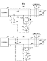
図2(A)は、充電器100の負極側充電用ライン103Bで地絡が発生した場合の地絡電流の流れを示す図であり、図2(B)は、充電器100の正極側充電用ライン103Aで地絡が発生した場合の地絡電流の流れを示す図である。なお、これらの図においては、地絡電流が流れる閉回路部分の構成のみが示され、それ以外の構成は省略されている。
充電器100の接触式コネクタ101を電気自動車200側の接触式コネクタ201に装着することによって、充電器100の正極側および負極側充電用ライン103A,103Bの端子を電気自動車200の正極側および負極側充電用ライン206A,206Bの端子にそれぞれ接続し、充電器100から電気自動車200の車載バッテリ202に直流電流I1を供給すると(図1参照)、電気自動車200の車載バッテリ202の急速充電が開始する。この状態においては、抵抗値の等しい2つの抵抗1021A,1021Bにかかる電圧がバランスしているため、接地接続ポイント1021Cとアース400とが同電位(0V)となり、接地線1023に直流電流は流れない。
ここで、図2(A)に示すように、充電器100の負極側充電用ライン103Bの任意の位置(地絡点)P1で地絡が発生すると、アース400から負極側充電用ライン103Bの地絡点P1に流れ込んだ地絡電流I2は、交直変換部103、正極側充電用ライン103A、一方の抵抗1021Aおよび接地線1023を介してアース400に流れ込む。このため、電流検出器1022は、この地絡電流I2を検知する。
一方、図2(B)に示すように、充電器100の正極側充電用ライン103Aの任意の位置(地絡点)P2で地絡が発生すると、正極側充電用ライン103Aの地絡点P2からアース400に流れ込んだ地絡電流I3は、接地線1023、他方の抵抗1021Bおよび負極側充電用ライン103Bを介して交直変換部103に流れ込む。このため、電流検出器1022は、この地絡電流I3を検知する。
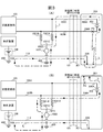
図3(A)は、電気自動車200の負極側充電用ライン206Bで漏電が発生した場合の漏洩電流の流れを示す図であり、図3(B)は、電気自動車200の正極側充電用ライン206Aで漏電が発生した場合の漏洩電流の流れを示す図である。なお、これらの図においては、漏洩電流が流れる閉回路部分の構成のみが示され、それ以外の構成は省略されている。
前述したように、電気自動車200の車載バッテリ202の急速充電が正常に行われている間、地絡検出装置102においては、抵抗値の等しい2つの抵抗1021A,1021Bにかかる電圧がバランスしているため、接地線1023に直流電流は流れない。
ここで、図3(A)に示すように、電気自動車200の負極側充電用ライン206Bの任意の位置(漏電点)P3で漏電が発生すると、車体アース203から負極側充電用ライン206Bの漏電点P3に流れ込む漏洩電流I4は、正極側充電用ライン206A、充電器100の正極側充電用ライン103A、地絡検出装置102の一方の抵抗1021Aおよび接地線1023を介してアース400に流れ込み、さらに、制御系電源108の接地線109と通信用アース線110,205とを介して車体アース203に戻る。すなわち、本来、制御装置104の電源グラウンドはアース400と共用されていないものであるところ、本実施の形態においては、制御系電源108の一方の極をアース400に接地する接地線109を設けて、制御装置104の電源グラウンドと、地絡検出装置102が接続されたアース400とを共用化したことにより、電気自動車200側で発生した漏洩電流I4が、地絡検出装置102の接地線1023、制御系バッテリ108の接地線109および通信用アース線110,205を経由するルートが形成される。このため、地絡検出装置102の電流検出器1022は、この漏洩電流I4を検知する。
一方、図3(B)に示すように、電気自動車200の正極側充電用ライン206Aの任意の位置(漏電点)P4で漏電が発生すると、正極側充電用ライン206Aの漏電点P4から車体アース203に流れ込んだ漏洩電流I5は、通信用アース線205,110と制御系電源108の接地線109とを介して充電器100のアース400に流れ込み、さらに、地絡検出装置102の他方の抵抗1021Bおよび充電器100の負極側充電用ライン103Bを介して車体アース203に戻る。すなわち、本来、制御装置104の電源グラウンドはアース400と共用されていないものであるところ、本実施の形態においては、上述したように接地線109を設けて、制御装置104の電源グラウンドと、地絡検出装置102が接続されたアース400とを共用化したことにより、電気自動車200側で発生した漏洩電流I5が、通信用アース線110,205、制御系バッテリ108の接地線109および地絡検出装置102の接地線1023を経由するルートが形成される。このため、地絡検出装置102の電流検出器1022は、この漏洩電流I5を検知する。
以上からわかるように、電気自動車200の車載バッテリ202への急速充電中に、充電器100の正極側および負極側のいずれかの充電用ライン103A,103Bにおける地絡発生だけでなく、電気自動車200の正極側および負極側のいずれかの充電用ライン206A,206Bにおける漏電発生も、電流検出器1022の測定値から検出することができる。
そこで、本実施の形態において、充電器100において、制御器1024は、電気自動車200の車載バッテリ202への急速充電中、電流検出器1022から逐次入力される測定値を監視し、その測定値が、あらかじめ定めた閾値を超えると、充電器100側の地絡または電気自動車200側の漏電が発生したと判断して、地絡発生を示す異常信号を制御装置104に送信する。これに応じて、制御装置104は、漏電遮断器105の制御により電源回路を遮断させる。
ところで、例えば車載バッテリ202の電池セル列の中央(車載バッテリ202の両端子からの電位差が等しくなる位置)付近において車体アース203(=アース400)への漏電が発生した場合、抵抗値の等しい2つの抵抗1021A,1021Bにかかる電圧がバランスし、いずれの抵抗1021A,1021Bにも、電気自動車200側で発生した漏洩電流が流れない可能性が考慮される。本実施の形態においては、このような場合においても、確実に電源回路を遮断することができるように、電気自動車200側では、車載バッテリ202への急速充電中も車載バッテリ202の監視を継続しており、車載バッテリ202に異常が発生したときには、車載バッテリ202の異常発生を充電器100に通知している。このため、充電器100側において電源回路を確実に遮断することができる。
つぎに、本実施形態に係る充電システムによる充電処理について説明する。
図4は、本実施形態に係る充電処理のフローチャートである。
駐車中の電気自動車200の接触式コネクタ201に充電器100の接触式コネクタ101が装着されると、充電器100の制御装置104は、電気自動車200側における漏電発生の有無に関する通知を待つ(S550)。
このとき、電気自動車200の制御装置204は、絶縁監視装置210(交流電流検出器213)からの出力の演算処理(高速フーリエ変換等)を実行して、現在における地絡等の発生の有無を判断し、その判断結果を、通信路を介して充電器100に通知する(S500)。
充電器100の制御装置104は、電気自動車200側の漏電発生の有無に関する通知を受け付けると、この通知が、電気自動車200側で漏電が発生したことを示していれば(S550でYes)、例えば、電気自動車200の車載バッテリ202への供電が行われない旨のメッセージの出力等を行い、処理を終了する。
一方、電気自動車200からの通知が、電気自動車200側で漏電発生がないことを示していれば(S550でNo)、充電器100の制御装置104は、絶縁監視停止指示を、通信路を介して電気自動車200に送信する(S551)。なお、電気自動車200が自律的に絶縁監視を停止できる場合、例えば、電気自動車200が充電開始に先立って漏洩発生の有無を判断し、漏洩が発生していないことを確認して絶縁監視を停止した場合、充電器100は、電気自動車200に絶縁監視停止指示を送信しなくてもよい。
電気自動車200の制御装置204は、この絶縁監視停止指示を受け付けると、絶縁監視装置210(交流電流検出器213)からの出力の演算処理(高速フーリエ変換等)を停止する(S501)。あるいは、交流電圧発生装置212による交流電圧の発生を停止するようにしてもよい。これにより、電気自動車200側における絶縁監視が一時的に停止する。ただし、バッテリ監視部209による車載バッテリ202の状態監視は、その後も継続的に実行される。
その後、充電器100の制御装置104は、地絡検出装置102の出力(電流検出器1022の実測電流値)と閾値との比較処理による地絡等の監視、すなわち、充電器100側における地絡発生および電気自動車200側における漏電発生の双方の監視を開始する(S552)。そして、接触式コネクタ101のロック等の所定の充電開始動作を行ってから、直交変換部103からの供電を開始する(S553)。これにより、以後、電気自動車200の車載バッテリ202への急速充電が行われる。
その後、電気自動車200側では、バッテリ監視部209が、車載バッテリ202の状態の常時監視中に、車載バッテリ202の状態が所定の異常条件を満たしたと判断すると(S502でYes)、その旨を制御装置204に通知する。ここで、車載バッテリ202の異常状態を検知するための異常条件として、車載バッテリ202が、例えば、いずれかの電池セルの温度が所定値以上に上昇した状態、および、いずれかの電池セルの端子間電圧が所定値以下に低下した状態の少なくとも一方の状態にあることなどを用いることができる。そして、車載バッテリ202の異常状態を示す通知を受け付けた制御装置204は、車載バッテリ202の異常発生を、通信路を介して充電器100に通知し(S503)、さらに、絶縁監視装置210(交流電流検出器213)からの出力の演算処理(高速フーリエ変換等)を再開する(S505)。これにより、電気自動車200側における絶縁監視が再開し、以後、電気自動車200側で漏電が発生したときには、制御装置204が所定の漏電時対応処理を実施する。
一方、充電器100側では、制御器1024が、電流検出器1022の出力と閾値との比較処理による地絡等の監視中に、充電器100側における地絡または電気自動車200側における漏電が発生したと判断すると(S554でYes)、地絡等の発生を示す異常信号を制御装置104に送信する。これに応じて、制御装置104は、漏電遮断器105を制御して電源回路を遮断させる(S558)。そして、充電器100側における地絡発生または電気自動車200側における漏電発生を通知するメッセージを、通信路を介して電気自動車200の制御装置204に送信する。なお、充電器100が出力装置を有する場合には、このとき、制御装置204が、管理者等への通報を出力装置から出力するようにしてもよい。
また、車載バッテリ202の異常発生の通知を電気自動車200から受け付けた場合にも(S555でYes)、制御装置104は、漏電遮断器105の制御により電源回路を遮断させる(S558)。
さて、電気自動車200の車載バッテリ202の充電が正常に完了した場合(S556でYes、S504でYes)、充電器100側では、制御装置104が、交直変換部103による供電を停止し、接触式コネクタ101のロック解除等の所定の充電終了動作を行う(S557)。また、電気自動車200側では、絶縁監視装置210(交流電流検出器213)からの出力の演算処理(高速フーリエ変換等)を再開し(S505)、以後、電気自動車200側で漏電が発生したときには、制御装置204が所定の漏電時対応処理を実施する。
以上、本発明の実施の形態について説明した。
本実施の形態によれば、電気自動車200の急速充電中において、充電器100側における地絡発生時には、地絡検出装置102の電流検出器1022が0.1~数mA程度の直流電流を検出するため、この実測値をそのまま閾値と比較することにより、地絡発生を直ちに検出可能である。
また、電気自動車200の制御装置204と充電器100の制御装置104との基準電位共通化のための既存の通信用アース線110を接地線109で充電器100側のアース400に接地したことにより、電気自動車200側で発生した漏洩電流I4,I5が、地絡検出装置102の電流検出器1022を介して電気自動車200側に戻るループが形成されるため、急速充電中の電気自動車200における漏電発生も、地絡検出装置102の電流検出器1022の実測値と閾値との比較により直ちに検出することができる。このため、FFT等といった、ある程度の時間を要する演算処理を行う必要がなく、その分、より迅速に充電器100側の地絡および電気自動車200側の漏電の双方を検出することができる。これにより、電源回路の遮断までに要する時間をより短縮できる。また、充電器100側で、より確実に電源回路を遮断することができる。
ここで、車載バッテリ202の電池セル列の中央(車載バッテリ202の両端子からの電位差が等しくなる位置)付近で車体アース203(=アース400)への漏電が発生した場合、いずれの抵抗1021A,1021Bにも電気自動車200側の漏洩電流が流れない可能性が考慮される。しかし、本実施の形態においては、電気自動車200側において、車載バッテリ202の急速充電中も車載バッテリ202の監視を継続しており、急速充電中の車載バッテリ202に異常が発生したときには、車載バッテリ202の異常発生を充電器100に通知している。このため、充電器100側において、電源回路を確実に遮断することができる。
したがって、本実施の形態によれば、電気自動車200の急速充電中における充電器100の地絡および電気自動車200の漏電をより迅速に検出でき、供電回路を確実に遮断することができる。
また、充電器100の正極側および負極側充電用ライン103A,103Bに、交直変換部103内部で発生したノイズをアース400にバイパスさせるためのノイズ除去用コンデンサが設けられている場合、仮に従来のコンデンサ型の絶縁監視装置を充電器100の地絡検出装置としてそのまま適用すると、地絡検出装置が発生する交流電流が地絡検出装置のコンデンサとノイズ除去用コンデンサとを循環してしまう可能性がある。このような交流電流の循環が発生すると、実際には漏電が発生していないにも関わらず、漏電が誤検知される可能性がある。しかし、本実施の形態に係る地絡検出装置102には、充電器100のノイズ除去用コンデンサと干渉する要素が含まれていないため、充電器100の他の要素との干渉に起因する地絡誤検出の発生を防止することができる。したがって、地絡検出の信頼性が向上する。
また、電気自動車200の急速充電中、充電器100側における地絡発生だけでなく、電気自動車200側における漏電発生も1台の電流検出器1022の測定値に基づき検知することができるため、より安価な充電器100を実現することができる。
なお、本実施の形態では、接地接続ポイント1021C-アース400間の直流電流を電流検出器1022で検出しているが、接地接続ポイント1021C-アース400間の電圧を電圧検出器で検出してもよい(以下においても同様)。この場合、接地線1023は、少なくとも、接地接続ポイント1021C-アース400間の電圧を検出するのに十分な抵抗を有している必要がある。
また、以上においては、電流検出器1022の測定値に基づき地絡発生を判断する制御器1024を地絡検出装置102内に設けているが、例えば、制御装置104が、電流検出器1022の測定値の入力を逐次受け付け、この測定値と閾値との比較により地絡発生を判断するようにしてもよい(以下においても同様)。
ところで、本実施の形態では、電気自動車200の制御装置204と充電器100の制御装置104との基準電位共通化のための通信用アース線110が充電器100のアース400に接地されている。このため、充電器100の制御装置104へのサージ等の影響を考慮する必要が生じるケースがある。以下、サージ対策が施された電気自動車用充電器の構成について、前述の充電器100との相違点を中心に説明する。
図5は、サージ対策を施した充電器100Aの概略構成を説明するための図である。なお、図5において、前述の充電器100と同様の構成については、図1と同じ符号が付してある。
図示するように、充電器100Aの制御装置104Aは、充電器100A全体の制御処理を実行する制御系回路部1042と、電気自動車200とのデータ通信処理を実行する通信系回路部1041と、制御系回路部1042のデータ転送線および通信系回路部1041のデータ転送線をつなぐフォトカプラ1043と、を有する。すなわち、制御装置104A内部において、制御系回路部1042と通信系回路部1041とが、相互のデータ通信を非接触(電気的に分離された状態)で実現している。
充電器100Aは、接地線109および通信用アース線110の双方に負極がつながれた前述の制御系電源108とは独立して、アース400から浮いた別の制御系電源108Aをさらに備えている。そして、前述の制御系電源108は通信系回路部1041に12V電源を供給し、制御系電源108Aは制御系回路部1042に12V電源を供給している。その他の構成は、前述の充電器100と同様である。
このような構成によれば、制御系回路部1042と電気自動車200の制御装置204との間のデータ通信を可能としつつ、制御系回路部1042をアース400から浮かすことができる。このため、前述の充電器100と同様、地絡検出装置102は、急速充電中の充電器100Aにおける地絡発生を検知するだけでなく、急速充電中の電気自動車200における漏電発生も、通信用アース線110,205および接地線109を利用して検知できる。これに加えて、充電器100の制御装置104へのサージ等の影響を防止することができる。
なお、ここでは、制御系回路部1042のデータ転送線と通信系回路部1041のデータ転送線と間をフォトカプラ1043でつないでいるが、制御系回路部1042と通信系回路部1041との間のデータ転送を非接触で実現できるもので両者をつなぐものであればよい。例えば、制御系回路部1042のデータ転送線と通信系回路部1041のデータ転送線と間を非接触型のリレーでつないでもよい。
また、本発明は、電気自動車のみならず、搭載されたバッテリの外部電源からの充電機能を有する電動車両に広く適用できる。
電動車両への充電中に、充電器側において、充電器における地絡発生および電動車両における漏電発生の双方を迅速に検知し、より確実に遮断可能とする技術のひとつとして適用可能である。
100,100A:充電器、101:接触式コネクタ、102:地絡検出装置、103:交直変換部、103A:正極側充電用ライン、103B:負極側充電用ライン、104,104A:制御装置、105:漏電遮断器(ELB)、106:充電ケーブル、107:通信用ライン、108,108A:制御系電源、109:接地線、110:通信用アース線、200:電気自動車、201:接触式コネクタ、202:車載バッテリ、203:車体アース、204:制御装置、205:通信用アース線、206A:正極側充電用ライン、206B:負極側充電用ライン、207:通信用ライン、208:制御系電源、209:バッテリ監視部、210:絶縁監視装置、211:コンデンサ、212:交流電圧発生器、213:交流電流検出器、300:交流電源、400:アース、1021A,1021B:抵抗、1021:抵抗の直列回路、1023:接地線、1022:電流検出器、1024:制御器、1041:通信系回路部、1042:制御系回路部、1043:フォトカプラ
Claims (7)
- 車載バッテリを搭載した電動車両と、前記車載バッテリへの充電中、制御装置に電源供給する第一の電源の負極が通信用アース線により前記電気自動車の車体アースにつながれて前記電動車両と前記制御装置とのデータ通信を実現する充電器と、を備える充電システムであって、
前記充電器は、
前記車載バッテリに供電するための正極側および負極側充電用ラインと、
前記正極側および負極側充電用ライン間に挿入された、抵抗値の等しい2つの抵抗からなる直列回路と、
前記2つの抵抗間に定めた接地位置をアースにつなぐ第一の接地線と、
前記通信用アース線を前記アースにつなぐ第二の接地線と、
前記第一の接地線に流れる電流、または前記接地位置および前記アース間の電圧を検出する検出手段と、
前記制御装置の指示に従い前記車載バッテリへの供電を遮断する遮断器と、を備え、
前記電動車両は、
前記車載バッテリの状態を監視するバッテリ監視手段と、
前記車載バッテリの充電中に前記バッテリ監視手段が前記車載バッテリの異常を検出した場合、前記車載バッテリの異常発生を前記充電器に通知する通知手段と、を備え、
前記制御装置は、
前記正極側および負極側のいずれかの充電用ラインにおける地絡または前記電動車両における漏電の有無を前記検出手段の検出値に基づき判断し、
前記地絡または前記漏電の発生を検出した場合、および前記電動車両から前記車載バッテリの異常発生を通知された場合、前記遮断器に、前記車載バッテリへの供電の遮断を指示する
ことを特徴とする充電システム。 - 車載バッテリを搭載した電動車両と、前記車載バッテリへの充電中、制御装置に電源供給する第一の電源の負極が通信用アース線により前記電気自動車の車体アースにつながれて前記電動車両と前記制御装置とのデータ通信を実現する充電器と、を備える充電システムであって、
前記充電器は、
前記車載バッテリに供電するための正極側および負極側充電用ラインと、
前記正極側および負極側充電用ライン間に挿入された、抵抗値の等しい2つの抵抗からなる直列回路と、
前記2つの抵抗間に定めた接地位置をアースにつなぐ第一の接地線と、
前記通信用アース線を前記アースにつなぐ第二の接地線と、
前記第一の接地線に流れる電流、または前記接地位置および前記アース間の電圧を検出する検出手段と、
前記検出手段の検出値に基づき、前記正極側および負極側のいずれかの充電用ラインにおける地絡または前記電動車両における漏電の有無を判断する制御器と、
前記制御装置の指示に従い前記車載バッテリへの供電を遮断する遮断器と、を備え、
前記電動車両は、
前記車載バッテリの状態を監視するバッテリ監視手段と、
前記車載バッテリの充電中に前記バッテリ監視手段が前記車載バッテリの異常を検出した場合、前記車載バッテリの異常発生を前記充電器に通知する通知手段と、を備え、
前記制御装置は、
前記制御器が前記地絡または前記漏電の発生を検出した場合、および前記電動車両から前記車載バッテリの異常発生を通知された場合、前記遮断器に、前記制御装置の指示に従い前記車載バッテリへの供電の遮断を指示する
ことを特徴とする充電システム。 - 請求項1に記載の充電システムであって、
前記電気自動車用充電器は、
前記アースから絶縁された第二の電源をさらに備え、
前記制御装置は、
前記第一の電源から電源供給され、前記電気自動車との間のデータ通信を実行する通信系回路部と、
前記第二の電源から電源供給され、当該充電器の制御処理を実行する制御系回路部と、
前記制御系回路部および前記通信系回路部間のデータ転送を非接触で行う中継装置と、を備える
ことを特徴とする充電システム。 - 請求項2に記載の充電システムであって、
前記電気自動車用充電器は、
前記アースから絶縁された第二の電源をさらに備え、
前記制御装置は、
前記第一の電源から電源供給され、前記電気自動車との間のデータ通信を実行する通信系回路部と、
前記第二の電源から電源供給され、当該充電器の制御処理を実行する制御系回路部と、
前記制御系回路部および前記通信系回路部間のデータ転送を非接触で行う中継装置と、を備える
ことを特徴とする充電システム。 - 請求項1ないし4のいずれか1項に記載の充電器。
- 請求項1ないし4のいずれか1項に記載の電動車両。
- 制御装置に電源供給する電源の負極が通信用アース線で充電対象の電動車両の車体アースにつながれて前記電動車両と前記制御装置とのデータ通信を実現する充電器により、前記電動車両の車載バッテリに充電する充電方法であって、
前記車載バッテリへ供電するための正極側および負極側充電用ライン間には、抵抗値の等しい2つの抵抗からなる直列回路が挿入され、前記2つの抵抗間に定めた接地位置と前記通信用アース線とがそれぞれアースにつながれており、
前記車載バッテリの充電中、前記充電器において、前記接地位置と前記アースとの間を流れる電流、または前記接地位置と前記アースとの間の電圧が検出手段で逐次測定され、前記制御装置または前記制御装置とは別に前記電動車両用充電器に設けられた制御器は、前記検出手段の測定値に基づき前記地絡および前記漏電の有無を判断しており、前記制御装置は、前記正極側および負極側のいずれかの充電用ラインにおける地絡または前記電動車両における漏電が発生した場合、および前記電動車両からバッテリ異常発生通知を受信した場合、遮断器に、前記車載バッテリへの供電の遮断を指示し、
前記車載バッテリの充電中、前記電動車両において、前記車載バッテリの状態がバッテリ監視手段で監視されており、前記バッテリ監視手段が前記車載バッテリの異常を検出した場合、通信手段が前記バッテリ異常発生通知を前記充電器に送信する
ことを特徴とする地絡検出方法。
Applications Claiming Priority (2)
| Application Number | Priority Date | Filing Date | Title |
|---|---|---|---|
| JP2009088254A JP2010239845A (ja) | 2009-03-31 | 2009-03-31 | 充電システム、電動車両の充電方法、および電動車両 |
| JP2009-088254 | 2009-03-31 |
Publications (1)
| Publication Number | Publication Date |
|---|---|
| WO2010113936A1 true WO2010113936A1 (ja) | 2010-10-07 |
Family
ID=42828226
Family Applications (1)
| Application Number | Title | Priority Date | Filing Date |
|---|---|---|---|
| PCT/JP2010/055669 Ceased WO2010113936A1 (ja) | 2009-03-31 | 2010-03-30 | 充電システム、電動車両の充電方法、および電動車両 |
Country Status (2)
| Country | Link |
|---|---|
| JP (1) | JP2010239845A (ja) |
| WO (1) | WO2010113936A1 (ja) |
Cited By (10)
| Publication number | Priority date | Publication date | Assignee | Title |
|---|---|---|---|---|
| WO2012156635A1 (fr) * | 2011-05-19 | 2012-11-22 | Renault S.A.S. | Dispositif et procede d'estimation de la resistance du raccordement a la terre d'un appareil electrique |
| WO2014095574A1 (fr) * | 2012-12-20 | 2014-06-26 | Renault S.A.S. | Procede de commande d'un chargeur de batterie de vehicule automobile et chargeur associe |
| CN103988087A (zh) * | 2011-12-26 | 2014-08-13 | 川崎重工业株式会社 | 漏电检测器、电动式交通工具的漏电检测方法 |
| WO2014156131A1 (ja) * | 2013-03-28 | 2014-10-02 | パナソニック株式会社 | 電動車両用コネクタおよび車両用電力装置 |
| US20140347769A1 (en) * | 2011-10-03 | 2014-11-27 | Panasonic Corporation | Electric-vehicular charge and discharge device |
| CN108367681A (zh) * | 2015-12-18 | 2018-08-03 | 裕罗有限公司 | 电动汽车充电线控制装置的自动重合装置及方法 |
| WO2023007253A1 (en) * | 2021-07-30 | 2023-02-02 | Abb Schweiz Ag | Forced symmetry insulation monitoring device and method |
| CN116203458A (zh) * | 2021-11-30 | 2023-06-02 | 比亚迪股份有限公司 | 车辆及其漏电检测定位方法 |
| FR3142304A1 (fr) * | 2022-11-23 | 2024-05-24 | Psa Automobiles Sa | Procede de surveillance d’une commande d’arret de charge pour un vehicule electrifie |
| WO2024224223A1 (en) * | 2023-04-27 | 2024-10-31 | H55 Sa | Insulation fault detection device, electrical power supply system, and a method for detecting an insulation fault |
Families Citing this family (16)
| Publication number | Priority date | Publication date | Assignee | Title |
|---|---|---|---|---|
| JP5887528B2 (ja) * | 2011-08-11 | 2016-03-16 | パナソニックIpマネジメント株式会社 | 電気車両用充電装置 |
| WO2013105477A1 (ja) | 2012-01-10 | 2013-07-18 | 住友電気工業株式会社 | 受電コネクタ及び通信システム |
| JP5426698B2 (ja) | 2012-01-10 | 2014-02-26 | 住友電気工業株式会社 | 受電コネクタ、充電システム及び通信システム |
| JP5577379B2 (ja) * | 2012-05-21 | 2014-08-20 | 株式会社日本自動車部品総合研究所 | 充電装置 |
| JP6308486B2 (ja) | 2012-09-13 | 2018-04-11 | パナソニックIpマネジメント株式会社 | リレー溶着検出装置 |
| JP6219619B2 (ja) * | 2013-06-24 | 2017-10-25 | 株式会社ダイヘン | 充電システム |
| JP6020388B2 (ja) * | 2013-08-22 | 2016-11-02 | 株式会社デンソー | 電力供給装置 |
| US10725115B2 (en) * | 2014-10-16 | 2020-07-28 | Ford Global Technologies, Llc | Methods and apparatus for detecting electrical leakage in a vehicle |
| JP6112517B2 (ja) * | 2015-07-23 | 2017-04-12 | 三菱電機株式会社 | 電力変換装置、電源切替装置、住宅及び電力変換方法 |
| JP6515895B2 (ja) * | 2016-08-30 | 2019-05-22 | トヨタ自動車株式会社 | 充電システムおよび電動車両 |
| JP7049206B2 (ja) | 2018-07-24 | 2022-04-06 | 株式会社ダイヘン | 非接触給電装置 |
| CN110492575B (zh) * | 2019-09-05 | 2021-11-16 | 深圳传音控股股份有限公司 | 用于手持设备的快速充电系统及方法、手持设备 |
| CN112373307A (zh) * | 2020-11-18 | 2021-02-19 | 北京现代汽车有限公司 | 充电保护方法、系统和车辆 |
| KR102295910B1 (ko) * | 2021-04-15 | 2021-08-31 | 주식회사 한우리이엔지 | 감전사고 방지기능을 가지는 전기차 충전시스템 |
| DE102022002596A1 (de) * | 2022-07-18 | 2024-01-18 | Mercedes-Benz Group AG | Fahrzeug mit einem Hochvoltbordnetz und Verfahren zum Betrieb des Hochvoltbordnetzes |
| EP4733117A1 (en) * | 2024-10-24 | 2026-04-29 | Watt & Well | A supply equipment communication controller module in a charging station for batteries |
Citations (4)
| Publication number | Priority date | Publication date | Assignee | Title |
|---|---|---|---|---|
| JPS549838U (ja) * | 1977-06-24 | 1979-01-23 | ||
| JPS57119263A (en) * | 1981-01-17 | 1982-07-24 | Fuji Electric Co Ltd | Detecting method for leak in dc power source |
| JPH07123599A (ja) * | 1993-10-18 | 1995-05-12 | Toyota Motor Corp | 充電制御装置 |
| JP2000354332A (ja) * | 1999-06-09 | 2000-12-19 | Matsushita Electric Works Ltd | 電気自動車用充電装置 |
-
2009
- 2009-03-31 JP JP2009088254A patent/JP2010239845A/ja active Pending
-
2010
- 2010-03-30 WO PCT/JP2010/055669 patent/WO2010113936A1/ja not_active Ceased
Patent Citations (4)
| Publication number | Priority date | Publication date | Assignee | Title |
|---|---|---|---|---|
| JPS549838U (ja) * | 1977-06-24 | 1979-01-23 | ||
| JPS57119263A (en) * | 1981-01-17 | 1982-07-24 | Fuji Electric Co Ltd | Detecting method for leak in dc power source |
| JPH07123599A (ja) * | 1993-10-18 | 1995-05-12 | Toyota Motor Corp | 充電制御装置 |
| JP2000354332A (ja) * | 1999-06-09 | 2000-12-19 | Matsushita Electric Works Ltd | 電気自動車用充電装置 |
Cited By (17)
| Publication number | Priority date | Publication date | Assignee | Title |
|---|---|---|---|---|
| FR2975498A1 (fr) * | 2011-05-19 | 2012-11-23 | Renault Sa | Dispositif et procede d'estimation de la resistance du raccordement a la terre d'un appareil electrique |
| WO2012156635A1 (fr) * | 2011-05-19 | 2012-11-22 | Renault S.A.S. | Dispositif et procede d'estimation de la resistance du raccordement a la terre d'un appareil electrique |
| US20140347769A1 (en) * | 2011-10-03 | 2014-11-27 | Panasonic Corporation | Electric-vehicular charge and discharge device |
| CN103988087A (zh) * | 2011-12-26 | 2014-08-13 | 川崎重工业株式会社 | 漏电检测器、电动式交通工具的漏电检测方法 |
| CN103988087B (zh) * | 2011-12-26 | 2016-11-09 | 川崎重工业株式会社 | 漏电检测器、电动式交通工具的漏电检测方法 |
| WO2014095574A1 (fr) * | 2012-12-20 | 2014-06-26 | Renault S.A.S. | Procede de commande d'un chargeur de batterie de vehicule automobile et chargeur associe |
| FR3000315A1 (fr) * | 2012-12-20 | 2014-06-27 | Renault Sa | Procede de commande d'un chargeur de batterie de vehicule automobile et chargeur associe. |
| US20160052411A1 (en) * | 2013-03-28 | 2016-02-25 | Panasonic Intellectual Property Management Co., Ltd. | Electric vehicular connector and vehicular power supply device |
| JP2014195340A (ja) * | 2013-03-28 | 2014-10-09 | Panasonic Corp | 車両用電力装置 |
| WO2014156131A1 (ja) * | 2013-03-28 | 2014-10-02 | パナソニック株式会社 | 電動車両用コネクタおよび車両用電力装置 |
| US9821669B2 (en) | 2013-03-28 | 2017-11-21 | Panasonic Intellectual Property Management Co., Ltd. | Electric vehicular connector and vehicular power supply device |
| CN108367681A (zh) * | 2015-12-18 | 2018-08-03 | 裕罗有限公司 | 电动汽车充电线控制装置的自动重合装置及方法 |
| US11230194B2 (en) | 2015-12-18 | 2022-01-25 | Yura Corporation Co., Ltd. | Automatic reclosing device and method for electrical vehicle charging cable control device |
| WO2023007253A1 (en) * | 2021-07-30 | 2023-02-02 | Abb Schweiz Ag | Forced symmetry insulation monitoring device and method |
| CN116203458A (zh) * | 2021-11-30 | 2023-06-02 | 比亚迪股份有限公司 | 车辆及其漏电检测定位方法 |
| FR3142304A1 (fr) * | 2022-11-23 | 2024-05-24 | Psa Automobiles Sa | Procede de surveillance d’une commande d’arret de charge pour un vehicule electrifie |
| WO2024224223A1 (en) * | 2023-04-27 | 2024-10-31 | H55 Sa | Insulation fault detection device, electrical power supply system, and a method for detecting an insulation fault |
Also Published As
| Publication number | Publication date |
|---|---|
| JP2010239845A (ja) | 2010-10-21 |
Similar Documents
| Publication | Publication Date | Title |
|---|---|---|
| JP2010239845A (ja) | 充電システム、電動車両の充電方法、および電動車両 | |
| JP5369833B2 (ja) | 電動車両用充電器および地絡検出方法 | |
| CN105486923B (zh) | 用于电绝缘性测试和诊断的总线泄漏电阻估算 | |
| US10144298B2 (en) | Power supply device of vehicle | |
| KR101473397B1 (ko) | 배터리 팩의 전류센서 이상 진단 장치 및 방법 | |
| JP6394631B2 (ja) | 電源装置 | |
| EP2887080B1 (en) | Power supply apparatus | |
| JP5234282B2 (ja) | バッテリパックの検査装置 | |
| KR20190040464A (ko) | 충전 장치 및 복수의 충전 인터페이스를 가진 차량 | |
| US9472941B2 (en) | Battery module | |
| KR101189582B1 (ko) | 배터리 전압 측정 라인의 단선 검출용 전압 측정 장치 | |
| WO2014103707A1 (ja) | 電動車両を用いた電力供給装置 | |
| JP6706688B2 (ja) | 電池制御装置 | |
| JP2010239773A (ja) | 充電器、電動車両、および、充電システムにおける地絡・短絡の検知方法 | |
| US12187163B2 (en) | High-voltage system for a fuel-cell vehicle for determining an insulation fault | |
| US9656569B2 (en) | Vehicle power source apparatus | |
| US10840562B2 (en) | Energy storage system, monitoring unit for energy storage device, and method of monitoring energy storage device | |
| US20170001533A1 (en) | Charging and discharging system for an electric vehicle | |
| JP5104520B2 (ja) | 電動車両の充電装置 | |
| US20140292346A1 (en) | Method and device for monitoring a high-voltage arrangement | |
| WO2010113917A1 (ja) | 地絡検出装置、電動車両用充電器、および地絡検出方法 | |
| CN111823864B (zh) | 高压互锁检测装置、方法和车辆 | |
| WO2022136434A2 (en) | Method and equipment for monitoring a failure in a high-voltage circuit of a vehicle, and high-voltage circuit system | |
| JP2020046334A (ja) | バッテリ監視装置 | |
| JP2015095990A (ja) | リレーの異常検出方法 |
Legal Events
| Date | Code | Title | Description |
|---|---|---|---|
| 121 | Ep: the epo has been informed by wipo that ep was designated in this application |
Ref document number: 10758707 Country of ref document: EP Kind code of ref document: A1 |
|
| NENP | Non-entry into the national phase |
Ref country code: DE |
|
| 122 | Ep: pct application non-entry in european phase |
Ref document number: 10758707 Country of ref document: EP Kind code of ref document: A1 |