WO2010116799A1 - 船舶用の舵及び船舶 - Google Patents
船舶用の舵及び船舶 Download PDFInfo
- Publication number
- WO2010116799A1 WO2010116799A1 PCT/JP2010/052402 JP2010052402W WO2010116799A1 WO 2010116799 A1 WO2010116799 A1 WO 2010116799A1 JP 2010052402 W JP2010052402 W JP 2010052402W WO 2010116799 A1 WO2010116799 A1 WO 2010116799A1
- Authority
- WO
- WIPO (PCT)
- Prior art keywords
- rudder
- ship
- auxiliary
- vertical
- stern
- Prior art date
- Legal status (The legal status is an assumption and is not a legal conclusion. Google has not performed a legal analysis and makes no representation as to the accuracy of the status listed.)
- Ceased
Links
Images


Classifications
-
- B—PERFORMING OPERATIONS; TRANSPORTING
- B63—SHIPS OR OTHER WATERBORNE VESSELS; RELATED EQUIPMENT
- B63H—MARINE PROPULSION OR STEERING
- B63H25/00—Steering; Slowing-down otherwise than by use of propulsive elements; Dynamic anchoring, i.e. positioning vessels by means of main or auxiliary propulsive elements
- B63H25/06—Steering by rudders
- B63H25/38—Rudders
- B63H25/381—Rudders with flaps
Definitions
- the present invention is a ship navigating on the water, because the overall projected area of the rudder as seen from the side of the hull is small and compact, it can be placed in a narrow stern part, and has high turning performance and course stability. It is related with the rudder and ship for ships which can ensure.
- a propeller or other propulsion device and a rudder are provided at the stern, and during navigation, the ship turns by steering, that is, by steering.
- the turning by this rudder generates a force that changes the direction of the hull at the rear of the hull by generating lift in the rudder because the rudder has a large angle with respect to the flow direction in the wake of the flow immediately after the propeller. By doing so, the hull changes its course.
- the basic cross-sectional shape of the rudder of this ship is a symmetrical streamlined type so as to reduce the resistance of the rudder in water when going straight.
- the front end of the rudder is disposed behind the propeller in order to use the rear flow of the propeller, and therefore is located behind the propeller boss.
- the rear end of the rudder is located in front of the stern end for the purpose of preventing damage due to restriction of the total length of the hull and contact with obstacles.
- the upper end of the rudder is provided so as to be able to turn below the stern, it is usually positioned below the portion where the rudder shaft and the stern intersect.
- the lower end of the rudder is set above the base line (B.L.) in consideration of the range of docking for construction and maintenance inspection and the wake of the propeller.
- the rudder in the case of a conventional single-plate rudder, the rudder must be installed in a limited space at the stern while avoiding interference with the propeller and the hull. It may be difficult to secure the rudder area.
- the rudder may constrain the setting of the main item of the hull, such as the need to increase the distance from the stern perpendicular (AP) to the stern end.
- the vehicle has sufficient turning performance during steering, and travels straight ahead.
- a pushing device such as a hydraulic cylinder is moved inside the rudder main body of the ship, and the pushing device moves in the front-rear direction.
- a variable area rudder having an auxiliary rudder that enters and exits the rear part or the rear part has been proposed.
- the present invention has been made in view of the above-mentioned situation, and the purpose thereof is small and compact because the projected area of the entire outer shape of the rudder viewed from the side of the hull is compact, and can be arranged in a narrow stern part, And it is providing the rudder and ship for ships which can generate
- the ship of the present invention for achieving the above object is the above-mentioned when the rudder provided on the stern is viewed from the stern direction and one or more vertical rudder connected to the rudder axis in a ship that sails on the water.
- the total projected rudder area which is the sum of the projected rudder areas as seen from the side direction of all the hulls of the vertical rudder and the auxiliary rudder, It is formed to be larger than the projected area of the outer shape of the entire rudder viewed from the direction.
- the overall projected shape (profile shape) of the rudder as viewed from the side of the hull is smaller and more compact. can do. Therefore, in the design of the stern, while ensuring the steering performance by the rudder, there are less restrictions due to the arrangement of the rudder, etc., and the degree of freedom in the stern design and the hull type (ship length, width, draft, etc.) The degree of freedom of setting can be increased.
- the distance from the stern perpendicular (AP) to the stern end can be shortened accordingly. Since the total length of a cargo ship is limited depending on the port conditions and the scope of regulations, if the distance from the stern perpendicular (AP) to the stern end can be shortened, the cargo hold and engine room can be changed without changing the overall length. There is an advantage that can be lengthened.
- the rudder profile can be made compact, the rudder height can be reduced. As a result, it is possible to arrange the rudder so that most of the rudder enters the wake of the propeller. This makes it possible to fully utilize the wake of the propeller, and at the time of voyage and low speed navigation, provide a larger rudder force than a conventional single-plate rudder with a projected rudder area viewed from the side of the same hull. Can be generated.
- the projected rudder area viewed from the side direction of the hull of each of the auxiliary rudder is formed as 25% to 150% of the projected rudder area viewed from the side direction of the vertical rudder hull.
- the disadvantages such as an increase in resistance and an increase in weight due to the provision of the auxiliary rudder are larger than the merit due to the increase in the total projected rudder area, which is not practical.
- a valve is provided at the intersection of the vertical rudder and the auxiliary rudder.
- the attachment part of a vertical rudder and a subrudder can be formed with a structurally big intensity
- the propulsion efficiency of the vessel at the time of straight traveling can be improved by the effect of increasing the wake gain of the valve to improve the propulsion efficiency, and the energy saving effect can be exhibited.
- At least one of the vertical rudder and the auxiliary rudder has a cross-sectional shape that generates a propulsive force with respect to the longitudinal direction of the ship when the ship goes straight, a shape having an angle of attack, and a camber.
- propulsive force can be generated when the ship goes straight, but the vertical rudder and auxiliary rudder are larger in size than the fins and can exert a large propulsive force.
- the propulsion performance of the ship at the time can be further improved.
- the longitudinal direction of the lift generated by the vertical rudder and the secondary rudder is obtained, and the energy saving effect is obtained by improving the propulsion performance when the ship is traveling straight.
- an end plate for suppressing outflow of vortex generated on the surface of the auxiliary rudder is provided on the auxiliary rudder.
- the vortex tip vortex can be prevented from flowing out from the rudder surface of the auxiliary rudder, so that the lift generated by the auxiliary rudder can be increased. Therefore, the rudder force and propulsive force generated by the auxiliary rudder when the ship goes straight can be further increased, and the maneuvering performance of the ship and the propulsion performance when going straight can be further improved.
- a ship for achieving the above object is configured to include the rudder for the ship described above.
- the marine vessel can improve the turning performance and the needle-keeping performance of the vessel while the profile shape of the rudder is a compact rudder, and can further improve the propulsion performance when the vessel goes straight.
- the projected area of the outer shape of the entire rudder viewed from the side of the hull is small, compact, can be placed even in a narrow stern part, and the degree of freedom in placing the rudder is In addition, a large rudder force can be generated to ensure high turning performance and course stability.
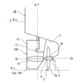
- FIG. 1 is a side view of a stern portion showing a structure of a rudder for a ship and a ship in a first embodiment according to the present invention.
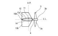
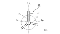
- FIG. 2 is a view from the stern showing the configuration of the rudder for a ship of FIG.
- FIG. 3 is a plan view showing the configuration of the rudder for a ship shown in FIG.
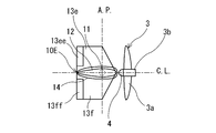
- FIG. 4 is a perspective view showing the configuration of the rudder for a ship shown in FIG. 1 as viewed obliquely from the stern direction toward the bow direction.
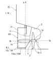
- FIG. 5 is a side view of the stern portion showing the configuration of the boat rudder and the boat according to the second embodiment of the present invention.
- FIG. 6 is a view seen from the stern showing the configuration of the rudder for a ship shown in FIG.
- FIG. 7 is a plan view showing the configuration of the rudder for a ship shown in FIG.
- FIG. 8 is a side view of the stern portion showing the configuration of the boat rudder and the boat according to the third embodiment of the present invention.
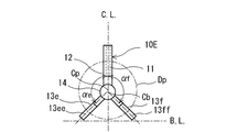
- FIG. 9 is a view seen from the stern showing the configuration of the rudder for a ship of FIG.
- FIG. 10 is a plan view showing the configuration of the boat rudder in FIG.
- FIG. 11 is a view seen from the stern showing another arrangement example (No. 1) of the auxiliary rudder.
- FIG. 12 is a view as seen from the stern showing another arrangement example (No. 2) of the auxiliary rudder.
- FIG. 13 is a view seen from the stern showing another arrangement example (No. 3) of the auxiliary rudder.
- FIG. 14 is a view seen from the stern showing another arrangement example (No. 4) of the auxiliary rudder.
- FIG. 15 is a view seen from the stern showing another arrangement example (No. 5) of the auxiliary rudder.
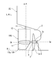
- FIG. 16 is a side view of the stern portion showing the structure of the ship rudder and the ship when the suspension rudder type is adopted.
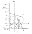
- FIG. 17 is a side view of the stern portion showing the configuration of the boat rudder and the ship when the corner portion on the rear end side of the auxiliary rudder is cut.
- FIG. 1 is a perspective view obliquely viewed from the stern direction to the bow direction.
- FIG. 6 shows the rotation surface of a propeller.
- a ship 1A As shown in FIGS. 1 to 4, a ship 1A according to the first embodiment of the present invention has a propeller 3 attached to a hull 2 at the stern part.
- the propeller 3 is formed by a propeller blade 3 a and a propeller labs 3 b, and is fixed to the propeller rotating shaft 5 by a propeller cap 4.
- a rudder 10A is disposed behind the propeller 3.
- the rudder 10A is fixed to a rudder shaft 11 provided in the vertical direction, and is configured to rotate with the rotation of the rudder shaft 11 by a steering device (not shown).
- the rudder 10A is integrally formed by the vertical rudder 12, one or more (two in FIGS. 1 to 4) auxiliary rudder 13a, 13b, and the valve.
- the cross-sectional shapes of the vertical rudder 12 and auxiliary rudder 13a, 13b are formed as airfoil members.
- the valve 14 is formed as a streamlined substantially rotating member.
- the vertical rudder 12 is a rudder member extending in the vertical direction fixed to the rudder shaft 11, and has substantially the same structure as the rudder of the prior art. However, the vertical rudder 12 may have its lower part removed as shown in FIGS. 1 to 4 due to the attachment of the auxiliary rudder 13a, 13b.
- the shape and size of the vertical rudder 12 takes into consideration the rudder performance when the auxiliary rudder 13a, 13b and the valve 14 are attached, the propulsion performance when traveling straight, the weight of the rudder 10A as a whole, the force required to turn the rudder shaft 11, and the like. Is set.
- the auxiliary rudders 13a and 13b are provided on the vertical rudder 12 connected to the rudder shaft 11 so as to intersect the vertical rudder 12 when viewed from the stern direction. That is, the auxiliary rudders 13a and 13b are attached to the vertical rudder 12 so as to be inclined with the angles ⁇ a and ⁇ b with respect to the vertical rudder 12, that is, the vertical line, as viewed from the stern direction, not the vertical direction.
- the lower ends of the vertical rudder 12 and the auxiliary rudder 13a, 13b are the base line B. L. It is formed so as not to be lower.
- At least one of the vertical rudder 12 and the auxiliary rudder 13a, 13b is arranged with a cross-sectional shape, an angle of attack, and a camber that generate a propulsive force with respect to the longitudinal direction of the ship 1A when the ship 1A goes straight.
- produces with the vertical rudder 12 and the auxiliary rudder 13a, 13b can be obtained, and the propulsion performance of the ship at the time of going straight can be improved.
- the projected rudder area viewed from the side direction of each hull of the auxiliary rudder 13a, 13b is formed as 25% to 150% of the projected rudder area viewed from the side direction of the hull of the vertical rudder 12.
- the disadvantages such as an increase in resistance and an increase in weight due to the provision of the auxiliary rudder 13a and 13b become larger than the merit due to the increase in the total projected rudder area, which is not practical.
- the projected rudder viewed from the side of the hull side of the vertical rudder 12 and the projected rudder viewed from the side of the hull of the auxiliary rudder 13a, 13b rather than the projected area of the outer shape of the rudder 10A as viewed from the side of the hull.
- the total projected rudder area, which is the sum of the areas, is made larger.
- the outer shape (profile shape) of the entire rudder 10A viewed from the side surface of the hull can be made more compact while maintaining the total projected rudder area which is the sum total.
- the lower end of the vertical rudder 12 is connected to the valve.
- the auxiliary rudder 13a, 13b is connected to the valve 14 and extends in the radial direction with the center Cb of the valve 14 as the center. That is, when the rudder 10A provided at the stern is viewed from the stern direction, the vertical rudder 12 and the auxiliary rudder 13a, 13b are integrally provided so as to have a radial shape in three directions.
- the auxiliary rudder 13a, 13b is formed such that its tip is located above the base line of the hull 2.
- auxiliary rudders 13 a and 13 b are provided with inclination angles ⁇ a and ⁇ b with respect to the vertical rudder 12. That is, the lower side has a bifurcated three-pointed arrow shape.
- the plane is symmetrical with respect to the vertical plane including the propeller rotation axis 5.
- the performance can be further improved by forming it asymmetrically in accordance with the propeller wake.
- the corners of the tip of the auxiliary rudder 13a, 13b on the propeller 3 side protrude left and right from the center line of the rudder 10A. Therefore, when turning the rudder 10A, the corner portion is cut so as not to come into contact with the propeller 3. That is, the auxiliary rudder 13a, 13b is formed like a retreating wing to avoid colliding with the propeller 3 when the rudder 10A is rotated left and right.
- valve 14 is provided at the intersection of the vertical rudder 12 and the auxiliary rudder 13a, 13b, in other words, at the connecting portion.
- This valve 14 can give structurally high strength to the attachment portion between the vertical rudder 12 and the sub rudder 13a, 13b.
- there is an effect of increasing the wake gain of the valve by reducing the inflow speed of the flow flowing into the propeller and improving the propulsion efficiency. This effect improves the propulsion performance of the ship 1A when traveling straight, and exhibits an energy saving effect.
- the center Cb of the valve 14 may be coincident with the rotation center Cp of the propeller rotating shaft 5, but the rudder 10A as a whole including the auxiliary rudder 13a and 13b is not necessarily coincided in consideration of the propeller wake. It is preferable to arrange so that the rudder performance is improved.
- the ship 1C is configured to include a rudder 10C.
- the rudder 10C includes an end plate 13cc that suppresses the outflow of vortices generated on the rudder surfaces of the auxiliary rudder 13c and 13d. 13dd is provided at the end of the auxiliary rudder 13c, 13d.
- the other configuration is the same as the rudder 10A of the first embodiment.
- the wing tip vortex is prevented from flowing out from the control surface of the auxiliary rudder 13c and 13d, and the propulsive force generated by the auxiliary rudder 13c and 13d when the ship 1C goes straight can be increased. it can. As a result, the rudder force and the propulsion performance of the ship when traveling straight can be further improved.
- the ship 1E includes a rudder 10E.
- flaps 13ee and 13ff are movably provided at the rear ends of the rudder plates of the auxiliary rudder 13e and 13f.
- the turning force of the rudder 10E around the rudder shaft 11 can be increased and the turning performance of the hull 1E can be improved.
- a flap may be provided only on the vertical rudder 12 instead of the auxiliary rudder 13e, 13f, or a flap may be provided on both the vertical rudder 12 and the auxiliary rudder 13e, 13f.
- FIGS. Some examples of this rudder arrangement are shown in FIGS. However, it is not limited to this. As illustrated in these, the shape of the rudder 10 may be asymmetrical in the vertical direction or asymmetrical in the lateral direction when viewed from the stern. In addition, regarding the shape of the auxiliary rudder 13 as viewed from the stern, a straight line shape facilitates design and work. On the other hand, if it forms in a curve according to the propeller wake, the propeller wake can be used more effectively, and the rudder performance can be further improved.
- the vertical rudder 12 may be formed to extend downward from the position where the auxiliary rudder 13 is attached. Moreover, although not shown in figure, you may provide a fin in any one or some of the vertical rudder 12, the auxiliary rudder 13, and the valve
- FIG. 1 to 10 show examples of arrangements using a rudder with a horn, but depending on the main items of the ship (length, width, draft, etc.), ship speed, rudder size, etc., FIG. A hanging rudder type as shown may be adopted.
- the rudder 10A, 10C, 10E, 10G, 10I and the marine vessels 1A, 1C, 1E, 1G, 1I a plurality of sub rudders 13a, 13b, 13c, 13d, 13e, 13f, 13g,
- the projected area of the outer shape of the rudder 10A, 10C, 10E, 10G, and 10I as viewed from the side of the hull is rectangular.
- the total projected rudder area viewed from the side direction of the hull effective for rudder force can be increased. Therefore, the turning performance and the needle holding performance of the ship can be improved, and the propulsion performance when the ship goes straight can also be improved.
- the rudder 10A, 10C, 10E, 10G, and 10I can realize a rudder force that is almost the same as that of the single plate rudder of the prior art with a smaller projected area viewed from the side of the hull and a compact one. .
- At least one of the vertical rudder 12, the auxiliary rudder 13a, 13b, 13c, 13d, 13e, 13f, 13g, 13h, 13i, and 13j is set in the direction of the captain when the ships 1A, 1C, 1E, 1G, and 1I are traveling straight ahead.
- the auxiliary rudder 13a, 13b, 13c, 13d, 13e, 13f, 13g, 13h, 13i, and 13j is set in the direction of the captain when the ships 1A, 1C, 1E, 1G, and 1I are traveling straight ahead.
- auxiliary rudder 13a, 13b, 13c, 13d, 13e, 13f, 13g, 13h, 13i, and 13j are large in size and can exert a large propulsive force as compared with the fins,
- the propulsion performance of 1A, 1C, 1E, 1G, and 1I can be further improved.
- valve 14 at the intersection of the vertical rudder 12 and the auxiliary rudder 13, the structural strength of the mounting portion between the vertical rudder 12 and the auxiliary rudder 13 can be increased, and the propulsion efficiency can be further improved. it can. Even if the valve 14 is not provided, sufficient structural strength can be ensured, and the valve 14 need not be provided when the propulsion performance based on the effect of increasing the wake gain by the valve 14 is not required.
- the ship of the present invention has a small projected area of the rudder outer shape seen from the lateral direction, and can be disposed in a narrow stern part, and also generates a large rudder force and has high turning performance and course stability. Since it is the rudder and ship for ships which can show the nature, it can be used as a rudder and ship for ships that sail on the water.
Landscapes
- Chemical & Material Sciences (AREA)
- Engineering & Computer Science (AREA)
- Combustion & Propulsion (AREA)
- Mechanical Engineering (AREA)
- Ocean & Marine Engineering (AREA)
- Other Liquid Machine Or Engine Such As Wave Power Use (AREA)
Abstract
水上を航走する船舶1A、1C、1E、1G、1Iにおいて、船尾に設ける舵10A、10C、10E、10G、10Iを、舵軸11に接続する垂直舵12と、1つ以上の、船尾方向から見た場合に前記垂直舵12と交差する副舵13の合体で構成することにより、前記垂直舵12と前記副舵13の全てのそれぞれの船体の側面方向から見た投影舵面積の和である総投影面積を、船体の側面方向から見た舵全体の外形の投影面積よりも大きくして形成する。これにより、船体側面から見た舵全体の外形形状の投影面積を小さく、コンパクトにして、狭い船尾部分にも配置可能にすると共に、大きな舵力を発生して高い旋回性能と針路安定性を確保する。
Description
本発明は、水上を航行する船舶において、船体側面方向から見た舵全体の外形投影面積が小さく、コンパクトであるため、狭い船尾部分に配置することができ、しかも、高い旋回性能と針路安定性を確保することができる船舶用の舵及び船舶に関する。
船舶においては、船尾にプロペラ等の推進器と舵を設けて、航行中に、舵の方向を変える操作、即ち、操舵により旋回している。この舵による旋回は、プロペラの直後の流速の早い後流中で舵が流れ方向に対して大きな角度を持つことにより、舵に揚力を発生させて船体の後部に船体の向きを変える力を発生させることで、船体が変針するものである。
この船舶の舵の基本的な断面形状は、直進時の水中での舵の抵抗を小さくするように、左右対称の流線型となっている。水上を航行する排水量型の船舶においては、この舵の前端は、プロペラの後流れを利用するために、プロペラの後側に配置されるため、プロペラボスよりも後方位置となる。舵の後端は、船体の全長の制限や障害物との接触による損傷を防ぐという理由から船尾端よりも前の位置となる。
また、舵の上端は、船尾より下に旋回可能に設けられる関係から、通常は舵軸と船尾との交差する部位よりも下側の位置となる。また、舵の下端は、建造時や保守点検のためのドック入り時とプロペラ後流の範囲を考慮して、ベースライン(B.L.)より上とされている。
この舵を船舶に装備する際には、所要の操縦性能及び保針性能を確保するために、船の要目(船の長さ、幅、喫水等)によって一定以上の舵面積を確保する必要がある(例えば、非特許文献1、2参照。)。
しかしながら、従来技術の単一板状の舵の場合には、舵はプロペラや船体との干渉を回避して、船尾の限られたスペースに設置しなければならないため、配置上の面から十分な舵面積を確保することが難しい場合が生じる。
そのため、十分な舵面積を確保しようとすると、船尾垂線(A.P.)から船尾端までの距離を大きくする必要が生じるなど、船型要目の設定に舵が制約を与える場合もある。
また、船尾垂線(A.P.)から船尾端までの距離に制約を受けながら、十分な舵面積を確保するためには、舵の縦横比を大きくした縦長の舵形状にすることも考えられるが、その場合には、舵の上部及び下部がプロペラの後流から外れてしまい、舵の効果が十分に得られない。また、当て舵が必要となるという問題が生じ易くなる。
これに関連して、例えば、日本の実開昭63-104199号公報及び日本の実開平01-61000号公報に記載されているように、操舵時には充分な旋回性能を有し、かつ、直進航行時においても舵に働く抵抗が小さくなるという推進性能を向上させるために、船舶の舵本体の内部に、油圧シリンダ等の押圧装置と、この押圧装置により前後方向に移動して、舵本体の前部又は後部に出入する補助舵を備えた可変面積舵が提案されている。
これらの補助舵を出し入れする可変面積舵の場合には、舵本体の機構が複雑となり、補助舵を出し入れできるようにするためには、押圧装置も大規模になるので、工作が難しく、また、高コストである。
森正彦著、「船型設計」、発行所:株式会社船舶技術協会、平成9年2月25日発行、第48頁~第51頁
編集者:関西造船協会、「造船設計便覧(第4版)」、発行所:海文堂出版株式会社、平成8年6月28日発行、第438頁~第441頁
本発明は、上述の状況を鑑みてなされたものであり、その目的は、船体側面方向から見た舵全体の外形形状の投影面積が小さく、コンパクトであるため、狭い船尾部分にも配置でき、しかも、大きな舵力を発生して高い旋回性能と針路安定性を確保することができる船舶用の舵及び船舶を提供することにある。
上記の目的を達成するための本発明の船舶は、水上を航走する船舶において、船尾に設ける舵を、舵軸に接続する垂直舵と、1つ以上の、船尾方向から見た場合に前記垂直舵と交差する副舵の合体で構成することにより、前記垂直舵と前記副舵の全てのそれぞれの船体の側面方向から見た投影舵面積の和である総投影舵面積を、船体の側面方向から見た舵全体の外形の投影面積よりも大きくして形成する。
この構成によれば、船体横方向の舵力を発生させるのに有効な総投影舵面積を大きく維持しながら、船体側面から見た舵全体の外形投影形状(プロファイル形状)はより小さく、コンパクトにすることができる。従って、船尾の設計において、舵による操縦性能を確保しながらも、舵の配置等による制限が少なくなり、船尾の設計における自由度と、船型要目(船の長さ、幅、喫水等)の設定の自由度を増すことができる。
例えば、舵のプロファイル形状を小さくできれば、それに伴って、船尾垂線(A.P.)から船尾端までの距離を短くできる。貨物船では港湾の条件や規則適用の範囲によって全長に制限があるので、船尾垂線(A.P.)から船尾端までの距離を短くできれば、全長を変えずに、その分貨物倉や機関室を長くできるという利点がある。
また、舵のプロファイル形状をコンパクトにできると、舵高さも小さくできる。その結果、舵の大部分がプロペラ後流中に入るように配置することが可能となる。これにより、プロペラ後流を十分に活用して、航海時及び低速航行時においても、同じ船体の側面方向から見た投影舵面積を持つ単一板状の従来技術の舵よりも大きな舵力を発生させることができるようになる。
上記の船舶用の舵において、前記副舵それぞれの船体の側面方向から見た投影舵面積を前記垂直舵の船体の側面方向から見た投影舵面積の25%~150%として形成する。この25%より小さい前記投影舵面積にすると、前記総投影舵面積増加によるメリットよりも、副舵を設けることによる抵抗増加や重量増加等のデメリットが大きくなり実用的ではなくなる。また、150%よりも大きくすると、プロペラ後流から外れる可能性が高く、総投影舵面積が増加しても舵面積の増加の割に舵性能が向上せず、副舵を設けることによる抵抗増加や重量増加等のデメリットが大きくなり実用的ではなくなる。
また、上記の船舶用の舵において、前記垂直舵と前記副舵との交差部にバルブを設ける。この構成によれば、垂直舵と副舵との取り付け部分を構造的に大きな強度を持って形成できる。また、プロペラへ流れ込む流れの流入速度を遅くすることで、推進効率を向上させるというバルブの伴流利得上昇効果により、直進時の船舶の推進性能を向上させ、省エネ効果を発揮することもできる。
また、上記の船舶用の舵において、前記垂直舵と前記副舵の少なくとも1つを、船舶の直進時に、船舶の長手方向に対して推進力を発生する断面形状、迎角及びキャンバーを有する形状として形成する。この構成によれば、舵に付けるフィンと同様に、船舶の直進時に推進力を発生できるが、フィンに比べて垂直舵および副舵はその大きさが大きく、大きな推進力を発揮できるので、直進時の船舶の推進性能をより向上させることができる。即ち、垂直舵と副舵のうち少なくとも1つを、船の長手方向に対して適正な断面形状、迎角、キャンバーを持って配置することで、垂直舵と副舵で発生する揚力の前後方向成分による推進力を得て、船舶の直進時における推進性能の向上による省エネ効果を得る。
また、上記の船舶用の舵において、前記副舵に該副舵の表面で発生した渦の流出を抑制する端板を設ける。この構成によれば、副舵の舵面から翼端渦が流出するのを抑制することができるので、副舵で発生する揚力を大きくすることができる。そのため、船舶の直進時に副舵で発生する舵力及び推進力をより大きくすることができ、船舶の操縦性能及び直進時の推進性能を更に向上させることができる。
そして、上記の目的を達成するための船舶は、上記の船舶用の舵を備えて構成される。この構成により、船舶は、その舵のプロファイル形状がコンパクトな舵でありながら、船舶の旋回性能と保針性能を向上させることができ、更に、船舶直進時の推進性能も向上することができる。
本発明の船舶用の舵及び船舶によれば、船体側面方向から見た舵全体の外形形状の投影面積が小さく、コンパクトで、狭い船尾部分にも配置でき、かつ、舵の配置の自由度が増し、しかも、大きな舵力を発生して高い旋回性能と針路安定性を確保することができる。
以下、図面を参照して本発明に係る実施の形態の船舶用の舵及び船舶について説明する。図1、図5、図8は、船舶の船尾部分と、船舶用の舵の側面図を示し、図2、図6、図9は、船尾方向から舵を見た図を示し、図3、図7、図10は上から舵を見た平面図を示す。また、図4は、船尾方向から船首方向に斜めに見た斜視図を示す。なお、図2、図6、図9の図中のDpはプロペラの回転面を示す。
図1~図4に示すように本発明の第1の実施の形態の船舶1Aは、船尾部分では、船体2にプロペラ3が取り付けられている。このプロペラ3は、プロペラ翼3aとプロペラボス3bとで形成され、プロペラキャップ4により、プロペラ回転軸5に固定されている。このプロペラ3の後方に舵10Aが配置される。この舵10Aは、垂直方向に設けられた舵軸11に固定され、操舵装置(図示しない)による舵軸11の回転に伴って回転するように構成される。
本発明においては、この舵10Aは、垂直舵12と1枚以上(図1~図4では2枚)の副舵13a、13bとバルブ14とで一体に形成される。この垂直舵12と副舵13a、13bの断面形状は翼型部材として形成される。バルブ14は流線型の略回転体状の部材として形成される。
この垂直舵12は、舵軸11に固定される垂直方向に延びる舵部材であり、従来技術の舵と略同じ構造である。しかし、この垂直舵12は、副舵13a、13bを取り付ける関係で、図1~図4に示すようにその下部を削除することもある。この垂直舵12の形状や大きさは、副舵13a、13bとバルブ14を取り付けたときの舵性能や直進時の推進性能、舵10A全体の重量や舵軸11の旋回に要する力等を考慮して設定される。
この副舵13a、13bは、舵軸11に接続する垂直舵12に、船尾方向から見た場合に垂直舵12と交差させて設ける。即ち、副舵13a、13bは、垂直方向ではなく、船尾方向から見て、垂直舵12即ち垂直線に対して、角度αa、αbを有して斜めになるように垂直舵12に取り付ける。また、垂直舵12、副舵13a、13bの下端が船体のベースラインB.L.より下にならないように形成する。
また、垂直舵12とこの副舵13a、13bの少なくとも1つを、船舶1Aの直進時に船舶1Aの長手方向に対して推進力を発生する断面形状、迎角、キャンバーを持って配置する。これにより、垂直舵12と副舵13a、13bで発生する揚力の前後方向成分による推進力を得て、直進時の船舶の推進性能を向上させることができる。
この副舵13a、13bのそれぞれの船体の側面方向から見た投影舵面積を、垂直舵12の船体の側面方向から見た投影舵面積の25%~150%として形成する。この25%より小さい投影舵面積にすると、総投影舵面積増加によるメリットよりも、副舵13a、13bを設けることによる抵抗増加や重量増加等のデメリットが大きくなり実用的ではなくなる。また、150%よりも大きくすると、プロペラ後流から外れる可能性が高く、総投影舵面積が増加しても舵面積の増加の割りに舵性能が向上せず、副舵13a、13bを設けることによる抵抗増加や重量増加等のデメリットが大きくなり実用的ではなくなる。
更に、船体の側面方向から見た舵10A全体の外形の投影面積よりも、垂直舵12の船体の側面方向から見た投影舵面積と副舵13a、13bの船体の側面方向から見た投影舵面積の和である総投影舵面積を大きくして形成する。これにより、この総和である総投影舵面積を大きく維持しながら、船体の側面から見た舵10A全体の外形(プロファイル形状)をよりコンパクトにすることができる。
図1~図4に示す実施の形態の舵10Aでは、垂直舵12はその下端がバルブ14に接続している。また、副舵13a、13bは、バルブ14に接続され、このバルブ14の中心Cbを中心とする放射方向に延びる。つまり、船尾に設ける舵10Aを、船尾方向から見た場合に、3方向の放射状の形状となるように垂直舵12と副舵13a、13bを一体に設けて構成する。この副舵13a、13bは、その先端が、船体2のベースラインより上の位置になるように形成される。
図2に示すように、船尾から見た場合に、垂直舵12に対して傾斜角αa、αbを有して、副舵13a、13bが2つ設けられている。即ち、下側が二股の三ツ矢形状となっている。この図2の例では、設計及び工作が容易であるので、プロペラ回転軸5を含む垂直面に対して面対称に形成されている。しかし、プロペラ後流の流れは必ずしも、プロペラ回転軸5を含む垂直面に対して面対称にならないので、このプロペラ後流に合わせて非対称に形成することで更に性能を向上させることができる。
また、図1の舵10Aの側面図と図3の舵10Aの平面図で分かるように、この副舵13a、13bのプロペラ3側の先端の角部は、舵10Aの中心線から左右に突出するため、舵10Aを旋回したときに、プロペラ3に接触しないように角部をカットする。つまり、副舵13a、13bを後退翼のように形成して、舵10Aを左右に回転したときにプロペラ3に衝突するのを回避する。
また、バルブ14が、垂直舵12と副舵13a、13bとの交差部、言い換えれば、接続部に設けられる。このバルブ14により、垂直舵12と副舵13a、13bとの取り付け部分に構造的に大きな強度を持たせることができる。また、プロペラへ流れ込む流れの流入速度を遅くして、推進効率を向上させるというバルブの伴流利得上昇効果がある。この効果により、直進時の船舶1Aの推進性能が向上し、省エネ効果が発揮される。
なお、このバルブ14の中心Cbはプロペラ回転軸5の回転中心Cpと一致させてもよいが、プロペラ後流を考慮して、必ずしも一致させずに、副舵13a、13bを含めた舵10A全体の舵性能がよくなるように配置することが好ましい。
次に、第2の実施の形態の舵及び船舶について説明する。図5~図7に示すように、この船舶1Cは、舵10Cを備えて構成され、この舵10Cは、副舵13c、13dの舵の表面で発生した渦の流出を抑制する端板13cc、13ddを、副舵13c、13dの端部に設けて構成される。これ以外の構成は第1の実施の形態の舵10Aと同じ構成である。この端板13cc、13ddにより、副舵13c、13dの舵面から翼端渦が流出するのを抑制して、船舶1Cの直進時に副舵13c、13dで発生する推進力をより大きくすることができる。これにより、舵力及び直進時の船舶の推進性能を更に向上させることができる。
次に、第3の実施の形態の舵及び船舶について説明する。図8~図10に示すように、この船舶1Eは、舵10Eを備えて構成される。この舵10Eは、副舵13e、13fの舵板の後端部にフラップ13ee、13ffを可動可能に設ける。このフラップ13ee、13ffにより、舵軸11回りの舵10Eの旋回力を増加させて船体1Eの旋回性能を向上させることができる。なお、副舵13e、13fでなく、垂直舵12のみにフラップを設けてもよく、垂直舵12と副舵13e、13fの両方にフラップを設けてもよい。
また、この舵の配置例を図11~図15に幾つか示す。しかし、これに限定されない。これらに例示するように、舵10の形状は船尾から見たときに、上下非対称でも、左右非対称であってもよい。また、副舵13の船尾から見た形状に関しては、直線形状にすると設計及び工作が容易となる。一方、プロペラ後流に合わせて曲線状に形成すると、プロペラ後流を更に有効利用することができるので、舵の性能をより向上できる。
更に、図12及び図13に示すように、垂直舵12を、副舵13を取り付けた位置よりも下方に延ばして形成してもよい。また、図示しないが、垂直舵12、副舵13、バルブ14の何れか1つ、または、幾つかに、フィンを設けてもよい。
また、図1~図10では、ホーン付きの舵で配置例を示すが、船の要目(船の長さ、幅、喫水等)、船速、舵の大きさなどによっては、図16に示すような吊り舵式が採用される場合もある。
なお、図17に示すように、舵10Iを旋回したときに、副舵13i、13jの後端側が船舶1Iの船尾端6よりも後方に突出することを防ぐ必要がある場合には、副舵13i、13jの後端側の角部をカットする。
上記の船舶用の舵10A、10C、10E、10G、10I、及び、船舶1A、1C、1E、1G、1Iによれば、複数の副舵13a、13b、13c、13d、13e、13f、13g、13h、13i、13jを設けることにより、船体の側面方向から見た舵10A、10C、10E、10G、10I全体の外形形状の投影面積を、従来技術の船体の側面方向から見た形状が長方形や台形などの単一板状の舵と同じとしたときに、舵力に有効な船体の側面方向から見た総投影舵面積を大きくすることができる。従って、船舶の旋回性能と保針性能を向上させることができ、更に、船舶直進時の推進性能も向上することができる。
また、同従来技術の単一板状の舵とほぼ同等の舵力を、舵10A、10C、10E、10G、10Iでは、船体の側面から見た投影面積がより小さくコンパクトなもので、実現できる。
また、垂直舵12、副舵13a、13b、13c、13d、13e、13f、13g、13h、13i、13jの少なくとも1つを船舶1A、1C、1E、1G、1Iの直進時に船長方向に対して推進力を発生する断面形状、迎角及びキャンバーを有して形成することにより、従来技術の舵に付けるフィンと同様に、船舶1A、1C、1E、1G、1Iの直進時に推進力を発生できるが、フィンに比べて垂直舵12、副舵13a、13b、13c、13d、13e、13f、13g、13h、13i、13jはその大きさが大きく、大きな推進力を発揮できるので、直進時の船舶1A、1C、1E、1G、1Iの推進性能をより向上させることができる。
更に、垂直舵12と副舵13との交差部にバルブ14を設けることにより、垂直舵12と副舵13との取り付け部分の構造的強度を大きくでき、また、推進効率を更に向上させることができる。なお、バルブ14を設けなくても、十分な構造的強度を確保でき、バルブ14による伴流利得上昇効果に基づく推進性能の向上を必要としない場合には、バルブ14を設ける必要はない。
本発明の船舶は、上記のように、横方向から見た舵の外形形状の投影面積が小さくて、狭い船尾部分にも配置でき、しかも、大きな舵力を発生して高い旋回性能と針路安定性を奏することができる船舶用の舵及び船舶であるので、水上を航行する船舶の船舶用の舵及び船舶として利用できる。
1、1A、1C、1E、1G、1I 船舶
2 船体
3 プロペラ
3a プロペラ翼
3b プロペラボス
4 プロペラキャップ
5 プロペラ回転軸
6 船尾端
10、10A、10C、10E、10G、10I 舵
11 舵軸
12 垂直舵
13 副舵の総称
13a、13b、13c、13d、13e、13f、13g、13h、13i、13j 副舵
13cc、13dd 端板
13ee、13ff フラップ
14 バルブ
Cb バルブの中心
Cp プロペラの回転中心
Dp プロペラ回転面
2 船体
3 プロペラ
3a プロペラ翼
3b プロペラボス
4 プロペラキャップ
5 プロペラ回転軸
6 船尾端
10、10A、10C、10E、10G、10I 舵
11 舵軸
12 垂直舵
13 副舵の総称
13a、13b、13c、13d、13e、13f、13g、13h、13i、13j 副舵
13cc、13dd 端板
13ee、13ff フラップ
14 バルブ
Cb バルブの中心
Cp プロペラの回転中心
Dp プロペラ回転面
Claims (6)
- 水上を航走する船舶において、船尾に設ける舵を、舵軸に接続する垂直舵と、1つ以上の、船尾方向から見た場合に前記垂直舵と交差する副舵の合体で構成することにより、前記垂直舵と前記副舵の全てのそれぞれの船体の側面方向から見た投影舵面積の和である総投影舵面積を、船体の側面方向から見た舵全体の外形の投影面積よりも大きくして形成したことを特徴とする船舶用の舵。
- 前記副舵それぞれの船体の側面方向から見た投影舵面積を前記垂直舵の船体の側面方向から見た投影舵面積の25%~150%としたことを特徴とする請求項1記載の船舶用の舵。
- 前記垂直舵と前記副舵との交差部にバルブを設けたことを特徴とする請求項1又は2記載の船舶用の舵。
- 前記垂直舵と前記副舵の少なくとも1つを、船舶の直進時に、船舶の長手方向に対して推進力を発生する断面形状、迎角及びキャンバーを有する形状として形成したことを特徴とする請求項1、2又は3記載の船舶用の舵。
- 前記副舵に該副舵の表面で発生した渦の流出を抑制する端板を設けたことを特徴とする請求項1、2、3又は4記載の船舶用の舵。
- 請求項1、2、3、4、又は5記載の船舶用の舵を備えたことを特徴とする船舶。
Applications Claiming Priority (2)
| Application Number | Priority Date | Filing Date | Title |
|---|---|---|---|
| JP2009083748A JP4575985B2 (ja) | 2009-03-30 | 2009-03-30 | 船舶用の舵及び船舶 |
| JP2009-083748 | 2009-03-30 |
Publications (1)
| Publication Number | Publication Date |
|---|---|
| WO2010116799A1 true WO2010116799A1 (ja) | 2010-10-14 |
Family
ID=42936087
Family Applications (1)
| Application Number | Title | Priority Date | Filing Date |
|---|---|---|---|
| PCT/JP2010/052402 Ceased WO2010116799A1 (ja) | 2009-03-30 | 2010-02-18 | 船舶用の舵及び船舶 |
Country Status (2)
| Country | Link |
|---|---|
| JP (1) | JP4575985B2 (ja) |
| WO (1) | WO2010116799A1 (ja) |
Cited By (1)
| Publication number | Priority date | Publication date | Assignee | Title |
|---|---|---|---|---|
| WO2020109540A1 (de) | 2018-11-29 | 2020-06-04 | Becker Marine Systems Gmbh | Ruder für schiffe und doppelpropellerschiff mit zwei rudern |
Families Citing this family (2)
| Publication number | Priority date | Publication date | Assignee | Title |
|---|---|---|---|---|
| JP7216531B2 (ja) * | 2018-12-07 | 2023-02-01 | 株式会社ケイセブン | 操舵装置 |
| JP7265676B1 (ja) | 2022-10-19 | 2023-04-26 | 裕次郎 加藤 | キャタピラ推進式高速船 |
Citations (4)
| Publication number | Priority date | Publication date | Assignee | Title |
|---|---|---|---|---|
| JPS6398899U (ja) * | 1986-12-18 | 1988-06-27 | ||
| JPS63188596A (ja) * | 1987-01-29 | 1988-08-04 | Mitsubishi Heavy Ind Ltd | 放射状舵板付き吊下舵 |
| JPH11139395A (ja) * | 1997-11-06 | 1999-05-25 | Kawasaki Heavy Ind Ltd | 船舶の推進性能向上装置 |
| JP2002274490A (ja) * | 2001-03-15 | 2002-09-25 | Japan Hamuwaaji Kk | 船舶用高揚力舵 |
-
2009
- 2009-03-30 JP JP2009083748A patent/JP4575985B2/ja not_active Expired - Fee Related
-
2010
- 2010-02-18 WO PCT/JP2010/052402 patent/WO2010116799A1/ja not_active Ceased
Patent Citations (4)
| Publication number | Priority date | Publication date | Assignee | Title |
|---|---|---|---|---|
| JPS6398899U (ja) * | 1986-12-18 | 1988-06-27 | ||
| JPS63188596A (ja) * | 1987-01-29 | 1988-08-04 | Mitsubishi Heavy Ind Ltd | 放射状舵板付き吊下舵 |
| JPH11139395A (ja) * | 1997-11-06 | 1999-05-25 | Kawasaki Heavy Ind Ltd | 船舶の推進性能向上装置 |
| JP2002274490A (ja) * | 2001-03-15 | 2002-09-25 | Japan Hamuwaaji Kk | 船舶用高揚力舵 |
Cited By (1)
| Publication number | Priority date | Publication date | Assignee | Title |
|---|---|---|---|---|
| WO2020109540A1 (de) | 2018-11-29 | 2020-06-04 | Becker Marine Systems Gmbh | Ruder für schiffe und doppelpropellerschiff mit zwei rudern |
Also Published As
| Publication number | Publication date |
|---|---|
| JP4575985B2 (ja) | 2010-11-04 |
| JP2010234924A (ja) | 2010-10-21 |
Similar Documents
| Publication | Publication Date | Title |
|---|---|---|
| JP6160804B2 (ja) | 二枚舵システム及び二枚舵システムを装備した船舶 | |
| US5063869A (en) | Wing type sailing yacht | |
| US12415593B2 (en) | Rudder | |
| JP2003026096A (ja) | 大型船用二枚舵システム | |
| JP6687673B2 (ja) | 風圧抵抗の少ない船舶 | |
| US20200231252A1 (en) | Hybrid chine boat hull and methods of manufacture and use | |
| JP4909380B2 (ja) | 船舶 | |
| CN101522515B (zh) | 横向的船舵 | |
| JP4575985B2 (ja) | 船舶用の舵及び船舶 | |
| CN108557005A (zh) | 呆木及船 | |
| JP2011098666A (ja) | 帆走商船 | |
| JP5219243B2 (ja) | 船舵 | |
| JPH0526798U (ja) | 船舶用舵 | |
| KR101402534B1 (ko) | 선박용 추진 장치 | |
| JP2016032952A (ja) | 3翼式舵及び3翼式舵付き船舶 | |
| JP4380975B2 (ja) | 船舶 | |
| JP2012045968A (ja) | 船舶用の舵、船舶、及び船舶の設計方法 | |
| KR102920721B1 (ko) | 쌍축선 러더 | |
| JPH063758Y2 (ja) | 船尾フイン | |
| JP2002178991A (ja) | 船舶用高揚力舵 | |
| KR102778409B1 (ko) | 선박용 러더 | |
| JP2002293294A (ja) | 船舶用高揚力二枚舵システム | |
| US8881666B2 (en) | Ship | |
| KR102204035B1 (ko) | 선박용 러더 및 이를 포함하는 선박 | |
| KR101225174B1 (ko) | 조타장치 및 이를 구비한 선박 |
Legal Events
| Date | Code | Title | Description |
|---|---|---|---|
| 121 | Ep: the epo has been informed by wipo that ep was designated in this application |
Ref document number: 10761501 Country of ref document: EP Kind code of ref document: A1 |
|
| NENP | Non-entry into the national phase |
Ref country code: DE |
|
| 122 | Ep: pct application non-entry in european phase |
Ref document number: 10761501 Country of ref document: EP Kind code of ref document: A1 |