WO2010116959A1 - 粒子数計測システム - Google Patents
粒子数計測システム Download PDFInfo
- Publication number
- WO2010116959A1 WO2010116959A1 PCT/JP2010/056090 JP2010056090W WO2010116959A1 WO 2010116959 A1 WO2010116959 A1 WO 2010116959A1 JP 2010056090 W JP2010056090 W JP 2010056090W WO 2010116959 A1 WO2010116959 A1 WO 2010116959A1
- Authority
- WO
- WIPO (PCT)
- Prior art keywords
- flow rate
- particle number
- dilution
- flow path
- exhaust gas
- Prior art date
- Legal status (The legal status is an assumption and is not a legal conclusion. Google has not performed a legal analysis and makes no representation as to the accuracy of the status listed.)
- Ceased
Links
Images


Classifications
-
- G—PHYSICS
- G01—MEASURING; TESTING
- G01N—INVESTIGATING OR ANALYSING MATERIALS BY DETERMINING THEIR CHEMICAL OR PHYSICAL PROPERTIES
- G01N1/00—Sampling; Preparing specimens for investigation
- G01N1/02—Devices for withdrawing samples
- G01N1/22—Devices for withdrawing samples in the gaseous state
- G01N1/2247—Sampling from a flowing stream of gas
- G01N1/2252—Sampling from a flowing stream of gas in a vehicle exhaust
-
- G—PHYSICS
- G01—MEASURING; TESTING
- G01N—INVESTIGATING OR ANALYSING MATERIALS BY DETERMINING THEIR CHEMICAL OR PHYSICAL PROPERTIES
- G01N1/00—Sampling; Preparing specimens for investigation
- G01N1/02—Devices for withdrawing samples
- G01N1/22—Devices for withdrawing samples in the gaseous state
- G01N1/2247—Sampling from a flowing stream of gas
- G01N2001/2264—Sampling from a flowing stream of gas with dilution
-
- G—PHYSICS
- G01—MEASURING; TESTING
- G01N—INVESTIGATING OR ANALYSING MATERIALS BY DETERMINING THEIR CHEMICAL OR PHYSICAL PROPERTIES
- G01N15/00—Investigating characteristics of particles; Investigating permeability, pore-volume or surface-area of porous materials
- G01N15/06—Investigating concentration of particle suspensions
- G01N2015/0675—Comparing suspension before/after dilution
Definitions
- the present invention relates to a particle number measuring system for measuring the number of solid particles such as PM contained in engine exhaust gas.
- a filter mass method is known in which PM is collected using a filter and the mass of the PM is measured.
- the amount of PM emission is very small, and the filter weight method has become severe in terms of accuracy.
- a method developed as an alternative to the filter weight method is a method for measuring the number of PM in exhaust gas.
- a dilution unit for diluting the exhaust gas of the engine with air or the like is provided in the front stage of the particle number measuring device, and a part of the diluted exhaust gas is led to the particle number measuring device.
- there is known one that counts the number of particles contained therein see Patent Document 1.
- the dilution unit includes a diluter provided near or at a connection point between a main flow path through which exhaust gas flows and a dilution gas flow path through which dilution gas flows, A flow rate measuring mechanism for measuring the mass flow rate of the exhaust gas introduced into the diluter, a dilution gas flow control unit for controlling the mass flow rate of the dilution gas introduced into the diluter, and a mass flow rate of the exhaust gas An exhaust gas flow rate control unit that is variable. The flow rate of the exhaust gas flowing into the dilution unit is measured by the flow rate measuring mechanism and controlled by the exhaust gas flow rate control unit to realize a desired dilution ratio.
- the flow rate control mechanism includes an orifice part that serves as a fluid resistance, a pressure sensor that measures a differential pressure of the orifice part, and a pressure sensor that measures an absolute pressure on the upstream side. Based on pressure information or the like, a separately provided information processing device is configured to calculate the mass flow rate of the exhaust gas introduced into the diluter.
- a bypass channel is provided between the dilution unit and the particle number measurement device, and the number of particles is supplied from the dilution unit by supplying air whose flow rate is controlled by the mass flow controller to the bypass channel. The flow rate of the exhaust gas led to the measuring device is adjusted.
- the present invention has been made to solve the above-mentioned problems all at once, and the main aim is to simplify and downsize the configuration of the particle number measurement system and to reduce its cost. Is.
- one end is connected to the exhaust gas introduction port for introducing the exhaust gas of the engine, the dilution gas introduction port for introducing the dilution gas, and the exhaust gas introduction port.
- One end connected to the main flow path, the dilution gas introduction port, the other end connected to the main flow path, and a connection point between the main flow path and the dilution gas flow path, or downstream thereof
- a diluter provided in the vicinity, a diluting gas flow rate controller provided in the diluting gas flow path for controlling the flow rate of the diluting gas introduced into the diluter, and provided downstream of the diluter via a valve.
- the dilution gas flow rate is controlled by the dilution gas flow rate control unit, the total flow rate of the device flow rate of the particle number measuring device and the constant flow rate device on the bypass flow path, and dilution of the exhaust gas. Since the rate is calculated, the flow rate measuring mechanism that has conventionally measured the flow rate of the exhaust gas flowing into the dilution unit can be eliminated, the system configuration can be simplified and made compact, Cost can be reduced. In addition, since the suction pump that has been provided for each of the flow path and the bypass flow path in which the particle number measuring device is conventionally used is made common, the system configuration can be simplified and made compact by this, too. The cost can be reduced.
- the constant flow device on the bypass flow path may be different from the set flow rate in the state (initial) incorporated in the system, and in order to prevent the fluctuation of the dilution ratio due to this, the information processing device is connected to the particle number measuring device. Setting the constant flow device on the bypass flow path by closing the valve provided upstream, opening the valve provided in the bypass flow path, and allowing the flow rate controlled by the dilution gas flow rate control unit to flow on the bypass flow path It is desirable to calibrate the flow rate.
- the information processing device closes a valve provided in the bypass flow channel and opens a valve provided upstream of the particle number measuring device, so that the flow rate controlled by the dilution gas flow rate control unit is the main flow rate. It is desirable to calibrate the apparatus flow rate of the particle number measuring apparatus by flowing it through a path.
- the information processing apparatus has a temperature and pressure in the vicinity of the upstream of the constant flow device at the time of calibration of the constant flow device on the bypass flow channel, and a constant on the bypass flow channel at the time of particle number measurement. It is desirable to correct the set flow rate of the constant flow device on the bypass flow path using the temperature and pressure near the upstream of the flow device as parameters.
- the information processing device has a temperature and pressure in the vicinity of the upstream of the particle number measuring device at the time of calibration of the device flow rate of the particle number measuring device, and a temperature and in the vicinity of the upstream of the particle number measuring device in measuring the particle number. It is desirable to correct the apparatus flow rate of the particle number measuring apparatus using pressure as a parameter.
- the configuration of the particle number measuring system can be simplified and made compact, and the cost can be reduced.
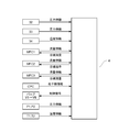
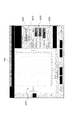
- 1 is an overall configuration diagram of a particle number measurement system according to an embodiment of the present invention. It is an information transmission figure which shows the flow of the information in the embodiment. It is a perspective view of the 1st diluter of the embodiment. It is a perspective view of the 2nd diluter of the embodiment. It is a longitudinal cross-sectional view along the central axis of the interior space of the diluter of the embodiment. It is a longitudinal cross-sectional view along the central axis of the inlet tube of the diluter of the embodiment. It is a cross-sectional view along the central axis of the introduction pipe of the diluter of the same embodiment.
- the exhaust gas of the engine is guided from the exhaust gas introduction port PT1 to the main flow path ML provided therein, and diluted, vaporized, and the like, and then is supplied to the main flow path ML.
- the PM which is a solid particle in the exhaust gas, is measured by the provided particle number measuring device 2.
- the exhaust gas introduction port PT1 is connected to an exhaust line from an engine (not shown).
- the exhaust gas introduction port PT1 is diluted with, for example, a direct exhaust gas from the engine or a full-flow dilution tunnel or a diversion dilution tunnel.
- the exhaust gas is guided.
- the exhaust gas is used to include the diluted exhaust gas as described above.
- Stage 1 diluters PND1 and PND2, and are diluted by air as a dilution gas.
- air is supplied from the dilution gas introduction port PT2 through the plurality of dilution gas channels DL1 to DL3 via the regulator REG to various parts of the main channel ML or the second bypass channel BL2.
- the first bypass flow path BL1 merges with the main flow path ML downstream of a particle number measuring device 2 described later, and maintains a constant flow rate through the open / close valve V2 and the bypass flow path BL1, etc. Constant flow device CFO1 is provided in this order. Furthermore, the main channel ML and the bypass channel BL1 are arranged downstream of the junction of the main channel ML and the bypass channel (including the first bypass channel BL1 and other bypass channels BL2 and BL3 described later).
- a suction pump P is connected to introduce the exhaust gas under a negative pressure of BL3.
- a buffer chamber BC for smoothing fluctuations in the suction force of the suction pump P is provided in the vicinity of the upstream side of the suction pump P.
- the first diluter (upstream diluter) PND1 is provided at or near the downstream of the connection point between the main flow path ML and the dilution gas flow path DL, and heats the exhaust gas introduced into the first diluter PND1. In addition, the exhaust gas is diluted.
- the exhaust gas that is the gas to be diluted introduced into the first diluter PND1 is measured by the flow rate measuring mechanism 3 provided upstream of the first diluter PND1, more specifically, upstream of the connection point. ing.
- the flow rate measuring mechanism 3 adjusts the temperature of the fluid, the orifice part 31 that becomes a fluid resistance, the pressure sensor 32 that measures the differential pressure of the orifice part 31, the pressure sensor 33 that measures the absolute pressure on the upstream side, and the fluid temperature.
- the temperature controller 34 is provided, and based on the pressure information on the upstream and downstream of the orifice portion 31 and the temperature information from the temperature controller 34, the information processing device 4 (see FIG. 2 in particular) provided separately performs the first dilution.
- the mass flow rate of the exhaust gas introduced into the container PND1 can be calculated.
- the information processing apparatus 4 includes a CPU, a memory, an input unit, a display, and the like, and is a general-purpose or dedicated so-called computer in which the CPU and peripheral devices operate in cooperation according to a predetermined program stored in the memory.
- the mass flow rate of the dilution gas introduced into the first diluter PND1 is controlled by the dilution gas flow rate control unit MFC1 provided on the dilution gas flow path DL1.
- the dilution gas flow rate control unit MFC1 is provided with the target flow rate data from the information processing device 4, the actual flow rate measured by a flow sensor (not shown) provided therein is the value of the target flow rate data (hereinafter referred to as target flow rate data).
- the flow rate is controlled locally by adjusting an internal valve (not shown) so that the flow rate is also referred to.
- This target flow rate is calculated from the dilution ratio by the information processing device 4.
- an evaporator EU for vaporizing volatile particles is provided downstream of the first diluter PND1, and branches from between the first diluter PND1 and the evaporator EU, so that the particle number measuring device 2
- a second bypass flow path BL2 that joins the main flow path ML is provided downstream.
- the evaporator EU is heated to 300 to 400 degrees.
- a dilution gas flow path DL2 provided with a dilution gas flow rate control unit MFC2 is connected to the second bypass flow path BL2.
- the bypass flow path BL2 is provided with a switching flow valve C3 and a constant flow device CFO2 such as a critical orifice that keeps the flow rate flowing through the second bypass flow path BL2 constant.
- the dilution gas flow rate control unit MFC2 is controlled by the information processing device 4 to adjust the dilution gas flowing into the second bypass flow path BL2, and as a result, the second bypass flow from the main flow path ML.
- the mass flow rate of the exhaust gas flowing into the flow path BL2 is adjusted.
- the second diluter (downstream diluter) PND2 is provided at or near the connection point between the main flow path ML and the dilution gas flow path DL3, and cools the exhaust gas introduced into the second diluter PND2. In addition, the exhaust gas is diluted.
- the dilution gas flow introduced into the second diluter PND2 is controlled in mass flow rate by the dilution gas flow rate control unit MFC3 provided in the dilution gas flow path DL3.
- the dilution gas flow rate control unit MFC3 like the dilution gas flow rate control unit MFC1, receives the target flow rate data from the information processing device 4, and is measured by a flow sensor (not shown) provided therein. However, the flow rate is controlled locally by adjusting an internal valve (not shown) so that the value of the target flow rate data (hereinafter also referred to as a target flow rate) is obtained. This target flow rate is calculated from the dilution ratio by the information processing device 4.
- the pipe from the first diluter PND1 and the vicinity thereof to the second diluter PND2 is heated to, for example, 150 ° C. or more by a temperature controller having a heating means such as a heater (not shown). This prevents PM from adhering or agglomerating on the inner wall of the pipe, thereby suppressing counting errors.
- a particle number measuring device 2 for measuring the number of solid particles in the exhaust gas diluted by the first diluter PND1 and the second diluter PND2 is provided via an open / close valve V5.
- BL3 is provided downstream of the second diluter PND2.
- the bypass channel BL3 is provided with a constant flow rate device CFO3 such as a critical orifice and an opening / closing valve V4 in this order to keep the flow rate flowing through the bypass channel BL3 constant.
- An open air passage AL having an open / close valve V6 and a filter in this order is formed between the open / close valve V5 and the particle number measuring device 3, and the open / close valve V5 is closed when the suction pump P is stopped. When opened, the open / close valve V6 is opened to open the particle number measuring device 2 to the atmosphere.
- the particle number measuring apparatus 2 mixes organic gas such as alcohol or butanol in a supersaturated state and adheres to the PM in the exhaust gas, thereby growing the PM to a large diameter, and discharging the grown PM from the slit.
- the particles that come out are counted with a laser beam. Since this particle number measuring device 2 is configured to discharge the grown PM from the slit, the slit has a function as a constant flow device, and the particle measuring device 2 has an exhaust gas at a constant flow rate. Will flow.
- the information processing apparatus 4 of this embodiment includes a dilution gas flow rate Q 1 that is controlled by the dilution gas flow rate control unit MFC3, device flow rate Q 2 and a third bypass passage is a flow through the particle number measuring apparatus 2
- the dilution ratio of the exhaust gas is calculated from the total flow rate Q 2 + Q 3 of the set flow rate Q 3 of the constant flow device CFO 3 on BL 3 .
- the information processing device 4 calculates the dilution ratio by (Q 2 + Q 3 ) / (Q 2 + Q 3 ⁇ Q 1 ).
- the information processing apparatus 4 of the present embodiment closes the opening / closing valve V5 provided upstream of the particle number measuring apparatus 2, opens the opening / closing valve V4 provided in the third bypass flow path BL3, and the dilution gas flow rate control unit MFC3 calibrating the third set flow rate of the constant flow apparatus CFO3 on bypass passage BL3 by flowing a controlled flow rate Q 1 on the third bypass passage BL3.
- the pressure and temperature in the vicinity of the upstream of the constant flow device CFO3 at the time of calibration are measured by the pressure sensor P1 and the temperature sensor T1, and the information processing apparatus 4 stores the measurement data in association with the calibration data.
- the information processing device 4 is controlled by the dilution gas flow rate control unit MFC3 by closing the open / close valve V4 provided in the third bypass flow path BL3 and opening the open / close valve V5 provided upstream of the particle number measuring device 2. to calibrate the device flow rate of the particle number measuring device 2 by passing a flow Q 1 to the main flow path ML.
- the pressure and temperature in the vicinity of the upstream of the particle number measuring device 2 at the time of calibration are measured by the pressure sensor P2 and the temperature sensor T2, and the information processing device 4 stores the measurement data in association with the calibration data.
- the information processing apparatus 4 of the present embodiment includes the temperature and pressure in the vicinity of the upstream of the constant flow device CFO3 at the time of calibration of the constant flow device CFO3 on the third bypass flow channel BL3, and the third bypass flow channel at the time of particle number measurement.
- the set flow rate of the constant flow device on the bypass flow path is corrected using the temperature and pressure near the upstream of the constant flow device CFO3 on BL3 as parameters (corrected set flow rate Q 3 ′).
- the information processing device 4 is configured to detect the temperature and pressure in the vicinity of the upstream of the particle number measuring device 2 at the time of calibration of the device flow rate of the particle number measuring device 2, and the temperature and pressure in the vicinity of the upstream of the particle number measuring device 2 at the time of particle number measurement.
- the information processing apparatus 4 calculates the dilution ratio using the apparatus flow rate Q 2 ′ and the set flow rate Q 3 ′ obtained as a result of the correction so that the dilution ratio in the second diluter PND2 becomes constant.
- Target flow rate data is given to the dilution gas flow rate controller MFC3.
- the particle number measuring system has one end connected to the main flow path having one end connected to the exhaust gas introduction port for introducing the exhaust gas of the engine, and one end connected to the dilution gas introduction port for introducing the dilution gas.
- a dilution gas flow path having an end connected to the main flow path, an evaporator provided in the main flow path for vaporizing volatile particles in the exhaust gas, a downstream side of the evaporator, and the evaporation
- a downstream diluter for diluting the exhaust gas by mixing the exhaust gas that has passed through the vessel, and a particle number measuring device for measuring the number of solid particles in the exhaust gas diluted by the downstream diluter
- a body having a rotating body-shaped internal space whose diameter decreases from one end to the other end, and along the central axis of the internal space or perpendicular to the central axis Established
- An introduction pipe for introducing exhaust gas and dilution gas into the internal space, and a derivation for exhausting the exhaust gas diluted by the swirling flow generated in the internal space to the outside of the internal space.
- the body is provided such that the central axis of the inner space thereof is substantially horizontal, the introduction pipe is connected to the evaporator, and the outlet pipe is connected to
- the downstream diluter has an introduction pipe and a lead-out pipe orthogonal to each other, and the lead-out pipe leads out the exhaust gas diluted by the swirling flow in the internal space of the body. Since the exhaust gas and dilution gas can be mixed thoroughly and the flow direction can be changed by the side diluter, the volume occupied by the pipe due to the bending radius based on the flow velocity can be eliminated as in the past, and it is compact.
- the flow path direction can be converted to In particular, in the downstream diluter, since the central axis of the internal space is provided so as to be substantially horizontal, the particles from the downstream diluter to the particle number measuring device are in a straight pipe shape, and the particles in the pipe The diluted exhaust gas can be sent to the particle number measuring device without causing accumulation or the like. Moreover, it is possible to prevent the system as a whole from being complicated due to the structure in which the downstream diluter is not installed on the lower side in the vertical direction of the particle number measuring apparatus having a large capacity and weight.
- the downstream side diluter and its downstream are considered to be at room temperature without having a structure for heating the exhaust gas and the piping, so the temperature falls and particles may adhere to the piping, but the piping can be shortened, It is possible to prevent particles from adhering to the pipe.
- the flow path in which the exhaust gas and the dilution gas are mixed can be made longer, and further, the swirl flow leads from the other end to the one end. Since the exhaust gas and the dilution gas that flow backward are led out to the outside from the outlet, the exhaust gas and the dilution gas can be sufficiently mixed without lengthening the piping.
- the inlet pipe connecting part in the evaporator and the outlet pipe in the particle number measuring device are used. It is desirable that the connecting portion is arranged orthogonally.
- an upstream side diluter is provided on the upstream side of the evaporator, and dilutes the exhaust gas by mixing it with the exhaust gas introduced inside.
- the upstream diluter has a rotating body-shaped internal space whose diameter decreases from one end to the other end, and is orthogonal to or along the central axis of the internal space.
- a lead-out pipe that leads out, and the upstream diluter is heated and the downstream diluter is cooled, and a heater is attached to the outer wall of the body in the upstream diluter. It is desirable that mounting plane which is are formed.
- the exhaust gas may contain foreign substances other than the measurement target substance or solid particles larger than a predetermined particle diameter, and in order to suitably remove the foreign substances and large particles
- the inner space has a rotating body shape whose diameter gradually decreases as it goes vertically downward, and it is desirable that a dust collecting portion is provided below the inner space.
- the upstream diluter is preferably provided with a function of removing foreign matters and solid particles larger than the size of the measurement target substance.
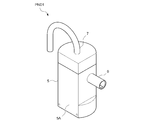
- the first diluter PND1 and the second diluter PND2 of the present embodiment include a body 5 having an internal space S into which exhaust gas and dilution gas are introduced, as shown in FIGS. 5 is provided with an introduction pipe 6 for introducing exhaust gas and dilution gas into the internal space S, and a lead-out pipe 7 for leading out exhaust gas diluted from the internal space S.
- 3 shows the first diluter PND1
- FIG. 4 shows the second diluter PND2
- the configurations of the first diluter PND1 and the second diluter PND2 are the same except for the outlet pipe 7.
- the body 5 has a rotating body-shaped internal space S having a tapered portion that gradually decreases in diameter from one end to the other end.
- the internal space S includes a cylindrical space portion S1 and a conical space portion S2.
- the other end portion of the internal space S is provided with a dust collection portion 8 for collecting dust contained in the exhaust gas introduced into the internal space S so as to communicate with the internal space S. .
- an attachment plane 5A for attaching a heater for heating the exhaust gas introduced into the internal space S when used in the first diluter PND1 is formed on the outer wall of the body 5.
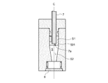
- the introduction pipe 6 dilutes the exhaust gas and the dilution gas into the internal space S so that the exhaust gas and the dilution gas flow downward (on the other end side) along the inner peripheral wall of the body 5. It introduces from the cylindrical part. Specifically, as shown in FIG. 6, the introduction pipe 6 is orthogonal to the central axis C of the internal space S in the cylindrical space S ⁇ b> 1 above the tapered portion (conical space S ⁇ b> 2) in the internal space S. Further, as shown in FIG. 7, the inflow direction of the exhaust gas and the dilution gas is provided at a position that is tangential to the cylindrical wall 501 that is the inner peripheral wall of the body 5.
- the exhaust gas and the dilution gas that flowed in from the introduction pipe 6 change from a linear flow to a vortex flow in the cylindrical space portion S1, descend while rotating along the cylindrical wall 501 (toward the other end), and enter the conical space portion S2. When it reaches, it further descends (toward the other end) while increasing the rotation speed, reverses the direction near the lower end of the conical space S2, rises while rotating the center, and is discharged through the outlet pipe 7. .
- the lead-out pipe 7 is provided along the central axis C of the internal space S at least in the internal space S, and the lead-out port 7 a is in the internal space S (specifically, a cylindrical space).
- the exhaust gas diluted by the swirling flow generated in the internal space S is led out of the internal space S. That is, the outlet pipe 7 and the inlet pipe 6 in the internal space S are provided to be orthogonal to each other. Thereby, it is set as the structure which changes the flow path direction of the piping which comprises the main flow path ML in the diluters PND1 and PND2.
- the outlet 7 a of the outlet pipe 7 is positioned below the opening of the inlet pipe 6 so that the exhaust gas and dilution gas do not flow directly from the inlet pipe 6 to the outlet pipe 7.
- the outlet pipe 7 of the first diluter PND1 is a curved pipe that curves outside the internal space S as shown in FIG. 3, and the outlet pipe 7 of the second diluter PND2 is the same as that shown in FIG. As shown in FIG. 3, the straight pipe is straight outside the internal space S.
- the first diluter PND1 is provided so as to be gradually reduced in diameter as the internal space S goes vertically downward. That is, the first diluter PND1 is arranged so that the central axis C of the internal space S is substantially vertical. Thereby, the dust contained in the exhaust gas introduced into the first diluter PND1 is centrifuged and accommodated in the dust collecting unit 8.
- the first diluter PND1 has a function of removing particles larger than the particle size of the solid particles contained in the exhaust gas (for example, larger than 2.5 ⁇ m).
- the second diluter PND2 is arranged so that the central axis C of the internal space S is substantially horizontal. That is, the second diluter PND2 of this embodiment does not have a dust collection function.
- the first diluter PND1 is provided above the evaporator EU so that the central axis C of the internal space S is substantially vertical.
- the outlet pipe 7 of the first diluter PND1 is curved in a U shape. Yes.
- the lead-out pipe 7 is connected to one end of an evaporator EU provided below.
- the introduction pipe 6 of the second diluter PND2 is connected to the introduction pipe connection part (exhaust gas outlet) EU1 of the evaporator EU.
- the second diluter PND2 is provided such that the central axis C of the internal space S is substantially horizontal.
- the outlet pipe 7 of the second diluter PND2 has a straight pipe shape, and the particle number measuring device 2 Connected to the outlet pipe connecting portion (exhaust gas inlet) 21.
- the inlet pipe connecting part EU1 of the evaporator EU and the outlet pipe connecting part 21 of the particle number measuring device 2 are provided on the base body 9 so as to be orthogonal to each other in a substantially horizontal plane.
- PND2 is provided in the horizontal direction side so that the inlet pipe connection part EU1 of the evaporator EU and the outlet pipe connection part 21 of the particle number measuring device 2 may be opposed. More specifically, the cylindrical space portion side of the second diluter PND2 is provided so as to face the outlet tube connecting portion of the particle number measuring device 2.
- the first diluter has a dust collecting function and no dust remover is provided upstream of the first diluter, but the first diluter has no dust collecting function, A dust remover may be provided upstream of one diluter. At this time, it is not necessary to provide the first diluter so that the internal space S is arranged along the vertical direction.
- the 1st diluter and the 2nd diluter are set as the same structure, it is good also as a different structure. In this case, it is good also as a structure which provides a dust collecting part in a 1st diluter, and does not provide a dust collecting part in a 2nd diluter.
- the diluter has one introduction pipe for introducing both the exhaust gas and the dilution gas into the internal space.
- the diluter has an introduction pipe for the exhaust gas and the dilution gas for introducing the exhaust gas into the internal space. It may have an introduction pipe for dilution gas introduced into the space.
- the outlet pipe of the first diluter was a curved pipe
- the outlet pipe of the second diluter was a straight pipe, but these outlet pipes depend on the arrangement of components connected downstream of the diluter. It can be changed as appropriate.
- the diluter of the above embodiment is configured such that the introduction pipe is provided perpendicular to the central axis of the internal space and the outlet pipe is provided along the central axis of the internal space. It may be provided along the central axis of the internal space, and the outlet pipe may be provided orthogonal to the central axis of the internal space. In this case, in order to generate a swirling flow in the internal space, it is desirable to provide a stirring blade in the internal space.
- the particle number measurement system includes an exhaust gas introduction port for introducing engine exhaust gas, a dilution gas introduction port for introducing dilution gas, and a dilution gas in the exhaust gas introduced therein.
- An information processing device that displays on a display switchable particle number information after dilution and particle number information before dilution obtained from the diluted particle number information and the dilution ratio of the dilution unit. It is characterized by that.
- the particle number measurement system further includes an evaporator that vaporizes volatile particles in the exhaust gas
- thermophoresis There exists a problem that the particle
- the information processing apparatus in addition to the particle number information after dilution and the particle number information before dilution, Particle number information after loss correction obtained from the particle number information after dilution, the dilution ratio of the dilution unit, and the particle loss coefficient determined from at least the particle number loss after passing through the evaporator at the dilution ratio It is desirable to be displayed on the display in a switchable manner.
- the particle loss coefficient is, for example, a PCRF (Particle Concentration Reduction Factor) defined in the ECE standard (ECE Regulation).
- the particle number information after dilution not only the particle number information after dilution, the particle number information before dilution and the particle number information after loss correction can be displayed, but the user can be prevented from mistaking each particle number information, and the display space There is no need to reduce the particle size, and the usability of the particle number measuring system can be improved.
- the information processing apparatus can switch between the particle number information after dilution and the particle number information before dilution, the particle number information after dilution, the particle number information before dilution, and the A display for selection for the user to select a second display screen capable of switching the particle number information after loss compensation is displayed on the display, and the display screen selected by the selection display is further displayed. It is desirable to display the above. In this case, the user can intentionally select the first display screen and the second display screen, and it is possible to easily prevent the particle number information displayed on the screen from being mistaken.
- the information processing apparatus includes a selection check box as the selection display, and displays a dilution ratio setting screen for setting a dilution ratio of the dilution unit, and the user displays the second particle number information display.
- a screen it is desirable that only a dilution ratio with a predetermined particle loss coefficient be displayed on the dilution ratio setting screen so as to be selectable.
- the information processing apparatus displays a dilution ratio setting screen for setting the dilution ratio of the dilution unit, and the dilution ratio input to the dilution ratio setting screen is displayed.
- the first display screen capable of switching the particle number information after dilution and the particle number information before dilution, the particle number information after dilution, the particle number information before dilution, and the loss compensated It is desirable to display on the display one of the display screens that can switch the particle number information.
- the information processing device 4 of the particle number measurement system 100 of the present embodiment includes the diluted particle number information obtained from the measurement result of the particle number measurement device 2, the diluted particle number information, and the dilution unit dilution.
- the particle number information before dilution obtained from the ratio and the particle number information after loss obtained from the particle number information after dilution and the particle loss coefficient are displayed on the display in a switchable manner.
- an example of the particle number concentration [number / cm 3 ] is shown as the particle number information.
- the particle number information before dilution is information obtained by multiplying the particle number information after dilution and the dilution ratio of the dilution unit (specifically, the overall dilution ratio of the first diluter PND1 and the second diluter PND2).
- the particle number information after loss correction is information obtained by multiplying the particle number information after dilution and the particle loss coefficient.
- the particle loss coefficient is a coefficient determined from the dilution ratio of the dilution unit and the particle number loss after the particles have passed through at least the evaporator EU at the dilution ratio.
- the particle loss coefficient is a coefficient obtained by combining the dilution ratio of the dilution unit and at least the particle number loss after the particles have passed through the evaporator EU at the dilution ratio, and is determined for each dilution ratio.
- the particle loss coefficient it is obtained from at least the particle loss in the vicinity of the evaporator EU.
- the particle loss due to pipe bending or the like is also considered. It is determined in consideration of particle loss in a pipe (including various devices such as an evaporator EU provided in the pipe) connecting the particle number measuring device CPC from the gas introduction port PT1.
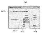
- the information processing apparatus 4 displays a dilution rate setting screen W1 shown in FIG. 9 on the display in setting the dilution rate before starting the concentration of the exhaust gas particles.
- This dilution rate setting screen W1 is a screen for setting the dilution rate of the first dilution unit (first dilution device PND1) and the dilution rate of the second dilution unit (second dilution device PND2).
- the dilution ratio of the second diluter PND2 is a fixed value (15 times in FIG. 9)
- the dilution rate setting screen W1 is a screen for setting the dilution ratio of the first diluter PND1. is there.
- the dilution ratio of the first diluter PND1 can be arbitrarily set between 10 times and 200 times by the user inputting text in the dilution ratio input box W11.
- symbol W13 is a determination button for determining the dilution rate
- symbol W14 is an end button for ending the dilution ratio setting.
- the dilution rate setting screen W1 includes a selection display for the user to select the first display screen W2 (see FIG. 11) and the second display screen W3 (see FIG. 12), specifically, a selection check box W12. It is displayed.
- the information processing apparatus 4 displays the second display screen W3 on the display.
- the selection check box W12 is not checked, the information processing apparatus 4 displays the first display screen W2 on the display.
- the first display screen W2 is a display screen capable of switching the particle number concentration after dilution and the particle number concentration before dilution, and the particle number concentration after dilution (in FIG. Raw Count ”) and the particle number concentration before dilution (“ Count ⁇ Total DF ”in FIG. 11) and the particle number concentration selected by the display switching unit W21 in real time, for example.
- the display switching unit W21 enables the particle number concentration after dilution (Raw Count) and the particle number concentration before dilution (Count ⁇ Total DF) to be selected by a pull-down menu when the user selects with a pointing device.
- the first display screen W2 has a dilution ratio display area W23 for displaying the dilution ratio of the dilution unit during the particle number measurement, and a time-series data display area W24 for indicating a change with time in the particle number concentration.
- the dilution ratio display area W23 displays the dilution ratio of the first diluter PND1, the dilution ratio of the second diluter PND2, and the overall dilution ratio of the two diluters PND1 and PND2.
- the first display screen W2 also has a status display area W25 for displaying the sample line selected by the line selection mechanism SCU.
- the second display screen W3 is a display screen capable of switching the particle number concentration after dilution, the particle number concentration before dilution, and the particle number concentration after loss correction. Switching between the number concentration (“CPC Count” in FIG. 12), the particle number concentration before dilution (“Count ⁇ Total DF” in FIG. 12) and the particle number concentration after loss correction (“Count ⁇ PCRF” in FIG. 12) And a particle number information display region W32 for displaying the particle number concentration selected by the display switching unit W31 in real time, for example. Other configurations are the same as those of the first display screen W2, the reference W33 is a dilution ratio display area, and the reference W34 is a time-series data display area. The second display screen W3 also has a status display area W35 for displaying the sample line selected by the line selection mechanism SCU. In FIG. 12, the particle number information display area W32 is hidden by the pull-down menu of the display switching unit W31.
- the dilution ratio input box W11 can select only a dilution ratio with a predetermined particle loss coefficient.
- the information processing apparatus 4 includes only those dilution ratios in which the particle loss coefficient can be selected in the dilution ratio input box W11.
- a pull-down menu is displayed. The dilution ratio of the first diluter PND1 is set by selecting the dilution ratio included in this pull-down menu.
- the dilution ratio of the second diluter is a fixed value.
- the user may arbitrarily set the dilution ratio.
- requiring a particle loss coefficient is not restricted to 30 nm, 50 nm, and 100 nm, Other particle diameters may be sufficient.
- the average value (arithmetic mean) of the loss coefficient obtained for each particle diameter is used above, but the loss obtained for each particle diameter depends on the properties of the exhaust gas to be measured. A weighted average of coefficients may be used.
- the dilution ratio of the first diluter can be selected from the pull-down menu.
- other text may be input.
- the dilution ratio setting screen may not have a selection check box.
- the processing device may automatically display the second display screen on the display. If this is the case, the user's operation can be simplified.
- the present invention is not limited to the above embodiment.
- the case where the constant flow device (CFO) provided inside the particle number measuring device 2 is not temperature-controlled is assumed, and the device flow rate of the particle number measuring device 2 is set to the number of particles. Calibration is performed using the pressure and temperature in the vicinity of the upstream side of the measuring device 2.
- the constant flow rate device (CFO) provided inside the particle number counting device 2 is temperature-controlled, the device flow rate of the particle number measuring device 2 uses the pressure near the upstream of the particle number measuring device 2. It is not necessary to calibrate using the temperature near the upstream.
- the pressure sensor P1 and the temperature sensor T1 are provided in the vicinity of the upstream of the constant flow rate device CFO3 on the third bypass flow path BL3, and the pressure sensor P1 and the temperature sensor T1 in the vicinity of the upstream of the particle number measuring device in the main flow path ML.
- the temperature sensor T1 is provided, the pressure sensor and the temperature sensor may be shared. Specifically, a common pressure sensor and temperature sensor may be provided in the vicinity of the branch point upstream of the main channel ML and the third bypass channel BL3.
- the configuration of the particle number measurement system can be simplified and made compact, and the cost can be reduced.
Landscapes
- Health & Medical Sciences (AREA)
- Life Sciences & Earth Sciences (AREA)
- Engineering & Computer Science (AREA)
- Biomedical Technology (AREA)
- Molecular Biology (AREA)
- Physics & Mathematics (AREA)
- Chemical & Material Sciences (AREA)
- Analytical Chemistry (AREA)
- Biochemistry (AREA)
- General Health & Medical Sciences (AREA)
- General Physics & Mathematics (AREA)
- Immunology (AREA)
- Pathology (AREA)
- Sampling And Sample Adjustment (AREA)
Abstract
Description
PT1 ・・・排出ガス導入ポート
PT2 ・・・希釈ガス導入ポート
ML ・・・メイン流路
DL ・・・希釈ガス流路
PND ・・・希釈器
MFC ・・・希釈ガス流量制御部
V5 ・・・バルブ
2 ・・・粒子数計測装置
CFO3・・・定流量器
V4 ・・・バルブ
BL ・・・バイパス流路
P ・・・吸引ポンプ
4 ・・・情報処理装置
このように構成した本実施形態に係る粒子数計測システム100によれば、希釈ガス流量制御部MFC3により制御される希釈ガス流量Q1と、粒子数計測装置2の装置流量Q2及びバイパス流路BL3上の定流量器CFO3の設定流量Q3の合計流量Q2+Q3と、から排出ガスの希釈率を算出するようにしているので、従来第2希釈器PND2に流入する排出ガスの流量を測定していた流量測定機構を不要とすることができ、システム構成を簡単化及びコンパクト化することができるとともに、コストダウンを可能にすることができる。また、従来、粒子数計測装置2が設けられた流路ML及びバイパス流路BL毎に設けていた吸引ポンプを共通化させているので、これによってもシステム構成を簡単化及びコンパクト化することができ、システムのコストダウンを可能にすることができる。
Claims (5)
- エンジンの排出ガスを導入するための排出ガス導入ポートと、
希釈ガスを導入するための希釈ガス導入ポートと、
前記排出ガス導入ポートに一端が接続されたメイン流路と、
前記希釈ガス導入ポートに一端が接続され、他端が前記メイン流路に接続された希釈ガス流路と、
前記メイン流路及び前記希釈ガス流路の接続点又はその下流近傍に設けた希釈器と、
前記希釈ガス流路に設けられ、前記希釈器に導入される希釈ガスの流量を制御する希釈ガス流量制御部と、
前記希釈器の下流にバルブを介して設けられ、希釈された排出ガス中の固体粒子数を計測するものであって、定流量機能を有する粒子数計測装置と、
前記メイン流路における前記希釈器及び前記粒子数計測装置の間から分岐して設けられ、定流量器及びバルブが設けられたバイパス流路と、
前記メイン流路及び前記バイパス流路の合流点下流に接続され、前記メイン流路及び前記バイパス流路に排出ガスを導入するための吸引ポンプと、
前記希釈ガス流量制御部により制御される希釈ガス流量と、前記粒子数計測装置を流れる流量である装置流量及び前記バイパス流路上の定流量器の設定流量の合計流量と、から排出ガスの希釈率を算出する情報処理装置と、を備える粒子数計測システム。 - 前記情報処理装置が、前記粒子数計測装置の上流に設けたバルブを閉じ、前記バイパス流路に設けたバルブを開けて、前記希釈ガス流量制御部により制御された流量を前記バイパス流路上に流すことによって前記バイパス流路上の定流量器の設定流量を校正する請求項1記載の粒子数計測システム。
- 前記情報処理装置が、前記バイパス流路に設けたバルブを閉じ、前記粒子数計測装置の上流に設けたバルブを開けて、前記希釈ガス流量制御部により制御された流量を前記メイン流路に流すことによって前記粒子数計測装置の装置流量を校正する請求項1記載の粒子数計測システム。
- 前記情報処理装置が、前記バイパス流路上の定流量器の校正時におけるその定流量器上流近傍の温度及び圧力と、粒子数測定時における前記バイパス流路上の定流量器上流近傍の温度及び圧力とをパラメータとして、前記バイパス流路上の定流量器の設定流量を補正する請求項2記載の粒子数計測システム。
- 前記情報処理装置が、前記粒子数計測装置の装置流量の校正時におけるその粒子数計測装置上流近傍の圧力と、粒子数測定時における前記粒子数計測装置上流近傍の圧力とをパラメータとして、前記粒子数計測装置の装置流量を補正する請求項2記載の粒子数計測システム。
Priority Applications (3)
| Application Number | Priority Date | Filing Date | Title |
|---|---|---|---|
| EP10761658.3A EP2418471B1 (en) | 2009-04-07 | 2010-04-02 | System for determining number of particles |
| US13/259,018 US8794048B2 (en) | 2009-04-07 | 2010-04-02 | System for determining number of particles |
| CN2010800130895A CN102362167B (zh) | 2009-04-07 | 2010-04-02 | 粒子数测量系统 |
Applications Claiming Priority (6)
| Application Number | Priority Date | Filing Date | Title |
|---|---|---|---|
| JP2009-092915 | 2009-04-07 | ||
| JP2009092915 | 2009-04-07 | ||
| JP2009101443A JP5489324B2 (ja) | 2009-04-17 | 2009-04-17 | 粒子数計測システム |
| JP2009-101359 | 2009-04-17 | ||
| JP2009101359A JP5588120B2 (ja) | 2009-04-17 | 2009-04-17 | 粒子数計測システム |
| JP2009-101443 | 2009-04-17 |
Publications (1)
| Publication Number | Publication Date |
|---|---|
| WO2010116959A1 true WO2010116959A1 (ja) | 2010-10-14 |
Family
ID=42936243
Family Applications (1)
| Application Number | Title | Priority Date | Filing Date |
|---|---|---|---|
| PCT/JP2010/056090 Ceased WO2010116959A1 (ja) | 2009-04-07 | 2010-04-02 | 粒子数計測システム |
Country Status (4)
| Country | Link |
|---|---|
| US (1) | US8794048B2 (ja) |
| EP (1) | EP2418471B1 (ja) |
| CN (1) | CN102362167B (ja) |
| WO (1) | WO2010116959A1 (ja) |
Cited By (2)
| Publication number | Priority date | Publication date | Assignee | Title |
|---|---|---|---|---|
| CN106092839A (zh) * | 2015-04-30 | 2016-11-09 | 株式会社堀场制作所 | 排气测量装置以及排气测量方法 |
| JP2017133925A (ja) * | 2016-01-27 | 2017-08-03 | 富士電機株式会社 | 粒子分析装置 |
Families Citing this family (8)
| Publication number | Priority date | Publication date | Assignee | Title |
|---|---|---|---|---|
| AT513791B1 (de) * | 2014-04-25 | 2016-05-15 | Avl List Gmbh | Partikelmessgerät und ein Verfahren zum Betreiben des Partikelmessgerätes |
| JP2014134555A (ja) * | 2014-04-28 | 2014-07-24 | Horiba Ltd | 粒子数計測システム |
| CN104181085A (zh) * | 2014-08-28 | 2014-12-03 | 无锡硅奥科技有限公司 | 一种激光尘埃粒子计数器 |
| DE102017110793A1 (de) | 2016-05-25 | 2017-11-30 | FEV Europe GmbH | Abgasanalyseanlage zur Analyse eines Abgases einer Verbrennungskraftmaschine und Verfahren zum Betreiben einer solchen Abgasanalyseanlage |
| JP6714441B2 (ja) * | 2016-06-09 | 2020-06-24 | アズビル株式会社 | 粒子検出装置及び粒子検出装置の制御方法 |
| WO2021014740A1 (ja) * | 2019-07-22 | 2021-01-28 | 株式会社堀場製作所 | 排ガス分析装置、ガス供給方法、及び排ガスサンプリング装置 |
| EP4042139A4 (en) * | 2019-09-30 | 2023-11-22 | TSI Incorporated | Mirror calibration of multiple flow-measurement devices |
| EP4130706A4 (en) | 2020-03-26 | 2024-03-27 | HORIBA, Ltd. | DILUTER, ANALYSIS SYSTEM, AND ANALYSIS METHOD |
Citations (10)
| Publication number | Priority date | Publication date | Assignee | Title |
|---|---|---|---|---|
| JPH01143932A (ja) * | 1987-11-05 | 1989-06-06 | Horiba Instr Inc | 内燃機関の排気ガスの質量流量計測装置を較正する方法、そのための装置および比例サンプル抽出方法 |
| JP2000028499A (ja) * | 1998-07-15 | 2000-01-28 | Farm Tec:Kk | 排気ガス中の混合物質捕集装置 |
| JP2001188031A (ja) * | 1999-10-18 | 2001-07-10 | Firmware Technology Co Ltd | 排気ガス中の粒子状物質の測定方法および測定装置 |
| JP2006194726A (ja) | 2005-01-13 | 2006-07-27 | Mazda Motor Corp | Pm粒子数計測装置 |
| JP2006275801A (ja) * | 2005-03-29 | 2006-10-12 | Horiba Ltd | 排気ガス成分分析装置 |
| JP2008164446A (ja) | 2006-12-28 | 2008-07-17 | Horiba Ltd | 粒子数計測システム |
| JP2008164413A (ja) * | 2006-12-28 | 2008-07-17 | Horiba Ltd | 排出ガスサンプリング分析システム |
| JP2008164419A (ja) * | 2006-12-28 | 2008-07-17 | Horiba Ltd | 粒子数計測システム及びその制御方法 |
| JP2008530558A (ja) * | 2005-02-11 | 2008-08-07 | 株式会社堀場製作所 | 広範囲連続希釈装置 |
| JP2009510448A (ja) * | 2005-09-29 | 2009-03-12 | 株式会社堀場製作所 | エンジン排気希釈用サンプラ |
Family Cites Families (20)
| Publication number | Priority date | Publication date | Assignee | Title |
|---|---|---|---|---|
| JPS5177291A (ja) | 1974-12-02 | 1976-07-05 | Hitachi Ltd | Haigasusanpuringusochi |
| JPS588735B2 (ja) | 1978-11-10 | 1983-02-17 | 株式会社堀場製作所 | 定容量希釈サンプリング装置 |
| JPS55167554U (ja) | 1979-05-18 | 1980-12-02 | ||
| JPS58153550A (ja) | 1982-03-08 | 1983-09-12 | Keiichi Isotani | 粉粒体捕集機 |
| JPS5982561U (ja) | 1982-11-29 | 1984-06-04 | 三菱重工業株式会社 | ダスト捕集装置 |
| JPS59130558A (ja) | 1983-01-13 | 1984-07-27 | Fuji Electric Corp Res & Dev Ltd | 排気ガス浄化用サイクロン集じん器 |
| JPS59175157U (ja) | 1983-05-09 | 1984-11-22 | 三菱重工業株式会社 | ダスト捕集装置 |
| JPH06341950A (ja) | 1993-05-29 | 1994-12-13 | Horiba Ltd | 光学的ガス濃度計測方法およびその装置 |
| EP1151270A2 (en) | 1999-02-02 | 2001-11-07 | RUPPRECHT & PATASHNICK CO., INC. | Differential particulate mass monitor with intrinsic correction for volatilization losses |
| JP2001215230A (ja) | 2000-02-03 | 2001-08-10 | Shimadzu Corp | 分析装置 |
| JP3731656B2 (ja) | 2002-04-16 | 2006-01-05 | 横河電機株式会社 | パーティクル捕集方法及びパーティクル捕集装置 |
| JP4810922B2 (ja) | 2004-08-10 | 2011-11-09 | 日産自動車株式会社 | Pm堆積量推定制御装置 |
| CN100491704C (zh) * | 2004-08-10 | 2009-05-27 | 日产自动车株式会社 | 柴油机微粒滤清器中微粒沉积量的推算装置及方法 |
| JP2006194744A (ja) | 2005-01-13 | 2006-07-27 | Sysmex Corp | 測定装置用データ処理装置、及びアプリケーションプログラム |
| EP1914545B1 (en) * | 2005-03-29 | 2016-05-04 | Horiba, Ltd. | Vehicle-mountable exhaust gas analyzer |
| JP2008096182A (ja) | 2006-10-10 | 2008-04-24 | Shimadzu Corp | 分析装置 |
| US7647811B2 (en) | 2006-12-21 | 2010-01-19 | Horiba Ltd. | Solid particle counting system with valve to allow reduction of pressure pulse at particle counter when vacuum pump is started |
| US7647810B2 (en) | 2006-12-21 | 2010-01-19 | Horiba Ltd. | Solid particle counting system with flow meter upstream of evaporation unit |
| WO2008111403A1 (ja) * | 2007-03-15 | 2008-09-18 | Ngk Insulators, Ltd. | 粒子状物質検出装置 |
| JP5350611B2 (ja) | 2007-06-28 | 2013-11-27 | シスメックス株式会社 | 表示方法および試料分析装置 |
-
2010
- 2010-04-02 WO PCT/JP2010/056090 patent/WO2010116959A1/ja not_active Ceased
- 2010-04-02 CN CN2010800130895A patent/CN102362167B/zh active Active
- 2010-04-02 US US13/259,018 patent/US8794048B2/en active Active
- 2010-04-02 EP EP10761658.3A patent/EP2418471B1/en active Active
Patent Citations (10)
| Publication number | Priority date | Publication date | Assignee | Title |
|---|---|---|---|---|
| JPH01143932A (ja) * | 1987-11-05 | 1989-06-06 | Horiba Instr Inc | 内燃機関の排気ガスの質量流量計測装置を較正する方法、そのための装置および比例サンプル抽出方法 |
| JP2000028499A (ja) * | 1998-07-15 | 2000-01-28 | Farm Tec:Kk | 排気ガス中の混合物質捕集装置 |
| JP2001188031A (ja) * | 1999-10-18 | 2001-07-10 | Firmware Technology Co Ltd | 排気ガス中の粒子状物質の測定方法および測定装置 |
| JP2006194726A (ja) | 2005-01-13 | 2006-07-27 | Mazda Motor Corp | Pm粒子数計測装置 |
| JP2008530558A (ja) * | 2005-02-11 | 2008-08-07 | 株式会社堀場製作所 | 広範囲連続希釈装置 |
| JP2006275801A (ja) * | 2005-03-29 | 2006-10-12 | Horiba Ltd | 排気ガス成分分析装置 |
| JP2009510448A (ja) * | 2005-09-29 | 2009-03-12 | 株式会社堀場製作所 | エンジン排気希釈用サンプラ |
| JP2008164446A (ja) | 2006-12-28 | 2008-07-17 | Horiba Ltd | 粒子数計測システム |
| JP2008164413A (ja) * | 2006-12-28 | 2008-07-17 | Horiba Ltd | 排出ガスサンプリング分析システム |
| JP2008164419A (ja) * | 2006-12-28 | 2008-07-17 | Horiba Ltd | 粒子数計測システム及びその制御方法 |
Cited By (3)
| Publication number | Priority date | Publication date | Assignee | Title |
|---|---|---|---|---|
| CN106092839A (zh) * | 2015-04-30 | 2016-11-09 | 株式会社堀场制作所 | 排气测量装置以及排气测量方法 |
| US10520401B2 (en) | 2015-04-30 | 2019-12-31 | Horiba, Ltd. | Exhaust gas measurement system and exhaust gas measurement method |
| JP2017133925A (ja) * | 2016-01-27 | 2017-08-03 | 富士電機株式会社 | 粒子分析装置 |
Also Published As
| Publication number | Publication date |
|---|---|
| CN102362167A (zh) | 2012-02-22 |
| EP2418471B1 (en) | 2019-12-25 |
| EP2418471A4 (en) | 2017-11-22 |
| CN102362167B (zh) | 2013-12-25 |
| US20120090377A1 (en) | 2012-04-19 |
| US8794048B2 (en) | 2014-08-05 |
| EP2418471A1 (en) | 2012-02-15 |
Similar Documents
| Publication | Publication Date | Title |
|---|---|---|
| WO2010116959A1 (ja) | 粒子数計測システム | |
| JP6181288B2 (ja) | アイソトープ比分析器のためのガス注入システム及びアイソトープ比を決定する方法 | |
| JP5476193B2 (ja) | 粒子数計測システム | |
| JP4705116B2 (ja) | 広範囲連続希釈装置 | |
| US11222765B2 (en) | Electron microscope sample holder fluid handling with independent pressure and flow control | |
| JP2014511123A (ja) | フロー式粒子分析器の温度補償を含む流体システム | |
| CN110243658A (zh) | 一种合流式气溶胶稀释器的校准方法 | |
| US9140631B2 (en) | Method of measuring characteristics of critical orifice type constant flow rate instrument for use in multistage dilution mechanism | |
| JP5588120B2 (ja) | 粒子数計測システム | |
| CN110208165A (zh) | 一种分流式气溶胶稀释器的校准方法 | |
| JP5489324B2 (ja) | 粒子数計測システム | |
| EP2208042B1 (en) | Calibration unit for volatile particle remover | |
| CN111203118A (zh) | 一种分段调节稀释装置及系统 | |
| US7565846B2 (en) | Particulate sampler and dilution gas flow device arrangement for an exhaust sampling system | |
| JP2014134555A (ja) | 粒子数計測システム | |
| US8847156B2 (en) | Gas inlet for a process mass spectrometer | |
| JP2025509808A (ja) | 粒子モニタリングシステム、可搬型微生物エアーサンプラ、試料流体中の粒子モニタリング方法、および粒子モニタリングシステムの校正/調整方法 | |
| CN220231583U (zh) | 一种气溶胶化学成分监测仪的电离效率标定装置 | |
| JP2008164446A (ja) | 粒子数計測システム | |
| JP5118664B2 (ja) | 粒子数計測システム及びその制御方法 | |
| CN117110014A (zh) | 一种气体稀释进样装置 |
Legal Events
| Date | Code | Title | Description |
|---|---|---|---|
| WWE | Wipo information: entry into national phase |
Ref document number: 201080013089.5 Country of ref document: CN |
|
| 121 | Ep: the epo has been informed by wipo that ep was designated in this application |
Ref document number: 10761658 Country of ref document: EP Kind code of ref document: A1 |
|
| WWE | Wipo information: entry into national phase |
Ref document number: 13259018 Country of ref document: US |
|
| WWE | Wipo information: entry into national phase |
Ref document number: 2010761658 Country of ref document: EP |
|
| NENP | Non-entry into the national phase |
Ref country code: DE |
|
| WWE | Wipo information: entry into national phase |
Ref document number: 7269/CHENP/2011 Country of ref document: IN |