WO2010119925A1 - アルミニウム合金部材の溶接継手 - Google Patents
アルミニウム合金部材の溶接継手 Download PDFInfo
- Publication number
- WO2010119925A1 WO2010119925A1 PCT/JP2010/056766 JP2010056766W WO2010119925A1 WO 2010119925 A1 WO2010119925 A1 WO 2010119925A1 JP 2010056766 W JP2010056766 W JP 2010056766W WO 2010119925 A1 WO2010119925 A1 WO 2010119925A1
- Authority
- WO
- WIPO (PCT)
- Prior art keywords
- aluminum alloy
- slope
- thickness
- welded
- groove
- Prior art date
- Legal status (The legal status is an assumption and is not a legal conclusion. Google has not performed a legal analysis and makes no representation as to the accuracy of the status listed.)
- Ceased
Links
Images


Classifications
-
- B—PERFORMING OPERATIONS; TRANSPORTING
- B62—LAND VEHICLES FOR TRAVELLING OTHERWISE THAN ON RAILS
- B62D—MOTOR VEHICLES; TRAILERS
- B62D21/00—Understructures, i.e. chassis frame on which a vehicle body may be mounted
- B62D21/11—Understructures, i.e. chassis frame on which a vehicle body may be mounted with resilient means for suspension, e.g. of wheels or engine; sub-frames for mounting engine or suspensions
-
- B—PERFORMING OPERATIONS; TRANSPORTING
- B23—MACHINE TOOLS; METAL-WORKING NOT OTHERWISE PROVIDED FOR
- B23K—SOLDERING OR UNSOLDERING; WELDING; CLADDING OR PLATING BY SOLDERING OR WELDING; CUTTING BY APPLYING HEAT LOCALLY, e.g. FLAME CUTTING; WORKING BY LASER BEAM
- B23K31/00—Processes relevant to this subclass, specially adapted for particular articles or purposes, but not covered by any single one of main groups B23K1/00 - B23K28/00
- B23K31/02—Processes relevant to this subclass, specially adapted for particular articles or purposes, but not covered by any single one of main groups B23K1/00 - B23K28/00 relating to soldering or welding
-
- B—PERFORMING OPERATIONS; TRANSPORTING
- B23—MACHINE TOOLS; METAL-WORKING NOT OTHERWISE PROVIDED FOR
- B23K—SOLDERING OR UNSOLDERING; WELDING; CLADDING OR PLATING BY SOLDERING OR WELDING; CUTTING BY APPLYING HEAT LOCALLY, e.g. FLAME CUTTING; WORKING BY LASER BEAM
- B23K33/00—Specially-profiled edge portions of workpieces for making soldering or welding connections; Filling the seams formed thereby
- B23K33/004—Filling of continuous seams
- B23K33/006—Filling of continuous seams for cylindrical workpieces
-
- B—PERFORMING OPERATIONS; TRANSPORTING
- B23—MACHINE TOOLS; METAL-WORKING NOT OTHERWISE PROVIDED FOR
- B23K—SOLDERING OR UNSOLDERING; WELDING; CLADDING OR PLATING BY SOLDERING OR WELDING; CUTTING BY APPLYING HEAT LOCALLY, e.g. FLAME CUTTING; WORKING BY LASER BEAM
- B23K33/00—Specially-profiled edge portions of workpieces for making soldering or welding connections; Filling the seams formed thereby
- B23K33/004—Filling of continuous seams
- B23K33/008—Filling of continuous seams for automotive applications
-
- B—PERFORMING OPERATIONS; TRANSPORTING
- B23—MACHINE TOOLS; METAL-WORKING NOT OTHERWISE PROVIDED FOR
- B23K—SOLDERING OR UNSOLDERING; WELDING; CLADDING OR PLATING BY SOLDERING OR WELDING; CUTTING BY APPLYING HEAT LOCALLY, e.g. FLAME CUTTING; WORKING BY LASER BEAM
- B23K9/00—Arc welding or cutting
- B23K9/02—Seam welding; Backing means; Inserts
- B23K9/028—Seam welding; Backing means; Inserts for curved planar seams
- B23K9/0282—Seam welding; Backing means; Inserts for curved planar seams for welding tube sections
-
- B—PERFORMING OPERATIONS; TRANSPORTING
- B23—MACHINE TOOLS; METAL-WORKING NOT OTHERWISE PROVIDED FOR
- B23K—SOLDERING OR UNSOLDERING; WELDING; CLADDING OR PLATING BY SOLDERING OR WELDING; CUTTING BY APPLYING HEAT LOCALLY, e.g. FLAME CUTTING; WORKING BY LASER BEAM
- B23K9/00—Arc welding or cutting
- B23K9/16—Arc welding or cutting making use of shielding gas
- B23K9/173—Arc welding or cutting making use of shielding gas and of a consumable electrode
-
- B—PERFORMING OPERATIONS; TRANSPORTING
- B23—MACHINE TOOLS; METAL-WORKING NOT OTHERWISE PROVIDED FOR
- B23K—SOLDERING OR UNSOLDERING; WELDING; CLADDING OR PLATING BY SOLDERING OR WELDING; CUTTING BY APPLYING HEAT LOCALLY, e.g. FLAME CUTTING; WORKING BY LASER BEAM
- B23K9/00—Arc welding or cutting
- B23K9/23—Arc welding or cutting taking account of the properties of the materials to be welded
-
- B—PERFORMING OPERATIONS; TRANSPORTING
- B23—MACHINE TOOLS; METAL-WORKING NOT OTHERWISE PROVIDED FOR
- B23K—SOLDERING OR UNSOLDERING; WELDING; CLADDING OR PLATING BY SOLDERING OR WELDING; CUTTING BY APPLYING HEAT LOCALLY, e.g. FLAME CUTTING; WORKING BY LASER BEAM
- B23K2101/00—Articles made by soldering, welding or cutting
- B23K2101/006—Vehicles
-
- B—PERFORMING OPERATIONS; TRANSPORTING
- B23—MACHINE TOOLS; METAL-WORKING NOT OTHERWISE PROVIDED FOR
- B23K—SOLDERING OR UNSOLDERING; WELDING; CLADDING OR PLATING BY SOLDERING OR WELDING; CUTTING BY APPLYING HEAT LOCALLY, e.g. FLAME CUTTING; WORKING BY LASER BEAM
- B23K2103/00—Materials to be soldered, welded or cut
- B23K2103/08—Non-ferrous metals or alloys
- B23K2103/10—Aluminium or alloys thereof
-
- B—PERFORMING OPERATIONS; TRANSPORTING
- B23—MACHINE TOOLS; METAL-WORKING NOT OTHERWISE PROVIDED FOR
- B23K—SOLDERING OR UNSOLDERING; WELDING; CLADDING OR PLATING BY SOLDERING OR WELDING; CUTTING BY APPLYING HEAT LOCALLY, e.g. FLAME CUTTING; WORKING BY LASER BEAM
- B23K2103/00—Materials to be soldered, welded or cut
- B23K2103/18—Dissimilar materials
-
- Y—GENERAL TAGGING OF NEW TECHNOLOGICAL DEVELOPMENTS; GENERAL TAGGING OF CROSS-SECTIONAL TECHNOLOGIES SPANNING OVER SEVERAL SECTIONS OF THE IPC; TECHNICAL SUBJECTS COVERED BY FORMER USPC CROSS-REFERENCE ART COLLECTIONS [XRACs] AND DIGESTS
- Y10—TECHNICAL SUBJECTS COVERED BY FORMER USPC
- Y10T—TECHNICAL SUBJECTS COVERED BY FORMER US CLASSIFICATION
- Y10T403/00—Joints and connections
- Y10T403/47—Molded joint
- Y10T403/477—Fusion bond, e.g., weld, etc.
Definitions
- the present invention relates to a welded joint in which one end of a stretched member made of one of aluminum and aluminum alloy is joined to the end of an aluminum alloy cast member.
- the welded structure described in Patent Document 1 is a subframe.
- This subframe is manufactured by welding a lid to the frame body.
- the frame body is an aluminum alloy casting member
- the lid is an aluminum alloy spreading member.
- the entire circumference of the lid is joined to the frame body. Since so-called all-around welding is performed, the welding length is remarkably increased, and the welding cost increases. In addition, the welding distortion increases and the correction cost for correcting the distortion increases. Therefore, in the welded structure described in Patent Document 1, manufacturing costs increase.
- FIG. 9 is a diagram showing an example of a conventional welded structure.
- a subframe 100 as a welded structure includes a right cast member 101, a left cast member 102, and rectangular tubular expanding members 103, 104. It is a rectangular frame obtained by connecting with four welds 105.
- the cast members 101 and 102 are aluminum alloy cast members
- the stretch members 103 and 104 are aluminum or aluminum alloy stretch members.
- FIG. 10 is a cross-sectional view of a conventional welded portion, in which a spreading member 103 is inserted into a cast member 101, and both members are joined by an overlap fillet MIG welding method.
- the casting member 101 is a casting, it inevitably contains gas. Moreover, the melting point of the aluminum alloy casting is lower than the melting point of the aluminum alloy stretched member.
- the molten metal escapes (leaks) from the gaps 106 and 106. Further, the expanding member 103 is less likely to melt than the cast member 101. When these factors overlap, it becomes difficult to secure the throat thickness 108 in the bead 107. If the throat thickness 108 is insufficient, problems such as insufficient strength and deterioration in quality of the weld 105 occur.
- the present invention relates to a welded joint obtained by joining one end of an aluminum or aluminum alloy extended member to the end of an aluminum alloy cast member, and a technique capable of preventing insufficient strength and deterioration in quality of the welded joint.
- the issue is to provide.
- a welded joint of an aluminum alloy member formed by joining one end portion of an extension member made of one of aluminum and an aluminum alloy to one end portion of a cast member made of an aluminum alloy, A slope extending from the upper surface to the lower surface of the cast member to the middle of the thickness of the cast member, and an insertion portion extending along the lower surface of the extension member from the lower end of the slope toward the tip of the cast member
- the distance from the lower end of the slope to the end face of one end of the extension member is set to 1.0 to 1.7 times the thickness of the extension member, and the slope is
- the groove is inclined at an angle of 15 ° to 45 ° with one end face of the extension member, and the groove is welded, so that the insertion portion serves as a backing metal.
- Aluminum characterized by acting A welded joint of a nium alloy member is provided.
- the insertion portion plays the role of a backing metal, there is no fear that the molten metal flows out. Since the molten metal accumulates in the groove, it is possible to sufficiently dissolve the stretch member that is difficult to melt. As a result, high strength and high quality welded joints can be obtained.
- FIG. 2 is an enlarged view of part 2 of FIG. 1.
- FIG. 8 is a sectional view taken along line 8-8 in FIG. It is a perspective view which shows an example of the conventional welding structure. It is sectional drawing of the welding part in the conventional structure.
- the structure 10 before welding is composed of an aluminum alloy cast member 11 and an aluminum or aluminum alloy stretch member 12. These materials 11 and 12 are integrated later by MIG welding.
- the end of the cast member 11 is cut obliquely from the upper surface 11 a toward the lower surface 11 b by a height H in the thickness direction. Furthermore, it is cut
- the inclined surface 14 is inclined with respect to the end surface 12a of the extending member 12 so that the groove angle ⁇ is 15 ° to 45 °.
- the spreading member 12 is separated from the slope 14 so that the root of the groove has a root interval L that is (1.0 to 1.7) times the thickness T of the spreading member 12.
- the height H of the slope 14 was made slightly larger than the thickness T of the spreading member 12 as shown in the figure.
- the insertion portion 13 serves as a backing metal, so there is no concern that the molten metal flows out. Since the molten metal accumulates in the groove, it is possible to sufficiently melt the stretched member that is difficult to melt. As a result, a bead 15 as shown in FIG. 3 can be obtained. The evaluation of this bead 15 is confirmed by experiment.
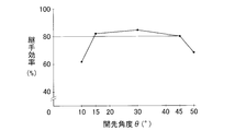
- ⁇ Test material -Aluminum alloy cast member: AC4CH-T5 (ISO Al-Si7Mg), thickness 8mm ⁇ Extensible member of aluminum alloy: 6N01-T5, thickness 3.5mm O Groove shape: FIG. However, the groove angle ⁇ , the slope height H, and the route interval L were variables.
- ⁇ Welding conditions • Type: MIG welding • Filler rod: A5356WY equivalent • Current: 230A ⁇ Rotation angle: 75 ° ⁇ Advance angle: 15 ° ⁇ Welding speed: 70 cm / min
- ⁇ 30 ° was the best.
- the required joint efficiency is said to be 70%, but when evaluated at 80% with a 10% margin, the groove angle ⁇ is in the range of 15 ° to 45 °.
- HT Verification of difference in outer surface
- the horizontal axis in FIG. 5 is the outer surface difference (HT), and T is 3.5 mm (constant), so the outer surface difference is 0, H is 3.5 mm, the outer surface difference is 1 mm, and H is 4.5 mm.
- the difference between the outer surfaces is 2 mm and the H is 5.5 mm.
- a test piece was cut out from the obtained joint, and a tensile test was performed. For relative comparison, the tensile strength when the outer surface difference (HT) was 0 was 1.0, and the outer surface difference was 1.13 times when the outer surface difference was 1 mm, and 1.03 times when the outer surface difference was 2 mm. .
- ⁇ Verification of route interval L Gap G: In FIG. 2, the gap (gap) between the upper surface of the insertion portion 13 and the lower surface of the expanding member 12 has been set to 0, but here, two types of 0 mm and 1 mm are tested.
- ⁇ Slope height H 4.5 mm
- Thickness T of extension member 3.5mm
- ⁇ Groove angle ⁇ 30 ° Welding was performed under the above conditions, and the joint efficiency was determined for the resulting joint. The results are shown in FIG.
- the solid line indicates the case where the gap is 0, and the broken line indicates the case where the gap is 1 mm. Assuming that the required joint efficiency is 70%, the solid line indicates that the joint efficiency exceeds 70% if the route interval is 1.0 (the thickness of the expanded member is 1.0) or more. In FIG. 1, in order to easily insert the cast member 11 into the extending member 12, a gap of 0.5 to 1.0 mm is desired.
- the gap is 1.0 mm, as shown by the broken line, the joint efficiency is deteriorated and becomes less than 70% at 1.7 on the horizontal axis scale. From the above, the points a to b shown in the figure, that is, the root interval of (1.0 to 1.7) times the thickness of the extension member is recommended.
- the sub-frame 20 as a structure includes a front cross portion 21 and a rear cross portion 22 that extend in the width direction of the vehicle, front arm portions 23 and 24 that extend from both ends of the front cross portion 21, and a rear
- the rear arm portions 25 and 26 extend from both ends of the cross portion 22, and the left long portion 27 and the right long portion 28 that extend in the longitudinal direction of the vehicle and connect the front cross portion 21 and the rear cross portion 22.
- the front cross part 21 and the rear cross part 22, the front arm parts 23 and 24, the rear arm parts 25 and 26, the left longitudinal part 27, and the right longitudinal part 28 are cast members made of an aluminum alloy.
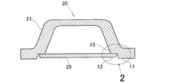
- the front cross portion 21 has a channel shape opened downward. If it is a channel, there are many hollow parts and weight reduction can be achieved. On the other hand, the strength of the hollow cross section is lower than that of the solid cross section. In terms of strength, the bending stress at the center of the vehicle width is maximized. As a countermeasure, a reinforcing plate 29 is added to the vehicle width center portion of the front cross portion 21 as shown in FIG.
- the reinforcing plate 29 is a spread member made of one of aluminum and aluminum alloy. As shown in FIG. 8, the reinforcing plate 29 is applied to and welded to the front cross portion 21 so as to close the lower opening of the front cross portion 21 that is a cast member. That is, the end portion of the reinforcing plate 29 has the joint shape shown in FIG. 2 and is joined to the front cross portion 21.
- the weld joint of the present invention is suitable for a vehicle subframe, but may be applied to other welded structures.
- the welded joint of the present invention is suitable for a vehicle subframe.
Landscapes
- Engineering & Computer Science (AREA)
- Mechanical Engineering (AREA)
- Physics & Mathematics (AREA)
- Plasma & Fusion (AREA)
- Chemical & Material Sciences (AREA)
- Combustion & Propulsion (AREA)
- Transportation (AREA)
- Materials Engineering (AREA)
- Arc Welding In General (AREA)
- Butt Welding And Welding Of Specific Article (AREA)
- Body Structure For Vehicles (AREA)
Abstract
Description
蓋体は、全周がフレーム本体に接合される。いわゆる、全周溶接がなされるため、溶接長さが著しく長くなり、溶接コストが嵩む。加えて、溶接歪が大きくなり、歪を矯正する矯正コストが嵩む。そのため、特許文献1に記載された溶接構造物では、製造費が嵩む。
図9は従来の溶接構造物の一例を示す図であり、溶接構造物としてのサブフレーム100は、右側鋳造部材101と左側鋳造部材102と、角筒状の展伸部材103、104とを、4個の溶接部105で繋ぐことにより得られる矩形フレームである。
車両の軽量化の一環として、鋳造部材101、102はアルミニウム合金の鋳造部材とされ、展伸部材103、104はアルミニウム又はアルミニウム合金の展伸部材が採用される。
また、鋳造部材101は、鋳物であるから、不可避的にガスを内包している。その上、アルミニウム合金鋳物の融点は、アルミニウム合金展伸部材の融点より低い。
これらの要因が重なると、ビード107におけるのど厚108の確保が難しくなる。のど厚108が不足すると、溶接部105の強度不足や品質低下という不具合が起こる。
図1に示されるように、溶接施工前の構造物10は、アルミニウム合金の鋳造部材11と、アルミニウム又はアルミニウム合金の展伸部材12とからなる。これらの材料11、12同士は、後にミグ溶接により一体化される。
図2に示されるように、鋳造部材11の端部は、厚さ方向に高さHだけ上面11aから下面11bに向かって斜めに切り込まれている。さらに、斜面14の下端から端面まで下面11bに平行に切断されている。結果、鋳造部材11の端部に、展伸部材12の下面に沿って延びる差込み部13が形成される。
展伸部材12は、開先の底が展伸部材12の厚さTの(1.0~1.7)倍のルート間隔Lが得られるように、斜面14から離されている。
斜面14の高さHは、図に示されるように展伸部材12の厚さTより、若干大きくした。
このビード15の評価を、実験で確かめる。
本発明に係る実験例を以下に述べる。なお、本発明は実験例に限定されるものではない。
・アルミニウム合金の鋳造部材:AC4CH-T5(ISO Al-Si7Mg)、厚さ8mm
・アルミニウム合金の展伸部材:6N01-T5、厚さ3.5mm
○開先形状:図2。ただし、開先角度θ、斜面の高さH、ルート間隔Lは変数とした。
○溶接条件:
・種類:ミグ溶接
・溶加棒:A5356WY相当品
・電流:230A
・回転角:75°
・前進角:15°
・溶接速度:70cm/分
・斜面の高さH:4.5mm
・ルート間隔L:5mm
・開先角度θ:10°、15°、30°、45°、50°
の条件で溶接を実施し、得られた継手について、継手効率を求めた。結果を図4に示す。
図2に示される展伸部材12の厚さTと、斜面14の高さHとの関係を調べた。結果を図5に示す。
図5の横軸は、外面差(H-T)であり、Tが3.5mm(一定)であるから、外面差が0でHは3.5mm、外面差が1mmでHは4.5mm、外面差が2mmでHが5.5mmとなる。得られた継手からテストピースを切出し、引張試験を実施した。相対比較をするために、外面差(H-T)が0での引張強さを1.0とした、外面差が1mmでは1.13倍、外面差が2mmでは1.03倍であった。
・ギャップG:図2において、差込み部13の上面と展伸部材12の下面との間の隙間(ギャップ)は、0に設定してきたが、ここでは、0mmと1mmの2種類を実験する。
・斜面の高さH:4.5mm
・展伸部材の厚さT:3.5mm
・ルート間隔L:4mm(L/T=1.14)、5mm(L/T=1.42)、6mm(L/T=1.71)
・開先角度θ:30°
以上の条件で溶接を実施し、得られた継手について、継手効率を求めた。結果を図6に示す。
要求される継手効率を70%とすると、実線では、ルート間隔が1.0(展伸部材の厚さを1.0とした。)以上であれば、継手効率は70%を超える。
図1において展伸部材12に鋳造部材11を容易に差込むには、0.5~1.0mmの隙間が欲しい。
以上から、図中に示すa点~b点、すなわち、展伸部材の厚さの(1.0~1.7)倍のルート間隔が推奨される。
図7に示すように、構造物としてのサブフレーム20は、車両の幅方向に延びる前クロス部21及び後クロス部22と、前クロス部21の両端から延びる前アーム部23、24と、後クロス部22の両端から延びる後アーム部25、26と、車両の長手方向に延びて前クロス部21と後クロス部22とを繋ぐ左長手部27及び右長手部28とからなる。
対策として、図7に示すように前クロス部21の車幅中央部に補強板29を加える。
Claims (1)
- アルミニウム合金からなる鋳造部材の一端部に、アルミニウムとアルミニウム合金の一方からなる展伸部材の一端部を接合してなるアルミニウム合金部材の溶接継手であって、
前記鋳造部材は、前記鋳造部材の上面から下面に向かって前記鋳造部材の厚さの途中まで延びる斜面と、前記斜面の下端から前記鋳造部材の先端に向かって前記展伸部材の下面に沿って延びる差込み部と、を有しており、
前記斜面下端から前記展伸部材の一端部の端面までの距離は、前記展伸部材の厚さの1.0~1.7倍に設定されており、
前記斜面は、前記展伸部材の一端部の端面との間の開先の角度が15°~45°になるよう傾斜しており、
前記開先に溶接が施され、もって前記差込み部が裏当て金として作用することを特徴とするアルミニウム合金部材の溶接継手。
Priority Applications (4)
| Application Number | Priority Date | Filing Date | Title |
|---|---|---|---|
| CN2010800167391A CN102395443A (zh) | 2009-04-15 | 2010-04-15 | 铝合金部件的焊接接头 |
| US13/264,617 US20120027506A1 (en) | 2009-04-15 | 2010-04-15 | Weld joint of aluminum alloy member |
| EP10764507A EP2420342A1 (en) | 2009-04-15 | 2010-04-15 | Weld joint of aluminum alloy member |
| JP2011509349A JPWO2010119925A1 (ja) | 2009-04-15 | 2010-04-15 | アルミニウム合金部材の溶接継手 |
Applications Claiming Priority (2)
| Application Number | Priority Date | Filing Date | Title |
|---|---|---|---|
| JP2009099265 | 2009-04-15 | ||
| JP2009-099265 | 2009-04-15 |
Publications (1)
| Publication Number | Publication Date |
|---|---|
| WO2010119925A1 true WO2010119925A1 (ja) | 2010-10-21 |
Family
ID=42982582
Family Applications (1)
| Application Number | Title | Priority Date | Filing Date |
|---|---|---|---|
| PCT/JP2010/056766 Ceased WO2010119925A1 (ja) | 2009-04-15 | 2010-04-15 | アルミニウム合金部材の溶接継手 |
Country Status (5)
| Country | Link |
|---|---|
| US (1) | US20120027506A1 (ja) |
| EP (1) | EP2420342A1 (ja) |
| JP (1) | JPWO2010119925A1 (ja) |
| CN (1) | CN102395443A (ja) |
| WO (1) | WO2010119925A1 (ja) |
Families Citing this family (12)
| Publication number | Priority date | Publication date | Assignee | Title |
|---|---|---|---|---|
| US20130266818A1 (en) | 2012-04-10 | 2013-10-10 | Hamilton Sundstrand Corporation | Article including a weld joint |
| CN103615627B (zh) * | 2013-11-28 | 2015-09-16 | 攀钢集团攀枝花钢钒有限公司 | 电站锅炉省煤器泄漏处理方法 |
| JP6730927B2 (ja) * | 2014-01-24 | 2020-07-29 | エレクトリック パワー リサーチ インスチテュート インコーポレイテッド | 段付き設計の溶接継手用作製物 |
| JP2016198811A (ja) * | 2015-04-14 | 2016-12-01 | ジャパンマリンユナイテッド株式会社 | 極厚鋼板の突合せ溶接構造と突合せ溶接方法 |
| CN104858535A (zh) * | 2015-05-18 | 2015-08-26 | 上海交通大学 | 一种提高搭接接头强度的连接方法 |
| JP6709638B2 (ja) * | 2016-03-10 | 2020-06-17 | 日立造船株式会社 | 鋼管構造体における鋼管と継手との溶接方法 |
| CN106514029B (zh) * | 2016-12-20 | 2019-05-14 | 东方电气集团东方锅炉股份有限公司 | 长管端部堆焊的方法 |
| CN107127452A (zh) * | 2017-06-27 | 2017-09-05 | 东莞市纳百川电子科技有限公司 | 一种金属焊接工艺 |
| DE102017119677A1 (de) * | 2017-08-28 | 2019-02-28 | Doduco Solutions Gmbh | Verfahren zum Herstellen eines Überlapp-Verbundmaterials aus Blech |
| EP3838722B1 (de) * | 2019-12-20 | 2022-03-16 | Autotech Engineering Deutschland GmbH | Hilfsrahmen für ein kraftfahrzeug |
| CN114473275A (zh) * | 2021-12-31 | 2022-05-13 | 上海集度汽车有限公司 | 车架、其焊接接头结构与制造方法 |
| WO2026057313A1 (en) | 2024-09-13 | 2026-03-19 | Autotech Engineering S.L. | Chassis component for a motor vehicle, in particular in the form of a subframe, and method of manufacturing such a chassis component |
Citations (9)
| Publication number | Priority date | Publication date | Assignee | Title |
|---|---|---|---|---|
| JPS5296941A (en) * | 1976-02-10 | 1977-08-15 | Mitsubishi Electric Corp | Method of welding thick plates on mig welding |
| JPS56119667A (en) * | 1980-02-26 | 1981-09-19 | Nippon Steel Corp | Method for prevention of formation of weld defects |
| JPS5736093A (ja) * | 1980-08-13 | 1982-02-26 | Tokushu Piston Seisakusho:Kk | Puranjanoseizohoho |
| JPS6064777A (ja) * | 1983-09-16 | 1985-04-13 | Daihatsu Motor Co Ltd | アルミダイカスト製部材にアルミ展伸材製部材を溶接する方法 |
| JPS6376769A (ja) * | 1986-09-19 | 1988-04-07 | Suzuki Motor Co Ltd | オ−トバイのフレ−ム溶接構造 |
| JPH07303968A (ja) * | 1994-05-10 | 1995-11-21 | Nippon Light Metal Co Ltd | アルミニウム駆動軸 |
| JPH10258765A (ja) * | 1997-03-18 | 1998-09-29 | Kobe Steel Ltd | 自動車構造部材用継手構造 |
| JP2004210013A (ja) | 2002-12-27 | 2004-07-29 | Showa Denko Kk | 車両用中空フレーム及び車両 |
| JP2007283348A (ja) * | 2006-04-14 | 2007-11-01 | Komatsu Ltd | 溶接方法およびこれにより溶接されたリングギア部材 |
Family Cites Families (8)
| Publication number | Priority date | Publication date | Assignee | Title |
|---|---|---|---|---|
| US2324335A (en) * | 1940-12-20 | 1943-07-13 | Taylor Edward Hall | Pipe joint |
| US2895747A (en) * | 1955-05-31 | 1959-07-21 | Standard Oil Co | Welded aluminum coated tubular member and method of making same |
| US3195229A (en) * | 1962-05-21 | 1965-07-20 | Foster Wheeler Corp | Method of butt welding metal tubes |
| US3790120A (en) * | 1971-12-13 | 1974-02-05 | Flexicore Co | Composite slab casting form |
| US4182950A (en) * | 1973-10-11 | 1980-01-08 | Boros Lawrence A | Deep fill welding joint configuration and welding method |
| JP3402550B2 (ja) * | 1996-01-30 | 2003-05-06 | 日産自動車株式会社 | 溶接継手用開先 |
| FR2807682A1 (fr) * | 2000-04-17 | 2001-10-19 | Soudure Autogene Francaise | Preparation et soudage mig ou mag de pieces tubulaires |
| JP4786378B2 (ja) * | 2006-03-14 | 2011-10-05 | 三菱重工業株式会社 | 配管継手構造 |
-
2010
- 2010-04-15 EP EP10764507A patent/EP2420342A1/en not_active Withdrawn
- 2010-04-15 WO PCT/JP2010/056766 patent/WO2010119925A1/ja not_active Ceased
- 2010-04-15 US US13/264,617 patent/US20120027506A1/en not_active Abandoned
- 2010-04-15 JP JP2011509349A patent/JPWO2010119925A1/ja not_active Withdrawn
- 2010-04-15 CN CN2010800167391A patent/CN102395443A/zh not_active Withdrawn
Patent Citations (9)
| Publication number | Priority date | Publication date | Assignee | Title |
|---|---|---|---|---|
| JPS5296941A (en) * | 1976-02-10 | 1977-08-15 | Mitsubishi Electric Corp | Method of welding thick plates on mig welding |
| JPS56119667A (en) * | 1980-02-26 | 1981-09-19 | Nippon Steel Corp | Method for prevention of formation of weld defects |
| JPS5736093A (ja) * | 1980-08-13 | 1982-02-26 | Tokushu Piston Seisakusho:Kk | Puranjanoseizohoho |
| JPS6064777A (ja) * | 1983-09-16 | 1985-04-13 | Daihatsu Motor Co Ltd | アルミダイカスト製部材にアルミ展伸材製部材を溶接する方法 |
| JPS6376769A (ja) * | 1986-09-19 | 1988-04-07 | Suzuki Motor Co Ltd | オ−トバイのフレ−ム溶接構造 |
| JPH07303968A (ja) * | 1994-05-10 | 1995-11-21 | Nippon Light Metal Co Ltd | アルミニウム駆動軸 |
| JPH10258765A (ja) * | 1997-03-18 | 1998-09-29 | Kobe Steel Ltd | 自動車構造部材用継手構造 |
| JP2004210013A (ja) | 2002-12-27 | 2004-07-29 | Showa Denko Kk | 車両用中空フレーム及び車両 |
| JP2007283348A (ja) * | 2006-04-14 | 2007-11-01 | Komatsu Ltd | 溶接方法およびこれにより溶接されたリングギア部材 |
Also Published As
| Publication number | Publication date |
|---|---|
| EP2420342A1 (en) | 2012-02-22 |
| JPWO2010119925A1 (ja) | 2012-10-22 |
| US20120027506A1 (en) | 2012-02-02 |
| CN102395443A (zh) | 2012-03-28 |
Similar Documents
| Publication | Publication Date | Title |
|---|---|---|
| WO2010119925A1 (ja) | アルミニウム合金部材の溶接継手 | |
| JP5435187B2 (ja) | 鋼床版及び鋼床版の製造方法 | |
| WO2009110256A1 (ja) | ナックルブラケット | |
| JP6344478B2 (ja) | 溶接構造部材及びその製造方法 | |
| CN108136528A (zh) | 角焊方法和角焊接头 | |
| CN109131566A (zh) | 汽车横梁与纵梁的搭接结构及横、纵梁的焊接方法 | |
| JP4112969B2 (ja) | ゴルフクラブヘッド | |
| JP2012206156A5 (ja) | ||
| JP2013139047A (ja) | 鋼材の溶接接合部 | |
| JP5292993B2 (ja) | 鋼床版 | |
| CN101506437A (zh) | 桥墩的角接头结构及角接头施工方法 | |
| CN101505902A (zh) | 加强板及加强板的制造方法 | |
| JP2006224137A (ja) | 補剛板及び補剛板の製造方法 | |
| JP5979859B2 (ja) | バックシールド溶接方法 | |
| JP2008018458A (ja) | 補剛板及び補剛板の製造方法 | |
| JP2005029155A (ja) | トーションビーム式アクスルのための、鋼から成るクロスストラット | |
| US8474511B2 (en) | Process for producing a twist-beam axle in a hybrid construction | |
| JP2007167924A (ja) | 鉄道車両の構体材溶接接合方法とそれに用いる継手構造 | |
| JP5900189B2 (ja) | 鋼材の溶接接合部および溶接接合部の形成方法 | |
| JP4560288B2 (ja) | 溶接方法 | |
| JP2007062538A (ja) | 車両用車軸ケースの溶接構造 | |
| JP7633600B2 (ja) | 溶接継手構造 | |
| JP2024007883A (ja) | 溶接構造物の補強方法 | |
| JP4530154B2 (ja) | 橋脚の角継手構造及び角継手工法 | |
| KR20140134385A (ko) | 맞대기 이음 용접용 탭 피스 |
Legal Events
| Date | Code | Title | Description |
|---|---|---|---|
| WWE | Wipo information: entry into national phase |
Ref document number: 201080016739.1 Country of ref document: CN |
|
| 121 | Ep: the epo has been informed by wipo that ep was designated in this application |
Ref document number: 10764507 Country of ref document: EP Kind code of ref document: A1 |
|
| WWE | Wipo information: entry into national phase |
Ref document number: 2011509349 Country of ref document: JP |
|
| WWE | Wipo information: entry into national phase |
Ref document number: 13264617 Country of ref document: US |
|
| NENP | Non-entry into the national phase |
Ref country code: DE |
|
| WWE | Wipo information: entry into national phase |
Ref document number: 2010764507 Country of ref document: EP |