WO2010125863A1 - 車両の荷物保持装置 - Google Patents
車両の荷物保持装置 Download PDFInfo
- Publication number
- WO2010125863A1 WO2010125863A1 PCT/JP2010/054171 JP2010054171W WO2010125863A1 WO 2010125863 A1 WO2010125863 A1 WO 2010125863A1 JP 2010054171 W JP2010054171 W JP 2010054171W WO 2010125863 A1 WO2010125863 A1 WO 2010125863A1
- Authority
- WO
- WIPO (PCT)
- Prior art keywords
- holding device
- lock
- vehicle
- luggage holding
- pedestal
- Prior art date
- Legal status (The legal status is an assumption and is not a legal conclusion. Google has not performed a legal analysis and makes no representation as to the accuracy of the status listed.)
- Ceased
Links
Images


Classifications
-
- B—PERFORMING OPERATIONS; TRANSPORTING
- B60—VEHICLES IN GENERAL
- B60P—VEHICLES ADAPTED FOR LOAD TRANSPORTATION OR TO TRANSPORT, TO CARRY, OR TO COMPRISE SPECIAL LOADS OR OBJECTS
- B60P7/00—Securing or covering of load on vehicles
- B60P7/06—Securing of load
-
- B—PERFORMING OPERATIONS; TRANSPORTING
- B60—VEHICLES IN GENERAL
- B60P—VEHICLES ADAPTED FOR LOAD TRANSPORTATION OR TO TRANSPORT, TO CARRY, OR TO COMPRISE SPECIAL LOADS OR OBJECTS
- B60P7/00—Securing or covering of load on vehicles
- B60P7/06—Securing of load
- B60P7/08—Securing to the vehicle floor or sides
- B60P7/0807—Attachment points
- B60P7/0815—Attachment rails or trellis
-
- B—PERFORMING OPERATIONS; TRANSPORTING
- B60—VEHICLES IN GENERAL
- B60P—VEHICLES ADAPTED FOR LOAD TRANSPORTATION OR TO TRANSPORT, TO CARRY, OR TO COMPRISE SPECIAL LOADS OR OBJECTS
- B60P7/00—Securing or covering of load on vehicles
- B60P7/06—Securing of load
- B60P7/08—Securing to the vehicle floor or sides
Definitions
- the present invention relates to a luggage holding device for holding luggage on a vehicle floor or the like.
- Patent Document 1 Conventionally, as this type of luggage holding device, there is one disclosed in Patent Document 1.
- Patent Document 1 discloses a luggage holding device that is provided with a locking member that can be moved to a guide rail and can be fixed at an arbitrary position, and a side part such as a net member is detachably attached to the locking member to hold the luggage. is doing.
- the locking member has a pair of washers that sandwich the upper wall of the guide rail. And a locking member becomes movable by loosening the screw member screwed together with a pair of washer members, and a locking member is locked by tightening a screw member.
- multi-purpose vehicles such as three-row seat cars are popular, and usage of the vehicle floor according to various situations has been proposed.
- the luggage is held in the luggage compartment according to the front and rear positions of the seats, or between the seats. Is requested to be able to hold luggage.
- the luggage holding device may be easily attached to and detached from the guide rail.
- an object of the present invention is to make it possible to easily attach and detach the luggage holding device to / from the guide rail.
- a vehicle luggage holding device that can be attached to a guide rail having a pair of guide pieces facing each other through a slit, A pedestal having a contact portion that can be disposed so as to straddle the guide piece, a locking portion provided on the pedestal portion for holding a load, and one end protruding from the contact portion side A shaft body supported by the pedestal portion so as to be movable in the axial direction so that the other end portion protrudes from the side opposite to the contact portion, and the width dimension is smaller than the width dimension of the slit.
- the lock is formed in an elongated shape larger than the width of the slit, and is supported by one end of the shaft body so as to be movable toward and away from the pedestal. Support the other end to change the posture And a lock lever capable of changing a posture between a lock posture for drawing the lock portion toward the pedestal portion and a lock release posture for allowing the lock portion to be separated from the pedestal portion. is there.
- the vehicle luggage holding device is the vehicle luggage holding device according to the first aspect, and further includes a separation elastic member that urges the lock portion in a direction of separating from the pedestal portion. Is.
- the vehicle luggage holding device is the vehicle luggage holding device according to the first or second aspect, wherein a leg piece movably disposed in the slit is provided on the pedestal portion. It is provided.
- the vehicle luggage holding device is the vehicle luggage holding device according to the third aspect, wherein the leg piece is formed in a positioning recess formed facing the slit in the guide rail. A positioning extension portion that can be engaged is formed.
- a vehicle luggage holding device is the vehicle luggage holding device according to any one of the first to fourth aspects, wherein the lock portion rotates at one end of the shaft body.
- the other end portion of the shaft body is rotatably supported by the pedestal portion, and the lock portion is rotated around the axis of the shaft body through the shaft body by a rotation operation of the lock lever. Is.
- a vehicle luggage holding device is the vehicle luggage holding device according to any one of the first to fifth aspects, wherein the locking portion is supported on the pedestal portion so that the posture thereof can be changed.
- a pair of bearing portions projecting, and the lock lever is disposed between the pair of bearing portions in the locking posture.
- a vehicle luggage holding device is the vehicle luggage holding device according to any one of the first to sixth aspects, wherein the locking portion is supported on the pedestal portion so that the posture thereof can be changed.
- a pair of bearing portions projecting, and a ring member is interposed between each of the pair of bearing portions and both end portions where the locking portions are supported by the bearing portion.
- a luggage holding device for a vehicle according to an eighth aspect is the luggage holding device for a vehicle according to any one of the first to seventh aspects, and when the posture of the lock lever is changed to a standing posture on the pedestal portion, A lever receiving portion for receiving the lock lever is provided.
- the vehicle luggage holding device according to any one of the first to eighth vehicles, wherein the pedestal portion is provided with a lock state display portion that indicates a posture of the lock lever. It is what has been.
- the vehicle luggage holding device is any one of the first to ninth vehicle luggage holding devices, wherein the pedestal portion is made of zinc.
- a vehicle luggage holding device is any one of the first to tenth vehicle luggage holding devices, wherein the shaft body is interposed via an interposed elastic member by changing the posture of the lock lever. Then, the lock part is pulled toward the pedestal part side.
- the vehicle luggage holding device is the vehicle luggage holding device according to the eleventh aspect, wherein the interposition elastic body has a plurality of disc springs arranged in series.
- the width of the lock portion is smaller than the width of the slit and the length is larger than the width of the slit. Can be easily inserted into and removed from the slit in between.
- the lock part is disposed in the guide rail through the slit and the position of the lock part is changed from the unlocked position to the locked position, the lock part is drawn toward the pedestal part, and the contact part of the pedestal A pair of guide pieces are sandwiched between the door and the lock portion, and the load holding device can be fixed to a fixed position with respect to the guide rail.
- maintenance apparatus can be removed from a guide rail. Therefore, the luggage holding device can be easily attached to and detached from the guide rail.
- the lock portion in a state in which the lock lever is in the unlocking posture, the lock portion is urged to a position more securely separated from the pedestal portion by the separation elastic member, and between the pedestal portion and the lock portion. A large gap is formed. For this reason, a pair of guide pieces can be easily disposed between the pedestal portion and the lock portion, and the load holding device can be attached smoothly.
- the posture of the pedestal portion can be made constant with respect to the extending direction of the slit.
- the load holding device can be more reliably fixed at a fixed position with respect to the extending direction of the guide rail.
- the lock portion in a state where the pedestal portion is in a fixed posture with respect to the extending direction of the slit, the lock portion can be inserted into and removed from the slit by rotating the lock lever.
- the state can be switched to a state in which the pair of guide pieces are brought into contact with each other.
- the lock lever is disposed between the pair of bearing portions in the locked posture, inadvertent unlocking is suppressed.
- the ring member is interposed between each of the pair of bearing portions and both end portions where the locking portion is supported by the bearing portion, the operation force for changing the position of the locking portion. Stabilization and rattling of the locking portion can be suppressed.
- the lock lever can be prevented from further falling to the pedestal part side after the standing posture is changed, and pinching between the lock lever and the pedestal part can be prevented.
- the lock state display unit can grasp the lock state of the luggage holding device according to the posture of the lock lever.
- the pedestal portion side is damaged, so that the other member can be prevented from being damaged.
- the shaft body draws the lock portion toward the pedestal portion via the interposed elastic member, it is easy to ensure the holding force even if the thickness of the pair of guide pieces is uneven.
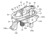
- FIG. 1 is a perspective view showing a luggage holding device for a vehicle according to an embodiment. It is a side view which shows the luggage holding apparatus same as the above. It is a top view which shows a luggage holding apparatus same as the above. It is a bottom view which shows a luggage holding apparatus same as the above. It is a disassembled perspective view which shows a luggage holding apparatus same as the above.
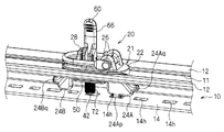
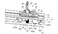
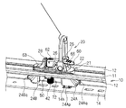
- FIG. 4 is a partial cross-sectional view taken along line VI-VI in FIG. 3. It is a partial side view which shows an interposed elastic member. It is a partially broken perspective view which shows the operation
- FIG. 1 is a perspective view showing the load holding device 20
- FIG. 2 is a side view showing the load holding device 20
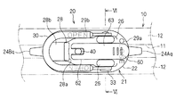
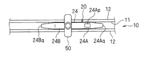
- FIG. 3 is a plan view showing the load holding device 20
- FIG. 5 is an exploded perspective view showing the luggage holding device 20
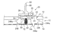
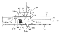
- FIG. 6 is a partial sectional view taken along line VI-VI in FIG.
- the luggage holding device 20 is configured to be detachably attached to the guide rail 10 fixed to the vehicle. Then, in a state where the baggage holding device 20 is mounted and fixed at a fixed position in the extending direction of the guide rail 10, a net, a rope (including an extendable one) for fixing the baggage, or an end portion thereof A hook or the like attached to the hook is locked so as to be hooked on the load holding device 20.
- the guide rail 10 is a rail laid at a predetermined position of the vehicle, and here, the guide rail 10 is laid on the vehicle interior floor along the front-rear direction to support the seat so as to be movable back and forth. This will be explained with an example.
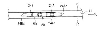
- the guide rail 10 is formed in a substantially rectangular tube shape having a pair of guide pieces 12 opposed to each other via a slit 11 on the upper side.
- the edge portion on the slit 11 side of the guide piece 12 is folded back toward the inside of the guide rail 10, and therefore the end edge portion of the guide piece 12 is based on the thickness of the plate material forming the guide piece 12 itself. Is also thicker.
- the sheet guide member is disposed in the guide rail 10 through the slit 11, and is supported so as to be movable along the guide rail 10. Further, in the guide rail 10, a plurality of positioning recesses 14 h are formed along the extending direction of the slit 11 at intervals in the bottom portion 14 facing the slit 11 (see FIG. 8). Then, the positioning restriction piece of the guide member is fitted into one of the plurality of positioning recesses 14h, so that the positioning of the guide member, that is, the sheet is fixed.
- the luggage holding device 20 includes a pedestal portion 21, a locking portion 30, a shaft body 40, a lock portion 50, and a lock lever 60.
- a net, a rope, a hook, or the like for fixing the load is locked by being hooked to the locking portion 30 attached to the pedestal portion 21.
- the lock portion 50 is supported so as to be movable toward and away from the base portion 21 via the shaft body 40. Then, in a state where the lock portion 50 is disposed in the guide rail 10, a pair of movements between the pedestal portion 21 and the lock portion 50 are performed by moving the lock portion 50 closer to the pedestal portion 21 by operating the lock lever 60.
- the guide piece 12 is sandwiched so that the luggage holding device 20 is fixed to the guide rail 10 at a fixed position.
- the pedestal portion 21 includes a pedestal main body portion 22 having a contact portion 23 that can be disposed so as to straddle the pair of guide pieces 12.
- the pedestal main body 22 is formed in a substantially oval shape in plan view, and the dimension in the short axis direction is formed to be larger than the width of the slit 11.
- One main surface side of both long side portions of the pedestal main body portion 22 is the abutting portion 23 that can abut against the pair of guide pieces 12 in a sliding manner.
- leg pieces 24 that are movably disposed in the slit 11 are formed in a protruding shape. More specifically, a plate-like leg piece 24 extending along the major axis direction is formed at a substantially central portion in the width direction of one main surface of the pedestal main body 22. The thickness dimension of the leg piece 24 (dimension in the minor axis direction of the pedestal portion 21) is smaller than the width dimension of the slit 11 (in this case, the posture of the leg piece 24 in the slit 11 can be kept constant). Slightly smaller).
- projecting leg pieces 24 ⁇ / b> A and 24 ⁇ / b> B that project larger than the middle part in the longitudinal direction are formed.
- the projecting dimensions of the projecting leg pieces 24 ⁇ / b> A and 24 ⁇ / b> B are formed so as to reach the position immediately before the bottom 14 in a state in which the abutting portion 23 is in contact with the pair of guide pieces 12.
- the positioning recess 14h formed in the bottom portion 14 is formed at the distal end portion of one leg piece 24A so as to extend beyond the bottom portion 14 in a state where the contact portion 23 is in contact with the pair of guide pieces 12.
- a positioning extension 24Ap that can be disposed inside is formed.
- the long axis of the pedestal main body 22 is brought into sliding contact with the outward surfaces of the pair of guide pieces 12 by arranging the leg pieces 24 in the slit 11.
- the pedestal 21 is movable with respect to the guide rail 10 in a fixed posture in which the direction is arranged along the extending direction of the slit 11.
- the positioning extension portion 24Ap of the one leg piece 24A is locked so as to be fitted in the positioning recess 14h formed in the bottom portion 14, so that the base portion 21 extends in the extending direction with respect to the guide rail 10. Positioned.
- the protrusion dimension of the longitudinal direction intermediate part of the said leg piece 24 is smaller than the thickness dimension of a pair of guide piece 12 which pinches
- the pair of guide pieces 50 is sandwiched by 50.
- extending portions 24Aq and 24Bq that protrude outward in the major axis direction of the pedestal main body portion 22 are formed in the protruding leg pieces 24A and 24B.
- the extension portions 24Aq and 24Bq are connected to the guide member before the pedestal main body 22 comes into contact with a relatively weak portion such as a resin portion of the guide member. It comes into contact with a relatively strong portion such as a metal portion.
- the pedestal portion 21 is preferably made of zinc.
- the manufacturing method of the base part 21 is die-casting or cutting, for example. The merit by forming the base part 21 with zinc is mentioned later.
- the locking portion 30 is a member for holding a load by locking and fixing a net, a rope for fixing the load, or a hook or the like attached to the end portion thereof.
- the metal rod is a member formed in a substantially U shape. This latching
- locking part 30 is attached to the base main-body part 22 with the following structure.
- a pair of bearing portions 26 project from one end portion of the surface of the pedestal main body portion 22 on the opposite side of the leg piece 24 along the short axis direction of the pedestal main body portion 22.
- a pair of bearing part 26 is connected via the bearing relay part 27 protrudingly provided by the base body part 22 (refer FIG.5 and FIG.6).
- the bearing relay portion 27 has a smaller projecting dimension than the bearing portion 26, and an end portion of a lock lever 60 described later can be disposed between the bearing relay portion 27 and the pair of bearing portions 26.
- a through hole 27h is formed so as to penetrate the pair of bearing portions 26 and the bearing relay portion 27 along the short axis direction of the pedestal main body portion 22 (see FIGS. 5 and 6).
- An annular groove 27ha is formed on the outward faces of the pair of bearing portions 26 and around the openings at both ends of the through hole 27h.
- An O-ring 34 as a ring member made of rubber, soft resin or the like is disposed in the annular groove 27ha.
- shaft support holes 30h are formed at both ends of the locking portion 30 (see FIGS. 5 and 6).
- the O-ring 34 is disposed in the annular groove 27ha, and the head 32 is provided at one end in a state where the shaft support holes 30h and the through holes 27h at both ends of the locking portion 30 are disposed on the same straight line.
- the pin member 33 having the above is inserted into the shaft support hole 30h and the through hole 27h. Then, the pin member 33 is secured and secured by crushing the other end of the pin member 33 protruding from the through hole 27h and the shaft support hole 30h.
- both end portions of the locking portion 30 are rotatably supported by the pair of bearing portions 26 via the pin member 33.
- locking part 30 is supported with respect to the base main-body part 22 so that an attitude
- the O-ring 34 is interposed between the pair of bearing portions 26 and both end portions of the locking portion 30 in a compressed manner.
- the O-ring 34 is interposed between the bearing portion 26 and both ends of the locking portion 30 in a compressed manner, direct contact between the bearing portion 26 and the locking portion 30 is suppressed, The operation force when changing the posture of the portion 30 is stabilized, and rattling of the locking portion 30 with respect to the bearing portion 26 is suppressed.
- the locking portion 30 Since the rotation shaft of the locking portion 30 and the rotation shaft of the lock lever 60 described later are set separately, the locking portion 30 is positioned by locking a member for fixing the load to the locking portion 30. Even when the lock lever 60 is changed, the lock lever 60 itself is difficult to rotate and is not easily unlocked.
- the locking portion may be fixed at a fixed position and posture with respect to the pedestal portion.
- locking part may be formed in the substantially J-shaped hook shape.
- the shaft body 40 is formed as a long rod-shaped member, and a collar-shaped lock portion fixing portion 42 is formed at one end portion, and a support hole for supporting the lock lever 60 at the other end portion so that the posture can be changed. 41 is formed (see FIG. 5). Moreover, the cross-sectional shape of the part of the one end side in which the lock part 50 is inserted and hold
- the shaft body 40 is formed in a shape in which both side portions of a round bar are cut out in a planar shape.
- the shaft body 40 is supported so as to be movable with respect to the pedestal portion 21 as follows. That is, the through-hole 22h extends through the pedestal main body 22 at the substantially intermediate portion in the major axis direction of the pedestal main body 22 and more specifically at the substantially central portion of the pair of protruding leg pieces 24A and 24B. It is formed (see FIG. 5).
- the shaft body 40 is inserted into the through hole 22h of the pedestal main body portion 22 so that the one end portion protrudes from the contact portion 23 side and the other end portion protrudes from the opposite side of the contact portion 23. It is supported so as to be movable and rotatable along the direction.
- the lock part 50 is formed in a long plate shape, the width dimension is smaller than the width dimension of the slit 11, and the length dimension is larger than the width dimension of the slit 11.
- the lock portion 50 is configured by superimposing two plate members, but may be formed of a single plate material, and does not have to be a plate material but is a rod-shaped member. May be.
- a lock portion insertion hole 50h through which the non-circular cross-sectional shape portion of the shaft body 40 can be inserted is formed in a substantially central portion of the lock portion 50 (see FIG. 5).
- a non-circular cross-sectional shape portion of the shaft body 40 is inserted into the lock portion insertion hole 50h so as to be positioned between the base body portion 22 and the lock portion fixing portion 42. Accordingly, the lock portion 50 is supported by one end portion of the shaft body 40 so that the lock portion 50 can move toward and away from the base portion 21 and cannot rotate relative to the shaft body 40.
- a coil spring 70 as a separation elastic member is externally fitted to the shaft body 40 so as to be compressed between the pedestal main body portion 22 and the lock portion 50.
- the lock portion 50 is urged away from the pedestal main body portion 22 by the coil spring 70.
- the separating elastic member may be a disc spring, rubber or the like in addition to the coil spring.
- an interposed elastic member 72 is interposed between the lock part 50 and the lock part fixing part 42.
- the elastic force by the interposed elastic member 72 is set larger than the elastic force of the coil spring 70. Accordingly, when the shaft body 40 is pulled above the pedestal main body 22, the coil spring 70 is compressed and deformed, and the lock portion fixing portion 42 of the shaft body 40 moves the lock portion 50 via the intervening elastic member 72. It is designed to be pushed to the side.
- the interposed elastic member 72 is configured such that a plurality of disc springs 72 a are arranged in series while being externally fitted to the shaft body 40. Then, as will be described later, when the shaft body 40 is pulled to the side opposite to the contact portion 23 by changing the posture of the lock lever 60, the shaft body 40 causes the lock portion 50 to be pedestal via the intervening elastic member 72.
- the main body 22 is configured to be drawn.
- the amount of elastic deformation of the intervening elastic member 72 is made as large as possible, and within a relatively constrained space in the guide rail 10. A large force can be secured.
- the interposed elastic member 72 may be a plurality of disc springs, a single disc spring, a coil spring, rubber, or the like arranged in parallel.
- a lock lever 60 is supported at the other end of the shaft body 40 so that the posture can be changed. Then, by changing the posture of the lock lever 60 between the locked posture (see FIGS. 1 to 4) and the unlocked posture (see FIGS. 8 and 9), the shaft body 40 moves in the axial direction, The lock part 50 is moved toward and away from the base body part 22.
- the lock lever 60 includes a cam portion 62 that is rotatably supported on the other end portion of the shaft body 40 via a pin 68 (see FIG. 5), and an operation portion 66 that extends from the cam portion 62. And have.
- the cam portion 62 has a lock surface 63 and a lock release surface 64 that are continuous via a rounded corner portion 65.
- the lock surface 63 and the lock release surface 64 are substantially perpendicular to each other, and the distance between the rotation shaft of the cam portion 62 and the lock surface 63 is the distance between the rotation shaft of the cam portion 62 and the lock release surface 64. It is formed so as to be larger.
- the predetermined posture in which the corner portion 65 contacts the pedestal main body portion 22 is defined as a boundary posture, the posture in which the lock surface 63 is in contact with the pedestal main body portion 22, and the posture in which the lock release surface 64 is in contact with the pedestal main body portion 22.
- the posture is changed between In particular, it is possible to maintain both states in a fixed state, with the lock surface 63 in contact with the pedestal main body 22 and with the lock release surface 64 in contact with the pedestal main body 22.
- operation part 66 is formed so as to extend to the side opposite to the lock release surface 64.
- the lock release surface 64 contacts the pedestal main body 22, and the other end of the shaft body 40 is the pedestal main body 22. It is pushed into.
- the lock portion fixing portion 42 at one end of the shaft body 40 moves from the pedestal main body portion 22 in the separating direction, and the lock portion fixing portion 42 becomes movable from the pedestal main body portion 22 in the separating direction.
- the posture is changed from the above state so that the corner portion 65 comes into contact with the pedestal main body portion 22 and the operation portion 66 is tilted to lie on the pedestal main body portion 22, the lock surface 63 is moved to the pedestal main body portion.
- the lock lever 60 is in a state in which the lock portion 50 can be moved away from the pedestal main body portion 22 and the lock posture in which the lock portion 50 is attracted to the pedestal main body portion 22 (the posture of sleeping with respect to the pedestal main body portion 22)
- the posture can be changed between the unlocking posture (the posture standing up with respect to the base body 22).
- the pair of bearing portions 26 are disposed at positions where the operation portion 66 is sandwiched from both sides in a state where the lock lever 60 is in the locked posture as described above. Thereby, when the lock lever 60 is changed to the locked posture, the operation portion 66 is disposed between the pair of bearing portions 26.
- the lock lever 60 is supported at the other end of the shaft body 40 so as not to rotate in the axial direction of the shaft body 40, when the lock lever 60 is rotated around the axis of the shaft body 40, Along with the rotation, the lock part 50 rotates around the axis of the shaft body 40 via the shaft body 40.
- the pedestal main body 22 has a lever receiving portion for receiving the lock lever 60 when the lock lever 60 is changed from the sleeping position to the standing position, that is, when the lock lever 60 is changed from the locked position to the unlocked position.
- a stop 28 is erected. More specifically, the lever receiving portion 28 is erected on the opposite side of the shaft body 40 from the side on which the operation portion 66 extends in the locked posture (sleeping posture). The portion on the shaft body 40 side of the lever receiving portion 28 is formed on a flat surface 28a extending substantially perpendicular to the upper surface of the pedestal main body portion 22 (see FIGS. 2 and 13), and is locked from the locked posture.
- the lock lever 60 whose posture has been changed to the release posture is received by the plane 28a, and is prevented from changing its posture so as to be further tilted to the pedestal main body 22 side beyond the state. Thereby, after the lock lever 60 is changed to the standing posture, it is possible to prevent the lock lever 60 from further falling to the pedestal main body 22 side, and the pinching of any member or the like between the lock lever 60 and the pedestal main body 22 is suppressed. .
- a portion of the lever receiving portion 28 opposite to the shaft body 40 is formed on the curved concave surface 28b.
- the pedestal main body portion 22 is provided with lock state display portions 29a and 29b indicating the posture of the lock lever 60 (see FIGS. 1, 3 and 5).
- the lock of the pedestal main body 22 formed on the surface opposite to the abutting portion 23 and having a concavo-convex shape such as engraving on the outer portion of the pair of bearing portions 26 indicating the locked state.
- a status display section 29a is attached.
- a lock state display portion 29b is formed on the surface of the pedestal main body portion 22 opposite to the contact portion 23 and has a concavo-convex shape with “OPEN” indicating the unlocked state on both side portions of the shaft body 40. It is attached.
- the user of the luggage holding device 20 can grasp the locked state of the luggage holding device 20 and the operation direction of the lock lever 60 when performing the attachment / detachment work by looking at the lock state display portions 29a and 29b. ing.
- the structure which attaches the lock state display parts 29a and 29b is not restricted to the said example.
- only one of the locked state and the unlocked state may be displayed, may be displayed with other characters or symbols, or may be displayed by printing or the like.
- the lock lever 60 is rotated around the axis of the shaft body 40 in a state where the lock lever 60 is in the unlocking posture (standing posture), and the long axis of the pedestal main body portion 22 is rotated.
- the direction and the longitudinal direction of the lock portion 50 are aligned in the same direction.
- the leg piece 24 and the lock portion 50 are disposed in the guide rail 10 through the slit 11, and the contact portion 23 of the pedestal main body portion 22 is provided with a pair of guide pieces. 12 is brought into contact with the outer surface. At this time, the positioning extending portion 24Ap of the one leg piece 24A is locked so as to be fitted into the positioning recess 14h formed in the bottom portion 14.
- the lock lever 60 is rotated around the axis of the shaft body 40 so that the major axis direction of the pedestal main body portion 22 and the longitudinal direction of the lock portion 50 are substantially orthogonal to each other. To be. Thereby, the lock part 50 will be in the state which can contact
- the pedestal main body 22 When the positioning extension 24Ap is not fitted into the positioning recess 14h and interferes with the bottom 14, the pedestal main body 22 is inclined with respect to the guide rail 10, and in this state, the lock 50 At least a part is disposed in the slit 11. As a result, in an abnormal state where the positioning extension 24Ap is not fitted in the positioning recess 14h, the lock portion 50 interferes with the pair of guide pieces 12, whereby the rotation of the lock portion 50 is restricted and cannot be locked. It is like that.
- the lock portion 50 is urged in a direction away from the base body portion 22 by the coil spring 70, so that a pair of guide pieces 12 can be disposed between the contact portion 23 and the lock portion 50. A sufficient interval is formed. Therefore, when the lock part 50 is rotated, the lock part 50 hardly interferes with the pair of guide pieces 12.
- the lock lever 60 is operated to change the posture so that the lock lever 60 is tilted from the unlocked posture (standing posture) to the locked posture (sleeping posture).
- the operation portion 66 of the lock lever 60 is accommodated between the pair of bearing portions 26.
- the other end portion of the shaft body 40 is pulled from the pedestal main body portion 22, and the lock portion fixing portion 42 at one end portion of the shaft body 40 moves in a direction approaching the pedestal main body portion 22.
- fixed part 42 pushes the lock part 50 in the base body part 22 side via the interposition elastic member 72.
- the pair of guide pieces 12 are sandwiched between the contact portion 23 and the lock portion 50.
- the lock portion fixing portion 42 pushes the lock portion 50 to the base body portion 22 side via the interposing elastic member 72, even if the thickness dimensions of the pair of guide pieces 12 are not uniform, according to the unevenness. Since the intervening elastic member 72 is elastically deformed, the pair of guide pieces 12 can be sandwiched with a constant clamping force as much as possible.
- the baggage holding device 20 is fixed to the guide rail 10 at a fixed position in the extending direction.
- the luggage holding device 20 can be detached from the guide rail 10.
- the lock unit 50 since the width dimension of the lock part 50 is smaller than the width dimension of the slit 11 and the length dimension of the lock part 50 is larger than the width dimension of the slit 11, 50 can be easily inserted into and removed from the slit 11. Then, with the lock unit 50 disposed in the guide rail 10 via the slit 11, the lock unit 50 is changed from the unlocked posture to the locked posture, so that the lock unit 50 moves toward the base body 22 side.
- the pair of guide pieces 12 are sandwiched between the contact portion 23 and the lock portion 50 by being drawn. Thereby, the luggage holding device 20 can be fixed to the guide rail 10 at a fixed position. Moreover, if it reverses this, the luggage holding apparatus 20 can be removed from the guide rail 10. FIG. Therefore, the luggage holding device 20 can be easily attached to and detached from the guide rail 10.
- the posture of the pedestal 21 can be made constant with respect to the extending direction of the slit 11.
- locking part 30 with respect to the guide rail 10 can be made constant, for example.
- the positioning extension portion 24Ap of the one leg piece 24A is locked so as to be fitted in the positioning recess 14h formed in the bottom portion 14, so that the base portion 21 extends in the extending direction with respect to the guide rail 10. Since it is positioned, the load holding device 20 can be more securely fixed at a fixed position in the extending direction of the guide rail 10.
- the lock portion 50 rotates around the axis of the shaft body 40 via the shaft body 40, so that the base portion 21 extends the slit 11.
- the lock portion 50 can be switched between a state in which the slit 11 can be inserted and removed and a state in which the lock portion 50 can be brought into contact with the inner surfaces of the pair of guide pieces 12, The apparatus 20 can be attached and detached more easily.
- the operation portion 66 is disposed between the pair of bearing portions 26. For this reason, the operation part 66 is protected between the pair of bearing parts 26, and other members and the like are not easily caught by the operation part 66. Therefore, inadvertent unlocking of the luggage holding device 20 is suppressed.
- the shaft body 40 draws the lock portion 50 to the pedestal main body portion 22 via the interposed elastic member 72, even if the thickness of the pair of guide pieces 12 is uneven, the unevenness is caused by the interposed elastic member 72. By absorbing the elastic deformation, it is easy to secure a holding force for fixing.
- the interposed elastic member 72 has a plurality of disc springs arranged in series, the amount of deflection of the interposed elastic member 72 is increased as much as possible, and a relatively large space and a relatively large biasing force are obtained. be able to.
- the pedestal portion 21 is formed of zinc, when the pedestal portion 21 is subjected to a strong impact on other members, the relatively inexpensive pedestal portion 21 is damaged, so that other members Damage can be suppressed.
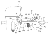
- the sheet 100 is normally supported by a guide member 110 so as to be movable with respect to the guide rail 10.
- the guide member 110 has a main body portion 112 made of iron or the like and a resin portion 114.
- the main body portion 112 is a portion for supporting the load of the seat with respect to the guide rail 10, and the resin portion 114 is, for example, a resin cleaner for removing dust or the like on the guide rail 10.
- the guide member 110 may hit the luggage holding device 20 with a strong impact.
- the extending portion 24Aq (or 24Bq) of the leg piece 24 abuts on the main body portion 112 of the guide member 110, thereby preventing the resin portion 114 from being damaged.
- the pedestal portion 21 formed of zinc is damaged, so that the guide member 110 can be prevented from being damaged.
- the pedestal 21 side is damaged, so that it is possible to suppress damage to other members that hit the pedestal 21 side.
- the lock portion 50 is rotatable around the axis of the shaft body 40 with respect to the pedestal portion 21, but this is not always necessary. After the lock portion is disposed in the guide rail through the slit, the entire load holding device including the pedestal portion is rotated so that the lock portion can come into contact with the inner surfaces of the pair of guide pieces. Good. In this case, the leg piece 24 and the like may be omitted.
- the lock lever 60 is in the unlocked posture in the standing posture and in the locked posture in the sleeping posture, but this is not necessarily required.
- the relationship between the undulating state of the lock lever and the locking and unlocking postures may be reversed.
- the configuration for maintaining the posture change state of the lock lever 60 is not limited to the example of the above embodiment.
- the lock lever may be kept in the locked posture by hooking another member to the lock lever.
Landscapes
- Engineering & Computer Science (AREA)
- Transportation (AREA)
- Mechanical Engineering (AREA)
- Vehicle Step Arrangements And Article Storage (AREA)
- Lock And Its Accessories (AREA)
Abstract
Description
なお、上記実施形態では、ロック部50が台座部21に対してシャフト体40の軸周りに回転自在とされているが、必ずしもその必要はない。ロック部を、スリットを介してガイドレール内に配設後、台座部を含む荷物保持装置全体を回転させることで、ロック部が一対のガイド片の内面側に当接可能となるようにしてもよい。この場合、上記脚片24等を省略するとよい。
Claims (12)
- スリットを介して対向する一対のガイド片を有するガイドレールに取付可能な車両の荷物保持装置であって、
前記一対のガイド片に跨るようにして配設可能な当接部を有する台座部と、
前記台座部に設けられ、荷物を保持するための係止部と、
一端部を前記当接部側から突出させると共に他端部を前記当接部とは反対側から突出させるように、前記台座部に軸方向に沿って移動可能に支持されたシャフト体と、
幅寸法は前記スリットの幅寸法よりも小さく長さ寸法は前記スリットの幅寸法よりも大きい長尺状に形成され、前記シャフト体の一端部に支持されて前記台座部に対して接近離隔移動可能に配設されたロック部と、
前記シャフト体の他端部に姿勢変更可能に支持され、前記ロック部を前記台座部側に引寄せるロック姿勢と、前記ロック部を前記台座部から離間可能な状態にするロック解除姿勢との間で姿勢変更可能なロックレバーと、
を備える車両の荷物保持装置。 - 請求項1記載の車両の荷物保持装置であって、
前記ロック部を、前記台座部から離間させる方向に付勢する離間弾性部材をさらに備える車両の荷物保持装置。 - 請求項1記載の車両の荷物保持装置であって、
前記台座部に、前記スリット内に移動可能に配設される脚片が設けられた、車両の荷物保持装置。 - 請求項3記載の車両の荷物保持装置であって、
前記脚片は、前記ガイドレールのうち前記スリットに対向して形成された位置決め凹部に係合可能な位置決め延設部が形成された、車両の荷物保持装置。 - 請求項1記載の車両の荷物保持装置であって、
前記シャフト体の一端部には前記ロック部が回転不能に支持され、前記シャフト体の他端部は前記台座部に回転可能に支持され、
前記ロックレバーの回転操作により、前記シャフト体を介して前記ロック部が前記シャフト体の軸周りに回転される、車両の荷物保持装置。 - 請求項1記載の車両の荷物保持装置であって、
前記台座部に、前記係止部を姿勢変更可能に支持する一対の軸受部が突設され、
前記ロックレバーは、前記ロック姿勢で前記一対の軸受部間に配設される、車両の荷物保持装置。 - 請求項1記載の車両の荷物保持装置であって、
前記台座部に、前記係止部を姿勢変更可能に支持する一対の軸受部が突設され、
前記一対の軸受部と前記係止部が前記軸受部に支持される両端部とのそれぞれの間に、リング部材が介在する、車両の荷物保持装置。 - 請求項1記載の車両の荷物保持装置であって、
前記台座部に、前記ロックレバーが起立姿勢に姿勢変更する際に、前記ロックレバーを受止めるレバー受止部が設けられた、車両の荷物保持装置。 - 請求項1記載の車両の荷物保持装置であって、
前記台座部に、前記ロックレバーの姿勢を示すロック状態表示部が設けられている、車両の荷物保持装置。 - 請求項1記載の車両の荷物保持装置であって、
前記台座部は、亜鉛で形成されている、車両の荷物保持装置。 - 請求項1記載の車両の荷物保持装置であって、
前記ロックレバーの姿勢変更により、前記シャフト体は、介在弾性部材を介して、前記ロック部を前記台座部側に引寄せる、車両の荷物保持装置。 - 請求項11記載の車両の荷物保持装置であって、
前記介在弾性体は、直列に配設された複数の皿バネを有する、車両の荷物保持装置。
Priority Applications (3)
| Application Number | Priority Date | Filing Date | Title |
|---|---|---|---|
| CN2010800194666A CN102414046A (zh) | 2009-04-30 | 2010-03-12 | 车辆的行李保持装置 |
| EP10769563.7A EP2426009B1 (en) | 2009-04-30 | 2010-03-12 | Cargo retainer device for vehicle |
| US13/201,088 US20110315731A1 (en) | 2009-04-30 | 2010-03-12 | Cargo retainer device for vehicle |
Applications Claiming Priority (2)
| Application Number | Priority Date | Filing Date | Title |
|---|---|---|---|
| JP2009110616A JP5095673B2 (ja) | 2009-04-30 | 2009-04-30 | 車両の荷物保持装置 |
| JP2009-110616 | 2009-04-30 |
Publications (1)
| Publication Number | Publication Date |
|---|---|
| WO2010125863A1 true WO2010125863A1 (ja) | 2010-11-04 |
Family
ID=43032016
Family Applications (1)
| Application Number | Title | Priority Date | Filing Date |
|---|---|---|---|
| PCT/JP2010/054171 Ceased WO2010125863A1 (ja) | 2009-04-30 | 2010-03-12 | 車両の荷物保持装置 |
Country Status (6)
| Country | Link |
|---|---|
| US (1) | US20110315731A1 (ja) |
| EP (1) | EP2426009B1 (ja) |
| JP (1) | JP5095673B2 (ja) |
| KR (1) | KR20120020098A (ja) |
| CN (1) | CN102414046A (ja) |
| WO (1) | WO2010125863A1 (ja) |
Cited By (1)
| Publication number | Priority date | Publication date | Assignee | Title |
|---|---|---|---|---|
| WO2024176712A1 (ja) * | 2023-02-24 | 2024-08-29 | カワサキモータース株式会社 | 飛行体運搬台、飛行体運搬システム、コンテナ及び飛行体運搬方法 |
Families Citing this family (9)
| Publication number | Priority date | Publication date | Assignee | Title |
|---|---|---|---|---|
| JP2013011303A (ja) * | 2011-06-29 | 2013-01-17 | Nifco Inc | 掛止具 |
| FR3019115B1 (fr) * | 2014-03-27 | 2016-04-15 | A Raymond Et Cie | Dispositif d'accrochage a un rail |
| DE102014109311B4 (de) * | 2014-07-03 | 2019-07-04 | Lenz, Kämper GmbH & Co. KG | Verzurröse zur verschiebbaren und arretierbaren Anordnung an einer Laderaumschiene eines Kraftfahrzeugs |
| DE102019204386B4 (de) * | 2019-03-28 | 2021-02-04 | Kipp Gmbh & Co Kg | Befestigungssystem mit einer Lastschiene und einem Lastschlitten, insbesondere für einen Pick-Up-Truck |
| CA3110546A1 (en) * | 2020-02-28 | 2021-08-28 | Michel Bourassa | Locking device for an anchor for connecting an accessory to a vehicle |
| US12296732B2 (en) * | 2021-06-28 | 2025-05-13 | Bombardier Recreational Products Inc. | Seat and accessory connection system for a vehicle |
| CN118139764A (zh) * | 2021-06-30 | 2024-06-04 | 123莱什私人有限公司 | 固定组件、基座和提升辅助件 |
| US12473756B2 (en) * | 2021-10-27 | 2025-11-18 | The Boeing Company | Adjustable latch systems and methods |
| EP4520654A1 (en) | 2023-09-11 | 2025-03-12 | AIRBUS HELICOPTERS DEUTSCHLAND GmbH | An apparatus for connection to an anchor track or an anchor point in an aircraft |
Citations (6)
| Publication number | Priority date | Publication date | Assignee | Title |
|---|---|---|---|---|
| JP2000052848A (ja) * | 1998-08-07 | 2000-02-22 | Piolax Inc | 自動車ハンガーレール用ランナー |
| JP2000103278A (ja) * | 1998-09-30 | 2000-04-11 | Mazda Motor Corp | フック構造 |
| JP2002331865A (ja) * | 2001-05-09 | 2002-11-19 | Piolax Inc | 車両用掛止装置 |
| JP2005067393A (ja) | 2003-08-25 | 2005-03-17 | Kasai Kogyo Co Ltd | 車両の荷物保持装置 |
| JP2007001396A (ja) * | 2005-06-23 | 2007-01-11 | Ihara Kogyo:Kk | 固縛部材連結固定装置 |
| JP2008260525A (ja) * | 2007-04-13 | 2008-10-30 | Bos Gmbh & Co Kg | 移送手段内に積荷を固定する装置 |
Family Cites Families (12)
| Publication number | Priority date | Publication date | Assignee | Title |
|---|---|---|---|---|
| US3605637A (en) * | 1970-09-02 | 1971-09-20 | Ancra Corp | Anchor fitting for securing loads to a retainer track |
| US4047689A (en) * | 1976-07-19 | 1977-09-13 | Uop Inc. | Load distributing track fitting |
| US4850769A (en) * | 1987-06-08 | 1989-07-25 | James E. Irvin | Tie-down device |
| DE10149186B4 (de) * | 2001-10-05 | 2005-02-10 | Bayerische Motoren Werke Ag | Lastöse mit einer schienenförmigen Halterung für den Laderaum eines Kraftfahrzeuges |
| US7040849B2 (en) * | 2003-04-16 | 2006-05-09 | Sportrack Llc | Securement mechanism including top loading tie down cleat assembly and locking member |
| DE10324648B4 (de) * | 2003-05-30 | 2008-01-10 | Airbus Deutschland Gmbh | Vorrichtung zur Aufnahme von Zurrvorrichtungen für ein Frachtladesystem eines Transportmittels, insbesondere eines Flugzeuges |
| DE10324650B4 (de) * | 2003-05-30 | 2005-04-28 | Airbus Gmbh | Zurrvorrichtung für ein Frachtladesystem eines Transportmittels, insbesondere eines Flugzeuges |
| US7637705B2 (en) * | 2004-02-27 | 2009-12-29 | Valeda Company | Track fitting with visual indicia of engagement |
| US7401995B2 (en) * | 2005-03-31 | 2008-07-22 | Nissan Technical Center North America, Inc. | Channel connector |
| DE202006010599U1 (de) * | 2005-07-14 | 2006-10-05 | Ymos Gmbh | Verzurrvorrichtung |
| DE102005061493B4 (de) * | 2005-12-22 | 2010-09-09 | Kipp Gmbh & Co. Kg Cargo & Safety Systems | Gepäckhalteeinrichtung |
| US7874774B2 (en) * | 2007-09-20 | 2011-01-25 | Nissan North America, Inc. | Vehicle cargo arrangement |
-
2009
- 2009-04-30 JP JP2009110616A patent/JP5095673B2/ja not_active Expired - Fee Related
-
2010
- 2010-03-12 KR KR1020117020403A patent/KR20120020098A/ko not_active Withdrawn
- 2010-03-12 CN CN2010800194666A patent/CN102414046A/zh active Pending
- 2010-03-12 EP EP10769563.7A patent/EP2426009B1/en not_active Not-in-force
- 2010-03-12 WO PCT/JP2010/054171 patent/WO2010125863A1/ja not_active Ceased
- 2010-03-12 US US13/201,088 patent/US20110315731A1/en not_active Abandoned
Patent Citations (6)
| Publication number | Priority date | Publication date | Assignee | Title |
|---|---|---|---|---|
| JP2000052848A (ja) * | 1998-08-07 | 2000-02-22 | Piolax Inc | 自動車ハンガーレール用ランナー |
| JP2000103278A (ja) * | 1998-09-30 | 2000-04-11 | Mazda Motor Corp | フック構造 |
| JP2002331865A (ja) * | 2001-05-09 | 2002-11-19 | Piolax Inc | 車両用掛止装置 |
| JP2005067393A (ja) | 2003-08-25 | 2005-03-17 | Kasai Kogyo Co Ltd | 車両の荷物保持装置 |
| JP2007001396A (ja) * | 2005-06-23 | 2007-01-11 | Ihara Kogyo:Kk | 固縛部材連結固定装置 |
| JP2008260525A (ja) * | 2007-04-13 | 2008-10-30 | Bos Gmbh & Co Kg | 移送手段内に積荷を固定する装置 |
Non-Patent Citations (1)
| Title |
|---|
| See also references of EP2426009A4 * |
Cited By (1)
| Publication number | Priority date | Publication date | Assignee | Title |
|---|---|---|---|---|
| WO2024176712A1 (ja) * | 2023-02-24 | 2024-08-29 | カワサキモータース株式会社 | 飛行体運搬台、飛行体運搬システム、コンテナ及び飛行体運搬方法 |
Also Published As
| Publication number | Publication date |
|---|---|
| CN102414046A (zh) | 2012-04-11 |
| EP2426009A4 (en) | 2012-05-23 |
| EP2426009B1 (en) | 2013-05-08 |
| KR20120020098A (ko) | 2012-03-07 |
| US20110315731A1 (en) | 2011-12-29 |
| EP2426009A1 (en) | 2012-03-07 |
| JP5095673B2 (ja) | 2012-12-12 |
| JP2010260385A (ja) | 2010-11-18 |
Similar Documents
| Publication | Publication Date | Title |
|---|---|---|
| JP5095673B2 (ja) | 車両の荷物保持装置 | |
| US20130214112A1 (en) | Seat slide apparatus for vehicle | |
| US8408507B2 (en) | Locking device | |
| CA2784589C (en) | Adaptive carrier insert bar assembly | |
| US20160090012A1 (en) | Over-travel mechanism for easy-entry system | |
| US9573429B2 (en) | Carrier insert bar assembly with securement pin | |
| US8162393B2 (en) | Headrest | |
| CN102910091B (zh) | 车辆座椅 | |
| US20070046087A1 (en) | Child car seat | |
| US11124091B2 (en) | Seat release mechanism | |
| US20150015048A1 (en) | Folding mechanism for a head restraint | |
| JP4447024B2 (ja) | ロック装置 | |
| CN201105664Y (zh) | 车辆用座椅的锁定装置 | |
| US7219943B2 (en) | Remote control unit storage device | |
| JP2013095272A (ja) | 跳ね上げシートロック機構付き車両用シート | |
| KR200404770Y1 (ko) | 차량용 루프 캐리어의 크로스바 고정장치 | |
| US7452020B2 (en) | Self locating bracket | |
| KR100599493B1 (ko) | 루프캐리어의 루프랙과 크로스바의 록킹장치 | |
| JP4356112B2 (ja) | 車両用荷受装置 | |
| JP2016097755A (ja) | ストライカー、車両用シートのロック構造 | |
| JP2010007460A (ja) | ロック装置 | |
| US10207610B2 (en) | Articulating locking mechanism for a seatback | |
| JP2011195098A (ja) | 横跳ね上げシートのロック機構 | |
| JP4921892B2 (ja) | 車両の着座シート | |
| JP6568661B2 (ja) | 車両用トノカバー |
Legal Events
| Date | Code | Title | Description |
|---|---|---|---|
| WWE | Wipo information: entry into national phase |
Ref document number: 201080019466.6 Country of ref document: CN |
|
| 121 | Ep: the epo has been informed by wipo that ep was designated in this application |
Ref document number: 10769563 Country of ref document: EP Kind code of ref document: A1 |
|
| WWE | Wipo information: entry into national phase |
Ref document number: 5529/CHENP/2011 Country of ref document: IN |
|
| WWE | Wipo information: entry into national phase |
Ref document number: 13201088 Country of ref document: US |
|
| WWE | Wipo information: entry into national phase |
Ref document number: 2010769563 Country of ref document: EP |
|
| ENP | Entry into the national phase |
Ref document number: 20117020403 Country of ref document: KR Kind code of ref document: A |
|
| NENP | Non-entry into the national phase |
Ref country code: DE |