WO2010126119A1 - 燃料電池用アノード側触媒組成物および固体高分子形燃料電池用膜電極接合体(mea) - Google Patents
燃料電池用アノード側触媒組成物および固体高分子形燃料電池用膜電極接合体(mea) Download PDFInfo
- Publication number
- WO2010126119A1 WO2010126119A1 PCT/JP2010/057638 JP2010057638W WO2010126119A1 WO 2010126119 A1 WO2010126119 A1 WO 2010126119A1 JP 2010057638 W JP2010057638 W JP 2010057638W WO 2010126119 A1 WO2010126119 A1 WO 2010126119A1
- Authority
- WO
- WIPO (PCT)
- Prior art keywords
- catalyst
- metal
- anode
- fuel cell
- cathode
- Prior art date
- Legal status (The legal status is an assumption and is not a legal conclusion. Google has not performed a legal analysis and makes no representation as to the accuracy of the status listed.)
- Ceased
Links
Images


Classifications
-
- H—ELECTRICITY
- H01—ELECTRIC ELEMENTS
- H01M—PROCESSES OR MEANS, e.g. BATTERIES, FOR THE DIRECT CONVERSION OF CHEMICAL ENERGY INTO ELECTRICAL ENERGY
- H01M4/00—Electrodes
- H01M4/86—Inert electrodes with catalytic activity, e.g. for fuel cells
- H01M4/90—Selection of catalytic material
- H01M4/9016—Oxides, hydroxides or oxygenated metallic salts
- H01M4/9025—Oxides specially used in fuel cell operating at high temperature, e.g. SOFC
- H01M4/9033—Complex oxides, optionally doped, of the type M1MeO3, M1 being an alkaline earth metal or a rare earth, Me being a metal, e.g. perovskites
-
- H—ELECTRICITY
- H01—ELECTRIC ELEMENTS
- H01M—PROCESSES OR MEANS, e.g. BATTERIES, FOR THE DIRECT CONVERSION OF CHEMICAL ENERGY INTO ELECTRICAL ENERGY
- H01M4/00—Electrodes
- H01M4/86—Inert electrodes with catalytic activity, e.g. for fuel cells
- H01M4/90—Selection of catalytic material
-
- H—ELECTRICITY
- H01—ELECTRIC ELEMENTS
- H01M—PROCESSES OR MEANS, e.g. BATTERIES, FOR THE DIRECT CONVERSION OF CHEMICAL ENERGY INTO ELECTRICAL ENERGY
- H01M4/00—Electrodes
- H01M4/86—Inert electrodes with catalytic activity, e.g. for fuel cells
- H01M4/8647—Inert electrodes with catalytic activity, e.g. for fuel cells consisting of more than one material, e.g. consisting of composites
- H01M4/8652—Inert electrodes with catalytic activity, e.g. for fuel cells consisting of more than one material, e.g. consisting of composites as mixture
-
- H—ELECTRICITY
- H01—ELECTRIC ELEMENTS
- H01M—PROCESSES OR MEANS, e.g. BATTERIES, FOR THE DIRECT CONVERSION OF CHEMICAL ENERGY INTO ELECTRICAL ENERGY
- H01M4/00—Electrodes
- H01M4/86—Inert electrodes with catalytic activity, e.g. for fuel cells
- H01M4/88—Processes of manufacture
- H01M4/8878—Treatment steps after deposition of the catalytic active composition or after shaping of the electrode being free-standing body
- H01M4/8882—Heat treatment, e.g. drying, baking
- H01M4/8885—Sintering or firing
-
- H—ELECTRICITY
- H01—ELECTRIC ELEMENTS
- H01M—PROCESSES OR MEANS, e.g. BATTERIES, FOR THE DIRECT CONVERSION OF CHEMICAL ENERGY INTO ELECTRICAL ENERGY
- H01M4/00—Electrodes
- H01M4/86—Inert electrodes with catalytic activity, e.g. for fuel cells
- H01M4/90—Selection of catalytic material
- H01M4/92—Metals of platinum group
- H01M4/925—Metals of platinum group supported on carriers, e.g. powder carriers
- H01M4/926—Metals of platinum group supported on carriers, e.g. powder carriers on carbon or graphite
-
- H—ELECTRICITY
- H01—ELECTRIC ELEMENTS
- H01M—PROCESSES OR MEANS, e.g. BATTERIES, FOR THE DIRECT CONVERSION OF CHEMICAL ENERGY INTO ELECTRICAL ENERGY
- H01M4/00—Electrodes
- H01M4/86—Inert electrodes with catalytic activity, e.g. for fuel cells
- H01M4/96—Carbon-based electrodes
-
- H—ELECTRICITY
- H01—ELECTRIC ELEMENTS
- H01M—PROCESSES OR MEANS, e.g. BATTERIES, FOR THE DIRECT CONVERSION OF CHEMICAL ENERGY INTO ELECTRICAL ENERGY
- H01M8/00—Fuel cells; Manufacture thereof
- H01M8/10—Fuel cells with solid electrolytes
-
- H—ELECTRICITY
- H01—ELECTRIC ELEMENTS
- H01M—PROCESSES OR MEANS, e.g. BATTERIES, FOR THE DIRECT CONVERSION OF CHEMICAL ENERGY INTO ELECTRICAL ENERGY
- H01M8/00—Fuel cells; Manufacture thereof
- H01M8/10—Fuel cells with solid electrolytes
- H01M8/1004—Fuel cells with solid electrolytes characterised by membrane-electrode assemblies [MEA]
-
- H—ELECTRICITY
- H01—ELECTRIC ELEMENTS
- H01M—PROCESSES OR MEANS, e.g. BATTERIES, FOR THE DIRECT CONVERSION OF CHEMICAL ENERGY INTO ELECTRICAL ENERGY
- H01M4/00—Electrodes
- H01M4/86—Inert electrodes with catalytic activity, e.g. for fuel cells
- H01M2004/8678—Inert electrodes with catalytic activity, e.g. for fuel cells characterised by the polarity
- H01M2004/8689—Positive electrodes
-
- H—ELECTRICITY
- H01—ELECTRIC ELEMENTS
- H01M—PROCESSES OR MEANS, e.g. BATTERIES, FOR THE DIRECT CONVERSION OF CHEMICAL ENERGY INTO ELECTRICAL ENERGY
- H01M8/00—Fuel cells; Manufacture thereof
- H01M8/10—Fuel cells with solid electrolytes
- H01M2008/1095—Fuel cells with polymeric electrolytes
-
- H—ELECTRICITY
- H01—ELECTRIC ELEMENTS
- H01M—PROCESSES OR MEANS, e.g. BATTERIES, FOR THE DIRECT CONVERSION OF CHEMICAL ENERGY INTO ELECTRICAL ENERGY
- H01M8/00—Fuel cells; Manufacture thereof
- H01M8/10—Fuel cells with solid electrolytes
- H01M8/12—Fuel cells with solid electrolytes operating at high temperature, e.g. with stabilised ZrO2 electrolyte
- H01M2008/1293—Fuel cells with solid oxide electrolytes
-
- H—ELECTRICITY
- H01—ELECTRIC ELEMENTS
- H01M—PROCESSES OR MEANS, e.g. BATTERIES, FOR THE DIRECT CONVERSION OF CHEMICAL ENERGY INTO ELECTRICAL ENERGY
- H01M2250/00—Fuel cells for particular applications; Specific features of fuel cell system
- H01M2250/20—Fuel cells in motive systems, e.g. vehicle, ship, plane
-
- H—ELECTRICITY
- H01—ELECTRIC ELEMENTS
- H01M—PROCESSES OR MEANS, e.g. BATTERIES, FOR THE DIRECT CONVERSION OF CHEMICAL ENERGY INTO ELECTRICAL ENERGY
- H01M2250/00—Fuel cells for particular applications; Specific features of fuel cell system
- H01M2250/30—Fuel cells in portable systems, e.g. mobile phone, laptop
-
- H—ELECTRICITY
- H01—ELECTRIC ELEMENTS
- H01M—PROCESSES OR MEANS, e.g. BATTERIES, FOR THE DIRECT CONVERSION OF CHEMICAL ENERGY INTO ELECTRICAL ENERGY
- H01M4/00—Electrodes
- H01M4/86—Inert electrodes with catalytic activity, e.g. for fuel cells
- H01M4/90—Selection of catalytic material
- H01M4/9016—Oxides, hydroxides or oxygenated metallic salts
-
- Y—GENERAL TAGGING OF NEW TECHNOLOGICAL DEVELOPMENTS; GENERAL TAGGING OF CROSS-SECTIONAL TECHNOLOGIES SPANNING OVER SEVERAL SECTIONS OF THE IPC; TECHNICAL SUBJECTS COVERED BY FORMER USPC CROSS-REFERENCE ART COLLECTIONS [XRACs] AND DIGESTS
- Y02—TECHNOLOGIES OR APPLICATIONS FOR MITIGATION OR ADAPTATION AGAINST CLIMATE CHANGE
- Y02E—REDUCTION OF GREENHOUSE GAS [GHG] EMISSIONS, RELATED TO ENERGY GENERATION, TRANSMISSION OR DISTRIBUTION
- Y02E60/00—Enabling technologies; Technologies with a potential or indirect contribution to GHG emissions mitigation
- Y02E60/30—Hydrogen technology
- Y02E60/50—Fuel cells
Definitions
- the present invention relates to a fuel cell anode catalyst composition and a membrane electrode assembly (MEA) for a polymer electrolyte fuel cell using the same.
- MEA membrane electrode assembly
- Fuel cells have attracted attention as highly efficient energy conversion devices. Fuel cells are roughly classified into low-temperature operating fuel cells such as alkaline, solid polymer and phosphoric acid types, and high-temperature operating fuel cells such as molten carbonate and solid oxide types, depending on the type of electrolyte used. .
- a polymer electrolyte fuel cell (PEFC) using a polymer electrolyte membrane having ion conductivity as an electrolyte can obtain a high output density with a compact structure, and does not use a liquid as an electrolyte. Since it can be realized with a simple system because it can be operated, it has been attracting attention as a power source for stationary use, vehicle use, portable use and the like.
- PEFC polymer electrolyte fuel cell
- a polymer electrolyte fuel cell has gas diffusible electrode layers on both sides of a polymer electrolyte membrane.
- the anode side is exposed to a fuel gas (hydrogen, etc.) and the cathode side is exposed to an oxidant gas (air, etc.).
- the basic principle is to synthesize water by a chemical reaction through a polymer electrolyte membrane and to electrically extract the reaction energy generated thereby.
- the fuel cell system is being put into practical use due to efficient power generation characteristics, and has been able to exhibit practical durability in steady operation.
- the system becomes expensive due to the use of platinum as an electrode catalyst, and that irreversible degradation is promoted in unsteady operation such as fuel shortage and start / stop. For these reasons, it is necessary to improve these issues.
- the steady state of the fuel cell is a hydrogen atmosphere on the anode side and an air atmosphere on the cathode side.
- starting and stopping are performed by supplying air to the anode side to stop power generation.
- both the anode and the cathode are in an air atmosphere, and hydrogen is supplied to the anode in the air atmosphere to start power generation (startup).
- startup start power generation
- Patent Document 2 discloses a technique of mixing a water electrolysis catalyst such as iridium oxide with an electrode catalyst in order to prevent the anode catalyst carrier from being corroded at the time of hydrogen deficiency. According to this technique, the resistance of the fuel cell to battery inversion can be made stronger.
- Patent Document 3 in the fuel electrode of a solid polymer electrolyte fuel cell, at least one reaction layer that contacts the solid polymer electrolyte membrane and causes the fuel cell reaction to proceed, and a diffusion layer contact the fuel electrode (anode).
- Patent Documents 4 and 5 are examples of using highly crystallized carbon for platinum used for the cathode catalyst and examples of using platinum black.
- a fuel cell anode-side catalyst composition comprising a catalyst having catalyst particles supported on a conductive material and an ion exchange resin, wherein the catalyst particles have both oxygen reduction ability and water electrolysis overvoltage lower than platinum, and A catalyst composition comprising a metal, a metal oxide, a partial oxide of metal, or a mixture thereof having hydrogen oxidizing ability is provided.
- (2) The catalyst composition according to (1), wherein the metal is selected from the group consisting of iridium, ruthenium, rhenium, palladium, and rhodium.
- (3) The catalyst composition according to (1) or (2), wherein the catalyst particles contain the metal and the average crystallite size of the metal is in the range of 2 nm to 20 nm.
- the charge amount (Q H ) of the hydrogen adsorption region per unit mass of the metal is in the range of 15.0 to 65.0 C / mg (metal), according to any one of (1) to (3)
- the described catalyst composition is provided.
- the described catalyst composition is provided.
- the peak in Ir4f7 / 2 of the X-ray photoelectron spectrometer (XPS) spectrum of the catalyst particle is included in any of 60.8 to 61.4 (eV), (1) to (5)
- the catalyst composition is provided.
- (7) The catalyst composition according to any one of (1) to (6), wherein the conductive material is a highly graphitized carbon black having a BET specific surface area of 50 m 2 / g or more and 300 m 2 / g or less. Provided.
- a membrane electrode assembly (MEA) for a polymer electrolyte fuel cell in which an anode catalyst layer is bonded to one surface of a polymer electrolyte membrane and a cathode catalyst layer is bonded to the opposite surface thereof.
- An MEA is provided in which the catalyst layer comprises the catalyst composition according to any one of (1) to (7).
- the deterioration of the fuel cell due to unsteady operation is suppressed, and platinum (Pt), which occupies most of the cost of the fuel cell, is not used at the anode at all.
- Pt platinum
- a high-performance fuel cell can be obtained.
- the present invention even when the amount of hydrogen supplied during the operation of the fuel cell is insufficient, the elution problem of the catalyst is solved. Therefore, it is possible to prevent deterioration of the anode without using a platinum catalyst. Further, according to the present invention, it is possible to reduce the deterioration of the anode and the cathode when the fuel cell is started and stopped.
- the present invention can fundamentally solve the main causes of fuel cell deterioration such as fuel deficiency (polarization) and start / stop. Therefore, the portion protected by the conventional system can be reduced, thereby reducing the cost of the entire system.
- FIG. 3 is a diagram showing X-ray diffraction (XRD) patterns of carbon-supported iridium catalysts A1 to A4 produced by heat treatment in a reducing atmosphere.
- FIG. 3 is a diagram showing XRD patterns of carbon-supported iridium oxide catalysts B1 to B3 and catalyst A1 prepared by heat-treating catalyst A1 in an oxidizing atmosphere. It is a figure of current density vs. reversible hydrogen electrode potential obtained by performing cyclic voltammetry using an anode as a working electrode.
- the catalyst composition according to the present invention is a fuel cell anode-side catalyst composition comprising a catalyst having catalyst particles supported on a conductive material and an ion exchange resin, wherein the catalyst particles have both oxygen reduction ability and water electrolysis overvoltage. It is characterized by comprising a metal, a metal oxide, a partial oxide of metal, or a mixture thereof, which is lower than platinum and has a hydrogen oxidizing ability.
- the fuel cell has a basic structure in which a polymer electrolyte membrane and a catalyst layer bonded to both sides thereof are arranged.
- One of the catalyst layers is an anode that reacts with a fuel (such as hydrogen).
- the other of the catalyst layers is a cathode that reacts with an oxidant gas (such as oxygen).
- the catalyst particles contained in the catalyst composition of the present invention have a hydrogen oxidizing ability, that is, an ability to advance the reaction [1]. Thereby, the catalyst composition containing the catalyst particles works as an anode side catalyst composition for a fuel cell.
- the catalyst particles have a water electrolysis overvoltage lower than that of platinum.
- the water electrolysis overvoltage means a potential difference necessary for proceeding with the next reaction [3]. That is, when this catalyst particle is used, the reaction [3] proceeds with a lower potential difference than when platinum is used as a catalyst.
- H 2 O ⁇ 1 / 2O 2 + 2H + + 2e - ⁇ [3] As a result, anode deterioration can be suppressed.
- a catalyst having an oxygen generation overvoltage lower than that of platinum at the time of water electrolysis is used, so that an increase in anode potential at the time of fuel depletion can be suppressed. That is, by smoothly performing the water electrolysis reaction [3] at the anode that occurs at the time of fuel depletion, the reaction [4] that produces H + due to corrosion of the anode (catalyst support carbon) is less likely to occur, and as a result Degradation of the anode can be suppressed.
- the catalyst particles have a lower oxygen reducing ability than platinum.
- the oxygen reducing ability is the ability to proceed with the next reaction [2]. O 2 + 4H + + 4e ⁇ ⁇ 2H 2 O [2]
- the oxygen reducing ability is lower than that of platinum, it becomes possible to reduce the deterioration of the fuel cell at the time of starting and stopping.
- the mechanism of deterioration of the fuel cell at the start and stop is that the oxygen reduction reaction [2] occurs at the anode and the corresponding oxidation reaction occurs at the cathode of the counter electrode, but fuel (hydrogen etc.) as an oxide is supplied to the cathode.
- a corrosion reaction [4] occurs in which carbon existing as an electrode material is oxidized. 1 / 2C + H 2 O ⁇ 1 / 2CO 2 + 2H + + 2e - ⁇ [4]
- the catalyst having a low oxygen reduction activity is used for the anode to suppress the oxygen reduction reaction [2] at the anode, thereby suppressing the cathodic corrosion reaction [4] at the time of starting and stopping. It becomes possible to reduce deterioration.
- the catalyst particles of the present invention are made of a metal satisfying the above properties, a metal oxide thereof, a partial oxide of the metal, or a mixture thereof.
- the metal partial oxide means that the central part of the catalyst particle is a metal and the surface part of the catalyst particle is a metal oxide, the central part of the catalyst particle is a metal oxide and the surface part of the catalyst particle is a metal. It means something.
- the metal element to be the anode side catalyst composition of the present invention can be selected from the group consisting of iridium, ruthenium, rhenium, palladium and rhodium. These metal elements have both oxygen reduction ability and water electrolysis overvoltage lower than platinum, and have hydrogen oxidation ability. In particular, iridium is preferable because it has the lowest water electrolysis overvoltage and high hydrogen oxidation ability. Since the anode side catalyst composition of the present invention does not require platinum, a low-cost fuel cell can be obtained.
- the average crystallite size of the metal is preferably 2 nm to 20 nm.
- the metal contained in the catalyst particles is considerably eluted, causing various problems.
- the metal contained in the catalyst particles may be eluted when the potential of the anode fluctuates due to the start / stop operation of the fuel cell, and the eluted metal causes a problem of lowering the proton conductivity of the electrolyte membrane. Further, when the eluted metal moves to the cathode, the oxygen reduction reaction of the cathode is hindered and the generated voltage is lowered. Such a metal elution problem is considered to be affected by the particle size and electronic state of the metal.
- the present inventor has found that the outflow of the metal contained in the catalyst particles can be significantly reduced by setting the average crystallite size to 2 nm or more.
- the average crystallite size of the metal contained in the catalyst particles is larger than 20 nm, the effective specific surface area of the metal is lowered, the water electrolysis ability is lowered (the reaction efficiency of [3] is lowered), and as a result The inversion durability in a hydrogen deficient operation is reduced. In order to compensate for this decrease in durability, it is necessary to increase the amount of catalyst supported, and a low-cost fuel cell cannot be obtained.
- the metal is coarsened by heat-treating the metal at 200 ° C. to 800 ° C. in a reducing atmosphere. Thereby, the average crystallite size of the metal can be adjusted.
- the charge amount (Q H ) of the hydrogen adsorption region per unit mass of the metal is preferably in the range of 15.0 to 65.0 C / mg (metal).
- the charge amount (Q H ) of the hydrogen adsorption region per unit mass of the catalyst is proportional to the catalyst surface area. That is, the charge amount (Q H ) has a correlation with the average crystallite size of the catalyst metal. That is, it is considered that the smaller the average crystallite size is, the larger the surface area of the catalyst is and the amount of charge per metal mass is increased.
- the charge amount (Q H ) of the hydrogen adsorption region per unit mass of the metal is 15.0 to 65 Corresponds to the range of 0.0 C / mg (metal).
- the mass ratio of the metal: the metal oxide or the partial oxide of the metal is within a range of 1:10 to 10: 1. It is preferable that When the metal mass is larger than this range (when the mass of the oxide or partial oxide is less than this range), metal oxidation and coarsening of the metal are insufficient, and elution of the metal component is not reduced. When the metal mass is less than this range (when the mass of the oxide or partial oxide is greater than this range), the oxidation proceeds excessively and the hydrogen oxidation activity of the catalyst is reduced.
- X-ray photoelectron spectroscopy is a method that measures the kinetic energy distribution, angular distribution, spin, etc. of photoelectrons emitted when X-ray monochromatic light such as AlK ⁇ and MgK ⁇ rays is irradiated on the material. This is an experimental method to obtain information about electronic structure, atomic arrangement, magnetic properties, etc. By this method, inner-shell electrons can be emitted, and the ionization energy varies depending on the chemical environment (chemical shift), so that elemental analysis and state analysis can be performed.
- a peak at Ir4f7 / 2 in the XPS spectrum is included between 60.8 and 61.4 (eV).
- This peak at Ir4f7 / 2 has a correlation with the oxidation number of Ir.
- the mass ratio of the metal to the metal oxide or the partial oxide of the metal is within a range of 1:10 to 10: 1.
- the peak at Ir4f7 / 2 is 60.8 to 61.4 (eV). It is equivalent to being included between.
- the metal oxide having such a mass ratio or the partial oxide of the metal can be obtained by heat-treating the metal at 100 ° C. to 300 ° C. in an oxidizing atmosphere.
- oxidation of the metal proceeds simultaneously with the coarsening of the metal, thereby reducing the elution amount of the metal component.
- the mass ratio of the metal: the metal oxide or the partial oxide of the metal is preferably within the above range.
- the carrier for supporting the catalyst particles is preferably carbon with a high degree of graphitization from the viewpoint of corrosion resistance at the time of fuel deficiency, but is not limited to carbon, and applications such as highly durable oxide carriers such as titanium oxide and tin oxide are also applicable. Is possible. When an oxide carrier having insufficient conductivity is applied, it is desirable to ensure conductivity by using a conductive material in combination.
- impurities in the catalyst include anions such as chloride ions.
- the ion exchange resin in the catalyst composition is also a material that supports the catalyst and serves as a binder for forming the catalyst layer, and has a role of forming a passage for ions and the like generated by the catalyst to move.
- Such an ion exchange resin (polymer electrolyte membrane) is not particularly limited as long as it has high proton (H + ) conductivity, is electronically insulating, and is gas impermeable. Any known polymer electrolyte membrane may be used.
- a typical example is a resin having a fluorine-containing polymer as a skeleton and a group such as a sulfonic acid group, a carboxyl group, a phosphoric acid group, or a phosphonic group.
- the thickness of the polymer electrolyte membrane has a great influence on the resistance, a thinner one is required as long as it does not impair the electronic insulation and gas impermeability, specifically 0.1 to 100 ⁇ m, preferably It is set within the range of 0.1 to 30 ⁇ m.
- the material of the polymer electrolyte membrane in the present invention is not limited to a perfluorinated polymer compound, but a mixture of a hydrocarbon polymer compound or an inorganic polymer compound, or a C—H bond and C in a polymer chain. It may be a partially fluorinated polymer compound containing both -F bonds.
- perfluorinated polymer electrolyte membrane examples include Nafion (registered trademark) membrane (manufactured by DuPont) and Aciplex (registered trademark) membrane (manufactured by Asahi Kasei), which are perfluoropolymers having a sulfonic acid group in the side chain. And Flemion (registered trademark) membrane (manufactured by Asahi Glass Co., Ltd.).
- hydrocarbon polymer electrolytes include polyamides, polyacetals, polyethylenes, polypropylenes, acrylic resins, polyesters, polysulfones, polyethers, etc., and derivatives thereof (aliphatic carbonization) into which electrolyte groups such as sulfonic acid groups have been introduced.
- Hydrogen-based polymer electrolytes polystyrene having electrolyte groups such as sulfonic acid groups introduced therein, polyamides having aromatic rings, polyamideimides, polyimides, polyesters, polysulfones, polyetherimides, polyethersulfones, polycarbonates, and derivatives thereof (Partial aromatic hydrocarbon polymer electrolyte), polyetheretherketone, polyetherketone, polyethersulfone, polycarbonate, polyamide, polyamideimide, polyester into which electrolyte groups such as sulfonic acid groups are introduced Polyphenylene sulfide and the like, and derivatives thereof (fully aromatic hydrocarbon-based polymer electrolyte), and the like.
- a siloxane-based or silane-based, particularly alkylsiloxane-based organosilicon polymer compound is suitable, and specific examples include polydimethylsiloxane, ⁇ -glycidoxypropyltrimethoxysilane, and the like.
- Specific examples of the partially fluorinated polymer electrolyte include polystyrene-graft-ethylenetetrafluoroethylene copolymer, polystyrene-graft-polytetrafluoroethylene, etc., into which an electrolyte group such as a sulfonic acid group has been introduced, and these. Derivatives.
- the conductive material carbon-based particles such as carbon black, activated carbon, graphite and the like are suitable, and fine powder particles are particularly preferably used.
- the highly graphitized carbon black particles have a BET surface area of 50 m 2 / g or more.
- the BET surface area of the carbon black particles is preferably 300 m 2 / g or less.
- the catalyst particles noble metal
- the catalyst particles can be supported in fine particles, and the catalyst particles have a small particle size.
- ORR oxygen reduction reaction
- the carbon black particles have a small surface area and a high degree of graphite crystallinity, so that the durability at the time of inversion (at the time of fuel depletion) is improved.
- the BET surface area of the carbon black particles is less than 50 m 2 / g, the surface area is too small and it becomes difficult to uniformly support the catalyst particles.
- the catalyst layer is preferably porous so that a fuel such as hydrogen can be brought into contact with the catalyst as much as possible on the anode side and an oxidant gas such as oxygen and air can be brought on the cathode side.
- the amount of catalyst contained in the catalyst layer may generally be in the range of 0.01 to 5 mg / cm 2 .
- the anode loading is preferably in the range of 0.01 to 0.2 mg / cm 2 .
- the anode carrying amount is preferably 0.2 mg / cm 2 or less because a small carrying amount is preferable from the viewpoints of cost and durability at the time of starting and stopping.
- the amount of the anode supported is too small, the power generation performance is lowered, so that it is preferably 0.01 mg / cm 2 or more.
- the cathode loading is preferably in the range of 0.1 to 0.6 mg / cm 2 .
- the greater the amount of cathode supported the better both the initial activity / durability.
- it is preferably 0.6 mg / cm 2 or less.
- the amount of the cathode supported is too small, the initial activity / durability is significantly lowered, and therefore it is preferably 0.1 mg / cm 2 or more.
- the thickness of the catalyst layer is generally required to be in the range of 1 to 200 ⁇ m, but in particular, it is preferable to be in the range of 1 to 100 ⁇ m for the anode and in the range of 3 to 30 ⁇ m for the cathode.
- the catalyst layer of the cathode of the fuel cell is not particularly limited as long as it contains catalyst particles and an ion exchange resin, and conventionally known ones can be used.
- the catalyst is usually made of a conductive material carrying catalyst particles.
- the catalyst particles may be any catalyst particles that have a catalytic action in the oxidation reaction of hydrogen or the reduction reaction of oxygen.
- platinum (Pt) and other noble metals iron, chromium, nickel, cobalt, etc., and alloys thereof are used. be able to.
- a polymer electrolyte membrane in which an anode catalyst layer is joined to one surface and a cathode catalyst layer is joined to the other surface is called a membrane electrode assembly (MEA).
- MEA membrane electrode assembly
- the present invention also relates to a membrane electrode assembly (MEA) for a polymer electrolyte fuel cell, wherein the anode catalyst layer comprises the above-described catalyst composition.
- This MEA has characteristics based on the above-described catalyst composition contained in the anode catalyst layer, that is, prevents deterioration of the anode that occurs when hydrogen is insufficient, and deterioration of the anode and cathode when the fuel cell starts and stops. The advantages of reducing the cost and cost.
- the MEA can be further provided with a gas diffusion layer on the opposite side of the anode side catalyst layer and / or the cathode side catalyst layer from the polymer electrolyte membrane.
- the gas diffusion layer is a sheet material having conductivity and air permeability. Representative examples include those obtained by subjecting a breathable conductive base material such as carbon paper, carbon woven fabric, carbon nonwoven fabric, carbon felt or the like to a water repellent treatment.
- a porous sheet obtained from carbon-based particles and fluorine-based resin can also be used.
- a porous sheet obtained by forming carbon black into a sheet using polytetrafluoroethylene as a binder can be used.
- the amount of Pt supported at the cathode may be 0.2 mg / cm 2 or less.
- the cathode is conventionally required to have a Pt loading of 0.4 mg / cm 2 or more.
- the deterioration of the cathode is reduced. Therefore, even when the amount of Pt supported on the cathode is 0.2 mg / cm 2 or less, it can be used practically as an MEA. is there.
- Catalyst preparation For battery evaluation, a catalyst in which iridium or its oxide was supported on carbon black was prepared. A series heat-treated in a reducing atmosphere and B series heat-treated in an oxidizing atmosphere were prepared. An R series based on commercial products was also prepared. The detailed preparation procedure of the catalyst used for battery evaluation is shown below.
- iridium chloride (VI) acid hydrate solution was added to the place where the carbon black dispersion was being stirred to prepare a slurry.
- carbon black was impregnated with iridium chloride (VI) acid hydrate with stirring at 80 ° C., and dried to solidify with stirring at the same temperature for about 10 hours.
- iridium chloride (VI) acid hydrate was impregnated with iridium chloride (VI) acid hydrate with stirring at 80 ° C., and dried to solidify with stirring at the same temperature for about 10 hours.
- the obtained powder was pulverized in an agate mortar, and this was heat-treated at 200 ° C. for 2 hours under a mixed gas flow consisting of 10% hydrogen gas and 90% nitrogen gas, to produce a carbon-supported iridium catalyst. did.
- XRD analysis of catalyst Using XRD analysis, the crystal structure and particle size of the produced catalyst were investigated.
- the XRD measurement was performed under the following conditions of continuous scanning (with a wider measurement angle) and step scan (with a smaller measurement angle).
- X-ray target Cu, voltage 40 kV, current 80 mA
- Continuous scan condition Scan speed 2 ° / min; Sampling width 0.02 °
- Step scan condition Measurement time 5 s; Step width 0.02 °.
- FIG. 1 is a diagram showing the results of measuring X-ray diffraction (XRD) patterns of the catalyst A1 (a), the catalyst A2 (b), the catalyst A3 (c), and the catalyst A4 (d). It was found that the higher the heat treatment temperature, the smaller the half width of the diffraction peak, and the crystallite size increased. Table 1 shows the crystallite size obtained from the half width of these peaks.
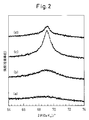
- FIG. 2 is a diagram showing the results of measuring XRD patterns of the catalyst A1 (a), the catalyst B1 (b), the catalyst B2, (c), and the catalyst B3 (d).
- the catalyst A1 has a broad peak from about 32 ° to about 50 °, indicating that a fine metal iridium phase is present.
- the catalyst B1 showed a broader peak than A1, the new peak which shows presence of iridium oxide was not observed.
- the iridium oxide phase does not grow to a size detectable by XRD, that is, only the extreme surface of the metal iridium fine particles is oxidized.
- peaks indicating the presence of the iridium oxide phase were observed at 28.1 ° and 34.7 °, indicating that the iridium oxide phase was generated by the oxidation treatment at 200 ° C. or higher.
- sharp peaks indicating the presence of huge metal iridium particles of about 20 nm at 40.6 ° and 47.2 ° were observed.
- the average crystallite size of B1 is considered to be 2.0 nm or more.
- MEA membrane electrode assembly
- Each carbon-supported catalyst was mixed with alcohol so that the solid content concentration was 9 wt%.
- each mixed solution is added to an ion exchange resin solution (perfluorosulfonic acid electrolyte solution (SE20142); manufactured by DuPont) so that the ion exchange resin solution has a mass ratio of 1.0 with respect to the carrier carbon. It was.
- SE20142 perfluorosulfonic acid electrolyte solution
- the liquid thus prepared was irradiated with ultrasonic waves to disperse the catalyst-supporting carbon to prepare a coating solution.
- the obtained coating solution was applied to a PTFE sheet having a thickness of 200 ⁇ m and dried so that the amount of the noble metal supported was a predetermined amount shown in Table 2, thereby forming an anode electrode layer.
- Table 2 shows the names of anodes, anode catalyst types, and catalyst metal loadings in the comparative examples and examples.
- GORE-SELECT registered trademark 20K (manufactured by Japan Gore-Tex Co., Ltd.) was adopted as the electrolyte membrane.
- a membrane electrode assembly (MEA) was produced from the above anode, cathode and electrolyte membrane by hot pressing and a decal method.
- Each membrane electrode assembly is placed between two sheets of water-repellent carbon paper (CARBEL (registered trademark) CNW10A: manufactured by Japan Gore-Tex Co., Ltd.) and incorporated in a power generation cell. Hydrogen is used on the anode side at normal pressure. 80%), air is supplied to the cathode side (utilization rate 40%), and initial current density is 0.2 A / cm 2 , 0.5 A / cm 2 , 1.0 A / cm 2 at a cell temperature of 80 ° C. A power generation test was conducted. The gas dew point was a high humidification condition, and a gas having a dew point of 80 ° C. was supplied to both the anode and the cathode.
- CARBEL registered trademark
- CNW10A manufactured by Japan Gore-Tex Co., Ltd.
- the catalyst composition of the present invention has an average crystallite size of 2.0 nm to 20 nm.
- the following electrochemical evaluation was performed for the purpose of confirming the presence of fine particles smaller than 2.0 nm of the anode catalyst. Nitrogen gas having a dew point of 80 ° C. was supplied to the anode, and hydrogen gas having a dew point of 80 ° C. was supplied to the cathode.
- cyclic voltammetry is performed using a potentiostat with the anode as the working electrode under the conditions of an upper limit potential of 1.2 V, a lower limit potential of 0.05 V, and a scanning speed of 100 mV / s.
- the amount of charge in the hydrogen adsorption region is obtained from Q H (hydrogen adsorption electricity amount) in the shaded area in FIG. 3, and the maximum value of the x-axis is the value when the slope becomes 0 around 0.35 V, and the double layer capacity portion is Excluded.
- the obtained charge amount was divided by the anode metal mass to obtain the value of the charge amount per metal mass. The values obtained are shown in Table 5.
- the amount of charge per metal mass is considered to have a correlation with the average crystallite size of the catalyst particles. That is, it is considered that the smaller the average crystallite size is, the larger the surface area of the catalyst is and the amount of charge per metal mass is increased.
- the charge amount (Q H ) of the hydrogen adsorption region per unit mass of the metal is 15.0 to 65 Corresponds to the range of 0.0 C / mg (metal).
- Each membrane electrode assembly is placed between two sheets of water-repellent carbon paper (CARBEL (registered trademark) CNW10A: manufactured by Japan Gore-Tex Co., Ltd.) and incorporated in a power generation cell, and hydrogen is used on the cathode side at normal pressure. 80%), oxygen (utilization rate 40%) was supplied to the anode side, and an initial power generation test was carried out at a cell temperature of 80 ° C. and a current density of 0.1 A / cm 2 . As for the gas dew point, a gas having a dew point of 80 ° C. was supplied to both the anode and the cathode. The voltage value after resistance correction obtained there is shown in Table 6.
- CARBEL registered trademark
- CNW10A manufactured by Japan Gore-Tex Co., Ltd.
- the iridium catalysts (Examples 1 to 7) of the present invention have oxygen reducing ability as with the platinum catalysts (Comparative Examples 1 and 2), but the obtained voltage value is that of the platinum catalyst. It turns out that it is low. That is, the iridium-based catalyst has an oxygen reducing ability lower than that of platinum, thereby suppressing deterioration at the time of starting and stopping.
- Each membrane electrode assembly is placed between two sheets of water-repellent carbon paper (CARBEL (registered trademark) CNW20B: manufactured by Japan Gore-Tex Co., Ltd.) and incorporated into a power generation cell. Hydrogen is used on the anode side at normal pressure. Rate 83%), air (utilization rate 50%) was supplied to the cathode side, and a start-stop power generation test was conducted at a cell temperature of 80 ° C. As for the gas dew point, a gas having a dew point of 70 ° C. was supplied to both the anode and the cathode. The start / stop evaluation procedure will be described.
- CARBEL registered trademark
- CNW20B manufactured by Japan Gore-Tex Co., Ltd.
- the fuel cell using the anode side catalyst composition according to the present invention can generate electric power and shows high durability even after 1000 start / stop cycles. From these results, the fuel cell using the anode side catalyst composition according to the present invention was subjected to the start / stop cycle 1000 times even when the supported amount of cathode platinum was 0.2 mg / cm 2 or less (Example 9). Later, it was confirmed that it was able to generate electricity sufficiently and showed high durability. This result suggests the possibility of cost reduction by reducing the amount of cathode supported.
- Each membrane electrode assembly is placed between two sheets of water-repellent carbon paper (CARBEL (registered trademark) CNW10A: manufactured by Japan Gore-Tex Co., Ltd.) and incorporated in a power generation cell. Hydrogen is used on the anode side at normal pressure. Rate 67%), air (utilization rate 50%) was supplied to the cathode side, and gas having a dew point of 70 ° C. was supplied to both the anode and cathode.
- CARBEL registered trademark
- CNW10A manufactured by Japan Gore-Tex Co., Ltd.
- a power generation test was performed at a cell temperature of 70 ° C., and initial power generation voltages at current densities of 0.2 A / cm 2 , 0.5 A / cm 2 , and 1.0 A / cm 2 were obtained.
- nitrogen was supplied to the anode side after the power generation test, and the anode gas was replaced from hydrogen to nitrogen.
- an acceleration test for simulating a hydrogen depletion operation (polarization) by carrying out 90 cycles with a current density of 0.2 A / cm 2 and 30 seconds of current application / open circuit operation for 30 seconds held on the anode side as one cycle; did.
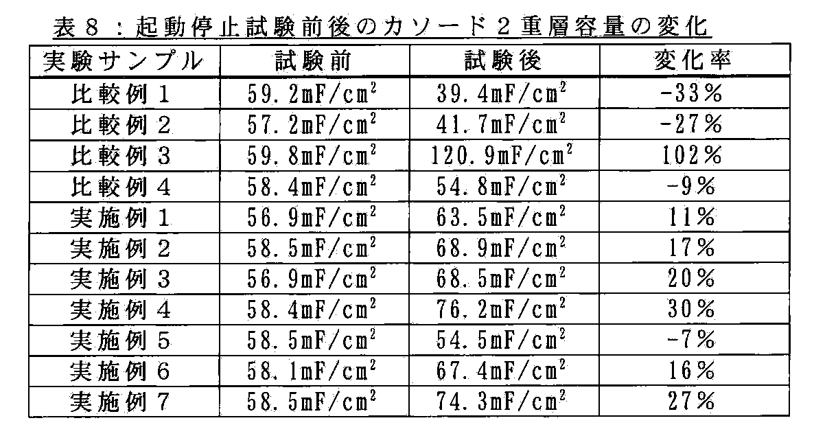
- Example 9 shows the results of determining the voltage deterioration rate from the difference between the generated voltage after the test and the initial generation voltage. From these results, it was confirmed that the fuel cell using the anode-side catalyst composition according to the present invention can generate power even after 90 cycles of hydrogen depletion operation (polarization) simulation. In Example 1 and Example 8, 180 cycles were also examined.
- the cell voltage during each cycle of the hydrogen deficiency test (1, 30, 60 cycles) was measured as an index for judging the water electrolysis overvoltage of the anode.
- the cell voltage of 180 cycles was also measured.
- the results are shown in Table 10.
- Comparative Examples 1 and 2 in which a platinum-based catalyst is used for the anode, the cell voltage changes significantly, and in the iridium-based catalyst of the present invention, the cell voltage hardly changes. This is presumably because the water electrolysis overvoltage of the iridium-based catalyst is lower than that of platinum, so that water electrolysis is likely to occur and corrosion of the carbon of the fuel electrode is suppressed. Further, it was confirmed that when graphitized carbon black was used (Example 8), higher hydrogen deficiency (polarization) resistance was obtained.
Landscapes
- Chemical & Material Sciences (AREA)
- Chemical Kinetics & Catalysis (AREA)
- Electrochemistry (AREA)
- General Chemical & Material Sciences (AREA)
- Engineering & Computer Science (AREA)
- Materials Engineering (AREA)
- Manufacturing & Machinery (AREA)
- Sustainable Energy (AREA)
- Life Sciences & Earth Sciences (AREA)
- Sustainable Development (AREA)
- Thermal Sciences (AREA)
- Physics & Mathematics (AREA)
- Composite Materials (AREA)
- Fuel Cell (AREA)
- Inert Electrodes (AREA)
- Catalysts (AREA)
Abstract
Description
H2→2H++2e−(E0=0V) …(1)
O2+4H++4e−→2H2O(E0=1.23V) …(2)
H2O→ 1/2O2+2H++2e− …(3)
1/2C+H2O→ 1/2CO2+2H++2e− …(4)
反応(4)によるアノードの劣化は深刻であり、燃料電池を瞬時に使用不可能としてしまう危険性がある。特に、水電解の反応効率が悪い(反応過電圧が高い)場合、水電解反応(3)ではなく、触媒担体カーボンの腐食によりH+を作り出す反応(4)が起こりやすくなるため、アノードの劣化が大きくなる。
H2→ 2H++2e− …(1)
O2+4H++4e−→ 2H2O …(2)
1/2C+H2O→ 1/2CO2+2H++2e− …(4)
起動の際、アノードガス入口付近のアノードでは、水素が供給されるので、水素酸化反応(1)が起こり、対極のカソードのアノードガス入口付近に対向する位置では、既に空気(酸素)が存在するので、酸素還元反応(2)が起こり、アノードおよびカソードの上流部は通常の燃料電池の反応系が発生する。一方、アノードガス出口付近のアノードでは、停止時に供給された空気(酸素)が残存し且つ水素は未だ十分供給されていないので、酸素還元反応(2)が起こる。対極のカソードのアノードガス出口付近に対向する位置では、対応して酸化反応が生じるが、被酸化物としての水素が存在しないので、そこに存在する炭素が酸化される腐食反応(4)が起こる。すなわち、アノード下流部に対向する位置のカソードで炭素の腐食反応系が発生する。この現象が、起動停止時におけるカソード劣化の一因であると報告されている。(特許文献1)
燃料電池での非定常な運転(起動停止・燃料欠乏)による燃料電池の劣化を抑制しようとする先行技術が公知となっているが、いずれの先行技術も白金(Pt)触媒を使用することを前提としている。白金(Pt)は燃料電池のコストの大部分を占めているので、燃料電池を実用化するにはコスト低減の点で問題が残る。
燃料欠乏への対策として、水電解触媒を用いることが先行技術で提案されているが、それらの触媒は溶出しやすいため、水電解触媒のみで燃料電池を構成することが困難であるため実用化されておらず、それゆえに白金(Pt)触媒に添加して使用されている。
また、起動停止への対策も先行技術で提案されているが、さらなる改善が求められている。すなわち、起動停止耐性を向上させると初期出力が低下するといったトレードオフが存在するため、実用的な出力と起動停止耐久性を満足させるためには、コストを犠牲にしてカソード白金触媒担持量を増加させて実用的な出力を得るといった手段をとる必要がある。その結果、高い起動停止耐久性と低コストを満足することが困難となっている。
先行技術による、起動停止・燃料欠乏への対策は十分ではないため、システムによる燃料電池の保護が行われている。各種センサーによってガス圧力・電位などを詳細にモニターしながら制御することによって起動停止や燃料欠乏での劣化モードに陥らないようにしている。このような補機のコストおよび制御の複雑さによってシステム面からの対策は燃料電池のコスト低減を困難にしている。
これら問題の解決に対して、非定常な運転(起動停止・燃料欠乏)による燃料電池の劣化を改善でき、且つ低コストである技術が望まれている。
(1)導電材に触媒粒子を担持した触媒とイオン交換樹脂とを含む燃料電池用アノード側触媒組成物であって、該触媒粒子は、酸素還元能および水電解過電圧が共に白金より低く、かつ、水素酸化能を有する、金属、金属酸化物もしくは金属の部分的酸化物またはこれらの混合物からなることを特徴とする触媒組成物が提供される。
(2)前記金属が、イリジウム、ルテニウム、レニウム、パラジウムおよびロジウムからなる群より選択された、(1)に記載の触媒組成物が提供される。
(3)前記触媒粒子が前記金属を含み、かつ、該金属の平均結晶子サイズが2nm~20nmの範囲内にある、(1)または(2)に記載の触媒組成物が提供される。
(4)前記金属の単位質量当たりの水素吸着領域の電荷量(QH)が15.0~65.0C/mg(金属)の範囲内にある、(1)~(3)のいずれかに記載の触媒組成物が提供される。
(5)前記触媒粒子が前記金属と前記金属酸化物または前記金属の部分的酸化物とを質量比1:10~10:1の範囲内で含む、(1)~(4)のいずれかに記載の触媒組成物が提供される。
(6)前記触媒粒子のX線光電子分光装置(XPS)スペクトルのIr4f7/2におけるピークが60.8~61.4(eV)の間に含まれる(1)~(5)のいずれかに記載の触媒組成物が提供される。
(7)前記導電材が、50m2/g以上300m2/g以下のBET比表面積を有する高黒鉛化度カーボンブラックである、(1)~(6)のいずれかに記載の触媒組成物が提供される。
(8)高分子電解質膜の片面にアノード用触媒層を、その反対面にカソード用触媒層を接合してなる固体高分子形燃料電池用膜電極接合体(MEA)であって、該アノード用触媒層が(1)~(7)のいずれかに記載の触媒組成物を含んでなるMEAが提供される。
(9)カソードでのPt担持量が0.2mg/cm2以下である(8)に記載のMEAが提供される。
本発明により、燃料電池の作動中に供給される水素が不足した場合でも、触媒の溶出問題が解決されるため、白金触媒を使用せずアノードの劣化を防止することが可能となる。
また、本発明により、燃料電池の起動停止時におけるアノードおよびカソードの劣化を軽減することが可能となる。この効果により、大幅なカソードの耐久性向上が図れ、カソードの白金触媒担持量の低減を行うことが可能となり、燃料電池の低コスト化を行うことができる。
本発明により、燃料欠乏(転極)や起動停止といった燃料電池の主たる劣化原因を根本から解決できる。したがって、従来システムによって保護していた部分を削減することができ、それによるシステム全体のコストダウンも得られる。
H2→2H++2e−(E0=0V) ・・・[1]
O2+4H++4e−→2H2O(E0=1.23V) ・・・[2]
H2O→ 1/2O2+2H++2e− ・・・[3]
この結果として、アノードの劣化を抑制することができる。
1/2C+H2O→ 1/2CO2+2H++2e− ・・・[4]
水電解の反応[3]の反応効率が悪い(反応過電圧が高い)場合、水電解反応[3]ではなく、触媒担体カーボンの腐食によりH+を作り出す反応[4]が起こりやすくなるため、アノードの劣化が大きくなる。
本発明では、水電解時の酸素発生過電圧が白金よりも低い触媒を使用するため、燃料欠乏時のアノード電位の上昇を抑えることができる。すなわち、燃料欠乏時に発生するアノードでの水電解反応[3]をスムーズに行うことによって、アノード(に含まれる触媒担体カーボン)の腐食によりH+を作り出す反応[4]が起こりにくくなり、結果としてアノードの劣化を抑制することができる。
O2+4H++4e−→ 2H2O ・・・[2]
本発明のアノード触媒において、酸素還元能が白金より低いことにより、起動停止時における燃料電池の劣化を軽減することが可能となる。
1/2C+H2O→ 1/2CO2+2H++2e− ・・・[4]
本発明では、アノードに酸素還元活性の低い触媒を使用してアノードでの酸素還元反応[2]を抑制することで、起動停止時のカソード腐食反応[4]の誘引を抑制し、燃料電池の劣化を軽減することが可能となる。
電池評価のために、カーボンブラックにイリジウム又はその酸化物を担持させた触媒を用意した。還元雰囲気下で熱処理したAシリーズと、酸化雰囲気下で熱処理したBシリーズとを用意した。また、市販品をベースとしたRシリーズも用意した。電池評価に用いた触媒の詳細な作製手順を以下に示す。
まず、Ir0.6gを含む塩化イリジウム(VI)酸水和物を200mlのn−ブタノールに溶解した溶液を調製した。一方、担体となるカーボンブラック(ケッチェンブラックインターナショナル社製、商品名:ケッチェンブラックEC)1.4gを300mLのn−ブタノールに良く分散させた分散液を調製した。続いて、カーボンブラック分散液を攪拌している所へ、塩化イリジウム(VI)酸水和物溶液を加えてスラリーを調製した。該スラリーに超音波を10分間照射した後、80℃で攪拌しながら塩化イリジウム(VI)酸水和物をカーボンブラックに含浸し、同温度にて約10時間攪拌しながら乾固することにより黒色の粉末を得た。得られた粉末をメノウ乳鉢にて粉砕し、これを水素ガス10%および窒素ガス90%よりなる混合ガス流通下、200℃から800℃の範囲内における所定の温度で2時間熱処理を行い、カーボン担持イリジウム触媒を作製した。熱処理の温度を200℃、400℃、600℃、800℃としたものをそれぞれ触媒A1、触媒A2、触媒A3、触媒A4とした。
得られた触媒A1を酸化雰囲気下で熱処理して、Bシリーズの触媒を作製した。触媒A1を酸素ガス20%および窒素ガス80%よりなる混合ガス流通下、100℃から300℃で1時間熱処理を行い、カーボン担持酸化イリジウム触媒を作製した。なお、300℃で酸化処理を行う際には、昇温の過程で発生する熱により試料が燃焼し、回収不能となるため、酸素ガス濃度を5%として300℃まで昇温した後、酸素ガス濃度を20%に増大して1hの酸化処理を施した。熱処理の温度を100℃、200℃、300℃としたものをそれぞれ触媒B1、触媒B2、触媒B3とした。
まず、Ir0.6gを含む塩化イリジウム(VI)酸水和物を200mlのn−ブタノールに溶解した溶液を調製した。一方、担体となる黒鉛化カーボンブラックは、カーボンブラック(ケッチェンブラックインターナショナル社製、商品名:ケッチェンブラックEC)を2500℃にて処理することにより黒鉛化させて準備した。黒鉛化カーボンブラック1.4gを300mLのn−ブタノールに良く分散させた分散液を調製した。続いて、カーボンブラック分散液を攪拌している所へ、塩化イリジウム(VI)酸水和物溶液を加えてスラリーを調製した。該スラリーに超音波を10分間照射した後、80℃で攪拌しながら塩化イリジウム(VI)酸水和物をカーボンブラックに含浸し、同温度にて約10時間攪拌しながら乾固することにより黒色の粉末を得た。得られた粉末をメノウ乳鉢にて粉砕し、これを水素ガス10%および窒素ガス90%よりなる混合ガス流通下、200℃で2時間熱処理を行い、カーボン担持イリジウム触媒を作製し、触媒C1とした。
市販品ベースの触媒として、HP Iridium on VulcanXC72(BASF Fuel Cell,Inc社製)を採用した(触媒R1)。これは、カーボンブラックVulcanXC72を担体とし、40%イリジウムを担持させたものである。また、R1を水素ガス10%および窒素ガス90%よりなる混合ガス流通下、800℃にて2時間熱処理を行い、カーボン担持イリジウム触媒(触媒R2)を作製した。
XRD分析を用いて、作製された触媒の結晶構造、粒子サイズ等について、調査を行った。XRD測定は、下記の連続スキャン(測定角度の広い方)およびステップスキャン(測定角度の狭い方)条件で行った。
装置:RINT2000((株)リガク)
X線:ターゲットCu、電圧40kV、電流80mA
連続スキャン条件: スキャン速度 2°/min;サンプリング幅 0.02°
ステップスキャン条件: 計測時間 5s;ステップ幅 0.02°。

上記で得られた触媒および比較用の触媒を用いて、電池評価用の膜電極接合体(MEA)を作製した。膜電極接合体の詳細な作製手順を以下に示す。
各比較例、実施例ごとに異なるアノード側カーボン担持触媒を採用した。比較例1、2および5では、ケッチェンブラックを担体とする50%白金担持カーボンTEC10E50E(触媒P:田中貴金属工業(株)製)を採用した。比較例3では、VulcanXC72を担体とする40%イリジウム担持カーボンHP Iridium on VulcanXC72(触媒R1:BASF Fuel Cell,Inc)を採用した。比較例4では、前記触媒B3を採用した。実施例1~9では、前記触媒A1~A4、B1、B2、C1およびR2を採用した。
固形分濃度が9wt%となるように、それぞれのカーボン担持触媒をアルコールと混合した。次に、各混合液をイオン交換樹脂溶液(パーフルオロスルホン酸電解質溶液(SE20142);デュポン社製)に、イオン交換樹脂溶液が担体カーボンに対して1.0の質量比率になるように、加えた。こうして調製された液体に超音波照射を行い、触媒担持カーボンを分散させ塗工液を作製した。
得られた塗工液を貴金属担持量が表2に示す所定量となるように各々厚さ200μmのPTFEシートに塗布・乾燥し、アノード電極層を形成した。
表2に、各比較例、実施例におけるアノード称呼、アノード触媒種類、触媒金属担持量を示す。
比較例1~4、実施例1~8において、カソードにはPRIMEA(登録商標)#5580(Pt担持量0.4mg/cm2:ジャパンゴアテックス(株)製)を採用した。
比較例5、実施例9において、カソードにはPRIMEA(登録商標)#5580(Pt担持量0.2mg/cm2:ジャパンゴアテックス(株)製)を採用した。PRIMEA(登録商標)#5580は、高比表面積カーボン仕様となっているため、Pt担持量を0.2mg/cm2と低減しても十分な初期特性が得られる。
全ての比較例、実施例において、電解質膜にはGORE−SELECT(登録商標)20K(ジャパンゴアテックス(株)製)を採用した。電解質膜は大きさ15×15cm、厚さ20μmのものを用意した。上記のアノード、カソードおよび電解質膜から、熱プレスを行いデカール法にて膜電極接合体(MEA)を作製した。

撥水化カーボンペーパー(CARBEL(登録商標)CNW10A:ジャパンゴアテックス(株)製)2枚の間に各膜電極接合体を配置して発電セルに組み込み、常圧にてアノード側に水素(利用率80%),カソード側に空気(利用率40%)を供給し、セル温度80℃にて電流密度0.2A/cm2、0.5A/cm2、1.0A/cm2での初期発電試験を実施した。またガス露点は高加湿条件として、アノード・カソード共に露点80℃のガスを供給した。また低加湿条件として、アノード・カソード共に露点55℃のガスを供給した。低加湿条件の場合は50kPaの背圧をかけた。そこで得られた電圧値を表3、4に示す。これらの結果から、本発明によるアノード側触媒組成物を用いた燃料電池が、高加湿条件下および低加湿条件下ともに、実用可能であることが確認された。


前述のXRD解析に基づいて、本発明の触媒組成物は2.0nm~20nmの平均結晶子サイズを有することが判明した。これに加えて、アノード触媒の2.0nmより小さい微粒子の存在を確認する目的で以下のような電気化学評価を実施した。アノードに露点80℃の窒素ガスを供給し、カソードに露点80℃の水素ガスを供給した。電圧が安定した後、ポテンショスタットを用いアノードを作用極としてサイクリックボルタンメトリーを上限電位は1.2V、下限電位は0.05V、走査速度は100mV/sの条件にて行い、3サイクル目のデータを用いた。水素吸着領域の電荷量は図3の斜線部分のQH(水素吸着電気量)より求め、x軸の最大値は0.35V付近で傾きが0となるときの値とし、二重層容量部分は除いた。得られた電荷量をアノード金属質量で割り、金属質量あたり当たりの電荷量の値を求めた。そこで得られた値を表5に示す。金属質量あたり当たりの電荷量は概ね触媒粒子の平均結晶子サイズと相関関係を有すると考えられる。すなわち、平均結晶子サイズが小さいほど、触媒表面積が大きくなり、金属質量あたり当たりの電荷量が増すと考えられる。XRDに基づく平均結晶子サイズと比較すると、触媒組成物の平均結晶子サイズが2nm~20nmの場合、前記金属の単位質量当たりの水素吸着領域の電荷量(QH)は、15.0~65.0C/mg(金属)の範囲に相当する。

撥水化カーボンペーパー(CARBEL(登録商標)CNW10A:ジャパンゴアテックス(株)製)2枚の間に各膜電極接合体を配置して発電セルに組み込み、常圧にてカソード側に水素(利用率80%),アノード側に酸素(利用率40%)を供給し、セル温度80℃にて電流密度0.1A/cm2での初期発電試験を実施した。またガス露点はアノード・カソード共に露点80℃のガスを供給した。そこで得られた抵抗補正後の電圧値を表6に示す。この結果から、本発明のイリジウム系触媒(実施例1~7)は白金系触媒(比較例1、2)と同様に酸素還元能を有するが、得られた電圧値は白金系触媒のものより低いことが分かる。すなわち、イリジウム系触媒は、白金よりも低い酸素還元能を有しており、これにより起動停止時の劣化が抑えられる。

撥水化カーボンペーパー(CARBEL(登録商標)CNW20B:ジャパンゴアテックス(株)製)2枚の間に各膜電極接合体を配置して発電セルに組み込み、常圧にてアノード側に水素(利用率83%),カソード側に空気(利用率50%)を供給し、セル温度80℃にて起動停止発電試験を実施した。またガス露点はアノード・カソード共に露点70℃のガスを供給した。起動停止評価手順について説明する。まず通常の初期発電特性評価を電流密度0.3A/cm2、0.8A/cm2、1.4A/cm2にて行い初期発電電圧を得た後、アノード側に空気を供給し、強制的に発電停止を行ったのち再度水素を供給して発電(起動)を行う。この起動停止サイクルを1000回実施した起動停止運転を模擬する加速試験とした。その後、通常の発電特性評価を電流密度0.3A/cm2、0.8A/m2、1.4A/cm2にて行い試験後の発電電圧を得た。そこで得られた試験後と初期の電圧の差から電圧劣化率を求めた結果を表7に示す。これらの結果から、本発明によるアノード側触媒組成物を用いた燃料電池が、起動停止サイクルを1000回実施した後でも、発電可能であり、かつ高い耐久性を示すことが確認された。これらの結果から、本発明によるアノード側触媒組成物を用いた燃料電池は、カソード白金担持量が0.2mg/cm2以下であっても(実施例9)、起動停止サイクルを1000回実施した後もまだ、十分発電可能であり、かつ高い耐久性を示すことが確認された。この結果はカソード担持量低減によるコスト低減の可能性を示唆するものである。

撥水化カーボンペーパー(CARBEL(登録商標)CNW10A:ジャパンゴアテックス(株)製)2枚の間に各膜電極接合体を配置して発電セルに組み込み、常圧にてアノード側に水素(利用率67%),カソード側に空気(利用率50%)を供給し、ガス露点はアノード・カソード共に露点70℃のガスを供給した。セル温度70℃にて発電試験を実施し、電流密度0.2A/cm2、0.5A/cm2、1.0A/cm2での初期の発電電圧を得た。水素欠乏評価は、発電試験後に、アノード側に窒素を供給し、アノードガスを水素から窒素に置換した。その状態にて、電流密度0.2A/cm2でアノード側に30秒間電流印加/開回路運転30秒保持を1サイクルとして90サイクルを実施し水素欠乏運転(転極)を模擬する加速試験とした。その後、通常の発電特性評価を行い、電流密度0.2A/cm2、0.5A/cm2での試験後の発電電圧を得た。試験後と初期の発電電圧の差から電圧劣化率を求めた結果を表9に示す。これらの結果から、本発明によるアノード側触媒組成物を用いた燃料電池が、水素欠乏運転(転極)模擬を90サイクル経た後でも、発電可能であることが確認された。また、実施例1と実施例8においては、180サイクルの検討も実施した。


X線光電子分光装置(XPS)を用い、調製した各種触媒のIr4fピークを測定した。線源にMg Kα線を用い、管電圧10kV、管電流20mAにて測定を行った。その結果によれば、Ir4fピークトップの位置は触媒によって異なり、Ir4f7/2のピークは60.8~61.5eVの範囲に現れた。その結果を表11に示す。これらのピークはIrの酸化数が大きいほど高エネルギー側へシフトし、酸化イリジウムのピークは金属イリジウムよりも0.5~1.5eV 高エネルギー側へ現れる。酸化処理を施した触媒B1、B3の値は、酸化処理を施していない触媒A4と比較して高エネルギー側へIr4fピークが現れ、酸素処理温度が高いほどシフト量が大きいことから、Ir粒子の酸化が進んでいると考えられる。これらの結果から、Ir4f7/2ピークが60.8~61.4(eV)の間に含まれる酸化状態を持つIr粒子が最適であると考えられる。ただし、金属の粒子サイズが数ナノメートル程度と微細な場合、粒子の電子状態はバルクの電子状態とは異なることも知られている。このことに起因して、金属粒子が小さい程XPSのピークは高エネルギー側へ数eVシフトすることが報告されている(参考文献1、2、3)。本発明におけるIr触媒についても、Ir粒子サイズが小さい場合、XPSのピークはIrの酸化によるシフトに加えて、粒子サイズ効果により、高エネルギー側へのシフトが起きると考えられる。
参考文献1:Y.Takasu et al.,Chem.Phys.Lett.,108,384(1984)
参考文献2:Y.Takasu et al.,Electrochim.Acta,41,2595(1996)
参考文献3:A.Fritsch et al.,Surface Science,145,L517(1984)

Claims (9)
- 導電材に触媒粒子を担持した触媒とイオン交換樹脂とを含む燃料電池用アノード側触媒組成物であって、該触媒粒子は、酸素還元能および水電解過電圧が共に白金より低く、かつ、水素酸化能を有する、金属、金属酸化物もしくは金属の部分的酸化物またはこれらの混合物からなることを特徴とする触媒組成物。
- 前記金属が、イリジウム、ルテニウム、レニウム、パラジウムおよびロジウムからなる群より選択された、請求項1に記載の触媒組成物。
- 前記触媒粒子が前記金属を含み、かつ、該金属の平均結晶子サイズが2nm~20nmの範囲内にある、請求項1または2に記載の触媒組成物。
- 前記金属の単位質量当たりの水素吸着領域の電荷量(QH)が15.0~65.0C/mg(金属)の範囲内にある、請求項1~3のいずれか1項に記載の触媒組成物。
- 前記触媒粒子が前記金属と前記金属酸化物または前記金属の部分的酸化物とを質量比1:10~10:1の範囲内で含む、請求項1~4のいずれか1項に記載の触媒組成物。
- 前記触媒粒子のX線光電子分光装置(XPS)スペクトルのIr4f7/2におけるピークが60.8~61.4(eV)の間に含まれる請求項1~5のいずれか1項に記載の触媒組成物。
- 前記導電材が、50m2/g以上300m2/g以下のBET比表面積を有する高黒鉛化度カーボンブラックである、請求項1~6のいずれか1項に記載の触媒組成物。
- 高分子電解質膜の片面にアノード用触媒層を、その反対面にカソード用触媒層を接合してなる固体高分子形燃料電池用膜電極接合体(MEA)であって、該アノード用触媒層が請求項1~7のいずれか1項に記載の触媒組成物を含んでなるMEA。
- カソードでのPt担持量が0.2mg/cm2以下である請求項8に記載のMEA。
Priority Applications (5)
| Application Number | Priority Date | Filing Date | Title |
|---|---|---|---|
| KR1020117025288A KR101823158B1 (ko) | 2009-04-27 | 2010-04-22 | 연료 전지용 애노드측 촉매 조성물 및 고체 고분자형 연료 전지용 막전극 접합체(mea) |
| CA2758432A CA2758432C (en) | 2009-04-27 | 2010-04-22 | Anode-side catalyst composition for fuel cell and membrane electrode assembly (mea) for polymer electrolyte fuel cell |
| US13/263,779 US20120064435A1 (en) | 2009-04-27 | 2010-04-22 | Anode-Side Catalyst Composition For Fuel Cell and Membrane Electrode Assembly (MEA) For Solid Polymer-Type Fuel Cell |
| EP10769817.7A EP2426763B1 (en) | 2009-04-27 | 2010-04-22 | Anode-side catalyst composition for fuel cell and membrane electrode assembly (mea) for solid polymer-type fuel cell |
| CN201080019317.XA CN102422472B (zh) | 2009-04-27 | 2010-04-22 | 燃料电池用阳极侧催化剂组合物及固体高分子型燃料电池用膜电极接合体(mea) |
Applications Claiming Priority (2)
| Application Number | Priority Date | Filing Date | Title |
|---|---|---|---|
| JP2009108331 | 2009-04-27 | ||
| JP2009-108331 | 2009-04-27 |
Publications (1)
| Publication Number | Publication Date |
|---|---|
| WO2010126119A1 true WO2010126119A1 (ja) | 2010-11-04 |
Family
ID=43032263
Family Applications (1)
| Application Number | Title | Priority Date | Filing Date |
|---|---|---|---|
| PCT/JP2010/057638 Ceased WO2010126119A1 (ja) | 2009-04-27 | 2010-04-22 | 燃料電池用アノード側触媒組成物および固体高分子形燃料電池用膜電極接合体(mea) |
Country Status (7)
| Country | Link |
|---|---|
| US (1) | US20120064435A1 (ja) |
| EP (1) | EP2426763B1 (ja) |
| JP (1) | JP2010277995A (ja) |
| KR (1) | KR101823158B1 (ja) |
| CN (1) | CN102422472B (ja) |
| CA (1) | CA2758432C (ja) |
| WO (1) | WO2010126119A1 (ja) |
Families Citing this family (16)
| Publication number | Priority date | Publication date | Assignee | Title |
|---|---|---|---|---|
| JP5755833B2 (ja) * | 2009-08-06 | 2015-07-29 | 日産自動車株式会社 | 燃料電池用アノード触媒層 |
| JP5755124B2 (ja) * | 2011-12-01 | 2015-07-29 | 株式会社キャタラー | 固体高分子形燃料電池用カソード触媒の製造方法 |
| US9698428B2 (en) | 2015-02-04 | 2017-07-04 | Nissan North America, Inc. | Catalyst support particle structures |
| US9871256B2 (en) | 2015-02-04 | 2018-01-16 | Nissan North America, Inc. | Fuel cell electrode having non-ionomer proton-conducting material |
| WO2018039267A1 (en) * | 2016-08-26 | 2018-03-01 | California Institute Of Technology | Electrolysis electrode and methods of manufacture and using same in water purification system |
| GB201719463D0 (en) * | 2017-11-23 | 2018-01-10 | Johnson Matthey Fuel Cells Ltd | Catalyst |
| KR102035769B1 (ko) | 2018-03-26 | 2019-10-24 | 한국과학기술연구원 | 고체산화물연료전지의 연료극용 나노촉매 및 이의 제조방법 |
| JP6727266B2 (ja) | 2018-09-18 | 2020-07-22 | 株式会社キャタラー | 燃料電池用アノード触媒層及びそれを用いた燃料電池 |
| JP6727264B2 (ja) * | 2018-09-18 | 2020-07-22 | 株式会社キャタラー | 燃料電池用アノード触媒層及びそれを用いた燃料電池 |
| JP6727265B2 (ja) | 2018-09-18 | 2020-07-22 | 株式会社キャタラー | 燃料電池用アノード触媒層及びそれを用いた燃料電池 |
| JP6727263B2 (ja) | 2018-09-18 | 2020-07-22 | 株式会社キャタラー | 燃料電池用アノード触媒層及びそれを用いた燃料電池 |
| CN109713330B (zh) * | 2018-11-13 | 2020-07-24 | 厦门大学 | 燃料电池阳极催化剂及其制备方法 |
| CN111244486A (zh) * | 2018-11-28 | 2020-06-05 | 中国科学院大连化学物理研究所 | 一种石墨型氮化碳和碳复合载体负载Ir催化剂的制备及应用 |
| KR102829803B1 (ko) * | 2019-03-28 | 2025-07-03 | 현대자동차주식회사 | 전자절연층이 도입된 막-전극 접합체의 전해질막 및 이의 제조방법 |
| WO2020264112A1 (en) | 2019-06-25 | 2020-12-30 | California Institute Of Technology | Reactive electrochemical membrane for wastewater treatment |
| WO2022132662A1 (en) | 2020-12-14 | 2022-06-23 | California Institute Of Technology | "super bubble" electro-photo hybrid catalytic system for advanced treatment of organic wastewater |
Citations (11)
| Publication number | Priority date | Publication date | Assignee | Title |
|---|---|---|---|---|
| JP2001357857A (ja) | 2000-06-12 | 2001-12-26 | Asahi Glass Co Ltd | 固体高分子型燃料電池及びその製造方法 |
| JP2003508877A (ja) | 1999-08-23 | 2003-03-04 | バラード パワー システムズ インコーポレイティド | 電圧反転に対する耐性を得るための燃料電池のアノード構造 |
| JP2004022503A (ja) | 2002-06-20 | 2004-01-22 | Tanaka Kikinzoku Kogyo Kk | 高分子固体電解質形燃料電池の燃料極 |
| US6855453B2 (en) | 2002-12-30 | 2005-02-15 | Utc Fuel Cells, Llc | Fuel cell having a corrosion resistant and protected cathode catalyst layer |
| WO2005049199A1 (en) | 2003-10-29 | 2005-06-02 | Umicore Ag & Co Kg | Precious metal oxide catalyst for water electrolysis |
| JP2005270687A (ja) | 2004-03-22 | 2005-10-06 | Nissan Motor Co Ltd | 触媒担持炭素材およびその製造方法 |
| JP2007115668A (ja) * | 2005-09-26 | 2007-05-10 | Toyota Motor Corp | 微粒子担持カーボン粒子およびその製造方法ならびに燃料電池用電極 |
| JP2007222732A (ja) * | 2006-02-22 | 2007-09-06 | Nissan Motor Co Ltd | 電極触媒 |
| JP2007265734A (ja) * | 2006-03-28 | 2007-10-11 | Toppan Printing Co Ltd | 燃料電池用触媒電極、その製造方法、燃料電池用高分子電解質膜・電極接合体及び燃料電池 |
| JP2008036539A (ja) * | 2006-08-07 | 2008-02-21 | National Institute Of Advanced Industrial & Technology | 一酸化炭素の電気化学的酸化用触媒 |
| JP2008293698A (ja) * | 2007-05-22 | 2008-12-04 | Permelec Electrode Ltd | ガス拡散電極とその製造方法、及び当該ガス拡散電極を用いる燃料電池及び食塩電解セル |
Family Cites Families (9)
| Publication number | Priority date | Publication date | Assignee | Title |
|---|---|---|---|---|
| US6638413B1 (en) * | 1989-10-10 | 2003-10-28 | Lectro Press, Inc. | Methods and apparatus for electrolysis of water |
| JPH1050321A (ja) * | 1996-07-30 | 1998-02-20 | Toyota Central Res & Dev Lab Inc | メタノール燃料電池用アノード触媒 |
| JPH10189002A (ja) * | 1996-12-27 | 1998-07-21 | Tokyo Gas Co Ltd | 燃料電池用電極及びその製造方法 |
| US6660680B1 (en) * | 1997-02-24 | 2003-12-09 | Superior Micropowders, Llc | Electrocatalyst powders, methods for producing powders and devices fabricated from same |
| US6967183B2 (en) * | 1998-08-27 | 2005-11-22 | Cabot Corporation | Electrocatalyst powders, methods for producing powders and devices fabricated from same |
| US6331694B1 (en) * | 1999-12-08 | 2001-12-18 | Lincoln Global, Inc. | Fuel cell operated welder |
| US20040013935A1 (en) * | 2002-07-19 | 2004-01-22 | Siyu Ye | Anode catalyst compositions for a voltage reversal tolerant fuel cell |
| KR100738062B1 (ko) * | 2006-05-16 | 2007-07-10 | 삼성에스디아이 주식회사 | 막 전극 접합체 및 이를 이용한 연료전지 |
| KR20110073382A (ko) * | 2008-02-25 | 2011-06-29 | 나노머티어리얼스 디스커버리 코포레이션 | 선택투과성 막이 없는 직접 연료 전지 및 이의 구성요소 |
-
2010
- 2010-04-22 JP JP2010098732A patent/JP2010277995A/ja active Pending
- 2010-04-22 US US13/263,779 patent/US20120064435A1/en not_active Abandoned
- 2010-04-22 CA CA2758432A patent/CA2758432C/en active Active
- 2010-04-22 WO PCT/JP2010/057638 patent/WO2010126119A1/ja not_active Ceased
- 2010-04-22 CN CN201080019317.XA patent/CN102422472B/zh not_active Expired - Fee Related
- 2010-04-22 EP EP10769817.7A patent/EP2426763B1/en not_active Not-in-force
- 2010-04-22 KR KR1020117025288A patent/KR101823158B1/ko not_active Expired - Fee Related
Patent Citations (11)
| Publication number | Priority date | Publication date | Assignee | Title |
|---|---|---|---|---|
| JP2003508877A (ja) | 1999-08-23 | 2003-03-04 | バラード パワー システムズ インコーポレイティド | 電圧反転に対する耐性を得るための燃料電池のアノード構造 |
| JP2001357857A (ja) | 2000-06-12 | 2001-12-26 | Asahi Glass Co Ltd | 固体高分子型燃料電池及びその製造方法 |
| JP2004022503A (ja) | 2002-06-20 | 2004-01-22 | Tanaka Kikinzoku Kogyo Kk | 高分子固体電解質形燃料電池の燃料極 |
| US6855453B2 (en) | 2002-12-30 | 2005-02-15 | Utc Fuel Cells, Llc | Fuel cell having a corrosion resistant and protected cathode catalyst layer |
| WO2005049199A1 (en) | 2003-10-29 | 2005-06-02 | Umicore Ag & Co Kg | Precious metal oxide catalyst for water electrolysis |
| JP2005270687A (ja) | 2004-03-22 | 2005-10-06 | Nissan Motor Co Ltd | 触媒担持炭素材およびその製造方法 |
| JP2007115668A (ja) * | 2005-09-26 | 2007-05-10 | Toyota Motor Corp | 微粒子担持カーボン粒子およびその製造方法ならびに燃料電池用電極 |
| JP2007222732A (ja) * | 2006-02-22 | 2007-09-06 | Nissan Motor Co Ltd | 電極触媒 |
| JP2007265734A (ja) * | 2006-03-28 | 2007-10-11 | Toppan Printing Co Ltd | 燃料電池用触媒電極、その製造方法、燃料電池用高分子電解質膜・電極接合体及び燃料電池 |
| JP2008036539A (ja) * | 2006-08-07 | 2008-02-21 | National Institute Of Advanced Industrial & Technology | 一酸化炭素の電気化学的酸化用触媒 |
| JP2008293698A (ja) * | 2007-05-22 | 2008-12-04 | Permelec Electrode Ltd | ガス拡散電極とその製造方法、及び当該ガス拡散電極を用いる燃料電池及び食塩電解セル |
Non-Patent Citations (3)
| Title |
|---|
| LABOU ET AL., JOURNAL OF POWER SOURCES, vol. 185, 2008, pages 1073 - 1078 |
| MARSHALL ET AL., INTERNATIONAL JOURNAL OF HYDROGEN ENERGY, vol. 32, 2007, pages 2320 - 2324 |
| See also references of EP2426763A4 |
Also Published As
| Publication number | Publication date |
|---|---|
| KR20120026041A (ko) | 2012-03-16 |
| CA2758432A1 (en) | 2010-11-04 |
| KR101823158B1 (ko) | 2018-01-29 |
| EP2426763B1 (en) | 2017-01-11 |
| CN102422472B (zh) | 2015-02-11 |
| CN102422472A (zh) | 2012-04-18 |
| US20120064435A1 (en) | 2012-03-15 |
| EP2426763A1 (en) | 2012-03-07 |
| EP2426763A4 (en) | 2013-11-13 |
| JP2010277995A (ja) | 2010-12-09 |
| CA2758432C (en) | 2019-03-12 |
Similar Documents
| Publication | Publication Date | Title |
|---|---|---|
| KR101823158B1 (ko) | 연료 전지용 애노드측 촉매 조성물 및 고체 고분자형 연료 전지용 막전극 접합체(mea) | |
| JP7190462B2 (ja) | 膜電極接合体 | |
| US10847811B2 (en) | Catalyst particle, and electrode catalyst, electrolyte membrane-electrode assembly, and fuel cell using the same | |
| US9825307B2 (en) | Anode-side catalyst composition for fuel cells, and membrane electrode assembly (MEA) for solid polymer fuel cells which comprises same | |
| JP6482473B2 (ja) | アノード触媒層の使用 | |
| JP2006012476A (ja) | 燃料電池用膜−電極接合体 | |
| Liu et al. | Micro-protective layer for lifetime extension of solid polymer electrolyte water electrolysis | |
| JP5755833B2 (ja) | 燃料電池用アノード触媒層 | |
| JP5805924B2 (ja) | 電解質膜−電極接合体 | |
| JP2007188768A (ja) | 固体高分子型燃料電池 | |
| JP2007080694A (ja) | 燃料電池用電極触媒層、および、これを用いた燃料電池 | |
| JP2005317467A (ja) | 燃料電池用電極、およびこれを用いた燃料電池用mea | |
| CN100454623C (zh) | 燃料电池用膜-电极接合体以及使用其的燃料电池 | |
| JP2007128665A (ja) | 燃料電池用電極触媒層、および、それを用いた膜電極接合体の製造方法 | |
| HK1165095B (en) | Anode-side catalyst composition for fuel cell and membrane electrode assembly (mea) for solid polymer-type fuel cell | |
| HK1165095A (en) | Anode-side catalyst composition for fuel cell and membrane electrode assembly (mea) for solid polymer-type fuel cell | |
| Lim | Development and characterization of direct ethanol fuel cells using alkaline anion-exchange membranes | |
| Knupp | Design and development of highly active, nanoengineered, platinum based core-shell electrodes for proton exchange membrane fuel cells |
Legal Events
| Date | Code | Title | Description |
|---|---|---|---|
| WWE | Wipo information: entry into national phase |
Ref document number: 201080019317.X Country of ref document: CN |
|
| 121 | Ep: the epo has been informed by wipo that ep was designated in this application |
Ref document number: 10769817 Country of ref document: EP Kind code of ref document: A1 |
|
| WWE | Wipo information: entry into national phase |
Ref document number: 2758432 Country of ref document: CA |
|
| ENP | Entry into the national phase |
Ref document number: 20117025288 Country of ref document: KR Kind code of ref document: A |
|
| NENP | Non-entry into the national phase |
Ref country code: DE |
|
| WWE | Wipo information: entry into national phase |
Ref document number: 13263779 Country of ref document: US |
|
| REEP | Request for entry into the european phase |
Ref document number: 2010769817 Country of ref document: EP |
|
| WWE | Wipo information: entry into national phase |
Ref document number: 2010769817 Country of ref document: EP |