WO2010128542A1 - パラレル式ハイブリッド車の動力伝達機構 - Google Patents
パラレル式ハイブリッド車の動力伝達機構 Download PDFInfo
- Publication number
- WO2010128542A1 WO2010128542A1 PCT/JP2009/006187 JP2009006187W WO2010128542A1 WO 2010128542 A1 WO2010128542 A1 WO 2010128542A1 JP 2009006187 W JP2009006187 W JP 2009006187W WO 2010128542 A1 WO2010128542 A1 WO 2010128542A1
- Authority
- WO
- WIPO (PCT)
- Prior art keywords
- motor
- gear
- brake
- engine
- output shaft
- Prior art date
- Legal status (The legal status is an assumption and is not a legal conclusion. Google has not performed a legal analysis and makes no representation as to the accuracy of the status listed.)
- Ceased
Links
Images



Classifications
-
- B—PERFORMING OPERATIONS; TRANSPORTING
- B60—VEHICLES IN GENERAL
- B60K—ARRANGEMENT OR MOUNTING OF PROPULSION UNITS OR OF TRANSMISSIONS IN VEHICLES; ARRANGEMENT OR MOUNTING OF PLURAL DIVERSE PRIME-MOVERS IN VEHICLES; AUXILIARY DRIVES FOR VEHICLES; INSTRUMENTATION OR DASHBOARDS FOR VEHICLES; ARRANGEMENTS IN CONNECTION WITH COOLING, AIR INTAKE, GAS EXHAUST OR FUEL SUPPLY OF PROPULSION UNITS IN VEHICLES
- B60K6/00—Arrangement or mounting of plural diverse prime-movers for mutual or common propulsion, e.g. hybrid propulsion systems comprising electric motors and internal combustion engines
- B60K6/20—Arrangement or mounting of plural diverse prime-movers for mutual or common propulsion, e.g. hybrid propulsion systems comprising electric motors and internal combustion engines the prime-movers consisting of electric motors and internal combustion engines, e.g. HEVs
- B60K6/42—Arrangement or mounting of plural diverse prime-movers for mutual or common propulsion, e.g. hybrid propulsion systems comprising electric motors and internal combustion engines the prime-movers consisting of electric motors and internal combustion engines, e.g. HEVs characterised by the architecture of the hybrid electric vehicle
- B60K6/48—Parallel type
-
- B—PERFORMING OPERATIONS; TRANSPORTING
- B60—VEHICLES IN GENERAL
- B60K—ARRANGEMENT OR MOUNTING OF PROPULSION UNITS OR OF TRANSMISSIONS IN VEHICLES; ARRANGEMENT OR MOUNTING OF PLURAL DIVERSE PRIME-MOVERS IN VEHICLES; AUXILIARY DRIVES FOR VEHICLES; INSTRUMENTATION OR DASHBOARDS FOR VEHICLES; ARRANGEMENTS IN CONNECTION WITH COOLING, AIR INTAKE, GAS EXHAUST OR FUEL SUPPLY OF PROPULSION UNITS IN VEHICLES
- B60K6/00—Arrangement or mounting of plural diverse prime-movers for mutual or common propulsion, e.g. hybrid propulsion systems comprising electric motors and internal combustion engines
- B60K6/20—Arrangement or mounting of plural diverse prime-movers for mutual or common propulsion, e.g. hybrid propulsion systems comprising electric motors and internal combustion engines the prime-movers consisting of electric motors and internal combustion engines, e.g. HEVs
- B60K6/22—Arrangement or mounting of plural diverse prime-movers for mutual or common propulsion, e.g. hybrid propulsion systems comprising electric motors and internal combustion engines the prime-movers consisting of electric motors and internal combustion engines, e.g. HEVs characterised by apparatus, components or means specially adapted for HEVs
- B60K6/36—Arrangement or mounting of plural diverse prime-movers for mutual or common propulsion, e.g. hybrid propulsion systems comprising electric motors and internal combustion engines the prime-movers consisting of electric motors and internal combustion engines, e.g. HEVs characterised by apparatus, components or means specially adapted for HEVs characterised by the transmission gearings
- B60K6/365—Arrangement or mounting of plural diverse prime-movers for mutual or common propulsion, e.g. hybrid propulsion systems comprising electric motors and internal combustion engines the prime-movers consisting of electric motors and internal combustion engines, e.g. HEVs characterised by apparatus, components or means specially adapted for HEVs characterised by the transmission gearings with the gears having orbital motion
-
- B—PERFORMING OPERATIONS; TRANSPORTING
- B60—VEHICLES IN GENERAL
- B60K—ARRANGEMENT OR MOUNTING OF PROPULSION UNITS OR OF TRANSMISSIONS IN VEHICLES; ARRANGEMENT OR MOUNTING OF PLURAL DIVERSE PRIME-MOVERS IN VEHICLES; AUXILIARY DRIVES FOR VEHICLES; INSTRUMENTATION OR DASHBOARDS FOR VEHICLES; ARRANGEMENTS IN CONNECTION WITH COOLING, AIR INTAKE, GAS EXHAUST OR FUEL SUPPLY OF PROPULSION UNITS IN VEHICLES
- B60K6/00—Arrangement or mounting of plural diverse prime-movers for mutual or common propulsion, e.g. hybrid propulsion systems comprising electric motors and internal combustion engines
- B60K6/20—Arrangement or mounting of plural diverse prime-movers for mutual or common propulsion, e.g. hybrid propulsion systems comprising electric motors and internal combustion engines the prime-movers consisting of electric motors and internal combustion engines, e.g. HEVs
- B60K6/22—Arrangement or mounting of plural diverse prime-movers for mutual or common propulsion, e.g. hybrid propulsion systems comprising electric motors and internal combustion engines the prime-movers consisting of electric motors and internal combustion engines, e.g. HEVs characterised by apparatus, components or means specially adapted for HEVs
- B60K6/38—Arrangement or mounting of plural diverse prime-movers for mutual or common propulsion, e.g. hybrid propulsion systems comprising electric motors and internal combustion engines the prime-movers consisting of electric motors and internal combustion engines, e.g. HEVs characterised by apparatus, components or means specially adapted for HEVs characterised by the driveline clutches
- B60K6/387—Actuated clutches, i.e. clutches engaged or disengaged by electric, hydraulic or mechanical actuating means
-
- B—PERFORMING OPERATIONS; TRANSPORTING
- B60—VEHICLES IN GENERAL
- B60K—ARRANGEMENT OR MOUNTING OF PROPULSION UNITS OR OF TRANSMISSIONS IN VEHICLES; ARRANGEMENT OR MOUNTING OF PLURAL DIVERSE PRIME-MOVERS IN VEHICLES; AUXILIARY DRIVES FOR VEHICLES; INSTRUMENTATION OR DASHBOARDS FOR VEHICLES; ARRANGEMENTS IN CONNECTION WITH COOLING, AIR INTAKE, GAS EXHAUST OR FUEL SUPPLY OF PROPULSION UNITS IN VEHICLES
- B60K6/00—Arrangement or mounting of plural diverse prime-movers for mutual or common propulsion, e.g. hybrid propulsion systems comprising electric motors and internal combustion engines
- B60K6/20—Arrangement or mounting of plural diverse prime-movers for mutual or common propulsion, e.g. hybrid propulsion systems comprising electric motors and internal combustion engines the prime-movers consisting of electric motors and internal combustion engines, e.g. HEVs
- B60K6/50—Architecture of the driveline characterised by arrangement or kind of transmission units
- B60K6/54—Transmission for changing ratio
- B60K6/547—Transmission for changing ratio the transmission being a stepped gearing
-
- B—PERFORMING OPERATIONS; TRANSPORTING
- B60—VEHICLES IN GENERAL
- B60L—PROPULSION OF ELECTRICALLY-PROPELLED VEHICLES; SUPPLYING ELECTRIC POWER FOR AUXILIARY EQUIPMENT OF ELECTRICALLY-PROPELLED VEHICLES; ELECTRODYNAMIC BRAKE SYSTEMS FOR VEHICLES IN GENERAL; MAGNETIC SUSPENSION OR LEVITATION FOR VEHICLES; MONITORING OPERATING VARIABLES OF ELECTRICALLY-PROPELLED VEHICLES; ELECTRIC SAFETY DEVICES FOR ELECTRICALLY-PROPELLED VEHICLES
- B60L50/00—Electric propulsion with power supplied within the vehicle
- B60L50/10—Electric propulsion with power supplied within the vehicle using propulsion power supplied by engine-driven generators, e.g. generators driven by combustion engines
- B60L50/16—Electric propulsion with power supplied within the vehicle using propulsion power supplied by engine-driven generators, e.g. generators driven by combustion engines with provision for separate direct mechanical propulsion
-
- B—PERFORMING OPERATIONS; TRANSPORTING
- B60—VEHICLES IN GENERAL
- B60L—PROPULSION OF ELECTRICALLY-PROPELLED VEHICLES; SUPPLYING ELECTRIC POWER FOR AUXILIARY EQUIPMENT OF ELECTRICALLY-PROPELLED VEHICLES; ELECTRODYNAMIC BRAKE SYSTEMS FOR VEHICLES IN GENERAL; MAGNETIC SUSPENSION OR LEVITATION FOR VEHICLES; MONITORING OPERATING VARIABLES OF ELECTRICALLY-PROPELLED VEHICLES; ELECTRIC SAFETY DEVICES FOR ELECTRICALLY-PROPELLED VEHICLES
- B60L7/00—Electrodynamic brake systems for vehicles in general
- B60L7/10—Dynamic electric regenerative braking
- B60L7/18—Controlling the braking effect
-
- B—PERFORMING OPERATIONS; TRANSPORTING
- B60—VEHICLES IN GENERAL
- B60L—PROPULSION OF ELECTRICALLY-PROPELLED VEHICLES; SUPPLYING ELECTRIC POWER FOR AUXILIARY EQUIPMENT OF ELECTRICALLY-PROPELLED VEHICLES; ELECTRODYNAMIC BRAKE SYSTEMS FOR VEHICLES IN GENERAL; MAGNETIC SUSPENSION OR LEVITATION FOR VEHICLES; MONITORING OPERATING VARIABLES OF ELECTRICALLY-PROPELLED VEHICLES; ELECTRIC SAFETY DEVICES FOR ELECTRICALLY-PROPELLED VEHICLES
- B60L7/00—Electrodynamic brake systems for vehicles in general
- B60L7/24—Electrodynamic brake systems for vehicles in general with additional mechanical or electromagnetic braking
- B60L7/26—Controlling the braking effect
-
- B—PERFORMING OPERATIONS; TRANSPORTING
- B60—VEHICLES IN GENERAL
- B60K—ARRANGEMENT OR MOUNTING OF PROPULSION UNITS OR OF TRANSMISSIONS IN VEHICLES; ARRANGEMENT OR MOUNTING OF PLURAL DIVERSE PRIME-MOVERS IN VEHICLES; AUXILIARY DRIVES FOR VEHICLES; INSTRUMENTATION OR DASHBOARDS FOR VEHICLES; ARRANGEMENTS IN CONNECTION WITH COOLING, AIR INTAKE, GAS EXHAUST OR FUEL SUPPLY OF PROPULSION UNITS IN VEHICLES
- B60K6/00—Arrangement or mounting of plural diverse prime-movers for mutual or common propulsion, e.g. hybrid propulsion systems comprising electric motors and internal combustion engines
- B60K6/20—Arrangement or mounting of plural diverse prime-movers for mutual or common propulsion, e.g. hybrid propulsion systems comprising electric motors and internal combustion engines the prime-movers consisting of electric motors and internal combustion engines, e.g. HEVs
- B60K6/22—Arrangement or mounting of plural diverse prime-movers for mutual or common propulsion, e.g. hybrid propulsion systems comprising electric motors and internal combustion engines the prime-movers consisting of electric motors and internal combustion engines, e.g. HEVs characterised by apparatus, components or means specially adapted for HEVs
- B60K6/38—Arrangement or mounting of plural diverse prime-movers for mutual or common propulsion, e.g. hybrid propulsion systems comprising electric motors and internal combustion engines the prime-movers consisting of electric motors and internal combustion engines, e.g. HEVs characterised by apparatus, components or means specially adapted for HEVs characterised by the driveline clutches
- B60K2006/381—Arrangement or mounting of plural diverse prime-movers for mutual or common propulsion, e.g. hybrid propulsion systems comprising electric motors and internal combustion engines the prime-movers consisting of electric motors and internal combustion engines, e.g. HEVs characterised by apparatus, components or means specially adapted for HEVs characterised by the driveline clutches characterized by driveline brakes
-
- B—PERFORMING OPERATIONS; TRANSPORTING
- B60—VEHICLES IN GENERAL
- B60L—PROPULSION OF ELECTRICALLY-PROPELLED VEHICLES; SUPPLYING ELECTRIC POWER FOR AUXILIARY EQUIPMENT OF ELECTRICALLY-PROPELLED VEHICLES; ELECTRODYNAMIC BRAKE SYSTEMS FOR VEHICLES IN GENERAL; MAGNETIC SUSPENSION OR LEVITATION FOR VEHICLES; MONITORING OPERATING VARIABLES OF ELECTRICALLY-PROPELLED VEHICLES; ELECTRIC SAFETY DEVICES FOR ELECTRICALLY-PROPELLED VEHICLES
- B60L2200/00—Type of vehicles
- B60L2200/26—Rail vehicles
-
- B—PERFORMING OPERATIONS; TRANSPORTING
- B60—VEHICLES IN GENERAL
- B60L—PROPULSION OF ELECTRICALLY-PROPELLED VEHICLES; SUPPLYING ELECTRIC POWER FOR AUXILIARY EQUIPMENT OF ELECTRICALLY-PROPELLED VEHICLES; ELECTRODYNAMIC BRAKE SYSTEMS FOR VEHICLES IN GENERAL; MAGNETIC SUSPENSION OR LEVITATION FOR VEHICLES; MONITORING OPERATING VARIABLES OF ELECTRICALLY-PROPELLED VEHICLES; ELECTRIC SAFETY DEVICES FOR ELECTRICALLY-PROPELLED VEHICLES
- B60L2270/00—Problem solutions or means not otherwise provided for
- B60L2270/10—Emission reduction
- B60L2270/14—Emission reduction of noise
- B60L2270/145—Structure borne vibrations
-
- Y—GENERAL TAGGING OF NEW TECHNOLOGICAL DEVELOPMENTS; GENERAL TAGGING OF CROSS-SECTIONAL TECHNOLOGIES SPANNING OVER SEVERAL SECTIONS OF THE IPC; TECHNICAL SUBJECTS COVERED BY FORMER USPC CROSS-REFERENCE ART COLLECTIONS [XRACs] AND DIGESTS
- Y02—TECHNOLOGIES OR APPLICATIONS FOR MITIGATION OR ADAPTATION AGAINST CLIMATE CHANGE
- Y02T—CLIMATE CHANGE MITIGATION TECHNOLOGIES RELATED TO TRANSPORTATION
- Y02T10/00—Road transport of goods or passengers
- Y02T10/60—Other road transportation technologies with climate change mitigation effect
- Y02T10/62—Hybrid vehicles
-
- Y—GENERAL TAGGING OF NEW TECHNOLOGICAL DEVELOPMENTS; GENERAL TAGGING OF CROSS-SECTIONAL TECHNOLOGIES SPANNING OVER SEVERAL SECTIONS OF THE IPC; TECHNICAL SUBJECTS COVERED BY FORMER USPC CROSS-REFERENCE ART COLLECTIONS [XRACs] AND DIGESTS
- Y02—TECHNOLOGIES OR APPLICATIONS FOR MITIGATION OR ADAPTATION AGAINST CLIMATE CHANGE
- Y02T—CLIMATE CHANGE MITIGATION TECHNOLOGIES RELATED TO TRANSPORTATION
- Y02T10/00—Road transport of goods or passengers
- Y02T10/60—Other road transportation technologies with climate change mitigation effect
- Y02T10/70—Energy storage systems for electromobility, e.g. batteries
-
- Y—GENERAL TAGGING OF NEW TECHNOLOGICAL DEVELOPMENTS; GENERAL TAGGING OF CROSS-SECTIONAL TECHNOLOGIES SPANNING OVER SEVERAL SECTIONS OF THE IPC; TECHNICAL SUBJECTS COVERED BY FORMER USPC CROSS-REFERENCE ART COLLECTIONS [XRACs] AND DIGESTS
- Y02—TECHNOLOGIES OR APPLICATIONS FOR MITIGATION OR ADAPTATION AGAINST CLIMATE CHANGE
- Y02T—CLIMATE CHANGE MITIGATION TECHNOLOGIES RELATED TO TRANSPORTATION
- Y02T10/00—Road transport of goods or passengers
- Y02T10/60—Other road transportation technologies with climate change mitigation effect
- Y02T10/7072—Electromobility specific charging systems or methods for batteries, ultracapacitors, supercapacitors or double-layer capacitors
Definitions
- the present invention relates to a power transmission mechanism for a hybrid vehicle, and more particularly to a power transmission mechanism for a parallel hybrid vehicle that uses both engine and motor / generator power.
- Non-Patent Document 1 in recent years, in a commercial vehicle such as a truck, traveling with a load on the engine such as when starting or traveling on an uphill road in order to improve the fuel efficiency by reducing the engine load.
- a parallel hybrid system that sometimes uses the assistance of a motor has been proposed.
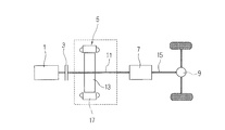
- the arrangement of the drive system of the hybrid system is as follows: engine 1, main clutch (single plate clutch) 3, motor (motor / generator) 5, transmission 7, and final reduction gear 9. It is arranged on the same axis.
- the rotor 13 of the motor 5 is attached to the engine drive shaft system 11 connected from the main clutch 3 to the transmission 7, and the propulsion shaft 15 is connected between the transmission 7 and the final gear 9.
- the hybrid system starts with only the driving force of the motor 5 with the clutch 3 disengaged, and synchronizes the rotation of the engine 1 and the motor 5 at a specified vehicle speed (about 5 to 6 km / h). 3 is connected to start running only with the engine 1.
- the engine 1 and the motor 5 are used together in accordance with the amount of depression of the accelerator pedal, and during deceleration or braking, the clutch 3 is disengaged depending on the situation.
- the motor 5 is reversely operated to apply a regenerative brake equivalent to an engine brake, and regenerative energy is stored in a battery.
- the power transmission mechanism of the hybrid system has a drawback in that mechanical loss occurs due to the influence of the magnet mounted on the rotor 13 when traveling only with the driving force of the engine 1. Further, if electricity is passed through the stator 17 of the motor 5 in order to cancel out such load loss, a new electrical loss is generated.
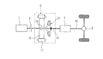
- Non-Patent Document 2 discloses a technique in which a clutch mechanism 21 including a dog clutch is mounted between the system 11 and the system 11.
- the power transmission mechanism of the hybrid system shown in FIG. 7 is assumed to be mounted on a small truck with a capacity of 2 to 3 tons.
- the strength of the dog clutch There are concerns about shortages and lack of durability.
- An object of the present invention is to provide a power transmission mechanism for a parallel hybrid vehicle that can be applied to a large-sized hybrid vehicle having a loading capacity exceeding 10 tons.
- the invention according to claim 1 has an engine, a main clutch, a motor / generator, a transmission, and a final reduction gear arranged on the same axis, and uses the power of the engine and the motor / generator together.
- a power transmission mechanism for a parallel hybrid vehicle wherein the motor drive shaft of the motor / generator that can be rotated separately from the engine drive shaft system connected to the transmission from the main clutch, and one end side of the motor output shaft
- a motor brake that is mounted and releases / fixes the motor output shaft
- a sun gear that is mounted between the other end side of the motor output shaft and the engine drive shaft system and is provided on the other end side of the motor output shaft
- An outer gear provided in the engine drive shaft system and having a gear ratio with the sun gear of 1: 1, a plurality of planetary gears meshing with the sun gear and the outer gear, and the planetary gear
- a planetary gear mechanism comprising a planetary carrier for picking up the revolving motion of the gear, and a gear brake mounted on one end side of the planetary carrier for releasing / fixing the planetary carrier, the main clutch and the gear brake being fixed, By releasing the motor brake, the driving force of the motor / generator is transmitted from the planetary gear mechanism to the engine drive shaft system and mixed with
- the motor output shaft is fixed and does not rotate. Therefore, mechanical loss and electrical loss can be reduced as compared with the conventional case, and the engine load is reduced. This has the advantage of improving fuel economy.
- both shafts can be smoothly connected and disconnected, and the planetary gear mechanism has sufficient strength. Therefore, it can be applied to a large truck that requires a large motor output.
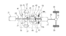
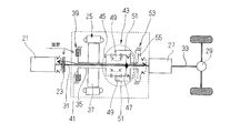
- FIG. 1 to 4 show a first embodiment of a power transmission mechanism for a parallel hybrid vehicle according to claim 1, and, similarly to the conventional example of FIG. 6, the arrangement of the drive system of the hybrid system according to this embodiment is also an engine. 21, a main clutch (single-plate clutch) 23, a motor (motor / generator) 25, a transmission 27, and a final reduction gear 29 are all arranged coaxially in this order. An engine drive shaft system 31 is connected from the main clutch 23 to the transmission 27, and a propulsion shaft 33 is connected between the transmission 27 and the final gear 29.
- reference numeral 35 denotes a motor output shaft attached to the rotor 37 of the motor 25, which is configured separately from the engine drive shaft system 31, and is rotatably supported by a motor body (not shown) via a bearing.
- a motor brake 39 for releasing / fixing the motor output shaft 35 is attached to one end of the motor output shaft 35 on the main clutch 23 side.
- the motor brake 39 has a structure such as a disc brake, for example, and the motor output shaft 35 is rotated by sandwiching a brake disc 41 provided on the motor output shaft 35 with a brake pad (not shown) or the like (fixing the motor brake 39).
- the motor output shaft 35 is fixed by being braked, and the braking of the motor output shaft 35 is released when the brake pad or the like is separated from the brake disc 41 (release of the motor brake 39).
- a planetary gear mechanism 43 is provided between the other end side of the motor output shaft 35 and the engine drive shaft system 31.
- the planetary gear mechanism 43 includes a sun gear 45 provided on the other end side of the motor output shaft 35, an outer gear 47 attached to the engine drive shaft system 31 so as to face the sun gear 45,
- the sun gear 45 and the outer gear 47 are made up of a plurality of planetary gears 49 and a planetary carrier 51 that picks up the revolving motion of the planetary gears 49.
- the sun gear 45 and the outer gear 47 have a pair of left and right differentials of a conventionally known differential device. It is formed in a shape like a side gear and is set to a gear ratio of 1: 1 with the same rotation radius. For this reason, as shown in the figure, the rotation shaft of the planetary gear 49 that is attached to the planetary carrier 51 is arranged at a right angle to the motor output shaft 35.
- a gear brake 53 for releasing / fixing the planetary carrier 51 to release / fix the revolution of the planetary gear 49 is provided.
- the gear brake 53 has a structure like a disc brake as an example, and a brake disc 55 provided on the other end side of the planetary gear 49 is sandwiched between brake pads (not shown) or the like (fixing of the gear brake 53).
- the rotation of the planetary carrier 51 is braked so that the revolution of the planetary gear 49 is fixed, and the braking of the planetary carrier 51 is released by separating the braking pad or the like from the brake disc 55 (releasing the gear brake 53).
- the planetary gear 49 returns so as to be able to revolve.
- the power transmission mechanism 57 is configured as described above, and the operation thereof will be described next.
- the main clutch 23 is connected and “fixed”, the brake disc 55 is sandwiched between brake pads and the gear brake 53 (planetary gear 49) is “fixed”, and the brake pads and the like are also fixed to the brake disc.
- the motor brake 39 (motor output shaft 35) is “released” away from the motor 41, the planetary gear 49 is restricted from revolving and can only rotate.
- the gear brake 53 (planetary carrier 51) is “fixed” as shown in FIG.
- the motor brake 39 motor output shaft 35
- the revolution of the planetary gear 49 is restricted, so that only the driving force of the motor 25 causes the sun gear 45, the planetary gear 49, and the outer gear 47 to move.
- the vehicle is transmitted from the engine drive shaft system 31 to the transmission via the drive force of the motor 25 alone. Then, if the main clutch 23 is connected at the specified vehicle speed as shown in FIG.
- the main clutch 23 is connected and “fixed”, the brake disc 41 is sandwiched between brake pads and the motor brake 39 (motor output shaft 35) is “fixed”, and the brake pads and the like are braked.
- the gear brake 53 planetary carrier 51
- the motor 25 stops and the planetary gear 49 rotates and revolves, causing the planetary gear 49 and the planetary carrier 51 to idle, causing the engine 21 to rotate.
- the vehicle travels with only driving force.
- the control means releases the motor brake 39 and the gear brake 53 as shown in FIGS. 2 to 4 depending on the situation, such as whether the engine 21 is in a traveling state where a load is applied to the engine 21 such as an uphill road. What is necessary is just to fix, for example, detecting the battery capacity and the amount of depression of the accelerator pedal at the start of traveling of the vehicle, [1] When the accelerator pedal is strongly depressed by starting on a slope and the battery capacity is sufficient, the control means “fixes” the gear brake 53 and “releases” the motor brake 39 as shown in FIG. The high-power running using the driving force of the motor 25 is entered.
- control means operates the main clutch 23, the motor brake 39 and the gear brake 53 in the state shown in FIG.
- the regenerative brake corresponding to the brake is applied and the vehicle is suddenly braked.
- the motor output shaft 35 is fixed when the motor 25 is not in operation, so that mechanical loss and electrical loss are reduced as compared with the conventional example shown in FIG. Therefore, there is an advantage that the load on the engine 21 is reduced and the fuel consumption is improved.
- the power transmission between the motor output shaft 35 and the engine drive shaft system 31 is a constant mesh planetary gear mechanism 43.
- the connection and disconnection between the 31 can be performed smoothly, and the planetary gear mechanism 43 can have sufficient strength, so that it can be applied to a large truck that requires a large motor output.
- the sun gear 45 and the outer gear 47 of the planetary gear mechanism 43 are formed in the shape of a pair of left and right differential side gears of the differential device so that the rotational ratio is the same. 1 and the rotation shaft of the planetary gear 49 attached to the planetary carrier 51 is arranged at right angles to the motor output shaft 35.
- the sun gear 63 and the outer gear 65 of the planetary gear mechanism 61 have a gear ratio of 1: 1.
- the planetary gear 67 meshing with both the gears 63 and 65 may be a spur gear system, and the rotation shaft of the planetary gear 67 attached to the planetary carrier 69 may be arranged in parallel with the motor output shaft 35. Since other configurations are the same as those of the embodiment of FIG. 1, the same components are denoted by the same reference numerals and description thereof is omitted.
- the power transmission mechanism 71 is configured as described above, and also according to the present embodiment, the intended purpose can be achieved similarly to the previous embodiment, and the motor output shaft 35, the engine drive shaft, Since the connection and disconnection between the systems 31 can be performed smoothly and sufficient strength of the planetary gear mechanism 61 can be ensured, the system 31 can be applied to a large truck that requires a large motor output.
Landscapes
- Engineering & Computer Science (AREA)
- Transportation (AREA)
- Mechanical Engineering (AREA)
- Chemical & Material Sciences (AREA)
- Combustion & Propulsion (AREA)
- Power Engineering (AREA)
- Physics & Mathematics (AREA)
- Electromagnetism (AREA)
- Electric Propulsion And Braking For Vehicles (AREA)
- Hybrid Electric Vehicles (AREA)
Abstract
Description
[1]坂道発進でアクセルペダルが強く踏み込まれ、バッテリ容量が十分な場合、制御手段が、図2の如くギヤブレーキ53を「固定」してモータブレーキ39を「解放」すれば、エンジン21とモータ25の駆動力を併用した高出力走行に入ることとなる。
[2]坂道発進でアクセルが強く踏み込まれたが、モータ25を駆動させるバッテリ容量が不十分な場合、制御手段が、図4の如くギヤブレーキ53を「解放」してモータブレーキ39を「固定」すれば、エンジン21の駆動力のみで車両が走行する。
[3]平坦な道での発進のため、アクセルペダルが軽く踏み込まれてバッテリ容量も十分な場合、制御手段が図3に示すようにギヤブレーキ53を「固定」してモータブレーキ39を「解放」すると、既述したようにモータ25の駆動力だけで車両が発進する。そして、規定車速で図2に示すようにドライバーがメインクラッチ23を繋げば、図2のモータフル、エンジンアシスト」となり、車両の制動時に、バッテリ容量が不十分であると制御手段が判断して、図2の状態から図3に示すようにメインクラッチ23を切ると、モータ25にエンジンブレーキ相当の回生ブレーキがかかって回生エネルギーがバッテリに貯蔵される。
23 メインクラッチ
25 モータ(モータ/発電機)
27 変速機
29 終減速機
31 エンジン駆動軸系
33 推進軸
35 モータ出力軸
37 ロータ
39 モータブレーキ
41、55 ブレーキディスク
43、61 遊星ギヤ機構
45、63 サンギヤ
47、65 アウターギヤ
49、67 プラネタリギヤ
51、69 プラネタリキャリア
53 ギヤブレーキ
57、71 動力伝達機構
59 タイヤ
Claims (1)
- エンジン、メインクラッチ、モータ/発電機、変速機、終減速機を同軸上に配置し、エンジンとモータ/発電機の動力を併用するパラレル式ハイブリッド車の動力伝達機構であって、
前記メインクラッチから変速機に繋がるエンジン駆動軸系と別体に回転可能な前記モータ/発電機のモータ出力軸と、
前記モータ出力軸の一端側に装着され、該モータ出力軸を解放/固定するモータブレーキと、前記モータ出力軸の他端側と前記エンジン駆動軸系との間に装着され、前記モータ出力軸の他端側に設けられたサンギヤ、前記エンジン駆動軸系に設けられ、前記サンギヤとのギヤ比が1対1とされたアウターギヤ、前記サンギヤとアウターギヤが噛合する複数のプラネタリギヤ、該プラネタリギヤの公転運動を拾うプラネタリキャリアとからなる遊星ギヤ機構と、
前記プラネタリキャリアの一端側に装着され、該プラネタリキャリアを解放/固定するギヤブレーキとを備え、
前記メインクラッチとギヤブレーキを固定とし、モータブレーキを解放とすることで、モータ/発電機の駆動力が遊星ギヤ機構からエンジン駆動軸系に伝達されてエンジンの駆動力と混合し、
前記メインクラッチとモータブレーキを解放とし、ギヤブレーキを固定とすることで、モータ/発電機の駆動力のみがエンジン駆動軸系から変速機に伝達されると共に、車両制動時にモータ/発電機が逆作用して回生ブレーキがかかり、
前記メインクラッチとモータブレーキを固定とし、ギヤブレーキを解放とすることで、エンジンの駆動力のみがエンジン駆動軸系から変速機に伝達されることを特徴とするパラレル式ハイブリッド車の動力伝達機構。
Priority Applications (3)
| Application Number | Priority Date | Filing Date | Title |
|---|---|---|---|
| EP09844329.4A EP2428383A4 (en) | 2009-05-07 | 2009-11-18 | POWER TRANSMISSION MECHANISM FOR A PARALLEL HYBRID VEHICLE |
| CN200980159126.0A CN102421618B (zh) | 2009-05-07 | 2009-11-18 | 并行式混合动力车的动力传递机构 |
| US13/318,612 US8430777B2 (en) | 2009-05-07 | 2009-11-18 | Power transmission mechanism for parallel hybrid vehicle |
Applications Claiming Priority (2)
| Application Number | Priority Date | Filing Date | Title |
|---|---|---|---|
| JP2009-112749 | 2009-05-07 | ||
| JP2009112749A JP5133935B2 (ja) | 2009-05-07 | 2009-05-07 | パラレル式ハイブリッド車の動力伝達機構 |
Publications (1)
| Publication Number | Publication Date |
|---|---|
| WO2010128542A1 true WO2010128542A1 (ja) | 2010-11-11 |
Family
ID=43050055
Family Applications (1)
| Application Number | Title | Priority Date | Filing Date |
|---|---|---|---|
| PCT/JP2009/006187 Ceased WO2010128542A1 (ja) | 2009-05-07 | 2009-11-18 | パラレル式ハイブリッド車の動力伝達機構 |
Country Status (5)
| Country | Link |
|---|---|
| US (1) | US8430777B2 (ja) |
| EP (1) | EP2428383A4 (ja) |
| JP (1) | JP5133935B2 (ja) |
| CN (1) | CN102421618B (ja) |
| WO (1) | WO2010128542A1 (ja) |
Cited By (2)
| Publication number | Priority date | Publication date | Assignee | Title |
|---|---|---|---|---|
| US20160167502A1 (en) * | 2014-12-16 | 2016-06-16 | Hyundai Motor Company | Hybrid power train |
| CN112297820A (zh) * | 2020-11-02 | 2021-02-02 | 奇瑞汽车股份有限公司 | 混合动力系统 |
Families Citing this family (20)
| Publication number | Priority date | Publication date | Assignee | Title |
|---|---|---|---|---|
| JP5133935B2 (ja) * | 2009-05-07 | 2013-01-30 | Udトラックス株式会社 | パラレル式ハイブリッド車の動力伝達機構 |
| JP2010269765A (ja) * | 2009-05-25 | 2010-12-02 | Ud Trucks Corp | ハイブリッド車の動力伝達機構 |
| JP5310937B2 (ja) * | 2010-03-30 | 2013-10-09 | トヨタ自動車株式会社 | ハイブリッド車両の駆動制御装置 |
| US8784248B2 (en) * | 2010-03-30 | 2014-07-22 | Toyota Jidosha Kabushiki Kaisha | Engine start control device of hybrid vehicle |
| WO2012053596A1 (ja) * | 2010-10-22 | 2012-04-26 | 日野自動車株式会社 | 車両および制御方法、並びにプログラム |
| KR101999876B1 (ko) * | 2012-02-03 | 2019-07-12 | 지이 하이브리드 테크놀로지스, 엘엘씨 | 하이브리드 차량에 동력을 전달하기 위한 장치 및 방법 |
| US20140031158A1 (en) * | 2012-07-30 | 2014-01-30 | SCHAEFFLER TECHOLOGIES AG & Co. KG | Planetary hybrid transmission |
| US9551400B2 (en) * | 2012-09-14 | 2017-01-24 | Toyota Jidosha Kabushiki Kaisha | Power transmission device of hybrid vehicle and hybrid system |
| DE102012220827A1 (de) * | 2012-11-15 | 2014-05-15 | Zf Friedrichshafen Ag | Antriebseinheit für ein Hybridfahrzeug und Verfahren zum Betreiben derselben |
| GB2508670A (en) * | 2012-12-10 | 2014-06-11 | Jaguar Land Rover Ltd | Hybrid vehicle and boost control for gradients |
| US9108505B2 (en) * | 2013-05-28 | 2015-08-18 | Ford Global Technologies, Llc | Powersplit powertrain for a hybrid electric vehicle |
| US9150219B2 (en) | 2014-02-21 | 2015-10-06 | Ford Global Technologies, Llc | Hybrid electric vehicle and method of starting engine |
| CN105465296B (zh) * | 2014-07-28 | 2020-01-03 | 舍弗勒技术股份两合公司 | 电动无级变速器 |
| KR20160038142A (ko) * | 2014-09-29 | 2016-04-07 | 현대자동차주식회사 | 하이브리드 차량의 파워트레인 |
| TWI539100B (zh) | 2014-12-22 | 2016-06-21 | 財團法人工業技術研究院 | 一種複合動力傳動裝置 |
| CN105235493A (zh) * | 2015-09-29 | 2016-01-13 | 江苏金源锻造股份有限公司 | 一种带有法兰轴的混合动力耦合系统 |
| CN107323245B (zh) * | 2017-08-15 | 2023-04-28 | 吉林省晟林汽车传动科技有限公司 | 4dht混合动力汽车变速器 |
| CN107599820A (zh) * | 2017-10-24 | 2018-01-19 | 广西玉柴机器股份有限公司 | 混合动力总成系统 |
| CN108032724B (zh) * | 2018-01-10 | 2023-08-22 | 沈阳大学 | 一种双行星轮系式汽车混合动力系统 |
| CN111923717B (zh) * | 2020-07-03 | 2021-05-18 | 北方汤臣传动科技有限公司 | 矿用卡车可变速比混合动力驱动系统 |
Citations (3)
| Publication number | Priority date | Publication date | Assignee | Title |
|---|---|---|---|---|
| JPH0924752A (ja) * | 1995-07-11 | 1997-01-28 | Aisin Aw Co Ltd | 車両用駆動装置の制御装置 |
| JP2000108694A (ja) * | 1998-09-05 | 2000-04-18 | Mannesmann Sachs Ag | 動力車のための駆動装置 |
| JP2003191761A (ja) * | 2001-12-26 | 2003-07-09 | Toyota Motor Corp | ハイブリッド車両用駆動装置 |
Family Cites Families (21)
| Publication number | Priority date | Publication date | Assignee | Title |
|---|---|---|---|---|
| JP2857535B2 (ja) * | 1992-05-19 | 1999-02-17 | 株式会社エクォス・リサーチ | ハイブリッド型車両 |
| US5801499A (en) | 1995-07-11 | 1998-09-01 | Aisin Aw Co., Ltd. | Control system for a vehicular drive unit |
| DE19915926B4 (de) * | 1998-09-05 | 2004-05-13 | Zf Sachs Ag | Antriebsanordnung für ein Kraftfahrzeug |
| EP1918150B1 (en) | 2001-12-26 | 2012-11-21 | Toyota Jidosha Kabushiki Kaisha | Drive apparatus for hybrid vehicle |
| JP2004248382A (ja) * | 2003-02-12 | 2004-09-02 | Mitsubishi Motors Corp | ハイブリッド車 |
| JP4127123B2 (ja) * | 2003-06-06 | 2008-07-30 | アイシン・エィ・ダブリュ株式会社 | ハイブリッド型車両駆動制御装置及びハイブリッド型車両駆動制御方法 |
| JP4218593B2 (ja) * | 2003-12-26 | 2009-02-04 | トヨタ自動車株式会社 | 車両の駆動装置 |
| CN1778587A (zh) * | 2004-11-26 | 2006-05-31 | 比亚迪股份有限公司 | 混合动力汽车驱动系统 |
| FR2907382B1 (fr) * | 2006-10-23 | 2009-05-08 | Renault Sas | Transmission hybride infiniment variable et groupe motopropulseur a derivation de puissance comportant trois trains epicycloidaux sur une seule ligne. |
| DE102006059591A1 (de) * | 2006-12-16 | 2008-06-19 | Zf Friedrichshafen Ag | Hybridantriebsstrang eines Kraftfahrzeugs |
| JP2008168783A (ja) * | 2007-01-11 | 2008-07-24 | Hitachi Ltd | 車両駆動装置 |
| JP4450017B2 (ja) * | 2007-06-22 | 2010-04-14 | トヨタ自動車株式会社 | 動力出力装置およびそれを備えたハイブリッド自動車 |
| DE102007042949A1 (de) * | 2007-09-10 | 2009-04-02 | Georg Hienz | Elektromechanisches Automatikgetriebe für Hybridfahrzeuge oder für Kraftfahrzeuge mit Verbrennungsmotor-Antrieb sowie Verfahren zur Steuerung dieses Automatikgetriebes |
| US20090071733A1 (en) * | 2007-09-18 | 2009-03-19 | Zhihui Duan | Hybrid electric vehicle |
| US7980980B2 (en) * | 2007-11-14 | 2011-07-19 | GM Global Technology Operations LLC | Hybrid powertrain |
| JP5133935B2 (ja) * | 2009-05-07 | 2013-01-30 | Udトラックス株式会社 | パラレル式ハイブリッド車の動力伝達機構 |
| DE102010061824B4 (de) * | 2010-11-24 | 2023-08-24 | Zf Friedrichshafen Ag | Antriebsstrang und Verfahren zum Betreiben desselben |
| US9156344B2 (en) * | 2010-12-13 | 2015-10-13 | GM Global Technology Operations LLC | Motor-assisted transmission |
| US9028362B2 (en) * | 2011-02-01 | 2015-05-12 | Jing He | Powertrain and method for a kinetic hybrid vehicle |
| US8469849B2 (en) * | 2011-03-25 | 2013-06-25 | Delphi Technologies, Inc. | Hybrid vehicle system and controller |
| KR101282721B1 (ko) * | 2011-04-01 | 2013-07-04 | 한국과학기술원 | 복수개의 입력축을 구비하는 변속기어열 및 이를 이용하는 변속장치 |
-
2009
- 2009-05-07 JP JP2009112749A patent/JP5133935B2/ja not_active Expired - Fee Related
- 2009-11-18 WO PCT/JP2009/006187 patent/WO2010128542A1/ja not_active Ceased
- 2009-11-18 CN CN200980159126.0A patent/CN102421618B/zh not_active Expired - Fee Related
- 2009-11-18 US US13/318,612 patent/US8430777B2/en not_active Expired - Fee Related
- 2009-11-18 EP EP09844329.4A patent/EP2428383A4/en not_active Withdrawn
Patent Citations (3)
| Publication number | Priority date | Publication date | Assignee | Title |
|---|---|---|---|---|
| JPH0924752A (ja) * | 1995-07-11 | 1997-01-28 | Aisin Aw Co Ltd | 車両用駆動装置の制御装置 |
| JP2000108694A (ja) * | 1998-09-05 | 2000-04-18 | Mannesmann Sachs Ag | 動力車のための駆動装置 |
| JP2003191761A (ja) * | 2001-12-26 | 2003-07-09 | Toyota Motor Corp | ハイブリッド車両用駆動装置 |
Non-Patent Citations (1)
| Title |
|---|
| See also references of EP2428383A4 * |
Cited By (4)
| Publication number | Priority date | Publication date | Assignee | Title |
|---|---|---|---|---|
| US20160167502A1 (en) * | 2014-12-16 | 2016-06-16 | Hyundai Motor Company | Hybrid power train |
| US9676265B2 (en) * | 2014-12-16 | 2017-06-13 | Hyundai Motor Company | Hybrid power train |
| CN112297820A (zh) * | 2020-11-02 | 2021-02-02 | 奇瑞汽车股份有限公司 | 混合动力系统 |
| WO2022089176A1 (zh) * | 2020-11-02 | 2022-05-05 | 奇瑞汽车股份有限公司 | 混合动力系统及车辆 |
Also Published As
| Publication number | Publication date |
|---|---|
| US8430777B2 (en) | 2013-04-30 |
| JP2010260438A (ja) | 2010-11-18 |
| EP2428383A1 (en) | 2012-03-14 |
| US20120115659A1 (en) | 2012-05-10 |
| CN102421618B (zh) | 2014-01-08 |
| JP5133935B2 (ja) | 2013-01-30 |
| EP2428383A4 (en) | 2013-10-09 |
| CN102421618A (zh) | 2012-04-18 |
Similar Documents
| Publication | Publication Date | Title |
|---|---|---|
| JP5133935B2 (ja) | パラレル式ハイブリッド車の動力伝達機構 | |
| US8585523B2 (en) | Power transmitting mechanism for hybrid vehicle | |
| US11391348B2 (en) | Transmission and power system for use in hybrid vehicle | |
| JP4069898B2 (ja) | ハイブリッド車の駆動装置 | |
| CN102009590B (zh) | 具有三档变速功能的电力无级变速器及其动力驱动方法 | |
| CN202186277U (zh) | 一种混合动力驱动系统及包含该驱动系统的车辆 | |
| JP3384341B2 (ja) | ハイブリッド車両用駆動装置 | |
| CN100567768C (zh) | 混合动力汽车的动力传动装置 | |
| JP2019050706A (ja) | 電気自動車用駆動装置 | |
| CN101376335B (zh) | 混合动力车 | |
| CN107599823B (zh) | 差动多模混合动力车辆驱动系统 | |
| CN101486314A (zh) | 用于车辆的扭矩分配系统 | |
| CN103129368A (zh) | 具有复合分流evt驱动轮轴和电驱动轮轴的混合动力传动系 | |
| CN111231649B (zh) | 一种动力系统 | |
| KR20160065308A (ko) | 하이브리드 차량의 변속기 | |
| JP2009143485A (ja) | ハイブリッド車両 | |
| JP4179211B2 (ja) | ハイブリッド車の駆動装置 | |
| JP2008120138A (ja) | ハイブリッド駆動装置 | |
| JP2006298246A (ja) | ハイブリッド車の駆動装置 | |
| JP2007331632A (ja) | 車輌駆動装置及び車輌駆動システム | |
| CN108749552B (zh) | 汽车混合动力变速器 | |
| JP5133945B2 (ja) | ハイブリッド車の動力伝達機構 | |
| JP2013241128A (ja) | ハイブリッド車両の制御装置 | |
| KR101393039B1 (ko) | 유성기어를 이용한 인휠모터 | |
| JP5850334B2 (ja) | ハイブリッド車の駆動装置 |
Legal Events
| Date | Code | Title | Description |
|---|---|---|---|
| WWE | Wipo information: entry into national phase |
Ref document number: 200980159126.0 Country of ref document: CN |
|
| 121 | Ep: the epo has been informed by wipo that ep was designated in this application |
Ref document number: 09844329 Country of ref document: EP Kind code of ref document: A1 |
|
| WWE | Wipo information: entry into national phase |
Ref document number: 13318612 Country of ref document: US |
|
| NENP | Non-entry into the national phase |
Ref country code: DE |
|
| REEP | Request for entry into the european phase |
Ref document number: 2009844329 Country of ref document: EP |
|
| WWE | Wipo information: entry into national phase |
Ref document number: 2009844329 Country of ref document: EP |