WO2010128619A1 - 通信装置及び通信方法、コンピューター・プログラム、並びに通信システム - Google Patents
通信装置及び通信方法、コンピューター・プログラム、並びに通信システム Download PDFInfo
- Publication number
- WO2010128619A1 WO2010128619A1 PCT/JP2010/056917 JP2010056917W WO2010128619A1 WO 2010128619 A1 WO2010128619 A1 WO 2010128619A1 JP 2010056917 W JP2010056917 W JP 2010056917W WO 2010128619 A1 WO2010128619 A1 WO 2010128619A1
- Authority
- WO
- WIPO (PCT)
- Prior art keywords
- communication
- frame
- training
- field
- data
- Prior art date
- Legal status (The legal status is an assumption and is not a legal conclusion. Google has not performed a legal analysis and makes no representation as to the accuracy of the status listed.)
- Ceased
Links
Images






Classifications
-
- H—ELECTRICITY
- H04—ELECTRIC COMMUNICATION TECHNIQUE
- H04B—TRANSMISSION
- H04B7/00—Radio transmission systems, i.e. using radiation field
- H04B7/02—Diversity systems; Multi-antenna system, i.e. transmission or reception using multiple antennas
- H04B7/04—Diversity systems; Multi-antenna system, i.e. transmission or reception using multiple antennas using two or more spaced independent antennas
- H04B7/06—Diversity systems; Multi-antenna system, i.e. transmission or reception using multiple antennas using two or more spaced independent antennas at the transmitting station
- H04B7/0697—Diversity systems; Multi-antenna system, i.e. transmission or reception using multiple antennas using two or more spaced independent antennas at the transmitting station using spatial multiplexing
-
- H—ELECTRICITY
- H04—ELECTRIC COMMUNICATION TECHNIQUE
- H04B—TRANSMISSION
- H04B7/00—Radio transmission systems, i.e. using radiation field
- H04B7/02—Diversity systems; Multi-antenna system, i.e. transmission or reception using multiple antennas
- H04B7/04—Diversity systems; Multi-antenna system, i.e. transmission or reception using multiple antennas using two or more spaced independent antennas
- H04B7/06—Diversity systems; Multi-antenna system, i.e. transmission or reception using multiple antennas using two or more spaced independent antennas at the transmitting station
- H04B7/0613—Diversity systems; Multi-antenna system, i.e. transmission or reception using multiple antennas using two or more spaced independent antennas at the transmitting station using simultaneous transmission
- H04B7/0615—Diversity systems; Multi-antenna system, i.e. transmission or reception using multiple antennas using two or more spaced independent antennas at the transmitting station using simultaneous transmission of weighted versions of same signal
- H04B7/0617—Diversity systems; Multi-antenna system, i.e. transmission or reception using multiple antennas using two or more spaced independent antennas at the transmitting station using simultaneous transmission of weighted versions of same signal for beam forming
-
- H—ELECTRICITY
- H04—ELECTRIC COMMUNICATION TECHNIQUE
- H04B—TRANSMISSION
- H04B7/00—Radio transmission systems, i.e. using radiation field
- H04B7/02—Diversity systems; Multi-antenna system, i.e. transmission or reception using multiple antennas
- H04B7/04—Diversity systems; Multi-antenna system, i.e. transmission or reception using multiple antennas using two or more spaced independent antennas
- H04B7/08—Diversity systems; Multi-antenna system, i.e. transmission or reception using multiple antennas using two or more spaced independent antennas at the receiving station
- H04B7/0837—Diversity systems; Multi-antenna system, i.e. transmission or reception using multiple antennas using two or more spaced independent antennas at the receiving station using pre-detection combining
- H04B7/0842—Weighted combining
- H04B7/0848—Joint weighting
- H04B7/0851—Joint weighting using training sequences or error signal
Definitions
- the present invention relates to a communication apparatus and communication method, a computer program, and a communication system that apply a space division multiple access (SDMA) in which wireless resources on a spatial axis are shared by a plurality of users.
- SDMA space division multiple access
- the present invention relates to a communication apparatus and communication method, a computer program, and a communication system that perform communication operations in accordance with a new standard to which space division multiple access is applied while maintaining backward compatibility with a conventional standard to which space division multiple access is not applied.
- Wireless communication is being used as a technology that eliminates the burden of wiring work in traditional wired communication, and further realizes mobile communication.
- IEEE The Institute of Electrical and Electronics Engineers 802.11 can be cited as a standard for wireless LANs (Local Area Networks). IEEE 802.11a / g is already widely used.
- each communication station adopts an access control procedure based on carrier sense such as CSMA / CA (Carrier Sense MultipleAccess with Collection Avoidance). ⁇ A carrier collision during access is avoided.
- the communication station that issued the transmission request first monitors the media state for a predetermined frame interval DIFS (Distributed Inter Frame Space), and if there is no transmission signal during this period, performs a random backoff, and in the meantime If there is no transmission signal, the transmission right can be obtained and the frame can be transmitted.
- DIFS Distributed Inter Frame Space
- SIFS Short Inter Frame Space
- “Virtual carrier sense” can be cited as a methodology for solving the hidden terminal problem. Specifically, when the communication station describes Duration (duration) information for reserving the media in the received frame not addressed to the local station, the media is used for the period corresponding to the Duration information.
- a transmission suspension period (NAV: Network Allocation Vector) is set by assuming that the carrier is present, that is, virtual carrier sense.
- RTS / CTS handshake can be given as a typical example of a signal transmission / reception sequence using virtual carrier sense.
- the data transmission source communication station transmits a transmission request frame (RTS: Request To Send) and starts data transmission in response to receiving a confirmation notification frame (CTS: Clear To Send) from the data transmission destination communication station. To do.
- RTS transmission request frame
- CTS confirmation notification frame
- the hidden terminal sets a transmission stop period based on Duration information described in the received frame to avoid collision.
- MIMO Multi-Input Multi-Output
- MIMO is a communication system that includes a plurality of antenna elements on both the transmitter side and the receiver side, and realizes a spatially multiplexed stream (well known).
- IEEE802.11n maintains backward compatibility with IEEE802.11a / g.
- a method of spoofing a signal information (L-SIG) field whose header portion guarantees backward compatibility is employed.
- L-SIG signal information
- disguised frame length information and transmission rate information are described, and the frame is not backward compatible with legacy communication terminals compliant with IEEE802.11a / g.
- the exchange sequence is completed, it is recognized that the frame continues, and collision is avoided by waiting for a transmission operation.
- L-SIG is disguised by switching the signal arrangement of a part of the signal information (HT-SIG) field that does not guarantee backward compatibility of the header part. It has come to show that. Therefore, a high-speed communication terminal compliant with IEEE802.11n can acquire correct Duratoin information based on the decoding result of HT-SIG and perform appropriate virtual carrier sense (see, for example, Patent Document 1). ).
- IEEE 802.11n can achieve a high throughput (High Throughput: HT) exceeding 100 Mbps, further increase in the amount of information of transmission content is required. For example, by increasing the number of antennas of a MIMO communication device and increasing the number of spatially multiplexed streams, it is possible to improve throughput in one-to-one communication while maintaining backward compatibility.
- the IEEE 802.11ac working group aims to develop a wireless LAN standard that uses a frequency band of 6 GHz or less and a data transmission speed exceeding 1 Gbps.
- multi-user MIMO MU-MIMO
- SDMA Space Division Multiple Access
- TDMA Time Division Multiple Access
- PHS Personal Handyphone System
- LTE Long Term Evolution
- a communication station that complies with the new standard transmits a frame simultaneously to a plurality of communication partners by applying space division multiple access
- at least one of the transmission source and transmission destination communication stations of the frame is set as a communication range.
- the hidden terminal to be accommodated does not comply with the new standard and cannot decode the multiplexed signal, it must refrain from transmitting operation over the period until the end of a series of frame exchange sequences to avoid collision of transmission signals. Don't be.
- a communication station can perform space division multiple access by functioning multiple antenna elements as an adaptive array antenna.
- the weight of the adaptive array antenna must be learned in advance. Need to do.
- the communication station can learn the weight of the adaptive array antenna by obtaining a transfer function from a training signal received from each of a plurality of communication partners.
- adaptive array antenna weight learning can be performed directly on a training signal using a predetermined adaptive algorithm such as RLS (Recursive Last Square) (see, for example, Patent Document 2).
- the communication station that learns the weight of the adaptive array antenna needs to send a training signal to each of the communication partners.
- interference caused by the communication device conforming only to the conventional standard is caused in the same manner as a normal frame exchange sequence must be performed while avoiding carrier collision.
- the training signal must be transmitted while avoiding it. That is, it is necessary to learn the weight of the adaptive array antenna while maintaining backward compatibility with the conventional standard.
- An object of the present invention is to provide an excellent communication apparatus and communication method, a computer program, and a computer program that can suitably perform a communication operation by applying space division multiple access in which wireless resources on a space axis are shared by a plurality of users. It is to provide a communication system.
- a further object of the present invention is to provide excellent communication capable of suitably performing communication operations in accordance with a new standard to which space division multiple access is applied while maintaining backward compatibility with a conventional standard to which space division multiple access is not applied.
- a further object of the present invention is to provide an excellent communication apparatus, communication method, and computer capable of learning the weight of an adaptive array antenna required for space division multiple access while maintaining backward compatibility with conventional standards. -To provide a program and a communication system.
- the present application has been made in consideration of the above problems, and the invention according to claim 1
- the training signal transmitted from the communication device according to claim 1 is composed of a unique known sequence assigned to the communication device.
- the first communication standard corresponds to IEEE 802.11
- the first field of the training frame includes up to an L-SIG field
- the field is composed of a training signal added after the L-SIG field.
- the data processing unit of the communication device according to claim 1 wherein the length and the rate in the L-SIG field indicate the length of the data length divided by the transmission rate to the end of the communication sequence unit with the communication partner. It is configured to describe information that is disguised.
- the data processing unit of the communication device according to claim 3 describes in the L-SIG field that the second field follows the first field. Is configured to do.
- the first field of the training frame corresponds to a data frame defined by IEEE802.11 as the first communication standard, and the second field. Consists of a training signal added after the data frame.
- the data processing unit of the communication device according to claim 1 disguises the length in the L-SIG field as information representing the data length of the payload portion of the training frame up to the end of the data frame.
- the data processing part of the communication apparatus of Claim 1 is a said 2nd field from the termination
- a non-transmission section is provided so as to be separated up to the beginning of.
- the data processing unit of the communication apparatus described in claim 4 includes the length of the training frame up to the end of the first field in the Length in the L-SIG field. It is configured to disguise information represented as the data length of the payload portion.
- the first field of the training frame corresponds to a data frame defined by IEEE 802.11 as the first communication standard, and the second field. Consists of a training signal multiplexed in the payload portion of the data frame.
- the invention according to claim 9 of the present application is a communication method for transmitting a training frame to a communication partner having a plurality of antenna elements, Transmitting a first field described in accordance with a first backward-compatible communication standard of the training frame; Transmitting a second field including a training signal for the communication partner to learn the weight of the adaptive array antenna in the training frame; Is a communication method.
- the invention according to claim 10 of the present application is a computer described in a computer-readable format so that a process for transmitting a training frame to a communication partner having a plurality of antenna elements is executed on the computer.
- a program comprising: A first field described in accordance with a first backward-compatible communication standard, and a second field including a training signal for a communication partner having a plurality of antenna elements to learn the weight of an adaptive array antenna
- the computer program according to claim 10 of the present application defines a computer program described in a computer-readable format so as to realize predetermined processing on a computer.
- a cooperative operation is exhibited on the computer, and the same operational effect as the communication device according to claim 1 of the present application is obtained. Can do.
- a plurality of antenna elements a communication unit that performs transmission / reception processing of a radio signal using the plurality of antenna elements, and data processing that processes data transmitted / received in the communication unit
- a first communication device comprising a unit;
- a plurality of second communication devices that simultaneously transmit a training frame including a training signal for learning the weight of an adaptive array antenna for the plurality of antenna elements to the first communication device;
- Consists of Each of the plurality of second communication devices learns a first field described according to a first compatible communication standard and a communication partner having a plurality of antenna elements to learn adaptive array antenna weights. Transmitting a training frame consisting of a second field containing a training signal to It is a communication system.
- system here refers to a logical collection of a plurality of devices (or functional modules that realize specific functions), and each device or functional module is in a single housing. It does not matter whether or not.
- an excellent communication apparatus and communication method, a computer program, and a computer program that can suitably perform communication operations by applying space division multiple access in which wireless resources on the space axis are shared by a plurality of users, and A communication system can be provided.
- a communication apparatus, a communication method, a computer program, and a communication system can be provided.
- an excellent communication device and communication method capable of learning the weight of an adaptive array antenna necessary for space division multiple access while maintaining backward compatibility with the conventional standard, A computer program and a communication system can be provided.
- the communication device that supplies the training signal is applied in a communication environment in which peripheral stations compliant with the first communication standard corresponding to the lower standard are mixed. It is possible to supply the training signal to the communication partner while maintaining the backward compatibility by causing the peripheral station to perform the communication operation based on the information described in the first field.
- the training signal is composed of a unique known sequence assigned to each communication device
- the communication partner that simultaneously receives the training signals from the plurality of communication devices is the plurality of training signals. Can be spatially separated for each user.
- the training frame includes a header portion that is backward compatible with IEEE802.11, and the original frame length in the L-SIG field in the header portion.
- the length and rate information camouflaged so that the data length divided by the transmission rate is a period in which NAV should be established (transmission completion time of the subsequent ACK frame) is stored.
- the training frame has a structure in which a training signal is added to the rear of the IEEE802.11 data frame.
- a peripheral station compliant with the conventional IEEE 802.11 sets the NAV counter value with reference to the duration defined at the beginning of the payload portion of IEEE 802.11 in the training frame, so that the communication apparatus can communicate with the communication partner.
- the transmission operation is refrained over the communication sequence unit. Therefore, the communication device can supply a training signal to the communication partner while maintaining backward compatibility.
- the Length in the L-SIG field is disguised as information representing the data length of the payload portion of the training frame up to the end of the data frame, peripheral stations compliant with the conventional IEEE802.11 It is not necessary to decode the second field that is not backward compatible in the frame.
- the non-transmission section having a predetermined length is provided between the end of the first field corresponding to the data frame and the second field composed of the training signal.
- the peripheral station conforming to the conventional IEEE802.11 recognizes that the L-SIG information is correct and does not discard the received packet because the received power decreases once as expected after receiving the data frame. That's it.
- the peripheral station recognizes that the NAV information described in the duration is valid, and performs the transmission operation over the communication sequence unit that the communication apparatus performs with the communication partner. I will refrain. Therefore, the communication apparatus according to the present invention can supply a training signal to the communication partner while maintaining backward compatibility.
- the invention described in claim 8 of the present application has a structure corresponding to an IEEE802.11 data frame.
- a peripheral station compliant with the conventional IEEE 802.11 sets the NAV counter value with reference to the duration defined at the beginning of the payload portion of IEEE 802.11 in the training frame, so that the communication apparatus can communicate with the communication partner.
- the transmission operation can be refrained over the communication sequence unit. Therefore, the communication apparatus according to the present invention can supply a training signal to the communication partner while maintaining backward compatibility.
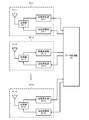
- FIG. 1 is a diagram schematically showing a configuration of a communication system according to an embodiment of the present invention.
- FIG. 2 is a diagram illustrating a configuration example of a communication device that can apply space division multiple access and multiplex a plurality of users.
- FIG. 3 is a diagram illustrating a configuration example of a communication device that does not apply space division multiple access and conforms to a conventional standard such as IEEE802.11a.
- FIG. 4 is a diagram showing a communication sequence example for learning the weight of the adaptive array antenna based on the training signal.
- FIG. 5 is a diagram showing a format example of a training request frame that can be used in the communication sequence shown in FIG.
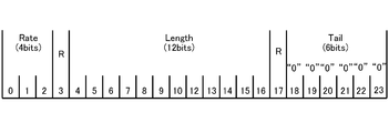
- FIG. 6 shows the data structure of the L-SIG field.
- FIG. 1 is a diagram schematically showing a configuration of a communication system according to an embodiment of the present invention.
- FIG. 2 is a diagram illustrating a configuration example of a communication device that can apply space division multiple access and multiplex a plurality of users.
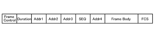
- FIG. 7 is a diagram showing a format example of the payload portion (DATA) in the training request frame shown in FIG.
- FIG. 8 is a diagram showing a format example of a training frame that can be used in the communication sequence shown in FIG.
- FIG. 9A is a diagram showing another format example of a training frame that can be used in the communication sequence shown in FIG.
- FIG. 9B is a diagram showing still another example format of the training frame that can be used in the communication sequence shown in FIG.
- FIG. 10 is a diagram showing a format example of a training frame that can be used in the communication sequence shown in FIG.
- FIG. 11A is a diagram for describing an example of a method for multiplexing a known sequence for learning in a payload portion having backward compatibility.
- FIG. 11A is a diagram for describing an example of a method for multiplexing a known sequence for learning in a payload portion having backward compatibility.
- FIG. 11B is a diagram for explaining an example of a method for multiplexing a known sequence for learning in a payload portion having backward compatibility.
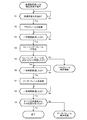
- FIG. 12 is a flowchart showing a processing procedure for the communication apparatus shown in FIG. 2 to operate as an access point (STA0) in the communication sequence shown in FIG.
- FIG. 13 is a flowchart showing a processing procedure for the communication apparatus shown in FIG. 2 or 3 to operate as a terminal station (any one of STA1 to STA3) in the communication sequence shown in FIG.
- FIG. 1 schematically shows a configuration of a communication system according to an embodiment of the present invention.
- the communication system according to the present embodiment conforms to, for example, IEEE 802.11, and uses the RTS / CTS handshake (described above) in combination with the CSMA / CA control procedure.
- the illustrated communication system includes a communication station STA0 that operates as an access point (AP) and a plurality of communication stations STA1, STA2, and STA3 that operate as terminal stations (client devices).
- Each of the communication stations STA1, STA2, and STA3 accommodates the communication station STA0 within its communication range, and can directly communicate with the STA0 (in other words, each of the communication stations STA1, STA2, and STA3 serves as an access point) Of STA0 and configure BSS (Basic Service Set).
- BSS Basic Service Set
- the communication stations STA1, STA2, and STA3 as terminal stations do not need to exist within the communication range of each other, and direct communication between the terminal stations is not described below.
- STA0 as an access point is composed of a communication device having a plurality of antennas and performing space division multiple access using an adaptive array antenna, and multiplexes frame communication by assigning radio resources on the space axis to a plurality of users.
- STA0 is a communication device that complies with a new standard such as IEEE802.11ac, and multiplexes two or more frames with different destination communication stations on the same time axis, or two or more communication stations have the same time.
- One-to-many frame communication is performed by separating, for each transmission source, a frame addressed to the own station that has been multiplexed and transmitted on the axis.
- STA0 can increase the number of terminal stations capable of spatial multiplexing by installing more antennas.
- STA0 not only performs one-to-many frame communication with each communication station STA1, STA2, and STA3 by applying space division multiple access, but also has a one-to-one frame with each communication station STA1, STA2, and STA3. Communication may be performed.
- the communication stations STA1, STA2, and STA3 as terminal stations are composed of communication devices that are equipped with a plurality of antennas and perform space division multiple access using an adaptive array antenna, but perform user separation only at the time of reception, and users at the time of transmission Since separation, that is, multiplexing of transmission frames is not performed, it is not necessary to equip the number of antennas as many as the access points.
- at least a part (not shown in FIG. 1) of the terminal stations placed under the STA0 as an access point may be a communication device compliant with a conventional standard such as IEEE802.11a.
- the communication system shown in FIG. 1 is a communication environment in which the new standard communication devices are mixed with conventional communication devices.
- the communication station STA0 needs to fully consider backward compatibility with conventional standards when operating space division multiple access as an access point.
- FIG. 2 shows an example of the configuration of a communication apparatus that can multiplex a plurality of users by applying space division multiple access.
- the communication station STA0 operating as an access point and the communication stations STA1 to STA3 operating as terminal stations corresponding to some of the space division multiple access are configured as shown in FIG. And perform communication operation in accordance with the new standard.
- the illustrated communication apparatus includes N transmission / reception branches 20-1, 20-2,..., 20-N having antenna elements 21-1, 21-2,. 1, 20-2,..., 20-N, and is composed of a data processing unit 25 that processes transmission / reception data (where N is an integer of 2 or more).
- the plurality of antenna elements 21-1, 21-2,..., 21-N can function as adaptive array antennas by applying appropriate adaptive array antenna weights.
- the communication station STA0 as an access point performs space division multiple access using an adaptive array antenna. However, by having many antenna elements, it is possible to improve the number of terminal stations that can be accommodated by multiple access.
- each antenna element 21-1, 21-2 In each transmitting / receiving branch 20-1, 20-2,..., 20-N, each antenna element 21-1, 21-2,.
- the data processing unit 25 When the data processing unit 25 generates transmission data in response to a transmission request from an upper layer application, the data processing unit 25 distributes the transmission data to each of the transmission / reception branches 20-1, 20-2,.
- the data processing unit 25 In the case of STA0 in which the communication device operates as an access point, the data processing unit 25 generates transmission data addressed to a plurality of users, that is, the communication stations STA1, STA2, and STA3 in response to a transmission request from an upper layer application. .., 20-N after multiplying the transmission weight of the adaptive array antenna for each transmission / reception branch and spatially separating them.
- “space separation” at the time of transmission here means only user separation in which space separation is performed for each user who transmits frames simultaneously.
- Each of the transmission processing units 23-1, 23-2,..., 23-N performs predetermined signal processing such as encoding and modulation on the digital baseband transmission signal supplied from the data processing unit 25. D / A conversion is performed, further up-conversion to an RF (Radio Frequency) signal, and power amplification.
- the transmission RF signal is supplied to the antenna elements 21-1, 21-2,..., 21-N via the duplexers 22-1, 22-2,. .
- each of the reception processing units 24-1, 24-2,..., 24-N the RF reception signals from the antenna elements 21-1, 21-2,. 2,..., 22-N, low-noise amplification, down-conversion to analog baseband signal, D / A conversion, and further predetermined signal such as predetermined decoding and demodulation Apply processing.
- the data processing unit 25 spatially separates the digital reception signals input from the reception processing units 24-1, 24-2,..., 24-N by multiplying the reception weights of the adaptive array antennas respectively.
- the transmission data from each user that is, from each of the communication stations STA1, STA2, and STA3 is reproduced, it is passed to the upper layer application.
- the “spatial separation” at the time of reception mentioned here includes both user separation for spatial separation for each user who transmits frames simultaneously and channel separation for separating spatially multiplexed MIMO channels into a plurality of original streams. Including meaning.
- the data processing unit 25 performs media access control (Media Access Control: MAC) implemented in the communication system shown in FIG. 1 when performing frame transmission / reception in each of the transmission / reception branches 20-1, 20-2,. ) Process of each layer of the communication protocol in the method.
- the data processing unit 25 uses the plurality of antenna elements 21-1, 21-2,..., 21-N in order to make the adaptive array antenna function.
- 20-N the transmission weight of the adaptive array antenna is applied to the transmitted signal, and the received signal from each transmission / reception branch 20-1, 20-2,.
- the transmission processing units 23-1, 23-2,..., 23-N and the reception processing units 24-1, 24-2,..., 24-N are controlled so as to apply the reception weight of the array antenna.
- the data processing unit 25 learns the weight of the adaptive array antenna prior to space division multiple access with each of the communication stations STA1, STA2, and STA3. For example, adaptive array antenna weight learning is performed using a predetermined adaptive algorithm such as RLS (Recursive Last Square) on a training signal (described later) consisting of a known sequence received from each communication partner STA1 to STA3. be able to.
- RLS Recursive Last Square
- the communication stations STA1, STA2, and STA3 as terminal stations have a plurality of antennas and perform space division multiple access using an adaptive array antenna, but perform user separation only at the time of reception, and user separation at the time of transmission, that is, a transmission frame Therefore, it is not necessary to equip as many antennas as the access point.
- FIG. 3 shows a configuration example of a communication device that does not apply space division multiple access and conforms to a conventional standard such as IEEE802.11a.
- a conventional standard such as IEEE802.11a.
- some of the terminal stations placed under the STA0 as an access point have the configuration shown in FIG. 3 and perform a communication operation only in accordance with the conventional standard ( (Not shown in FIG. 1).
- the 3 includes a transmission / reception branch 30 including an antenna element 31 and a data processing unit 35 connected to the transmission / reception branch 30 to process transmission / reception data.
- the antenna element 31 is connected to the transmission processing unit 33 and the reception processing unit 34 via the duplexer 32.
- the data processing unit 35 generates transmission data in response to a transmission request from an upper layer application and outputs the transmission data to the transmission / reception branch 30.
- the transmission processing unit 33 performs predetermined signal processing such as encoding and modulation on the digital baseband transmission signal, performs D / A conversion, further up-converts the signal into an RF signal, and amplifies the power. Then, the transmission RF signal is supplied to the antenna element 31 via the duplexer 32 and emitted into the air.
- the reception processing unit 34 performs low-noise amplification and then down-converts to an analog baseband signal, and then performs D / A conversion. Further, predetermined signal processing such as predetermined decoding and demodulation is performed.
- the data processing unit 35 reproduces the original transmission data from the digital reception signal input from the reception processing unit 34 and passes it to the upper layer application.
- the STA0 as an access point is adapted to apply adaptive array antenna weights to a plurality of antenna elements 21-1, 21-2,.
- Directivity for each of the communication stations STA1 to STA3 can be formed by functioning as an array antenna.
- radio resources on the space axis can be separated for each user, and a plurality of frames addressed to the communication stations STA1 to STA3 can be multiplexed and transmitted simultaneously.
- STA0 functions as an adaptive array antenna, so that each frame simultaneously transmitted from each communication station STA1 to STA3 can be separated and processed for each user on the space axis.
- the STA0 can learn the weight of the adaptive array antenna by acquiring a transfer function from a training signal that is a known sequence received from each of the communication stations STA1 to STA3.
- STA0 can directly learn the weight of the adaptive array antenna using a predetermined adaptive algorithm such as RLS (Recursive Last Square) for training signals received from each of a plurality of communication partners. .
- RLS Recursive Last Square
- STA0 that learns the weight of the adaptive array antenna needs to send a training signal to each of the communication stations STA1 to STA3. Also, in a communication environment where communication devices conforming only to the conventional standard are mixed, interference caused by the communication device conforming only to the conventional standard is caused in the same manner as a normal frame exchange sequence must be performed while avoiding carrier collision. The training signal must be transmitted while avoiding it. That is, STA0 needs to learn the weight of the adaptive array antenna while maintaining backward compatibility with the conventional standard.
- FIG. 4 shows an example of a communication sequence for learning the weight of the adaptive array antenna based on the training signal.
- the communication station STA0 that performs learning transmits a training request (TRQ: Training ReQuest) frame that requests transmission of a training signal
- TRQ Training ReQuest
- each peripheral station STA1 to STA3 that has received the TRQ frame uses a known sequence for learning.
- a training frame that includes Note that the communication station STA4 in FIG. 4 is not included in FIG. 1, but is a communication station that conforms only to the conventional standard, and is a hidden terminal that exists within at least one communication range among the communication stations STA0 to STA3. Suppose there is.
- STA0 as an access point performs physical carrier sense in advance to confirm that the medium is clear, and further performs backoff, and then transmits a TRQ frame.
- the weight of the adaptive array antenna has not yet been learned (that is, a plurality of antenna elements 21-1, 21-2,..., 21-N are not functioning as an adaptive array antenna).
- the TRQ frame includes a field conforming to IEEE 802.11, which is the conventional standard, and until a series of signal transmission / reception sequences are completed with respect to a communication station (hidden terminal) that is not the destination of the TRQ frame (in the illustrated example, transmission of ACK is performed). Duration information (described later) requesting to set the counter value of the NAV corresponding to the period of (until completion) is described. The format of the TRQ frame will be described later.
- the STA 4 When the STA 4 according to the conventional standard receives the TRQ frame not including its own station, the STA 4 sets the NAV counter value based on the duration information described in the frame and refrains from the transmission operation.
- the TRQ frame transmitted from STA0 reaches each communication station STA1 to STA3.
- each of the communication stations STA1 to STA3 receives the TRQ frame in which the address of its own station is described in the destination address, and then, after a predetermined frame interval SIFS (Short Inter Frame Space) has elapsed, the adaptive array Return the training frames (Training1, Training2, and Training3) each including a known sequence that can be used for antenna learning.
- SIFS Short Inter Frame Space
- the training frame in order to learn the weight of the adaptive array antenna while maintaining backward compatibility with the conventional standard, the training frame includes the first half field according to IEEE 802.11, which is the conventional standard, and the conventional standard. Consists of the latter field containing a known sequence for training that is not backward compatible.
- the training / The spoofing described shall be applied so as to misidentify that the frame continues.
- the format of the training frame will be described later.
- each of the communication stations STA1 to STA3 transmits a training frame at the same time.
- a method of transmitting each training frame in time division is also conceivable.
- time-division transmission a period until transmission of all training frames is completed with an increase in the number of communication stations that return training frames (that is, learning must be performed) (that is, transmissions to neighboring stations). (Waiting period) becomes long, leading to a decrease in throughput of the entire system and an increase in overhead.
- a peripheral station hidden terminal
- training frames are transmitted simultaneously.
- STA0 waits to receive a training frame returned from each destination station STA1 to STA3 of the TRQ frame. Since STA0 does not learn the adaptive array antenna at the time of receiving the training frame, it is necessary to simultaneously receive a plurality of training frames using any one of the antenna elements. Here, when the following three conditions are satisfied, STA0 can receive the first half of the backward compatible field portion of the simultaneously transmitted training fields while avoiding the collision.
- the OFDM modulation method is used.
- the oscillators of the communication stations STA1, STA2, and STA3 operate so as to correct the frequency error with the oscillator used in STA0.
- (3) The description contents of the corresponding fields of the training frame transmitted by each communication station STA1, STA2, and STA3 are all the same.
- condition (1) is strong against multipath fading.
- condition (2) can be satisfied when each of the communication stations STA1, STA2, and STA3 performs frequency correction when receiving the TRQ frame from the STA0. By performing the frequency correction, it is ensured that the delay time at which the training frames transmitted simultaneously from the respective communication stations STA1, STA2, and STA3 arrive at STA0 falls within the guard interval.
- condition (3) if the corresponding fields of each communication station STA1, STA2, and STA3 have the same description, they can be handled in the same way as a normal delayed wave, and one antenna element can be handled. Can be received simultaneously.
- STA0 has a plurality of antenna elements 21-1, 21-2,. Receive using -N.
- STA0 can spatially separate the sequences.
- the known sequence naturally becomes longer because it is necessary to distinguish each communication station.
- STA0 learns the weight of the adaptive array antenna using a predetermined adaptive algorithm such as the RLS algorithm based on each known sequence. Thereafter, the plurality of antenna elements 21-1, 21-2,..., 21-N of STA0 function as an adaptive array antenna, and STA0 can perform space division multiple access.
- a predetermined adaptive algorithm such as the RLS algorithm
- the STA 4 when the STA 4 that conforms only to the conventional standard receives any of the training frames (Training 1, Training 2, and Training 3) that do not include the own station as a destination, the STA 4 until the transmission end time of the subsequent ACK frame by spoofing Misunderstanding that the training frame will continue and refrain from sending.
- STA0 receives data frames (Fragment0) addressed to each of the communication stations STA1, STA2, and STA3 after a predetermined frame interval SIFS has elapsed since the completion of reception of the training frames from the communication stations STA1, STA2, and STA3. -1, Fragment 0-2, Fragment 0-3) are transmitted. By using the learned adaptive array antenna weight, STA0 can spatially multiplex these multiple data frames and transmit them simultaneously.
- the plurality of antenna elements 21-1, 21-2,..., 21-N of STA0 have already functioned as adaptive antennas, and a plurality of simultaneously received ACK frames (ACK1, ACK2, ACK3) are provided for each user. Can be separated. For example, by describing the addresses of the communication stations STA1, STA2, and STA3 as the respective transmitter addresses in each ACK frame, STA0 can identify the transmission source of each received ACK frame. If a known sequence for training is also included in the ACK frame, STA0 changes the weight of the learned adaptive array antenna to the environment change based on the known sequence included in each received ACK frame. It can be made to follow adaptively.
- the STA 4 When the STA 4 according to the conventional standard receives any of the data frames (Fragment 0-1, Fragment 0-2, Fragment 0-3) not addressed to the local station, the STA 4 performs NAV based on the duration information described in the frame. Set a counter value for and refrain from sending. In addition, when the STA 4 according to the conventional standard receives any of the ACK frames (ACK1, ACK2, ACK3) not addressed to itself, it sets the NAV counter value based on the duration information described in the frame. And refrain from the transmission operation.
- the STA 4 receives any of the data frames (Fragment 0-1, Fragment 0-2, Fragment 0-3) not addressed to the local station, the STA 4 performs NAV based on the duration information described in the frame. Set a counter value for and refrain from sending.
- the STA 4 according to the conventional standard receives any of the ACK frames (ACK1, ACK2, ACK3) not addressed to itself, it sets the NAV counter value based on the duration information described in
- the STA0 that performs space division multiple access can appropriately learn the weight of the adaptive array antenna, and after further learning, By sharing a resource among a plurality of users and multiplexing and transmitting a plurality of data frames addressed to the plurality of users, it is possible to improve the throughput of one-to-many, that is, the entire plurality of users.
- FIG. 5 shows a format example of a training request frame that can be used in the communication sequence shown in FIG.
- the illustrated training request frame includes a header portion and a payload portion (DATA).
- DATA payload portion
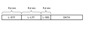
- the header part of the training request frame is an L-STF (Legacy Short Training Field) consisting of known OFDM symbols for frame discovery, and an L-LTF (Legacy Long Training Field) consisting of known training symbols for synchronization acquisition and equalization.
- L-SIG Legacy SIGNAL Field
- the training frame can be configured in a format compliant with IEEE 802.11, which is a conventional standard, in both the header part and the payload part, and a peripheral station compliant with only the conventional standard can also be received.
- FIG. 6 shows the data structure of the L-SIG field in the training request frame shown in FIG.
- the format of the L-SIG field is a definition common to other frame formats described later.
- Information indicating the transmission rate used for transmission of the payload portion is described in the Rate field, and information indicating the data length of the payload portion is described in the Length field.
- the communication station that has received the frame calculates the data length divided by the information specified by Rate and Length obtained by decoding the L-SIG, thereby calculating the time until the end of the frame. Can be sought.
- FIG. 7 shows a format example of the payload portion (DATA) in the training request frame shown in FIG.
- a frame control field and a duration field are defined in common. Thereafter, a plurality of address fields Addr1 to 4, a sequence field (SEQ), a frame body that is net information provided to an upper layer, and an FCS (Frame Check Sequence) that is a checksum follow.
- SEQ sequence field
- FCS Frae Check Sequence
- the frame control has a further subdivided format, and describes, for example, various information such as the type of the frame, the version of the protocol, the presence / absence of retransmission, and data path information.
- Duration is provided to specify the time.
- Each communication station that has received the frame grasps the time to refrain from the communication operation based on the time described in this duration when the address of the own station is not described in the address fields Addr1 to 4. be able to.
- a counter value called NAV Network Allocation Vector
- the counter value indicates, for example, the transmission completion time of the subsequent ACK frame.
- the plurality of address fields Addr1 to 4 are used to specify the source and destination communication stations.
- each address of each of the communication stations STA1 to STA3 which is a training request destination, is described in the address field.
- the frame check sequence is a 32-bit CRC (Cyclic Redundancy Check). For example, the destination station of the frame recalculates the frame check sequence and checks whether or not they match. If it does not match the sent frame check sequence, the frame is discarded as being destroyed, and only the correct MAC (Media Access Control) frame is recognized and processed. become.
- CRC Cyclic Redundancy Check
- FIG. 8 shows a format example of a training frame that can be used in the communication sequence shown in FIG.
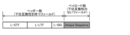
- the training frame shown in the figure is composed of a header portion composed of a format compliant with IEEE 802.11, which is a conventional standard (ie, having backward compatibility), and a payload portion that is not backward compatible with the conventional standard.
- the header part is composed of L-STF, L-LTF, and L-SIG in the same manner as the training request frame described above.
- a plurality of communication stations STA1 to STA3 transmit training frames simultaneously.
- STA0 which is the training request source, is in a state where learning of the adaptive array antenna is not performed, and needs to be received simultaneously using one antenna element.
- the header of the training frame transmitted by each of the communication stations STA1 to STA3 Since the description contents of the parts are the same, STA0 can receive simultaneously using one antenna element.
- the data structure of the L-SIG field in the training frame is as shown in FIG. Normally, the time until the end of the frame can be obtained by calculating the data length divided by the transmission rate based on the information specified by Rate and Length.
- the Length and Rate fields in the header part are not information indicating the original frame length and transmission rate, but the period in which the data length / transmission rate should be NAV (the subsequent ACK frame The information disguised to be (transmission completion time) is stored. Therefore, when the peripheral station STA4 of the conventional standard receives the frame, the peripheral station STA4 stops the transmission operation for an appropriate period based on the decoding result of the header part (L-SIG) having backward compatibility. It is not necessary to interfere with the communication sequence shown in FIG. It should be noted that the fact that the payload part consisting of Unique Sequence follows the header part may be described in the L-SIG.
- a known sequence for learning is written.
- STA0 spatially assigns each sequence from the training frames received simultaneously. Can be separated (as described above).
- FIG. 9A shows another format example of the training frame that can be used in the communication sequence shown in FIG.
- the illustrated training frame consists of a header part and a payload part.
- the header portion is composed of L-STF, L-LTF, and L-SIG as in the above-described training request frame, but conforms to the conventional IEEE802.11 standard and has backward compatibility.
- the payload part includes a DATA field having backward compatibility and a Unique Sequence field having no backward compatibility.
- the illustrated training frame can also be expressed as a configuration in which a UNIQUE SEQUENCE field for learning is added to the rear of a data frame defined by IEEE 802.11.
- the data structure of the L-SIG field is as shown in FIG. 6 and includes a Length field describing information indicating the data length of the payload portion.
- the data length of the payload part is the combined length of the DATA field and the Unique Sequence field.
- the frame control and the duration are defined in common at the head, as in the format example shown in FIG.
- a NAV counter value corresponding to the transmission completion time of the subsequent ACK frame is set.
- the DATA field has backward compatibility, and the peripheral station conforming to the conventional standard can grasp the time for which the communication operation should be refrained based on the duration described in the DATA field. it can.
- the peripheral station conforming to the conventional standard can grasp the time for which the communication operation should be refrained based on the duration described in the DATA field. it can.
- the STA0 that is the training request source is in a state where learning of the adaptive array antenna is not performed, and in order to simultaneously receive the header part and the DATA field having backward compatibility using one antenna element, these Must be the same description (same as above).
- the description content of the header part of the training frame transmitted by each of the communication stations STA1 to STA3 is the same as in the format example shown in FIG.
- the frame control and duration defined in common in the head of the DATA field have the same description content in the training frames transmitted by the respective communication stations STA1 to STA3.
- an address field is defined in the DATA frame, it is necessary to make arrangements in advance so that the same address information is described between the communication stations STA1 to STA3.
- the peripheral station STA4 does not need to decode the UNIQUE SEQUENCE field having no backward compatibility as a payload portion.
- the received power is expected to decrease after the end of the payload portion, as shown in FIG. 9A, if the DATA field and the Unique Sequence field are seamlessly connected, they should be reduced originally. Since the received power continues as it is, depending on the implementation of the peripheral station STA4, there is a possibility that the L-SIG information is recognized as having an error, the entire packet is discarded, and the NAV is invalidated.
- a training frame format in which a non-transmission section of a predetermined length is provided between the DATA field and the Unique Sequence field can be cited.
- the peripheral station STA4 of the conventional standard recognizes that the L-SIG information is correct and does not have to discard the received packet. Set the NAV. Therefore, the transmission source of the training frame can transmit the Unique Sequence field without any problem after the non-transmission period from the DATA field.
- the section length of the non-transmission section may be a short section such as SIFS (Short Inter Frame Space). Further, it may be described that the UNIQUE SEQUENCE field follows in the DATA field.
- SIFS Short Inter Frame Space
- FIG. 10 shows still another format example of the training frame that can be used in the communication sequence shown in FIG.
- the illustrated training frame includes a header portion and a payload portion (DATA).
- DATA payload portion
- the header portion conforms to IEEE 802.11, which is a conventional standard composed of L-STF, L-LTF, and L-SIG, and has backward compatibility.
- the payload portion can be configured in a format compliant with IEEE 802.11, which is a conventional standard, and for example, a data structure similar to that shown in FIG. 7 can be adopted.
- STA0 which is a training request source, is in a state where learning of an adaptive array antenna is not performed, and a header part and a payload part having backward compatibility must be received simultaneously using one antenna element.
- Each communication station STA1 to STA3 makes the description content of the header part and the payload part the same, so that STA0 can receive simultaneously using one antenna element.
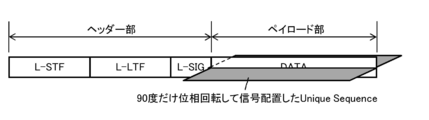
- a learning known sequence is multiplexed and transmitted in a payload portion having backward compatibility. It can be said that the illustrated training frame is obtained by multiplexing the training signal on the payload portion of the data frame defined by IEEE 802.11.
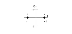
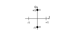
- FIG. 11 illustrates a multiplexing method in the case of applying BPSK (Binary Phase Shift Keying) as a digital modulation method. That is, with respect to the original payload portion, as shown in FIG. 11A, the conventional signal arrangement is performed. On the other hand, as shown in FIG. 11B, the known sequence for learning is transmitted with a signal arrangement whose phase is rotated by 90 degrees.
- BPSK Binary Phase Shift Keying
- the NAV information is transmitted to the peripheral station STA4 while being carried on the original payload portion, and learning is performed to the destination station STA0. It is possible to transmit a training signal for use.
- STA0 is multiplexed from the payload portion of the training frame received simultaneously.
- Each sequence can be spatially separated.
- FIG. 12 shows a processing procedure for the communication apparatus shown in FIG. 2 to operate as an access point (STA0) in the communication sequence shown in FIG. 4 in the form of a flowchart.
- the access point starts the processing procedure shown in FIG. 12 in response to a data transmission request or reception request from an upper layer application.
- step S2 When the access point performs a physical carrier sense in advance to confirm that the medium is clear, and further performs a backoff, the local station is ready for transmission (Yes in step S1).
- a training request (TRQ) frame (see FIG. 5) is transmitted to one or more terminal stations (STA1 to STA3) that want to multiplex and transmit data (step S2).
- the access point completes transmission of the TRQ frame, and when a predetermined frame interval SIFS has elapsed (Yes in step S3), the training frame (FIG. 8 to FIG. 8) returned from each training request destination (STA1 to STA3). It waits for reception (see FIG. 10) (step S4).
- the access point when the access point cannot receive the training frame from any of the training request destinations (STA1 to STA3) (No in step S5), the access point shifts to a TRQ frame retransmission process. However, the details of the frame retransmission processing procedure will not be described.
- the access point can receive a training frame from any one or more training request destinations (STA1 to STA3) (Yes in step S5), the learning included in each received training frame.
- the adaptive array antenna weights are learned using the known sequence for.
- the access point passes the predetermined frame interval SIFS (Yes in step S6) to the terminal station that has received the training frame.
- a data frame is transmitted (step S7).
- the access point can spatially multiplex and simultaneously transmit data frames addressed to a plurality of terminal stations by using the learned weights of the adaptive array antenna.
- the terminal station that could not receive the training frame is not trained, and since it is unknown whether it exists in the communicable range in the first place, transmission of the data frame is withheld.
- the access point waits for reception of an ACK frame returned from the transmission destination of each data frame (Ste S9).
- the access point When the access point has received ACK frames from all data frame transmission destinations (Yes in step S9), it can successfully terminate the processing routine.
- the access point fails to receive an ACK frame from any data frame transmission destination (No in step S9) or receives a NACK frame, it recognizes that transmission / reception of the data frame has failed.
- the data frame is retransmitted. However, the details of the frame retransmission processing procedure will not be described.
- FIG. 13 shows a processing procedure for the communication apparatus shown in FIG. 2 or 3 to operate as a terminal station (any one of STA1 to STA3) in the communication sequence shown in FIG. 4 in the form of a flowchart. Yes.
- each terminal station starts the processing procedure shown in FIG. 13 in response to receiving a TRQ frame from the access point.
- each terminal station performs frequency error correction using, for example, the L-LTF in the header portion of the received TRQ frame, and that each clock error is guaranteed to be within the guard interval. .
- the terminal station returns a training frame to the access point after a predetermined frame interval SIFS has elapsed after completing the reception of the TRQ frame from the access point (Yes in step S11) (step S12).
- the terminal station performs frequency error correction using the received TRQ frame. Therefore, when there are multiple terminal stations that send back training frames, it is guaranteed that the arrival time at the access point will be within the guard interval, so the access point must receive simultaneously using one antenna element. Can do.
- step S14 the terminal station waits for reception of a data frame transmitted from the access point when a predetermined frame interval SIFS has elapsed (Yes in step S13) (step S14).
- the terminal station may return a NACK prompting the access point to retransmit the data frame.
- step S15 when the terminal station is able to receive a data frame from the access point (Yes in step S15), the access is performed after a predetermined frame interval SIFS has elapsed after completion of reception of the data frame (Yes in step S16). An ACK frame is returned to the point (step S17), and the processing routine can be completed successfully.
- the STA0 as an access point and the STA1 to STA3 as terminal stations execute the processing procedures shown in FIGS. 12 and 13, respectively, thereby realizing the communication sequence shown in FIG. Then, STA0 performing space division multiple access can preferably learn the weight of the adaptive array antenna.
- STA0 shares the radio resources on the spatial axis with a plurality of users, multiplexes and transmits a plurality of data frames addressed to the plurality of users, One-to-many, that is, throughput for a plurality of users as a whole can be improved.
- the embodiment applied to a new wireless LAN standard such as IEEE802.11ac aiming at realizing ultra-high throughput of 1 Gbps has been mainly described, but the gist of the present invention is not limited to this. Absent.
- the present invention can be similarly applied to other wireless LAN systems in which wireless resources on the space axis are shared by a plurality of users and various wireless systems other than the LAN.
Landscapes
- Engineering & Computer Science (AREA)
- Computer Networks & Wireless Communication (AREA)
- Signal Processing (AREA)
- Mobile Radio Communication Systems (AREA)
- Radio Transmission System (AREA)
Abstract
従来規格との下位互換性を保ちながら、空間分割多元接続に必要となるアダプティブ・アレイ・アンテナの重みの学習を行なう。 学習のためのTRQフレーム及びトレーニング・フレームを交換する際には、これらのフレームに偽装を施して、従来規格に従う周辺局STA4との衝突を好適に回避する。また、STA0は、アダプティブ・アレイ・アンテナの重みを学習した後は、空間軸上の無線リソースを複数のユーザーで共有して複数ユーザー宛ての複数のデータ・フレームを多重化して送信することで、1対多すなわち複数ユーザー全体でのスループットを向上させる。
Description
本発明は、空間軸上の無線リソースを複数のユーザーで共有する空間分割多元接続(Space Division Multuple Access:SDMA)を適用する通信装置及び通信方法、コンピューター・プログラム、並びに通信システムに係り、特に、空間分割多元接続を適用しない従来規格との下位互換性を保ちながら、空間分割多元接続を適用した新規規格に則って通信動作を行なう通信装置及び通信方法、コンピューター・プログラム、並びに通信システムに関する。
無線通信は、旧来の有線通信における配線作業の負担を解消し、さらには移動体通信を実現する技術として利用に供されている。例えば、無線LAN(Local Area Network)に関する標準的な規格として、IEEE(The Institute of Electrical and Electronics Engineers)802.11を挙げることができる。IEEE802.11a/gは既に広く普及している。
IEEE802.11を始めして多くの無線LANシステムでは、CSMA/CA(Carrier Sense MultipleAccess with Collision Avoidance:搬送波感知多重アクセス)などのキャリアセンスに基づくアクセス制御手順を採り入れて、各通信局はランダム・チャネル・アクセス時におけるキャリアの衝突を回避するようにしている。すなわち、送信要求が発生した通信局は、まず所定のフレーム間隔DIFS(Distributed Inter Frame Space)だけメディア状態を監視し、この間に送信信号が存在しなければ、ランダム・バックオフを行ない、さらにこの間にも送信信号が存在しない場合に、送信権を得てフレームを送信することができる。また、通信局は、ACKなどの例外的に緊急度の高いフレームを送信する際には、より短いフレーム間隔SIFS(Short Inter Frame Space)の後にフレームを送信することが許される。これにより、緊急度の高いフレームは、通常のCSMAの手順に従って送信されるフレームよりも先に送信することが可能となる。
また、無線通信においては、通信局が互いに直接通信できない領域が存在するという隠れ端末問題が生じることが知られている。隠れ端末同士ではネゴシエーションを行なうことができないため、送信動作が衝突する可能性がある。隠れ端末問題を解決する方法論として、「仮想キャリアセンス」を挙げることができる。具体的には、通信局は、自局宛てでない受信フレーム中にメディアを予約するためのDuration(持続時間)情報が記載されている場合には、Duration情報に応じた期間はメディアが使用されているものと予想すなわち仮想キャリアセンスして、送信停止期間(NAV:Network Allocation Vector)を設定する。
仮想キャリアセンスを利用した信号送受信シーケンスの代表例として、RTS/CTSハンドシェイクを挙げることができる。データ送信元の通信局が送信要求フレーム(RTS:Request To Send)を送信し、データ送信先の通信局から確認通知フレーム(CTS:Clear To Send)を受信したことに応答してデータ送信を開始する。そして、隠れ端末は、自局宛てでないRTS又はCTSのうち少なくとも一方のフレームを受信すると、受信フレーム中に記載されているDuration情報に基づいて送信停止期間を設定して、衝突を回避する。CSMA/CA制御手順にRTS/CTSハンドシェイクを併用することにより、過負荷状態における衝突のオーバーヘッドの削減が図られることがある。
また、IEEE802.11a/gの規格では、2.4GHz帯あるいは5GHz帯周波数において、直交周波数分割多重(Orthogonal Frequency Division Multiplexing:OFDM)を利用して、最大(物理層データレート)で54Mbpsの通信速度を達成する変調方式をサポートしている。拡張規格であるIEEE802.11nではMIMO(Multi-Input Multi-Output)通信方式を採用してさらなる高ビットレートを実現している。ここで、MIMOとは、送信機側と受信機側の双方において複数のアンテナ素子を備え、空間多重したストリームを実現する通信方式である(周知)。
IEEE802.11nは、IEEE802.11a/gとの下位互換性が保たれている。例えば、IEEE802.11nのフレーム・フォーマットでは、ヘッダー部が下位互換性を保証したシグナル情報(L-SIG)フィールドを偽装(spoof)する方法が採用されている。具体的には、シグナル情報(L-SIG)内には偽装したフレーム長情報と伝送レート情報を記載して、IEEE802.11a/gに準拠するレガシー通信端末に対して、下位互換性のないフレーム交換シーケンスが完了するまでの間はフレームが続くように認識させ、送信動作を待機させることによって衝突を回避する。他方、IEEE802.11nに準拠する通信端末に対しては、ヘッダー部の下位互換性を保証しないシグナル情報(HT-SIG)フィールドの一部の信号配置を切り替えることによってL-SIGが偽装されていることを示すようになっている。したがって、IEEE802.11nに準拠する高速通信端末は、HT-SIGの復号結果を基に正しいDuratoin情報を取得して、適切な仮想キャリアセンスを行なうことができる(例えば、特許文献1を参照のこと)。
IEEE802.11nによって100Mbps超の高スループット(High Throughput:HT)を達成できるものの、伝送コンテンツの情報量の増大に伴い、さらなる高速化が求められている。例えば、MIMO通信機のアンテナ本数を増やして空間多重するストリーム数が増加することによって、下位互換性を保ちながら、1対1の通信におけるスループットを向上させることができる。
将来は、通信におけるユーザー当たりのスループットに加え、複数ユーザー全体でのスループットを向上させることが要求されている。例えば、IEEE802.11ac作業部会では、6GHz以下の周波数帯を使い、データ伝送速度が1Gbpsを超える無線LAN規格の策定を目指しているが、その実現には、マルチユーザーMIMO(MU-MIMO)若しくはSDMA(Space Division Multuple Access)のように、空間軸上の無線リソースを複数のユーザーで共有する空間分割多元接続方式が有力である。
現在のところ、空間分割多元接続は、PHS(Personal Handyphone System)やLTE(Long Term Evolution)などの時分割多元接続(Time Division Multiple Access:TDMA)をベースにした次世代携帯電話系システムの基盤技術の一つとして検討されている。また、無線LAN分野では、上記のように1対多の通信が注目されつつあるが、適用例はほとんどない。これは、フレーム通信において複数のユーザーを効率よく多重化することが難しいことにも依拠すると思料される。
また、新規の無線LAN規格で空間分割多元接続の運用を開始する際には、当該新規規格の通信機が従来規格の通信機と混在する通信環境下で動作する必要があることから、従来規格との下位互換性を十分に考慮する必要がある。
例えば、新規規格に準拠する通信局が空間分割多元接続を適用して複数の通信相手に対して同時にフレームを送信する際、当該フレームの送信元並びに送信先の通信局の少なくとも一方を通信範囲に収容する隠れ端末は、新規規格に準拠しておらず多重化信号を復号できないとしても、一連のフレーム交換シーケンスが終了するまでの期間にわたって送信動作を差し控えて、伝送信号の衝突を回避しなければならない。
従来からのIEEE802.11規格では、CSMA/CA、RTS/CTSといったキャリアセンスのメカニズムが導入されている。したがって、IEEE802.11acなどの新規規格においては、キャリアセンスと空間分割多元接続を好適に組み合わせる必要がある。
例えば、従来からのIEEE802.11規格とは下位互換性を保つフレーム・フォーマットからなるRTS、CTS、ACKフレームを用いて、従来からのIEEE802.11規格におけるキャリアセンスとアダプティブ・アレイ・アンテナによる空間分割多元接続という2つの技術を組み合わせた通信システムについて提案がなされている(例えば、特許文献2を参照のこと)。
また、通信局は、複数本のアンテナ素子がアダプティブ・アレイ・アンテナとして機能することによって空間分割多元接続を行なうことが可能となるが、そのためにはアダプティブ・アレイ・アンテナの重みの学習を事前に行なう必要がある。例えば、通信局は、複数の通信相手の各々から受信したトレーニング信号から伝達関数を取得することによってアダプティブ・アレイ・アンテナの重みを学習することができる。あるいは、トレーニング信号に対してRLS(Recursive Least Square)などの所定の適応アルゴリズムを用いて、アダプティブ・アレイ・アンテナの重みの学習を直接行なうことができる(例えば、特許文献2を参照のこと)。
いずれの方法にせよ、アダプティブ・アレイ・アンテナの重みの学習を行なう通信局は、通信相手の各々にトレーニング信号を送ってもらう必要がある。また、従来規格にのみ従う通信装置が混在する通信環境下では、キャリアの衝突を回避しながら通常のフレーム交換シーケンスを実施しなければならないのと同様に、従来規格にのみ従う通信装置による干渉を回避しながら、トレーニング信号を伝送させなければならない。すなわち、従来規格との下位互換性を保ちながらアダプティブ・アレイ・アンテナの重みの学習を行なう必要がある。
本発明の目的は、空間軸上の無線リソースを複数のユーザーで共有する空間分割多元接続を適用して好適に通信動作を行なうことができる、優れた通信装置及び通信方法、コンピューター・プログラム、並びに通信システムを提供することにある。
本発明のさらなる目的は、空間分割多元接続を適用しない従来規格との下位互換性を保ちながら、空間分割多元接続を適用した新規規格に則って好適に通信動作を行なうことができる、優れた通信装置及び通信方法、コンピューター・プログラム、並びに通信システムを提供することにある。
本発明のさらなる目的は、従来規格との下位互換性を保ちながら、空間分割多元接続に必要となるアダプティブ・アレイ・アンテナの重みの学習を行なうことができる、優れた通信装置及び通信方法、コンピューター・プログラム、並びに通信システムを提供することにある。
本願は、上記課題を参酌してなされたものであり、請求項1に記載の発明は、
アンテナ素子と、
前記アンテナ素子を用いて無線信号の送受信処理を行なう通信部と、
前記通信部において送受信するデータを処理するデータ処理部と、
を備え、
前記データ処理部は、下位互換性のある第1の通信規格に従って記載された第1のフィールドと、複数のアンテナ素子を備えた通信相手がアダプティブ・アレイ・アンテナの重みを学習するためのトレーニング信号を含んだ第2のフィールドからなる、トレーニング・フレームを生成して、前記通信部から送信させる、
通信装置である。
アンテナ素子と、
前記アンテナ素子を用いて無線信号の送受信処理を行なう通信部と、
前記通信部において送受信するデータを処理するデータ処理部と、
を備え、
前記データ処理部は、下位互換性のある第1の通信規格に従って記載された第1のフィールドと、複数のアンテナ素子を備えた通信相手がアダプティブ・アレイ・アンテナの重みを学習するためのトレーニング信号を含んだ第2のフィールドからなる、トレーニング・フレームを生成して、前記通信部から送信させる、
通信装置である。
本願の請求項2に記載の発明によれば、請求項1の記載の通信装置から送信されるトレーニング信号は、当該通信装置に割り当てられた固有の既知シーケンスからなる。
本願の請求項3に記載の発明によれば、前記第1の通信規格はIEEE802.11に相当し、前記トレーニング・フレームの前記第1のフィールドはL-SIGフィールドまでを含み、前記第2のフィールドはL-SIGフィールドの後方に付加されたトレーニング信号からなる。また、請求項1の記載の通信装置のデータ処理部は、L-SIGフィールド内のLength及びRateに、データ長÷伝送レートが前記通信相手との通信シーケンス単位の終端までの長さを表す、偽装した情報を記載するように構成されている。
本願の請求項4に記載の発明によれば、請求項3の記載の通信装置のデータ処理部は、前記第1のフィールドの後に前記第2のフィールドが続くことをL-SIGフィールド内に記載するように構成されている。
本願の請求項5に記載の発明によれば、前記トレーニング・フレームの前記第1のフィールドは前記第1の通信規格はIEEE802.11で規定されるデータ・フレームに相当し、前記第2のフィールドは、前記データ・フレームの後方に付加されたトレーニング信号からなる。また、請求項1に記載の通信装置のデータ処理部は、L-SIGフィールド内のLengthを、前記データ・フレームの終端までを前記トレーニング・フレームのペイロード部のデータ長として表す情報に偽装する。
本願の請求項6に記載の発明によれば、請求項1に記載の通信装置のデータ処理部は、請求項5に記載のトレーニング・フレームの前記第1のフィールドの終端から前記第2のフィールドの先頭までを離間する無送信区間を設けるようになっている。
本願の請求項7に記載の発明によれば、請求項4に記載の通信装置のデータ処理部は、L-SIGフィールド内のLengthに、前記第1のフィールドの終端までを前記トレーニング・フレームのペイロード部のデータ長として表す情報に偽装するように構成されている。
本願の請求項8に記載の発明によれば、前記トレーニング・フレームの前記第1のフィールドは前記第1の通信規格はIEEE802.11で規定されるデータ・フレームに相当し、前記第2のフィールドは、前記データ・フレームのペイロード部に多重されたトレーニング信号からなる。
また、本願の請求項9に記載の発明は、複数のアンテナ素子を備えた通信相手に対してトレーニング・フレームを送信する通信方法であって、
前記トレーニング・フレームのうち下位互換性のある第1の通信規格に従って記載された第1のフィールドを送信するステップと、
前記トレーニング・フレームのうち前記通信相手がアダプティブ・アレイ・アンテナの重みを学習するためのトレーニング信号を含んだ第2のフィールドを送信するステップと、
を有する通信方法である。
前記トレーニング・フレームのうち下位互換性のある第1の通信規格に従って記載された第1のフィールドを送信するステップと、
前記トレーニング・フレームのうち前記通信相手がアダプティブ・アレイ・アンテナの重みを学習するためのトレーニング信号を含んだ第2のフィールドを送信するステップと、
を有する通信方法である。
また、本願の請求項10に記載の発明は、複数のアンテナ素子を備えた通信相手に対してトレーニング・フレームを送信するための処理をコンピューター上で実行するようにコンピューター可読形式で記述されたコンピューター・プログラムであって、前記コンピューターを、
下位互換性のある第1の通信規格に従って記載された第1のフィールドと、複数のアンテナ素子を備えた通信相手がアダプティブ・アレイ・アンテナの重みを学習するためのトレーニング信号を含んだ第2のフィールドからなる、トレーニング・フレームを生成するデータ処理部、
として機能させるためのコンピューター・プログラムである。
下位互換性のある第1の通信規格に従って記載された第1のフィールドと、複数のアンテナ素子を備えた通信相手がアダプティブ・アレイ・アンテナの重みを学習するためのトレーニング信号を含んだ第2のフィールドからなる、トレーニング・フレームを生成するデータ処理部、
として機能させるためのコンピューター・プログラムである。
本願の請求項10に係るコンピューター・プログラムは、コンピューター上で所定の処理を実現するようにコンピューター可読形式で記述されたコンピューター・プログラムを定義したものである。換言すれば、本願の請求項10に係るコンピューター・プログラムをコンピューターにインストールすることによって、コンピューター上では協働的作用が発揮され、本願の請求項1に係る通信装置と同様の作用効果を得ることができる。
また、本願の請求項11に記載の発明は、複数のアンテナ素子と、前記複数のアンテナ素子を用いて無線信号の送受信処理を行なう通信部と、前記通信部において送受信するデータを処理するデータ処理部を備えた第1の通信装置と、
前記第1の通信装置に対して、前記複数のアンテナ素子についてのアダプティブ・アレイ・アンテナの重みを学習するためのトレーニング信号を含んだトレーニング・フレームを同時送信する、複数の第2の通信装置と、
で構成され、
前記複数の第2の通信装置はそれぞれ、位互換性のある第1の通信規格に従って記載された第1のフィールドと、複数のアンテナ素子を備えた通信相手がアダプティブ・アレイ・アンテナの重みを学習するためのトレーニング信号を含んだ第2のフィールドからなる、トレーニング・フレームを送信する、
通信システムである。
前記第1の通信装置に対して、前記複数のアンテナ素子についてのアダプティブ・アレイ・アンテナの重みを学習するためのトレーニング信号を含んだトレーニング・フレームを同時送信する、複数の第2の通信装置と、
で構成され、
前記複数の第2の通信装置はそれぞれ、位互換性のある第1の通信規格に従って記載された第1のフィールドと、複数のアンテナ素子を備えた通信相手がアダプティブ・アレイ・アンテナの重みを学習するためのトレーニング信号を含んだ第2のフィールドからなる、トレーニング・フレームを送信する、
通信システムである。
但し、ここで言う「システム」とは、複数の装置(又は特定の機能を実現する機能モジュール)が論理的に集合した物のことを言い、各装置や機能モジュールが単一の筐体内にあるか否かは特に問わない。
本発明によれば、空間軸上の無線リソースを複数のユーザーで共有する空間分割多元接続を適用して好適に通信動作を行なうことができる、優れた通信装置及び通信方法、コンピューター・プログラム、並びに通信システムを提供することができる。
また、本発明によれば、空間分割多元接続を適用しない従来規格との下位互換性を保ちながら、空間分割多元接続を適用した新規規格に則って好適に通信動作を行なうことができる、優れた通信装置及び通信方法、コンピューター・プログラム、並びに通信システムを提供することができる。
また、本発明によれば、従来規格との下位互換性を保ちながら、空間分割多元接続に必要となるアダプティブ・アレイ・アンテナの重みの学習を行なうことができる、優れた通信装置及び通信方法、コンピューター・プログラム、並びに通信システムを提供することができる。
本願の請求項1、9乃至11に記載の発明によれば、トレーニング信号を供給する通信装置は、下位規格に相当する第1の通信規格に準拠した周辺局が混在する通信環境下に適用することができ、このような周辺局を第1のフィールドに記載された情報に基づいて通信動作を行なわせることで、下位互換性を保ちながら通信相手に対してトレーニング信号を供給することができる。
本願の請求項2に記載の発明によれば、トレーニング信号は通信装置毎に割り当てられた固有の既知シーケンスからなるので、複数の通信装置からトレーニング信号を同時受信する通信相手は、複数のトレーニング信号を空間的にユーザー毎に分離することができる。
本願の請求項3、4に記載の発明によれば、トレーニング・フレームは、IEEE802.11と下位互換性を持つヘッダー部を備え、且つ、ヘッダー部内のL-SIGフィールド内では、本来のフレーム長及び伝送レートを表す情報ではなく、データ長÷伝送レートがNAVを立てるべき期間(後続のACKフレームの送信完了時刻)となるように偽装されたLength並びにRate情報が格納される。従来のIEEE802.11に準拠する周辺局は、トレーニング・フレーム中の下位互換性のない第2のフィールドを復号することができなくても、当該通信装置が通信相手と行なう通信シーケンス単位にわたり送信動作を控えるようになる。したがって、通信装置は、下位互換性を保ちながら通信相手に対してトレーニング信号を供給することができる。
本願の請求項5に記載の発明によれば、トレーニング・フレームは、IEEE802.11のデータ・フレームの後方にトレーニング信号が付加された構造を備えている。従来のIEEE802.11に準拠する周辺局は、トレーニング・フレームのうちIEEE802.11のペイロード部の先頭に定義されたデュレーションを参照してNAVのカウンター値を設定することによって、当該通信装置が通信相手と行なう通信シーケンス単位にわたり送信動作を控えるようになる。したがって、通信装置は、下位互換性を保ちながら通信相手に対してトレーニング信号を供給することができる。また、L-SIGフィールド内のLengthを、前記データ・フレームの終端までを前記トレーニング・フレームのペイロード部のデータ長として表す情報に偽装するので、従来のIEEE802.11に準拠する周辺局は、トレーニング・フレーム中の下位互換性のない第2のフィールドを復号する必要がなくなる。
本願の請求項6に記載の発明によれば、データ・フレームに相当する第1のフィールドの終端と、トレーニング信号からなる第2のフィールドの間に所定長の無送信区間が設けられているので、従来のIEEE802.11に準拠する周辺局は、データ・フレームを受信後に一旦は期待通りに受信電力が低下することから、L-SIGの情報が正しいものと認識し、受信パケットを破棄しないで済む。
本願の請求項7に記載の発明によれば、周辺局は、デュレーションに記載されているNAV情報が有効であることを認識しながら、当該通信装置が通信相手と行なう通信シーケンス単位にわたり送信動作を控えるようになる。したがって、本発明に係る通信装置は、下位互換性を保ちながら通信相手に対してトレーニング信号を供給することができる。
本願の請求項8に記載の発明によれば、IEEE802.11のデータ・フレームに相当する構造を備えている。従来のIEEE802.11に準拠する周辺局は、トレーニング・フレームのうちIEEE802.11のペイロード部の先頭に定義されたデュレーションを参照してNAVのカウンター値を設定することによって、当該通信装置が通信相手と行なう通信シーケンス単位にわたり送信動作を控えることができる。したがって、本発明に係る通信装置は、下位互換性を保ちながら通信相手に対してトレーニング信号を供給することができる。
本発明のさらに他の目的、特徴や利点は、後述する本発明の実施形態や添付する図面に基づくより詳細な説明によって明らかになるであろう。
以下、図面を参照しながら本発明の実施形態について詳細に説明する。
図1には、本発明の一実施形態に係る通信システムの構成を模式的に示している。本実施形態に係る通信システムは、例えばIEEE802.11に準拠しており、CSMA/CA制御手順にRTS/CTSハンドシェイク(前述)を併用するものとする。
図示の通信システムは、アクセスポイント(AP)として動作する通信局STA0と、端末局(クライアント・デバイス)として動作する複数の通信局STA1、STA2、STA3で構成される。各通信局STA1、STA2、STA3はそれぞれの通信範囲内に通信局STA0を収容し、それぞれSTA0とは直接通信を行なうことができる(言い換えれば、各通信局STA1、STA2、STA3は、アクセスポイントとしてのSTA0の配下に置かれ、BSS(Basic Service Set)を構成する)。但し、端末局としての各通信局STA1、STA2、STA3が互いの通信範囲内に存在する必要はなく、以下では端末局間での直接通信については言及しない。
ここで、アクセスポイントとしてのSTA0は、複数のアンテナを備えアダプティブ・アレイ・アンテナによる空間分割多元接続を行なう通信装置からなり、空間軸上の無線リソースを複数ユーザーに割り当てて、フレーム通信を多重化する。すなわち、STA0は、IEEE802.11acなどの新規規格に準拠する通信装置であり、宛て先通信局が異なる2以上のフレームを同一の時間軸上で多重化したり、2以上の通信局が同一の時間軸上で多重化送信した自局宛てのフレームを送信元毎に分離したりして、1対多のフレーム通信を行なう。STA0は、より多くのアンテナを装備することで、空間多重が可能な端末局の台数を増大することができる。勿論、STA0は、空間分割多元接続を適用して各通信局STA1、STA2、STA3と1対多のフレーム通信を行なうだけでなく、各通信局STA1、STA2、STA3と個別に1対1でフレーム通信を行なってもよい。
他方、端末局としての通信局STA1、STA2、STA3は、複数のアンテナを備えアダプティブ・アレイ・アンテナによる空間分割多元接続を行なう通信装置からなるが、受信時のみユーザー分離を行ない、送信時のユーザー分離すなわち送信フレームの多重化を行なわないので、アクセスポイントほどのアンテナ本数を装備する必要はない。なお、アクセスポイントとしてのSTA0の配下に置かれる端末局のうち少なくとも一部(図1中には図示しない)は、IEEE802.11aなどの従来規格に準拠した通信装置であってもよい。言い換えれば、図1に示す通信システムは、該新規規格の通信機が従来規格の通信機と混在する通信環境である。
したがって、通信局STA0は、アクセスポイントとして空間分割多元接続を運用する際に、従来規格との下位互換性を十分に考慮する必要がある。
図2には、空間分割多元接続を適用し、複数ユーザーの多重化を行なうことができる通信装置の構成例を示している。図1に示した通信システムにおいて、アクセスポイントとして動作する通信局STA0や、端末局として動作する通信局STA1~STA3のうち一部の空間分割多元接続に対応したものは、図2に示した構成を備え、新規規格に則って通信動作を行なうものとする。
図示の通信装置は、それぞれアンテナ素子21-1、21-2、…、21-Nを備えたN本の送受信ブランチ20-1、20-2、…、20-Nと、各送受信ブランチ20-1、20-2、…、20-Nと接続して、送受信データの処理を行なうデータ処理部25で構成される(但し、Nは2以上の整数)。これら複数のアンテナ素子21-1、21-2、…、21-Nは、適当なアダプティブ・アレイ・アンテナの重みをかけることによって、アダプティブ・アレイ・アンテナとして機能することができる。アクセスポイントとしての通信局STA0は、アダプティブ・アレイ・アンテナによる空間分割多元接続を行なうが、多くのアンテナ素子を持つことで、多元接続により収容可能な端末局台数を向上することが可能である。
各送受信ブランチ20-1、20-2、…、20-N内では、各アンテナ素子21-1、21-2、…、21-Nが、共用器22-1、22-2、…、22-Nを介して、送信処理部23-1、23-2、…、23-N並びに受信処理部24-1、24-2、…、24-Nに接続されている。
データ処理部25は、上位層アプリケーションからの送信要求に応じて送信データを生成すると、各送受信ブランチ20-1、20-2、…、20-Nに振り分ける。また、通信装置がアクセスポイントとして動作するSTA0の場合、データ処理部25は、上位層アプリケーションからの送信要求に応じて、複数のユーザーすなわち各通信局STA1、STA2、STA3宛ての送信データを生成すると、送受信ブランチ毎のアダプティブ・アレイ・アンテナの送信重みを乗算して空間分離してから、各送受信ブランチ20-1、20-2、…、20-Nに振り分ける。但し、ここで言う送信時の「空間分離」は、フレームを同時送信するユーザー毎に空間分離するユーザー分離のみを意味するものとする。
各送信処理部23-1、23-2、…、23-Nは、データ処理部25から供給されたディジタル・ベースバンド送信信号に対し、符号化、変調などの所定の信号処理を施した後にD/A変換して、さらにRF(Radio Frequency)信号へのアップコンバートし、電力増幅する。そして、かかる送信RF信号は、共用器22-1、22-2、…、22-Nを介してアンテナ素子21-1、21-2、…、21-Nに供給され、空中に放出される。
一方、各受信処理部24-1、24-2、…、24-Nでは、アンテナ素子21-1、21-2、…、21-NからのRF受信信号が共用器22-1、22-2、…、22-Nを介して供給されると、低雑音増幅してからアナログ・ベースバンド信号へダウンコンバートし、その後にD/A変換し、さらに所定の復号、復調などの所定の信号処理を施す。
データ処理部25は、各受信処理部24-1、24-2、…、24-Nから入力されるディジタル受信信号に対してアダプティブ・アレイ・アンテナの受信重みをそれぞれ乗算して空間分離し、ユーザー毎すなわち通信局STA1、STA2、STA3の各々からの送信データを再現すると、上位層アプリケーションに渡す。但し、ここで言う受信時の「空間分離」には、フレームを同時送信するユーザー毎に空間分離するユーザー分離と、空間多重されたMIMOチャネルを元の複数のストリームに分離するチャネル分離の双方の意味を含むものとする。
データ処理部25は、各送受信ブランチ20-1、20-2、…、20-Nでフレーム送受信を行なう際に、図1に示す通信システムで実装されるメディア・アクセス制御(Media Access Control:MAC)方式における通信プロトコルの各層の処理を実行する。ここで、データ処理部25は、複数のアンテナ素子21-1、21-2、…、21-Nをアダプティブ・アレイ・アンテナを機能させるために、各送受信ブランチ20-1、20-2、…、20-Nに振り分けた送信信号に対してアダプティブ・アレイ・アンテナの送信重みをかけ、また、各送受信ブランチ20-1、20-2、…、20-Nからの受信信号に対してアダプティブ・アレイ・アンテナの受信重みをかけるよう、各送信処理部23-1、23-2、…、23-N並びに各受信処理部24-1、24-2、…、24-Nを制御する。また、データ処理部25は、各通信局STA1、STA2、STA3との空間分割多元接続に先立ち、アダプティブ・アレイ・アンテナの重みを学習しておく。例えば、各通信相手STA1~STA3から受信した既知シーケンスからなるトレーニング信号(後述)に対してRLS(Recursive Least Square)などの所定の適応アルゴリズムを用いて、アダプティブ・アレイ・アンテナの重みの学習を行なうことができる。
なお、端末局としての通信局STA1、STA2、STA3は、複数のアンテナを備えアダプティブ・アレイ・アンテナによる空間分割多元接続を行なうが、受信時のみユーザー分離を行ない、送信時のユーザー分離すなわち送信フレームの多重化を行なわないので、アクセスポイントほどのアンテナ本数を装備する必要はない。
また、図3には、空間分割多元接続を適用せず、IEEE802.11aなどの従来規格に準拠した通信装置の構成例を示している。図1に示した通信システムにおいて、アクセスポイントとしてのSTA0の配下に置かれる端末局の中には、図3に示した構成を備え、従来規格に則ってのみ通信動作を行なうものも存在する(図1中には図示しない)。
図3に示す通信装置は、アンテナ素子31を備えた送受信ブランチ30と、この送受信ブランチ30と接続して、送受信データの処理を行なうデータ処理部35で構成される。また、送受信ブランチ30内では、アンテナ素子31が、共用器32を介して、送信処理部33並びに受信処理部34に接続されている。
データ処理部35は、上位層アプリケーションからの送信要求に応じて送信データを生成して、送受信ブランチ30に出力する。送信処理部33は、ディジタル・ベースバンド送信信号に対し、符号化、変調などの所定の信号処理を施した後、D/A変換し、さらにRF信号へのアップコンバートし、電力増幅する。そして、かかる送信RF信号は、共用器32を介してアンテナ素子31に供給され、空中に放出される。
一方、受信処理部34では、アンテナ素子31からのRF受信信号が共用器32を介して供給されると、低雑音増幅してからアナログ・ベースバンド信号へダウンコンバートし、その後にD/A変換して、さらに所定の復号、復調などの所定の信号処理を施す。データ処理部35は、受信処理部34から入力されるディジタル受信信号から元の送信データを再現して、上位層アプリケーションに渡す。
図1に示した通信システムにおいて、アクセスポイントとしてのSTA0は、複数本のアンテナ素子21-1、21-2、…、21-Nに対してアダプティブ・アレイ・アンテナの重みをかけることによってアダプティブ・アレイ・アンテナとして機能させて、各通信局STA1~STA3に対する指向性を形成することができる。この結果、空間軸上の無線リソースをユーザー毎に分離して、各通信局STA1~STA3宛ての複数のフレームを多重化して同時送信することができる。また、STA0は、アダプティブ・アレイ・アンテナとして機能することによって、各通信局STA1~STA3から同時送信された各フレームを空間軸上でユーザー毎に分離して受信処理することができる。
ここで、複数本のアンテナ素子21-1、21-2、…、21-Nがアダプティブ・アレイ・アンテナとして機能するためには、アダプティブ・アレイ・アンテナの重みの学習を事前に行なう必要がある。例えば、STA0は、各通信局STA1~STA3からそれぞれ受信した既知シーケンスからなるトレーニング信号から伝達関数を取得することによってアダプティブ・アレイ・アンテナの重みを学習することができる。あるいは、STA0は、複数の通信相手の各々から受信したトレーニング信号に対してRLS(Recursive Least Square)などの所定の適応アルゴリズムを用いて、アダプティブ・アレイ・アンテナの重みの学習を直接行なうことができる。
いずれの方法にせよ、アダプティブ・アレイ・アンテナの重みの学習を行なうSTA0は、各通信局STA1~STA3にトレーニング信号を送ってもらう必要がある。また、従来規格にのみ従う通信装置が混在する通信環境下では、キャリアの衝突を回避しながら通常のフレーム交換シーケンスを実施しなければならないのと同様に、従来規格にのみ従う通信装置による干渉を回避しながら、トレーニング信号を伝送させなければならない。すなわち、STA0は、従来規格との下位互換性を保ちながらアダプティブ・アレイ・アンテナの重みの学習を行なう必要がある。
図4には、トレーニング信号に基づいてアダプティブ・アレイ・アンテナの重みを学習するための通信シーケンス例を示している。図示の例では、学習を行なう通信局STA0がトレーニング信号の送信を要求するトレーニング要求(TRQ:Training ReQuest)フレームを送信し、TRQフレームを受信した各周辺局STA1~STA3がそれぞれ学習に用いる既知シーケンスを含んだトレーニング・フレームを返信するようになっている。なお、図4中の通信局STA4は、図1には含まれないが、従来規格にのみ準拠した通信局であり、通信局STA0~STA3のうち少なくとも1つの通信範囲内に存在する隠れ端末であるとする。
アクセスポイントとしてのSTA0は、事前に物理キャリアセンスを行なってメディアがクリアであることを確認し、さらにバックオフを行なった後に、TRQフレームを送信する。この時点ではまだアダプティブ・アレイ・アンテナの重みを学習していない(すなわち、複数本のアンテナ素子21-1、21-2、…、21-Nがアダプティブ・アレイ・アンテナとして機能していない)ことから、無指向性でTRQフレームを送信する。
TRQフレームは、従来規格であるIEEE802.11に従うフィールドを含み、TRQフレームの宛て先でない通信局(隠れ端末)に対し、一連の信号送受信シーケンスが終了するまで(図示の例では、ACKの送信が完了するまで)の期間に相当するNAVのカウンター値を設定することを要求するデュレーション情報(後述)が記載されている。TRQフレームのフォーマットについては後述に譲る。
従来規格に従うSTA4は、自局を宛て先に含まない上記TRQフレームを受信した場合には、当該フレーム内に記載されたデュレーション情報に基づいてNAVのカウンター値を設定して、送信動作を控える。
また、図1に示した通信局配置では、STA0から送信されたTRQフレームは各通信局STA1~STA3に届く。これに対し、各通信局STA1~STA3は、宛て先アドレスに自局のアドレスが記載されたTRQフレームを受信してから所定のフレーム間隔SIFS(Short Inter Frame Space)が経過した後に、アダプティブ・アレイ・アンテナの学習に用いることができる既知シーケンスを含んだトレーニング・フレーム(Training1、Training2、Training3)をそれぞれ返信する。
本実施形態では、従来規格との下位互換性を保ちながらアダプティブ・アレイ・アンテナの重みの学習を行なうために、トレーニング・フレームは、従来規格であるIEEE802.11に従う前半のフィールドと、従来規格とは下位互換性のない、トレーニング用の既知シーケンスを含んだ後半のフィールドからなる。前半の従来規格に従うフィールド内では、従来規格に準拠した周辺局が一連の信号送受信シーケンスが終了するまでの期間にわたり送信動作を控えさせるために、後にACKの送信が完了する時点までは当該トレーニング・フレームが続くと誤認させるよう、記載の偽装(spoofing)を施すものとする。但し、トレーニング・フレームのフォーマットについては後述に譲る。
また、図4に示す例では、各通信局STA1~STA3は、トレーニング・フレームを同時送信するようになっている。
ここで、各トレーニング・フレームを時分割で送信する方法も考えられる。しかしながら、時分割送信すると、トレーニング・フレームを返信する(すなわち、学習しなければならない)通信局の台数の増加とともにすべてのトレーニング・フレームの送信が終了するまでの期間(すなわち、周辺局にとっての送信待機期間)が長くなってしまうため、システム全体のスループットの低下やオーバーヘッドの増大を招来する。また、時間軸上で後方に送信されるトレーニング・フレームしか受信できない周辺局(隠れ端末)は、トレーニング・フレームが届く前にNAVのカウンター値が消滅して、送信動作を開始してしまう可能性があり、キャリアの衝突を回避できなくなる。これらの理由により、本実施形態では、トレーニング・フレームを同時送信する。
一方、STA0は、TRQフレームを送信完了した後、TRQフレームの各宛て先局STA1~STA3からそれぞれ返信されるトレーニング・フレームを受信待機する。STA0は、トレーニング・フレームを受信する時点では、アダプティブ・アレイ・アンテナの学習を行なっていないことから、いずれか1つのアンテナ素子を用いて同時に複数のトレーニング・フレームを受信する必要がある。ここで、以下の3つの条件を満たす場合には、STA0は、同時送信されるトレーニング・フィールドのうち前半の下位互換性を持つフィールド部分を、衝突を回避して受信することが可能となる。
(1)OFDM変調方式を用いていること。
(2)各通信局STA1、STA2、STA3の発振器がSTA0で用いる発振器との周波数誤差を補正するように動作すること。
(3)各通信局STA1、STA2、STA3が送信するトレーニング・フレームの該当フィールドの記載内容がすべて同一であること。
(2)各通信局STA1、STA2、STA3の発振器がSTA0で用いる発振器との周波数誤差を補正するように動作すること。
(3)各通信局STA1、STA2、STA3が送信するトレーニング・フレームの該当フィールドの記載内容がすべて同一であること。
条件(1)のOFDM変調方式は、マルチパス・フェージングに強いことが知られている。また、条件(2)は、各通信局STA1、STA2、STA3が、STA0からのTRQフレーム受信時に周波数補正を実施することで満足することができる。周波数補正を実施することにより、各通信局STA1、STA2、STA3から同時送信されるトレーニング・フレームがSTA0に到達する遅延時刻は、ガード・インターバル内に収まることが保証される。そして、条件(3)で挙げるように、各通信局STA1、STA2、STA3の該当フィールドが同一の記載内容であれば、これらを通常の遅延波と同様に扱うことができ、1つのアンテナ素子を用いて同時に受信することが可能になる。
また、トレーニング・フレームのうち、従来規格とは下位互換性のない、トレーニング用の既知シーケンスを含んだ後半のフィールドについては、STA0は、複数のアンテナ素子21-1、21-2、…、21-Nを用いて受信する。あらかじめ各通信局STA1、STA2、STA3にそれぞれ固有のコード・シーケンスをトレーニング用の既知シーケンスとして割り当てておくことにより、STA0は、各々のシーケンスを空間的に分離することができる。但し、空間分割によって多元接続する通信局の台数が増大すると、各々を区別する必要から、既知シーケンスは自ずと長くなる。
そして、STA0は、各既知シーケンスに基づいて、RLSアルゴリズムなどの所定の適応アルゴリズムを用いてアダプティブ・アレイ・アンテナの重みを学習する。以降、STA0が持つ複数本のアンテナ素子21-1、21-2、…、21-Nはアダプティブ・アレイ・アンテナとして機能し、STA0は空間分割多元接続を行なうことが可能になる。
他方、従来規格にのみ従うSTA4は、自局を宛て先に含まない上記トレーニング・フレーム(Training1、Training2、Training3)のいずれかを受信した場合には、spoofingにより後続のACKフレームの送信終了時刻までトレーニング・フレームが継続するものと誤認して、送信動作を控える。
STA0は、各通信局STA1、STA2、STA3からのトレーニング・フレームを受信完了してから所定のフレーム間隔SIFSが経過した後に、各通信局STA1、STA2、STA3の各々に宛てたデータ・フレーム(Fragment0-1、Fragment0-2、Fragment0-3)をそれぞれ送信する。STA0は、上記の学習したアダプティブ・アレイ・アンテナの重みを利用することで、これら複数のデータ・フレームを空間分割多重して同時送信することができる。
これに対し、各通信局STA1、STA2、STA3は、それぞれ自局宛てのデータ・フレーム(Fragment0-1、Fragment0-2、Fragment0-3)を受信完了すると、所定のフレーム間隔SIFSが経過した後に、ACKフレーム(ACK1、ACK2、ACK3)を同時に返信する。
STA0の複数本のアンテナ素子21-1、21-2、…、21-Nは既にアダプティブ・アンテナとして機能しており、同時受信した複数のACKフレーム(ACK1、ACK2、ACK3)をユーザー毎に空間分離することができる。例えば、各ACKフレームに各々のトランスミッタ・アドレスとして通信局STA1、STA2、STA3のアドレスがそれぞれ記載しておくことにより、STA0は、受信した各ACKフレームの送信元を特定することができる。また、ACKフレームにもトレーニング用の既知シーケンスを含ませておくと、STA0は、受信した各ACKフレームに含まれる既知シーケンスに基づいて、学習済みのアダプティブ・アレイ・アンテナの重みを、環境変化に適応的に追従させることができる。
従来規格に従うSTA4は、自局宛てでない上記データ・フレーム(Fragment0-1、Fragment0-2、Fragment0-3)のいずれかを受信した場合には、そのフレーム内に記載されたデュレーション情報に基づいてNAVのカウンター値を設定して、送信動作を控える。また、従来規格に従うSTA4は、自局宛てでない上記ACKフレーム(ACK1、ACK2、ACK3)のいずれかを受信した場合には、そのフレーム内に記載されたデュレーション情報に基づいてNAVのカウンター値を設定して、送信動作を控える。
図4に例示した通信シーケンスからも分かるように、空間分割多元接続を行なうSTA0は、アダプティブ・アレイ・アンテナの重みを好適に学習することができるとともに、さらに学習した後は、空間軸上の無線リソースを複数のユーザーで共有して複数ユーザー宛ての複数のデータ・フレームを多重化して送信することで、1対多すなわち複数ユーザー全体でのスループットを向上させることができる。
図5には、図4に示した通信シーケンスで使用することができる、トレーニング要求フレームのフォーマット例を示している。図示のトレーニング要求フレームは、ヘッダー部と、ペイロード部(DATA)からなる。
トレーニング要求フレームのヘッダー部は、フレーム発見用の既知OFDMシンボルからなるL-STF(Legacy Short Training Field)と、同期獲得並びに等化用の既知トレーニング・シンボルからなるL-LTF(Legacy Long Training Field)と、伝送レートやデータ長などのシグナル情報を記載したL-SIG(Legacy SIGNAL Field)で構成され、これに続いてペイロード部(Data)が送信される。トレーニング・フレームは、ヘッダー部及びペイロード部ともに、従来規格であるIEEE802.11に準拠したフォーマットで構成することができ、従来規格にのみ準拠する周辺局も受信することができる。
図6には、図5に示したトレーニング要求フレーム中のL-SIGフィールドのデータ構造を示している。なお、L-SIGフィールドのフォーマットは、後述するその他のフレーム・フォーマットと共通の定義である。Rateフィールドには、ペイロード部の伝送に用いられる伝送レートを表す情報が記載され、Lengthフィールドには、ペイロード部のデータ長を表す情報が記載される。当該フレームを受信した通信局は、L-SIGを復号して得られたRate及びLengthで特定される情報を基に、データ長÷伝送レートを計算することで、当該フレームの終端までの時間を求めることができる。
図7には、図5に示したトレーニング要求フレーム中のペイロード部(DATA)のフォーマット例を示している。
ペイロード部の先頭には、フレーム・コントロール(Frame Control)フィールドとデュレーション(Duration)フィールドが共通に定義されている。その後、複数のアドレス・フィールドAddr1~4と、シーケンス・フィールド(SEQ)と、上位レイヤに提供する正味の情報であるFrame Bodyと、チェックサムであるFCS(Frame Check Sequence)が続く。
フレーム・コントロールは、さらに細分化されたフォーマットを有するものであり、例えば、当該フレームの種別やプロトコルのバージョン、再送の有無、データの経路情報といった各種情報が記述される。
デュレーションは、時間の指定を行なうために設けられる。当該フレームを受信した各通信局は、アドレス・フィールドAddr1~4に自局のアドレスが記述されていない場合には、このデュレーションに記述された時間に基づいて、通信動作を控えるべき時間を把握することができる。具体的には、このデュレーションには、NAV(Network Allocation Vector)と称されるカウンター値が設定される。カウンター値は、例えば後続のACKフレームの送信完了時刻を指すものとする。
複数のアドレス・フィールドAddr1~4は、送信元や宛先通信局他の特定を行なうために用いられる。図1に示す通信シーケンス例の場合、アドレス・フィールドには、トレーニング要求先である各通信局STA1~STA3の各アドレスが記載されることになる。
フレーム・チェック・シーケンス(FCS)は、32ビットのCRC(Cyclic Redundancy Check)である。例えば当該フレームの宛て先局は、このフレーム・チェック・シーケンスを再計算して、両者が一致するか否かをチェックする。そして、送られてきたフレーム・チェック・シーケンスと一致しなかった場合には、そのフレームは破壊されたものとして廃棄することにより、正しいMAC(Media Access Control)フレームのみを認識し、処理を行なうことになる。
図8には、図4に示した通信シーケンスで使用することができる、トレーニング・フレームのフォーマット例を示している。
図示のトレーニング・フレームは、従来規格であるIEEE802.11に準拠した(すなわち、下位互換性を持つ)フォーマットからなるヘッダー部と、従来規格とは下位互換性のないペイロード部からなる。
ヘッダー部は、上述したトレーニング要求フレームと同様に、L-STF、L-LTF、L-SIGからなる。図4に示した通信シーケンス例では、複数の通信局STA1~STA3がトレーニング・フレームを同時に送信することになる。トレーニング要求元であるSTA0は、アダプティブ・アレイ・アンテナの学習を行なっていない状態であり、1つのアンテナ素子を用いて同時に受信する必要がある。OFDM変調方式を用いていることと、トレーニング・フレームの送信元である各通信局STA1~STA3が周波数誤差を補正していることに加え、各通信局STA1~STA3が送信するトレーニング・フレームのヘッダー部の記載内容が同一であることから、STA0は、1つのアンテナ素子を用いて同時に受信することが可能である。
また、トレーニング・フレーム中のL-SIGフィールドのデータ構造は、図6に示した通りである。通常は、Rate及びLengthで特定される情報を基に、データ長÷伝送レートを計算することで、当該フレームの終端までの時間を求めることができる。これに対し、spoofing技術では、ヘッダー部内のLength、Rateの各フィールドには、本来のフレーム長及び伝送レートを表す情報ではなく、データ長÷伝送レートがNAVを立てるべき期間(後続のACKフレームの送信完了時刻)となるように偽装された情報が格納される。したがって、従来規格の周辺局STA4は、当該フレームを受信した際には、下位互換性を持つヘッダー部(L-SIG)の復号結果に基づいて、適切な期間だけ送信動作を停止して、図4に示した通信シーケンスを干渉しないで済む。なお、ヘッダー部の後にUnique Sequenceからなるペイロード部が続くことを、L-SIG内に記載するようにしてもよい。
ペイロード部には、学習用の既知シーケンスが記載される。あらかじめ各通信局STA1、STA2、STA3にそれぞれ固有のコード・シーケンス(Unique Sequence)をトレーニング用の既知シーケンスとして割り当てておくことにより、STA0は、同時受信するトレーニング・フレームから各々のシーケンスを空間的に分離することができる(前述)。
図9Aには、図4に示した通信シーケンスで使用することができる、トレーニング・フレームの他のフォーマット例を示している。
図示のトレーニング・フレームは、ヘッダー部とペイロード部からなる。ヘッダー部は、上述したトレーニング要求フレームと同様に、L-STF、L-LTF、L-SIGからなるが、従来規格であるIEEE802.11に準拠し、下位互換性を持つ。他方、ペイロード部は、下位互換性を持つDATAフィールドと、下位互換性を持たないUnique Sequenceフィールドからなる。図示のトレーニング・フレームは、IEEE802.11で規定するデータ・フレームの後方に、学習のためのUniuqe Sequenceフィールドを付加した構成と表現することもできる。
L-SIGフィールドのデータ構造は、図6に示した通りであり、ペイロード部のデータ長を表す情報を記載するLengthフィールドを含んでいる。ペイロード部のデータ長は、DATAフィールドとUnique Sequenceフィールドを合わせた長さである。但し、従来規格に準拠する周辺局にとっては、下位互換性を持たないUnique Sequenceフィールドを、ペイロード部として復号する必要のない。そこで、Lengthフィールドには、Unique Sequenceフィールドを外した、下位互換性を持つDATAフィールドの終端までをペイロード部のデータ長として偽装した情報が記載される。
DATAフィールドは、図7に示したフォーマット例と同様に、先頭にフレーム・コントロールとデュレーションが共通に定義されている。デュレーションには、後続のACKフレームの送信完了時刻に相当する、NAVのカウンター値が設定される。
図9Aに示したフォーマット例では、DATAフィールドは下位互換性を持ち、従来規格に準拠する周辺局は、DATAフィールド内に記載されたデュレーションに基づいて、通信動作を控えるべき時間を把握することができる。このため、図8に示したフォーマット例とは相違し、L-SIG内のLength及びRateフィールドを、フレーム長÷伝送レートがNAVを立てるべき期間となるように偽装する必要はない。むしろ、周辺局は、デュレーションに記載されているNAV情報が有効であることを認識しなければならない。そこで、上述のように、Lengthフィールドは、Unique Sequenceフィールドを外した、下位互換性を持つDATAフィールドの終端までをペイロード部のデータ長として表す情報に偽装される。
トレーニング要求元であるSTA0は、アダプティブ・アレイ・アンテナの学習を行なっていない状態であり、下位互換性を持つヘッダー部及びDATAフィールドを、1つのアンテナ素子を用いて同時に受信するためには、これらの部分を同一の記載内容にする必要がある(同上)。各通信局STA1~STA3が送信するトレーニング・フレームのヘッダー部の記載内容が同一であることは、図8に示したフォーマット例と同様である。他方、DATAフィールドのうち、先頭で共通に定義されるフレーム・コントロール及びデュレーションは、各通信局STA1~STA3が送信するトレーニング・フレームで同一の記載内容となる。また、DATAフレームにアドレス・フィールドが定義されている場合には、各通信局STA1~STA3の間で、同じアドレス情報を記載するよう、あらかじめ取り決めておく必要がある。
図9Aに示したトレーニング・フレームにおいて、上述したように、L-SIGフィールド内のLengthフィールドを、下位互換性を持つDATAフィールドの終端までをペイロード部のデータ長として表す情報に偽装すると、従来規格の周辺局STA4は、下位互換性を持たないUnique Sequenceフィールドは、ペイロード部として復号する必要がなくなる。ところが、ペイロード部の終端以降は受信電力が低下することが期待されるにも拘らず、図9Aに示したように、DATAフィールドとUnique Sequenceフィールドがシームレスに連結されていると、本来低下すべき受信電力がそのまま継続するため、周辺局STA4の実装次第では、L-SIGの情報に誤りがあったと認識し、パケット全体を破棄し、NAVを無効化してしまう可能性がある。
この問題の解決方法として、図9Bに示すように、DATAフィールドとUnique Sequenceフィールドの間に所定長の無送信区間を設けたトレーニング・フレームのフォーマットを挙げることができる。この場合、DATAフィールドの終端以降で一旦は期待通りに受信電力が低下することから、従来規格の周辺局STA4は、L-SIGの情報が正しいものと認識し、受信パケットを破棄しないで済み、NAVの設定を行なう。したがって、トレーニング・フレームの送信元は、DATAフィールドから無送信区間の後に、問題なくUnique Sequenceフィールドを送信することができる。
なお、無送信区間の区間長は、例えばSIFS(Short Inter Frame Space)などの短い区間でよい。また、DATAフィールド内に、その後にUnique Sequenceフィールドが続くことを記載するようにしてもよい。
図10には、図4に示した通信シーケンスで使用することができる、トレーニング・フレームのさらに他のフォーマット例を示している。図示のトレーニング・フレームは、ヘッダー部と、ペイロード部(DATA)からなる。
ヘッダー部は、上述したトレーニング要求フレームと同様に、L-STF、L-LTF、L-SIGからなる、従来規格であるIEEE802.11に準拠し、下位互換性を持つ。
また、ペイロード部は、従来規格であるIEEE802.11に準拠したフォーマットで構成することができ、例えば図7に示したものと同様のデータ構造を採用することができる。
トレーニング要求元であるSTA0は、アダプティブ・アレイ・アンテナの学習を行なっていない状態であり、下位互換性を持つヘッダー部及びペイロード部を、1つのアンテナ素子を用いて同時に受信しなければならない。各通信局STA1~STA3がヘッダー部及びペイロード部の記載内容を同一にすることで、STA0は、1つのアンテナ素子を用いて同時に受信することが可能になる。
また、図10に示す例では、下位互換性を持つペイロード部に、学習用の既知シーケンスを多重して送信される。図示のトレーニング・フレームは、IEEE802.11で規定するデータ・フレームのペイロード部に、トレーニング信号を多重したものと言うこともできる。
下位互換性を持つペイロード部にトレーニング信号としての既知シーケンスを多重する方法の一例として、本来のペイロード部とは信号点配置が異なるディジタル変調を施す方法が挙げられる。図11には、ディジタル変調方式としてBPSK(Binary Phase Shift Keying:2位相偏移変調)を適用する場合における多重方法を図解している。すなわち、本来のペイロード部については、図11Aに示すように、従来通りの信号配置を行なう。これに対し、学習用の既知シーケンスについては、図11Bに示すように、90度だけ位相回転した信号配置で送信する。このように、本来のペイロード部とトレーニング信号を直交した形で情報を送信することにより、周辺局STA4に対しては本来のペイロード部に載せてNAV情報を伝達しながら、宛て先局STA0へ学習用のトレーニング信号を伝達することが可能になる。
あらかじめ各通信局STA1、STA2、STA3にそれぞれ固有のコード・シーケンス(Unique Sequence)をトレーニング用の既知シーケンスとして割り当てておくことにより、STA0は、同時受信するトレーニング・フレームのペイロード部から、多重されている各々のシーケンスを空間的に分離することができる。
図12には、図2に示した通信装置が、図4に示した通信シーケンスにおいて、アクセスポイント(STA0)として動作するための処理手順をフローチャートの形式で示している。アクセスポイントは、例えば上位層アプリケーションからデータ送信要求又は受信要求が発生したことに応じて、図12に示す処理手順を開始するものとする。
アクセスポイントは、事前に物理キャリアセンスを行なってメディアがクリアであることを確認し、さらにバックオフを行なうなどして、自局が送信可能な状況になったときに(ステップS1のYes)、データを多重して送信したい1以上の端末局(STA1~STA3)に対して、トレーニング要求(TRQ)フレーム(図5を参照のこと)を送信する(ステップS2)。
そして、アクセスポイントは、TRQフレームを送信完了してから、所定のフレーム間隔SIFSが経過すると(ステップS3のYes)、各トレーニング要求先(STA1~STA3)から返信されるトレーニング・フレーム(図8~図10を参照のこと)の受信を待機する(ステップS4)。
ここで、アクセスポイントは、いずれのトレーニング要求先(STA1~STA3)からもトレーニング・フレームを受け取ることができなかったときには(ステップS5のNo)、TRQフレームの再送処理に移行する。但し、フレーム再送処理手順の詳細については、説明を省略する。
一方、アクセスポイントは、いずれか1以上のトレーニング要求先(STA1~STA3)からトレーニング・フレームを受け取ることができたときには(ステップS5のYes)、受信できたトレーニング・フレームにそれぞれ含まれている学習用の既知シーケンスを用いて、アダプティブ・アレイ・アンテナの重みを学習する。
そして、アクセスポイントは、トレーニング要求先(STA1~STA3)からトレーニング・フレームを受信完了してから所定のフレーム間隔SIFSが経過した後に(ステップS6のYes)、トレーニング・フレームを受信できた端末局に対して、データ・フレームを送信する(ステップS7)。
このとき、アクセスポイントは、学習したアダプティブ・アレイ・アンテナの重みを利用することで、複数の端末局宛てのデータ・フレームを空間分割多重して同時送信することができる。但し、トレーニング・フレームを受信できなかった端末局に関しては、学習を行なっていないことに加え、そもそも通信可能範囲に存在するかも不明であることから、データ・フレームの送信を差し控えるようにする。
そして、アクセスポイントは、データ・フレームを送信完了してから、所定のフレーム間隔SIFSが経過すると(ステップS8のYes)、各データ・フレームの送信先から返信されるACKフレームの受信を待機する(ステップS9)。
アクセスポイントは、すべてのデータ・フレーム送信先からACKフレームを受信できたときには(ステップS9のYes)、当該処理ルーチンを成功裏に終了することができる。
一方、アクセスポイントは、いずれかのデータ・フレーム送信先からACKフレームを受信できなかったとき(ステップS9のNo)、あるいはNACKフレームを受信したときには、データ・フレームの送受信に失敗したことを認識して、データ・フレームの再送処理を実施する。但し、フレーム再送処理手順の詳細については、説明を省略する。
なお、アクセスポイントの通信手順として、上述したようにTRQフレームを送信した後そのままトレーニング・フレームの受信待機に入るのではなく、TRQフレームを送信すると一旦処理を終了し、トレーニング・フレームを受信したことに応じて処理を再開するという手法も考えられる。但し、後者の場合には、トレーニング・フレーム内でそれを明示するフィールドか必要となる。
図13には、図2又は図3に示した通信装置が、図4に示した通信シーケンスにおいて、端末局(STA1~STA3のいずれか)として動作するための処理手順をフローチャートの形式で示している。ここでは、各端末局は、アクセスポイントからTRQフレームを受信したことに応じて、図13に示す処理手順を開始するものとする。但し、各端末局は、受信したTRQフレームの例えばヘッダー部のL-LTFを用いて周波数誤差の補正を実施し、互いのクロック誤差はガード・インターバル内に収まることが保証されているものとする。
端末局は、アクセスポイントからTRQフレームを受信完了してから所定のフレーム間隔SIFSが経過した後に(ステップS11のYes)、アクセスポイントに対してトレーニング・フレームを返信する(ステップS12)。
ここで、端末局は受信したTRQフレームを用いて周波数誤差の補正を実施する。したがって、トレーニング・フレームを返信する端末局が複数存在するときには、アクセスポイントへの到達時刻がガード・インターバル内に収まることが保証されるので、アクセスポイントは1つのアンテナ素子を用いて同時に受信することができる。
そして、端末局は、トレーニング・フレームを送信完了してから、所定のフレーム間隔SIFSが経過すると(ステップS13のYes)、アクセスポイントから送信されるデータ・フレームの受信を待機する(ステップS14)。
ここで、端末局は、データ・フレームを受信できないか、若しくは、受信したデータ・フレームをフレーム・エラーなどにより復号できなかったときには(ステップS15のNo)、データ・フレームの受信に失敗したものとして、当該処理ルーチンを終了する。あるいは、端末局は、アクセスポイントに対して、データ・フレームの再送を促すNACKを返信するようにしてもよい。
一方、端末局は、アクセスポイントからデータ・フレームを受信できたときには(ステップS15のYes)、データ・フレームを受信完了してから所定のフレーム間隔SIFSが経過した後に(ステップS16のYes)、アクセスポイントに対してACKフレームを返信して(ステップS17)、当該処理ルーチンを成功裏に終了することができる。
アクセスポイントとしてのSTA0、並びに端末局としてのSTA1~STA3が、それぞれ図12、図13に示した処理手順を実施することによって、図4に示した通信シーケンスが実現する。そして、空間分割多元接続を行なうSTA0は、アダプティブ・アレイ・アンテナの重みを好適に学習することができる。この学習のためのTRQフレーム及びトレーニング・フレームを交換する際には、これらのフレームに偽装(spoofing)を施すことによって、従来規格に従う周辺局との衝突を好適に回避することができる。また、STA0は、アダプティブ・アレイ・アンテナの重みを学習した後は、空間軸上の無線リソースを複数のユーザーで共有して複数ユーザー宛ての複数のデータ・フレームを多重化して送信することで、1対多すなわち複数ユーザー全体でのスループットを向上させることができる。
以上、特定の実施形態を参照しながら、本発明について詳細に説明してきた。しかしながら、本発明の要旨を逸脱しない範囲で当業者が該実施形態の修正や代用を成し得ることは自明である。
本明細書では、1Gbpsという超高スループットの実現を目指すIEEE802.11acのような新規の無線LAN規格に適用した実施形態を中心に説明してきたが、本発明の要旨はこれに限定されるものではない。例えば、空間軸上の無線リソースを複数のユーザーで共有するその他の無線LANシステムや、LAN以外のさまざまな無線システムに対しても、同様に本発明を適用することができる。
要するに、例示という形態で本発明を開示してきたのであり、本明細書の記載内容を限定的に解釈するべきではない。本発明の要旨を判断するためには、特許請求の範囲を参酌すべきである。
20-1、20-2、…、20-N…送受信ブランチ
21-1、21-2、…、21-N…アンテナ素子
22-1、22-2、…、22-N…共用器
23-1、23-2、…、23-N…送信処理部
24-1、24-2、…、24-N…受信処理部
25…データ処理部
30…送受信ブランチ
31…アンテナ素子
32…共用器
33…送信処理部
34…受信処理部
35…データ処理部
21-1、21-2、…、21-N…アンテナ素子
22-1、22-2、…、22-N…共用器
23-1、23-2、…、23-N…送信処理部
24-1、24-2、…、24-N…受信処理部
25…データ処理部
30…送受信ブランチ
31…アンテナ素子
32…共用器
33…送信処理部
34…受信処理部
35…データ処理部
Claims (11)
- アンテナ素子と、
前記アンテナ素子を用いて無線信号の送受信処理を行なう通信部と、
前記通信部において送受信するデータを処理するデータ処理部と、
を備え、
前記データ処理部は、下位互換性のある第1の通信規格に従って記載された第1のフィールドと、複数のアンテナ素子を備えた通信相手がアダプティブ・アレイ・アンテナの重みを学習するためのトレーニング信号を含んだ第2のフィールドからなる、トレーニング・フレームを生成して、前記通信部から送信させる、
通信装置。 - 前記トレーニング信号は、当該通信装置に割り当てられた固有の既知シーケンスからなる、
請求項1に記載の通信装置。 - 前記第1の通信規格はIEEE802.11に相当し、前記トレーニング・フレームの前記第1のフィールドはL-SIGフィールドまでを含み、前記第2のフィールドはL-SIGフィールドの後方に付加されたトレーニング信号からなり、
前記データ処理部は、L-SIGフィールド内のLength及びRateに、データ長÷伝送レートが前記通信相手との通信シーケンス単位の終端までの長さを表すように、偽装した情報を記載する、
請求項1に記載の通信装置。 - 前記データ処理部は、前記第1のフィールドの後に前記第2のフィールドが続くことをL-SIGフィールド内に記載する、
請求項1に記載の通信装置。 - 前記トレーニング・フレームの前記第1のフィールドは前記第1の通信規格はIEEE802.11で規定されるデータ・フレームに相当し、前記第2のフィールドは、前記データ・フレームの後方に付加されたトレーニング信号からなり、
前記データ処理部は、L-SIGフィールド内のLengthを、前記データ・フレームの終端までを前記トレーニング・フレームのペイロード部のデータ長として表す情報に偽装する、
請求項1に記載の通信装置。 - 前記データ処理部は、前記第1のフィールドの終端から前記第2のフィールドの先頭までを離間する無送信区間を有する前記トレーニング・フレームを生成する、
請求項5に記載の通信装置。 - 前記データ処理部は、L-SIGフィールド内のLengthに、前記第1のフィールドの終端までを前記トレーニング・フレームのペイロード部のデータ長として表す情報に偽装する、
請求項5に記載の通信装置。 - 前記トレーニング・フレームの前記第1のフィールドは前記第1の通信規格はIEEE802.11で規定されるデータ・フレームに相当し、前記第2のフィールドは、前記データ・フレームのペイロード部に多重されたトレーニング信号からなる、
請求項1に記載の通信装置。 - 複数のアンテナ素子を備えた通信相手に対してトレーニング・フレームを送信する通信方法であって、
前記トレーニング・フレームのうち下位互換性のある第1の通信規格に従って記載された第1のフィールドを送信するステップと、
前記トレーニング・フレームのうち前記通信相手がアダプティブ・アレイ・アンテナの重みを学習するためのトレーニング信号を含んだ第2のフィールドを送信するステップと、
を有する通信方法。 - 複数のアンテナ素子を備えた通信相手に対してトレーニング・フレームを送信するための処理をコンピューター上で実行するようにコンピューター可読形式で記述されたコンピューター・プログラムであって、前記コンピューターを、
下位互換性のある第1の通信規格に従って記載された第1のフィールドと、複数のアンテナ素子を備えた通信相手がアダプティブ・アレイ・アンテナの重みを学習するためのトレーニング信号を含んだ第2のフィールドからなる、トレーニング・フレームを生成するデータ処理部、
として機能させるためのコンピューター・プログラム。 - 複数のアンテナ素子と、前記複数のアンテナ素子を用いて無線信号の送受信処理を行なう通信部と、前記通信部において送受信するデータを処理するデータ処理部を備えた第1の通信装置と、
前記第1の通信装置に対して、前記複数のアンテナ素子についてのアダプティブ・アレイ・アンテナの重みを学習するためのトレーニング信号を含んだトレーニング・フレームを同時送信する、複数の第2の通信装置と、
で構成され、
前記複数の第2の通信装置はそれぞれ、位互換性のある第1の通信規格に従って記載された第1のフィールドと、複数のアンテナ素子を備えた通信相手がアダプティブ・アレイ・アンテナの重みを学習するためのトレーニング信号を含んだ第2のフィールドからなる、トレーニング・フレームを送信する、
通信システム。
Priority Applications (3)
| Application Number | Priority Date | Filing Date | Title |
|---|---|---|---|
| US13/266,754 US9001713B2 (en) | 2009-05-08 | 2010-04-19 | Communication apparatus and communication method, computer program, and communication system |
| EP10772141.7A EP2429095B1 (en) | 2009-05-08 | 2010-04-19 | Improved backward compatibility in WLAN communication systems |
| CN2010800193112A CN102415008A (zh) | 2009-05-08 | 2010-04-19 | 通信设备和通信方法、计算机程序及通信系统 |
Applications Claiming Priority (4)
| Application Number | Priority Date | Filing Date | Title |
|---|---|---|---|
| JP2009113865 | 2009-05-08 | ||
| JP2009-113865 | 2009-05-08 | ||
| JP2009-210136 | 2009-09-11 | ||
| JP2009210136A JP5413071B2 (ja) | 2009-05-08 | 2009-09-11 | 通信装置及び通信方法、コンピューター・プログラム、並びに通信システム |
Publications (1)
| Publication Number | Publication Date |
|---|---|
| WO2010128619A1 true WO2010128619A1 (ja) | 2010-11-11 |
Family
ID=43050123
Family Applications (1)
| Application Number | Title | Priority Date | Filing Date |
|---|---|---|---|
| PCT/JP2010/056917 Ceased WO2010128619A1 (ja) | 2009-05-08 | 2010-04-19 | 通信装置及び通信方法、コンピューター・プログラム、並びに通信システム |
Country Status (5)
| Country | Link |
|---|---|
| US (1) | US9001713B2 (ja) |
| EP (1) | EP2429095B1 (ja) |
| JP (1) | JP5413071B2 (ja) |
| CN (1) | CN102415008A (ja) |
| WO (1) | WO2010128619A1 (ja) |
Families Citing this family (20)
| Publication number | Priority date | Publication date | Assignee | Title |
|---|---|---|---|---|
| KR101357644B1 (ko) | 2009-10-23 | 2014-02-05 | 한국전자통신연구원 | 무선 통신 시스템에서 데이터 송수신 방법 및 데이터 송수신 장치 |
| US9173191B2 (en) | 2009-12-20 | 2015-10-27 | Intel Corporation | Device, system and method of simultaneously communicating with a group of wireless communication devices |
| US8743908B2 (en) * | 2010-04-20 | 2014-06-03 | Texas Instruments Incorporated | Coexistence of prime, S-FSK and G3 devices in powerline communications |
| US8767570B2 (en) * | 2011-02-14 | 2014-07-01 | Nokia Corporation | Indicating status of radio resources in wireless network |
| WO2013155671A1 (zh) * | 2012-04-16 | 2013-10-24 | 中兴通讯股份有限公司 | 基于点对点无线通信的传输方法及装置 |
| KR102026898B1 (ko) * | 2012-06-26 | 2019-09-30 | 삼성전자주식회사 | 송수신기 간 보안 통신 방법 및 장치, 보안 정보 결정 방법 및 장치 |
| WO2015163335A1 (ja) | 2014-04-21 | 2015-10-29 | 株式会社 東芝 | 無線通信端末、メモリーカード、および無線通信方法 |
| WO2015163336A1 (ja) | 2014-04-21 | 2015-10-29 | 株式会社 東芝 | 無線通信用集積回路 |
| US9408184B2 (en) * | 2014-08-01 | 2016-08-02 | Newracom, Inc. | Systems and methods for multi-user simultaneous transmissions |
| US10491497B2 (en) * | 2014-09-05 | 2019-11-26 | Qualcomm Incorporated | Round trip time determination |
| US10575284B2 (en) * | 2014-12-26 | 2020-02-25 | Newracom, Inc. | Systems and methods for multi-user transmission |
| CN105813141A (zh) * | 2014-12-31 | 2016-07-27 | 中兴通讯股份有限公司 | 一种下行多用户传输方法和装置 |
| CN106034283A (zh) * | 2015-03-19 | 2016-10-19 | 阿尔卡特朗讯 | 智能设备与移动硬盘之间直接通信连接的方法与设备 |
| US10225828B2 (en) * | 2015-11-02 | 2019-03-05 | Intel IP Corporation | Apparatus, system and method of communicating control information in a physical layer protocol data unit (PPDU) |
| MX388403B (es) * | 2015-12-18 | 2025-03-19 | Fraunhofer Ges Forschung | Transmisión de señal de datos en un sistema de comunicación inalámbrica con latencia reducida de extremo a extremo |
| JP2017152983A (ja) * | 2016-02-25 | 2017-08-31 | ソニー株式会社 | 情報処理装置、通信システム、情報処理方法およびプログラム |
| US10009840B2 (en) * | 2016-03-09 | 2018-06-26 | Intel IP Corporation | Access point (AP), Station (STA) and method for subcarrier scaling |
| CN105916211B (zh) * | 2016-04-13 | 2019-02-22 | 珠海市魅族科技有限公司 | 无线局域网的通信方法及通信装置、站点和接入点 |
| RU2755306C2 (ru) * | 2016-11-03 | 2021-09-15 | Интердиджитал Пейтент Холдингз, Инк. | Способы эффективного энергосбережения для пробуждающих радиоустройств |
| CN116634594A (zh) | 2016-12-07 | 2023-08-22 | 索尼公司 | 通信装置、通信方法和程序 |
Citations (4)
| Publication number | Priority date | Publication date | Assignee | Title |
|---|---|---|---|---|
| JP2004328570A (ja) | 2003-04-28 | 2004-11-18 | Sony Corp | 通信システム及び通信方法、並びに通信装置 |
| JP2006157388A (ja) * | 2004-11-29 | 2006-06-15 | Nec Infrontia Corp | 無線lanシステムとその特定無線lanアクセスポイントへのローミング方法 |
| JP2008193207A (ja) * | 2007-02-01 | 2008-08-21 | Nec Infrontia Corp | 無線lanシステムおよびハンドオーバ方法 |
| JP2008252867A (ja) | 2007-03-05 | 2008-10-16 | Sony Corp | 無線通信システム、無線通信装置及び無線通信方法、並びにコンピュータ・プログラム |
Family Cites Families (7)
| Publication number | Priority date | Publication date | Assignee | Title |
|---|---|---|---|---|
| JP3252820B2 (ja) * | 1999-02-24 | 2002-02-04 | 日本電気株式会社 | 復調及び変調回路並びに復調及び変調方法 |
| US7395495B2 (en) * | 2004-01-12 | 2008-07-01 | Intel Corporation | Method and apparatus for decoding forward error correction codes |
| GB2424805B (en) * | 2005-03-30 | 2007-02-28 | Toshiba Res Europ Ltd | Efficient channel tracking in packet based OFDM systems |
| WO2006120979A1 (ja) * | 2005-05-10 | 2006-11-16 | Mitsubishi Denki Kabushiki Kaisha | 端末制御装置及び無線lanシステム |
| KR100643299B1 (ko) * | 2005-06-09 | 2006-11-10 | 삼성전자주식회사 | 고속 무선 네트워크에서 레거시 방식의 데이터를송수신하는 방법 및 장치 |
| KR100782844B1 (ko) * | 2006-01-12 | 2007-12-06 | 삼성전자주식회사 | 무선랜에서 채널 본딩을 이용하여 데이터 프레임을전송하는 방법 및 장치 |
| US8787841B2 (en) * | 2006-06-27 | 2014-07-22 | Qualcomm Incorporated | Method and system for providing beamforming feedback in wireless communication systems |
-
2009
- 2009-09-11 JP JP2009210136A patent/JP5413071B2/ja not_active Expired - Fee Related
-
2010
- 2010-04-19 WO PCT/JP2010/056917 patent/WO2010128619A1/ja not_active Ceased
- 2010-04-19 CN CN2010800193112A patent/CN102415008A/zh active Pending
- 2010-04-19 EP EP10772141.7A patent/EP2429095B1/en not_active Not-in-force
- 2010-04-19 US US13/266,754 patent/US9001713B2/en not_active Expired - Fee Related
Patent Citations (4)
| Publication number | Priority date | Publication date | Assignee | Title |
|---|---|---|---|---|
| JP2004328570A (ja) | 2003-04-28 | 2004-11-18 | Sony Corp | 通信システム及び通信方法、並びに通信装置 |
| JP2006157388A (ja) * | 2004-11-29 | 2006-06-15 | Nec Infrontia Corp | 無線lanシステムとその特定無線lanアクセスポイントへのローミング方法 |
| JP2008193207A (ja) * | 2007-02-01 | 2008-08-21 | Nec Infrontia Corp | 無線lanシステムおよびハンドオーバ方法 |
| JP2008252867A (ja) | 2007-03-05 | 2008-10-16 | Sony Corp | 無線通信システム、無線通信装置及び無線通信方法、並びにコンピュータ・プログラム |
Also Published As
| Publication number | Publication date |
|---|---|
| JP5413071B2 (ja) | 2014-02-12 |
| JP2010283799A (ja) | 2010-12-16 |
| EP2429095A1 (en) | 2012-03-14 |
| US9001713B2 (en) | 2015-04-07 |
| EP2429095A4 (en) | 2016-01-06 |
| EP2429095B1 (en) | 2018-11-14 |
| US20120044900A1 (en) | 2012-02-23 |
| CN102415008A (zh) | 2012-04-11 |
Similar Documents
| Publication | Publication Date | Title |
|---|---|---|
| JP5413071B2 (ja) | 通信装置及び通信方法、コンピューター・プログラム、並びに通信システム | |
| US10903891B2 (en) | Communication apparatus, communication method, and communication system | |
| JP5391816B2 (ja) | 通信装置及び通信方法、コンピューター・プログラム、並びに通信システム | |
| JP5493459B2 (ja) | 通信装置及び通信方法 | |
| US9661631B2 (en) | Communication device and communication method, computer program, and communication system for multiplexing and transmitting a variable-length frame | |
| CN102415128B (zh) | 通信装置、通信方法以及通信系统 | |
| JP5888376B2 (ja) | 通信装置及び通信方法、並びに通信システム | |
| JP5601398B2 (ja) | 通信装置及び通信方法 |
Legal Events
| Date | Code | Title | Description |
|---|---|---|---|
| WWE | Wipo information: entry into national phase |
Ref document number: 201080019311.2 Country of ref document: CN |
|
| 121 | Ep: the epo has been informed by wipo that ep was designated in this application |
Ref document number: 10772141 Country of ref document: EP Kind code of ref document: A1 |
|
| WWE | Wipo information: entry into national phase |
Ref document number: 2010772141 Country of ref document: EP |
|
| WWE | Wipo information: entry into national phase |
Ref document number: 13266754 Country of ref document: US |
|
| NENP | Non-entry into the national phase |
Ref country code: DE |