WO2010131308A1 - 樹脂製品製造システム、製造方法、樹脂成形装置、及び金型 - Google Patents
樹脂製品製造システム、製造方法、樹脂成形装置、及び金型 Download PDFInfo
- Publication number
- WO2010131308A1 WO2010131308A1 PCT/JP2009/005917 JP2009005917W WO2010131308A1 WO 2010131308 A1 WO2010131308 A1 WO 2010131308A1 JP 2009005917 W JP2009005917 W JP 2009005917W WO 2010131308 A1 WO2010131308 A1 WO 2010131308A1
- Authority
- WO
- WIPO (PCT)
- Prior art keywords
- resin
- mold
- overflow
- product
- intermediate product
- Prior art date
- Legal status (The legal status is an assumption and is not a legal conclusion. Google has not performed a legal analysis and makes no representation as to the accuracy of the status listed.)
- Ceased
Links
Images







Classifications
-
- B—PERFORMING OPERATIONS; TRANSPORTING
- B29—WORKING OF PLASTICS; WORKING OF SUBSTANCES IN A PLASTIC STATE IN GENERAL
- B29C—SHAPING OR JOINING OF PLASTICS; SHAPING OF MATERIAL IN A PLASTIC STATE, NOT OTHERWISE PROVIDED FOR; AFTER-TREATMENT OF THE SHAPED PRODUCTS, e.g. REPAIRING
- B29C37/00—Component parts, details, accessories or auxiliary operations, not covered by group B29C33/00 or B29C35/00
- B29C37/02—Deburring or deflashing
-
- B—PERFORMING OPERATIONS; TRANSPORTING
- B29—WORKING OF PLASTICS; WORKING OF SUBSTANCES IN A PLASTIC STATE IN GENERAL
- B29C—SHAPING OR JOINING OF PLASTICS; SHAPING OF MATERIAL IN A PLASTIC STATE, NOT OTHERWISE PROVIDED FOR; AFTER-TREATMENT OF THE SHAPED PRODUCTS, e.g. REPAIRING
- B29C33/00—Moulds or cores; Details thereof or accessories therefor
- B29C33/10—Moulds or cores; Details thereof or accessories therefor with incorporated venting means
-
- B—PERFORMING OPERATIONS; TRANSPORTING
- B29—WORKING OF PLASTICS; WORKING OF SUBSTANCES IN A PLASTIC STATE IN GENERAL
- B29C—SHAPING OR JOINING OF PLASTICS; SHAPING OF MATERIAL IN A PLASTIC STATE, NOT OTHERWISE PROVIDED FOR; AFTER-TREATMENT OF THE SHAPED PRODUCTS, e.g. REPAIRING
- B29C43/00—Compression moulding, i.e. applying external pressure to flow the moulding material; Apparatus therefor
- B29C43/32—Component parts, details or accessories; Auxiliary operations
- B29C43/36—Moulds for making articles of definite length, i.e. discrete articles
- B29C43/40—Moulds for making articles of definite length, i.e. discrete articles with means for cutting the article
-
- B—PERFORMING OPERATIONS; TRANSPORTING
- B29—WORKING OF PLASTICS; WORKING OF SUBSTANCES IN A PLASTIC STATE IN GENERAL
- B29C—SHAPING OR JOINING OF PLASTICS; SHAPING OF MATERIAL IN A PLASTIC STATE, NOT OTHERWISE PROVIDED FOR; AFTER-TREATMENT OF THE SHAPED PRODUCTS, e.g. REPAIRING
- B29C45/00—Injection moulding, i.e. forcing the required volume of moulding material through a nozzle into a closed mould; Apparatus therefor
- B29C45/0053—Injection moulding, i.e. forcing the required volume of moulding material through a nozzle into a closed mould; Apparatus therefor combined with a final operation, e.g. shaping
- B29C45/0055—Shaping
-
- B—PERFORMING OPERATIONS; TRANSPORTING
- B29—WORKING OF PLASTICS; WORKING OF SUBSTANCES IN A PLASTIC STATE IN GENERAL
- B29C—SHAPING OR JOINING OF PLASTICS; SHAPING OF MATERIAL IN A PLASTIC STATE, NOT OTHERWISE PROVIDED FOR; AFTER-TREATMENT OF THE SHAPED PRODUCTS, e.g. REPAIRING
- B29C45/00—Injection moulding, i.e. forcing the required volume of moulding material through a nozzle into a closed mould; Apparatus therefor
- B29C45/17—Component parts, details or accessories; Auxiliary operations
-
- B—PERFORMING OPERATIONS; TRANSPORTING
- B29—WORKING OF PLASTICS; WORKING OF SUBSTANCES IN A PLASTIC STATE IN GENERAL
- B29C—SHAPING OR JOINING OF PLASTICS; SHAPING OF MATERIAL IN A PLASTIC STATE, NOT OTHERWISE PROVIDED FOR; AFTER-TREATMENT OF THE SHAPED PRODUCTS, e.g. REPAIRING
- B29C45/00—Injection moulding, i.e. forcing the required volume of moulding material through a nozzle into a closed mould; Apparatus therefor
- B29C45/17—Component parts, details or accessories; Auxiliary operations
- B29C45/26—Moulds
- B29C45/34—Moulds having venting means
-
- B—PERFORMING OPERATIONS; TRANSPORTING
- B29—WORKING OF PLASTICS; WORKING OF SUBSTANCES IN A PLASTIC STATE IN GENERAL
- B29C—SHAPING OR JOINING OF PLASTICS; SHAPING OF MATERIAL IN A PLASTIC STATE, NOT OTHERWISE PROVIDED FOR; AFTER-TREATMENT OF THE SHAPED PRODUCTS, e.g. REPAIRING
- B29C45/00—Injection moulding, i.e. forcing the required volume of moulding material through a nozzle into a closed mould; Apparatus therefor
- B29C45/0053—Injection moulding, i.e. forcing the required volume of moulding material through a nozzle into a closed mould; Apparatus therefor combined with a final operation, e.g. shaping
- B29C2045/0077—Injection moulding, i.e. forcing the required volume of moulding material through a nozzle into a closed mould; Apparatus therefor combined with a final operation, e.g. shaping removing burrs or flashes
-
- B—PERFORMING OPERATIONS; TRANSPORTING
- B29—WORKING OF PLASTICS; WORKING OF SUBSTANCES IN A PLASTIC STATE IN GENERAL
- B29C—SHAPING OR JOINING OF PLASTICS; SHAPING OF MATERIAL IN A PLASTIC STATE, NOT OTHERWISE PROVIDED FOR; AFTER-TREATMENT OF THE SHAPED PRODUCTS, e.g. REPAIRING
- B29C2793/00—Shaping techniques involving a cutting or machining operation
- B29C2793/009—Shaping techniques involving a cutting or machining operation after shaping
Definitions
- the present invention relates to a resin product manufacturing system, a manufacturing method, a resin molding apparatus, and a mold that are manufactured by injection molding, compression molding, or the like.
- an injection molding technique for molding a resin molded product by injecting a molten resin into a mold at a high pressure is known.
- the resin melted in the mold is injected at a high pressure, so that the pressure opens, for example, the mold, and a thin burr is formed on the mating surface (parting surface) of the fixed mold and the movable mold. Is likely to occur.
- a technique has been proposed in which a moving member is provided on a parting surface of a fixed mold or a movable mold and the generation of burrs on the parting surface is suppressed by pressing the moving member against the parting surface (for example, , See Patent Document 1).
- a cutter blade having a cutting edge portion corresponding to the root of the burr and a copying portion that does not constitute a cutting edge corresponding to the surface portion of the product is provided, and along the root of the burr while vibrating the cutter blade.
- a deburring device that sends a cutter blade and efficiently removes the burrs (see, for example, Patent Document 2).
- a technique has been proposed in which an end mill is inserted into the copying guide member, and the copying guide member is pressed against the workpiece and followed by cutting off the burrs with the end mill (see, for example, Patent Document 3).
- Patent Document 1 since the mold and the moving member slide in strong contact during resin molding, when molding a resin containing a hard reinforcing agent such as glass fiber or carbon fiber, the mold and the moving member are used. There was a problem that the pain on the slide surface became severe, and the repair interval of the mold was remarkably shortened. In addition, the generation of burrs has not been completely removed, and secondary processing for deburring has always been required. These are similarly problematic even in general resin molded products that do not contain the hard reinforcing agent. In Patent Documents 2 and 3, when the protrusion height of the burr from the product surface has a certain height, the burr can be removed efficiently. If the protrusion amount is too small, Can not be removed efficiently.
- an object of the present invention is to solve the problems of the conventional techniques described above, and to easily manufacture a finished product without burrs in injection molding or the like, a manufacturing method, a manufacturing method, a resin molding apparatus, and a mold Is to provide.
- the present invention provides a resin product manufacturing system in which an intermediate product is molded by a resin molding machine, and a burr of the intermediate product is removed by a burr removing device to manufacture a finished product.
- a mold having an accommodating portion for accommodating an overflow resin formed over a portion corresponding to the entire circumference, and forming an intermediate product in which the overflow resin is integrated all around by the mold;
- a removal device cuts the overflow resin integrated with the entire periphery of the intermediate product together with the burrs to produce a finished product.
- a product at a stage where burrs are not removed, which is manufactured by a resin molding machine is defined as an intermediate product
- a product after removal of burrs is defined as a finished product.
- the burr removing device includes a cutter blade having a cutting edge portion corresponding to the base of the overflow resin and a copying portion that does not constitute a cutting edge corresponding to the surface portion of the intermediate product, while vibrating the cutter blade,
- the overflow resin integrated with the intermediate product by sending a cutter blade along the base of the overflow resin may be cut out together with the burrs.
- the deburring device in the subsequent process can perform efficient deburring by removing the overflow resin. That is, if burrs are generated, the burrs are generated at the tip of the overflow resin, so that the burr removing device can cut off the overflow resin together with the burrs to easily produce a finished product without burrs.
- the resin molding machine may be a general molding machine such as an injection molding machine, a low pressure compression molding machine, a high pressure compression molding machine, a foam molding machine, or a carbon fiber injection molding machine.
- an effect that the burrs can be completely removed together with the overflow resin can be obtained by providing the overflow resin during injection foam molding. Further, by providing the overflow resin with the carbon fiber injection molding machine, for example, an effect is obtained that the burrs can be completely removed together with the overflow resin by a cutter vibrated by ultrasonic waves.
- resin molding by resin molding machines, etc. there are variations in the structure of the molding machine, the mold used for it, resin components, etc., and in particular, it is difficult to supply the optimal amount of resin into the cavity of the mold. Molding becomes unstable even if there is much or less.
- the overflow resin accommodating portion is formed in the mold, when the amount of resin is large or small, the amount of overflow resin in the accommodating portion is automatically adjusted, so that the resin amount in the cavity is stable and can be stably molded. .
- the overflow resin may be integrated in the direction in which the vertical burrs are extended in the direction in which the mold opens.
- the overflow resin may be integrated in a direction in which a horizontal burr extending in a direction perpendicular to the direction in which the mold opens is generated. Gas may be vented through the overflow resin container. If the overflow resin is integrated in the direction in which the vertical burrs and horizontal burrs are generated, the mold only needs to form a receiving portion for storing the overflow resin on the mating surface of the mold, making the mold easy to manufacture.
- burrs generated in the intermediate product are removed by the deburring device, it is desirable to generate burrs within the reach of the tools of the deburring device.
- the burr generated in the intermediate product described above is set at a predetermined position, for example, a planned range all around the parting line. In order to remove this burr with a deburring device, the above-mentioned planned range is obtained by using a microscope or the like. It is possible to confirm the removal mark of burr.
- the mating surface is formed over a portion corresponding to the entire periphery of the intermediate product.
- a mold having an accommodating portion that accommodates overflow resin formed over a portion corresponding to the entire periphery of the intermediate product on a mating surface. And an intermediate product in which the overflow resin including the burrs is integrated with the entire periphery may be molded.
- a mold for a resin molding apparatus that molds an intermediate product including burrs to be removed by a burr removing apparatus, and a container portion that accommodates an overflow resin formed over a portion corresponding to the entire periphery of the intermediate product on a mating surface It is also possible to mold an intermediate product in which the overflow resin including the burrs is integrated around the entire periphery.
- the deburring device since the generation of overflow resin is allowed on the parting surface of the intermediate product, the deburring device removes the overflow resin, so that the deburring surface has a clean appearance with a constant appearance shape and is efficient. Can be taken. That is, if burrs are generated, the burrs are generated at the tip of the overflow resin, so that the burr removing device can cut off the overflow resin together with the burrs to easily produce a finished product without burrs.
- A is a cross-sectional view of the mold
- B is a partially enlarged view of the mold
- C is a cross-sectional view illustrating a state where the mold is also opened.
- A is a sectional view of a mold
- B is a plan view showing a mating surface of the mold.
- It is sectional drawing of the metal mold
- It is a front view which shows one Embodiment of a deburring apparatus. It is a side view which shows the attachment part of a cutter blade. It is a perspective view which expands and shows the deburring operation
- A is a front view showing another embodiment of the deburring device
- B is a bottom view
- C is a side view.
- A is a side view of the copying head
- B and C are plan views.
- reference numeral 100 denotes a resin product manufacturing system.
- the resin product manufacturing system 100 includes a resin molding machine 101, an articulated robot 103 having a workpiece gripping device and a deburring device at an arm tip, and a workpiece 130 (see FIG. 4) as an intermediate product before deburring.
- the workpiece receiving mechanism 105 to be loaded, the burr discharge conveyor 107 for discharging the removed burr 132 to the outside of the system, and the finished product discharge conveyor 109 for discharging the workpiece 131 (see FIG. 5) as a finished product after deburring to the outside of the system.
- a storage rack for storing the finished product may be provided instead of the finished product discharge conveyor 109.
- the resin molding machine 101 has a drive mechanism 101A, a hopper portion 101B storing a resin material, a resin supply screw portion 101C, and a molding portion 101F on a base 101G.
- the molding portion 101F includes a fixing portion 101D and a fixing portion 101D.
- a movable portion 101E is provided.
- the molten resin supplied from the hopper portion 101B side through the screw portion 101C is molded in the molding portion 101F to become a resin product (intermediate product described in detail later).
- molds not shown
- molds not shown
- the molten resin 101 is moved forward by the movable portion 101E and compressed between the molds, and an intermediate product is formed.
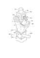
- the multi-joint robot 103 has joints 103A to 103F, and a mechanism unit 140 in which a workpiece gripping device and a deburring device are integrated is attached to an arm tip portion 103G of the most advanced joint 103F.
- the mechanism portion 140 includes a columnar base portion 141 attached to the arm tip portion 103G, a substantially U-shaped holder 142 connected to the base portion 141, and a first surface of the holder 142.
- a workpiece gripping hand portion 143 and a workpiece suction pad portion 144 disposed on the second surface of the holder 142 are provided, and the suction pad portion 144 is connected via a connection hose (not shown). Connected to a vacuum source.
- the work gripping hand portion 143 operates with an air cylinder (not shown).
- the deburring device 1 is attached to the third surface (lower surface in the figure) of the holder 142, and a flat blade cutter blade 10 is fixed to the tip of the holder 142, and the workpiece blade 130 on the workpiece receiving mechanism 105 is deburred by the cutter blade 10. 132 is removed.
- the workpiece receiving mechanism 105 includes a mechanism table 110 and a workpiece receiving jig 112 connected to the mechanism table 110 with a plurality of bolts 111. As shown in FIG. For example, a receiving groove that fits the protrusion of the workpiece 130 is formed in the placement portion 112A. The workpiece 130 is placed on the workpiece placement portion 112A by fitting the convex portion of the workpiece 130 into the receiving groove so as to drop from the solid line to the imaginary line. A suction port 112B for suction is formed in the workpiece placement unit 112A, and the suction port 112B is connected to a vacuum source via a connection hose 112C. When the workpiece 130 is placed on the workpiece placement unit 112A, the workpiece is sucked.
- the shape of the workpiece mounting portion 112A is determined in accordance with the convex shape of the workpiece 130, the burr shape generated on the workpiece, or the like. At least the burr generated on the workpiece 130 can be removed by the cutter blade 10, that is, the cutter The shape is set so as not to hinder the burr removal operation by the blade 10.
- the workpiece mounting unit 112A includes a support table 112D. When the workpiece shape to be molded is changed by changing the mold of the resin molding machine 101, the workpiece mounting unit corresponding to the workpiece shape is integrally formed from the support table 112D. The workpiece is replaced with another workpiece receiving jig 112 having the portion 112A. In the deburring system 100, the setup is changed by exchanging the workpiece receiving jig 112, and the setup time is shortened.
- FIG. 6 is a cross-sectional view of the resin molding machine 101.
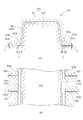
- 7A is a partially enlarged view of the workpiece 130 shown in FIG. 6 (when compression is completed), and
- FIG. 7B is a cross-sectional view showing the state where the mold shown in FIG. 7A is opened (when injected).
- 6 and 7 are different in form from the work in FIGS. 1 to 5, but for the sake of convenience of explanation, hereinafter, they will be described as the same form.
- the resin molding machine 101 described above includes a mold 155 including a fixed mold 151 provided in the fixed portion 101D (see FIG. 1) and a movable mold 153 provided in the movable portion 101E.
- the movable mold 153 moves the movable part 101E toward the fixed mold 151 of the fixed part 101D by the drive mechanism (or servo motor drive mechanism) having a direct pressure type or toggle type structure by hydraulic pressure, and compresses the work 130. Mold.
- the drive mechanism or servo motor drive mechanism having a direct pressure type or toggle type structure by hydraulic pressure, and compresses the work 130. Mold.
- the movable mold 153 extends on the mating surface 153A of the mold 153 in a flat plate shape corresponding to a so-called vertical burr in the direction in which the mold opens.
- a housing portion 153B for housing the overflow resin 130A is provided.
- the accommodating portion 153B is concave and is formed over a portion corresponding to the entire periphery of the workpiece 130 on the mating surface 153A of the movable mold 153. Further, when the resin injection gate is located on the mating surface 153A, the accommodating portion 153B is formed over a portion corresponding to the entire periphery of the work 130 including the gate.
- the depth T is 0.05 mm or more and the length L is 0.05 mm or more.
- the upper limit value of the length L is, for example, 1/2 of the depth T, and preferably 1/3 of the depth T. Each dimension is appropriately determined depending on the properties of the resin material and the size of the product.
- the movable mold 153 is separated from the fixed mold 151 in the opening direction by a predetermined dimension with the parting line P / L as a boundary (see FIG. 7B), and the molded product space (cavity) A predetermined amount of molten resin material is injected into 135. Thereafter, the movable mold 153 is moved toward the fixed mold 151, the parting lines P and L are aligned, and the mold between the fixed mold 151 and the movable mold 153 is clamped (see FIG. 7A). 130 is compression molded.
- the molten resin material may be injected into the molded product space 135 with a low pressure, and thereafter, the mold between the fixed mold 151 and the movable mold 153 may be clamped with a low pressure.
- the resin molding machine 101 is not limited to the above configuration, and may be a normal injection molding machine that injects a molten resin into a mold at a high pressure and clamps the high pressure.
- the overflow resin 130A formed by the accommodating portion 153B described above is a portion that is cut out in a deburring process described later, and the depth T and the length L are not limited to the above dimensions, and the material of the resin material, etc.
- the depth T and the length L are set appropriately according to the conditions or suitable for excision with a deburring device. If the depth T and the length L are too large, the resin is wasted, and if it is too small, deburring becomes difficult.
- resin molding by the resin molding machine 101 there are variations in the performance of the molding machine, the mold used therefor, the resin component, etc., and in particular, it is difficult to supply the optimum amount of resin into the cavity of the mold. Molding becomes unstable regardless of whether the amount is large or small.
- the overflow resin accommodating portion 153B is formed in the mold, when the amount of resin injected into the mold varies, the overflow resin fills the interior of the accommodating portion 153B and varies to the smaller amount. In this case, the amount of overflow resin entering the storage portion 153B is reduced, and the dispersion of the resin injection amount is automatically adjusted by the overflow resin amount, so that the resin amount in the cavity is stable and stable molding is possible.
- the overflow resin is allowed in this configuration, it is not necessary to suppress the generation of burrs during molding.
- the molten resin material is injected into the molded product space 135 at a low pressure, and then fixed.
- the mold 151 and the movable mold 153 are clamped at a low pressure, that is, when low pressure compression molding is performed, a resin molded product with higher quality can be manufactured.
- the required clamping force of the molding machine can be suppressed to 1/4 to 1/5 of the conventional one.
- the overflow resin 130 ⁇ / b> A corresponds to a conventional so-called burr and is synonymous with the burr 132.
- the overflow resin 130A by allowing the overflow resin 130A, the subsequent burr removal is almost complete, the finished resin molded product is clean, and there is a great difference in its purpose.
- FIG. 8 shows another embodiment of the resin molding machine.
- the resin molding machine 101 includes a fixed mold 159 provided in the fixed part 101D (see FIG. 1), a mold including a movable mold 158 and a movable mold 157 provided in the movable part 101E. 155.
- Reference numeral 181 denotes a hydraulic cylinder shaft coupled to the movable mold 157, and the movable mold 157 is opened or moved in the compression direction via the shaft 181.
- PW is a compression allowance.
- FIG. 8B at the time of compression completion
- the mating surface 157A includes an accommodating portion 157B that accommodates overflow resin 150A that extends in a flat plate shape in a direction in which the mold opens, corresponding to so-called vertical burrs.
- the accommodating portion 157B has a concave shape, and is formed over a portion corresponding to the entire periphery of the workpiece 150 on the mating surface 157A of the movable mold 157.
- the depth T is suitably 0.05 mm or more and the length L is 0.05 mm or more, for example, as in the above embodiment.
- the upper limit value of the length L is, for example, 1/2 of the depth T, and preferably 1/3 of the depth T. Each dimension is appropriately determined depending on the properties of the resin material and the size of the product.
- FIG. 9 shows a so-called horizontal burr form.
- the stationary mold 151 accommodates on the mating surface 151A of the mold 151 the overflow resin 130A that corresponds to a so-called horizontal burr and extends in a plate shape in a direction orthogonal to the direction in which the mold opens.
- 151B The accommodating portion 151 ⁇ / b> B has a concave shape, and is formed over a portion corresponding to the entire periphery of the workpiece 130 on the mating surface 151 ⁇ / b> A of the fixed mold 151.
- the depth T is, for example, 0.05 mm or more
- the length L is, for example, 0.05 mm or more.
- the upper limit value of the length L is, for example, 1/2 of the depth T, and preferably 1/3 of the depth T.
- the above dimensions are appropriately determined depending on the properties of the resin material and the size of the product. That is, the overflow resin 130A formed in the accommodating portion 151B is a portion that is cut out in a deburring process described later, and its depth T and length L are not limited to the above dimensions, and are cut out by a deburring device. Suitable depth T and length L are set. If the depth T and the length L are too large, the resin is wasted, and if it is too small, deburring becomes difficult.
- a plurality of gas vent holes 160 are formed in the mating surface 151A of the fixed mold 151 so as to be orthogonal to the direction in which the accommodating portion 151B extends.
- the gas vent holes 160 are gas vent holes for discharging the gas in the cavity 135, and are formed on the entire surface of the mating surface 151A at appropriate intervals in the circumferential direction.
- the gas is vented through the overflow resin 130A accommodated in the accommodating portion 151B during resin molding. Therefore, if a resin burn or the like occurs, it occurs in a portion of the overflow resin 130A, and the overflow resin 130A is removed in a deburring process described later, so that the resin burn or the like remains on the finished product.
- the workpiece 150 is a product with a bead 150 ⁇ / b> B, and the mating surface 153 ⁇ / b> A of the movable mold 153 is in a direction perpendicular to the mold opening direction corresponding to the horizontal burr. You may provide the accommodating part 153B which accommodates the overflow resin 150A extended in flat form.
- any of the above-described molds 155 is used, and at the time of resin molding, a molten resin material is injected into a molded product space (cavity) 135 at a low pressure or a high pressure, and then a fixed mold and a movable mold. The space is clamped at low or high pressure.
- a molten resin material is injected into a molded product space (cavity) 135 at a low pressure or a high pressure, and then a fixed mold and a movable mold. The space is clamped at low or high pressure.
- an intermediate product in which the overflow resins 130A and 150A are integrated with the parting surfaces of the workpieces 130 and 150 is molded.
- so-called conventional burrs are generated at the peripheral edges of the tips of the overflow resins 130A and 150A.
- FIG. 11 shows the deburring device 1.
- the deburring device 1 is attached to the third surface (lower surface in the drawing) of the holder 142 as described above.
- the deburring device 1 has a support 3 fixed to a third surface, and an air-driven slide table device 4 is fixed to the support 3.
- the slide table device 4 includes a fixed portion 4a fixed to the support body 3, support portions 4b and 4c fixed to both ends of the fixed portion 4a, a shaft 4d provided between the support portions 4b and 4c, and a shaft 4d. And a slidable slide portion 5.
- the slide portion 5 can reciprocate in a predetermined linear direction (arrow X direction), and the linear direction is a direction in which a lower surface of a so-called flat blade 10 can be pressed against a workpiece.
- 4e is a stopper.
- One support portion 4b is provided with an air supply port 4f
- the other support portion 4c is provided with an air discharge port 4g
- the air supply port 4f has a pressure regulator (not shown) for adjusting the pressure of supply air. ) Is connected.
- One end of the ultrasonic transducer holder 6 is attached to the slide unit 5.
- the other end of the ultrasonic transducer holder 6 is formed with a semi-annular holder portion 6a.
- the column of the ultrasonic transducer 7 is formed between the holder portion 6a and another semi-annular holder portion 6b.
- the ultrasonic transducer 7 is attached to the other end of the ultrasonic transducer holder 6 by sandwiching the portion 7a and connecting the holder portions 6a and 6b with bolts.
- a cutter blade 10 is fixed to the tip of the ultrasonic transducer 7 as shown in FIG.
- An ultrasonic unit (not shown) is connected to the ultrasonic vibrator 7 via a cord 7b (see FIG.
- the slide table device 4 constitutes a floating mechanism, and the cutter blade 10 at the tip of the deburring device 1 is movable in the direction of arrow A, that is, placed in a floating state with respect to a workpiece (resin molded product) described later.
- FIG. 13 shows the cutter blade 10 during the deburring operation.
- a workpiece 130 having a shape different from that of the workpiece 130 is illustrated.
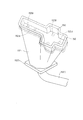
- the cutter blade 10 has a cutter blade body portion 10C on the front end side, and the cutter blade body portion 10C includes a front end surface 10F and a rear end surface 10R.
- the rear end surface 10R extends substantially parallel to the extension line of the ultrasonic transducer 7, and the front end surface 10F recedes from the extension line of the ultrasonic transducer 7 perpendicular to the feed direction B with a receding angle ⁇ .
- the cutter blade 10 is fixed to the ultrasonic vibrator 7 by either brazing or screwing.
- the cutter blade 10 can cut off the overflow resins 130A and 150A of the workpieces 130 and 150 formed using the above-described mold 155 or the like. For example, if it is FIG. 10, it cuts along the cut line L1, if it is FIG. 7, it cuts along the cut line L2, and if it is FIG. 8, it should just cut along the cut line L3.
- the resin molded product that is the work 130 is various, such as a care bed part, a copier part, a tool box, a heat insulating resin box, an automobile air spoiler, an automobile visor, an automobile center pillar, and an automobile interior sheet. .
- the cutter blade 10 abuts on the base (base) of the overflow resin 130 ⁇ / b> A (burr 132) formed on the partition line 121, for example.
- the front end face 10F of the cutter blade 10 has a curved surface corresponding to the root of the overflow resin 130A, for example, a cutting edge portion 10A having a width W of about several millimeters and a cutting edge corresponding to each surface portion 123A, 123B of the workpiece 130. And a copying section 10B having a shape.
- the width W of the cutting edge portion 10A is generally about 0.6 to 1 mm, but can be appropriately changed according to the shape of the burr formed on the workpiece.
- FIG. 14 is a cross-sectional view including the cutting blade portion 10A of the cutter blade.
- the distal end portion of the blade 10A1 formed at the foremost portion of the cutting edge portion 10A is an R curved surface portion 10B1 of the copying portion 10B formed on the front end surface 10F of the cutter blade 10.
- the position of the tip portion of the blade 10A1 coincides with the lower surface of the cutter blade main body portion 10C. Can be removed from the root.
- the shape is unstable as in the case of a resin component, or the burr formed in a curved shape is cut off.
- the cutter blade 10 does not bite into the material too much, and the occurrence of problems such as broken blades can be suppressed.
- the lower surface of the blade 10A1 of the cutting blade portion 10A extends in alignment with the lower surface of the cutter blade main body portion 10C, and a leveling portion 10A2 is formed on the lower surface.
- the leveling portion 10A2 is in contact with the workpiece 130 at a substantially constant pressure depending on the balance of air pressure in the slide portion 5. Thereby, the leveling part 10A2 presses the base portion of the overflow resin 130A left by the cutting edge part 10A against the work 130 side so that the vicinity of the partition line 121 of the work 130 is smoothed.
- the lower surface 10C1 of the cutter blade main body portion 10C configured as a portion further deeper than the leveling portion 10A2 of the cutter blade main body portion 10C is given a slight angle ⁇ and is separated from the work 130.
- the rear end surface 10R of the cutter blade 10 is in a state of being completely separated from the work 130.
- the deburring device 1 When the deburring device 1 is operated, for example, an operator actually moves the arm of the articulated robot 103 once or several times to perform direct teaching for storing path information corresponding to the movement path of the arm. Alternatively, a method of automatically generating route information using shape information created by a design system such as a CAD system using an automatic route generation system is employed.
- the path information obtained by the direct teaching or the path automatic generation system is not necessarily a correct path for each work 130 in the deburring operation when there is a large variation in the actual work 130 to be deburred.
- the deburring device 1 of the present configuration has the floating mechanism, and can deburr the cutter blade 10 against the workpiece with a slightly higher pressing force than planned, and performs copying control. Little work is required to correct the position. Therefore, the substantial processing time can be shortened.
- the multi-joint robot 103 takes out the workpiece (resin molded product) 130 before deburring from the resin molding machine 101 using the hand unit 143 shown in FIG. 2 according to direct teaching.
- the workpiece is transferred to the workpiece receiving jig 105.
- Overflow resin 130A is allowed for workpiece 130 of the intermediate product before deburring.
- the articulated robot 103 removes the overflow resin 130A of the workpiece 130 on the workpiece receiving jig 105 using the cutter blade 10 of the deburring device 1 shown in FIG.
- examples of the work 130 include a resin tool box, a resin heat insulation box, a resin component for a copying machine, and a resin component for an automobile.
- the multi-joint robot 103 has six-axis joints 103A to 103F so that the direction and driving direction of the cutter blade 10 of the arm tip 103G are optimized along the removal path of the overflow resin 130A. To control the operation. In this case, needless to say, the slide portion 5 of the arm tip portion 103G is in a floating state with respect to the workpiece 130.
- the pressure applied to the air supply port 4f is controlled, and the cutter blade 10 is applied to the workpiece 130 with a predetermined pressure. It is being pressed.
- the pressure applied to the air supply port can be automatically switched according to the posture of the cutter blade 10, and is always constant regardless of the posture of the cutter blade 10.
- the ultrasonic transducer 7 attached to the ultrasonic transducer holder 6 is driven to vibrate the cutter blade 10 with an amplitude of, for example, about 30 to 50 ⁇ m, while the copying unit 10B is moved to each surface portion 123A, It moves along 123B, and the cutter blade 10 is sent along the root of the overflow resin 130A formed on the partition line of the work 130 to cut the burrs, and at the same time, the surface after the cutting is leveled.
- the present invention is not limited to ultrasonic waves, and vibration may be applied with an amplitude of about 10 to 150 ⁇ m, for example.
- the articulated robot 103 takes out the workpiece 131 as a finished product after removing the overflow resin 130A from the workpiece receiving jig 105 using the suction pad portion 144 shown in FIG. It is discharged and discharged out of the system through the conveyor 109. Further, the overflow resin 130A removed by the deburring device 1 is discharged onto the deburring conveyor 107 through the inclined hopper 133 and discharged outside the system.
- the deburring device 1 can produce a finished product 131 having no secondary burrs after the removal of the overflow resin 130A. Therefore, the manual deburring work that has been performed manually is not required, and the deburring system can be completely automated, thereby reducing the cost of the molded product. In addition, since the overflow molding resin 130A is allowed to be generated in the mold of the resin molding machine 101 after fully automated, an expensive molding machine that suppresses the generation of burrs is not necessary. Also, the cost of the molded product can be reduced.
- overflow resin 130A is allowed at the intermediate product stage, so-called burrs are generated at the tip of overflow resin 130A, and deburring device 1 has a cutting edge corresponding to the root of overflow resin 130A.
- a cutter blade 10 having a portion 10A and a copying portion 10B that does not constitute a cutting edge corresponding to the surface portion of the intermediate product, and the cutter blade 10 is fed along the root of the overflow resin 130A while vibrating the cutter blade 10 Since the overflow resin 130A integrated with the intermediate product is excised together with burrs, a finished product without burrs can be easily manufactured.
- FIG. 15 shows another embodiment of the deburring device 1.
- the main body 215 of the tool holding means TH is attached to the arm tip 103G of the articulated robot 103, and the pressing means 231 is attached to the main body 215.
- the pressing means 231 includes an air slide table 232, and a tool holder 200 is attached to the tip of the air slide table 232.
- the tool holder 200 includes a motor 201, a support member 210, a spring 212, a support member 209, guide posts 207 and 208, a spring 211, and a holder fixing member 206.
- the holder fixing member 206 has a collar 205 of the tool holder 204. It is fixed.
- An end mill 203 penetrates inside the tool holder 204, and the end mill 203 is fixed to the chuck 202 of the output shaft of the motor 201.
- a V-shaped opening 204 ⁇ / b> A that the end mill 203 faces is formed on the outer periphery of the tool holder 204.
- the product form is taught to the articulated robot 103, and the tool holder 204 is pressed against the work by the operation of the air slide table 232, and the V-shaped opening 204 A of the tool holder 204 is copied.
- the burrs of the workpiece are removed by the end mill 203 facing the opening 204A while copying the copying surface of the workpiece.
- the tool holder 204 is floatingly supported by the springs 211 and 212, and the V-shaped wall surface of the opening 204A of the tool holder 204 functions as a copying portion.
- overflow resin 130A is integrally formed on the parting surface of the intermediate product, so that overflow resin 130A can be efficiently cut by end mill 203.
- the end mill 203 is mounted on the tool holder 204.
- the end mill 203 is not limited thereto, and the cutting tool may be a rotary bar having a large number of cutting edges formed on the outer periphery of the bar.
- FIG. 16 shows another embodiment of the deburring device 1.
- the deburring apparatus 1 is configured to remove the burrs that appear on the surface of the intermediate product. It is suitable for removing.
- reference numeral 301 denotes an arm of an articulated robot
- a floating mechanism 303 is arranged at the tip 301A of the arm 301.
- the floating mechanism 303 has a base 303A fixed to the tip 301A of the arm 301, and a slider 307 that is slidable in both directions of the arrow X1 and the arrow X2 via the linear bearing 305 is supported on the base 303A.
- a pair of left and right air cylinders 309 and 309 are connected to the slider 307.
- the slider 307 is constantly pressed in the direction of the arrow X1 by the air pressure, and when a pressure higher than the air pressure acts in the direction of the arrow X2, the slider 307 is pushed back, that is, It will be in a floating state.
- a stay 311 is fixed to the slider 307, and a nozzle body 313 for water cutting (or laser cutting) is supported at two points on the front edge of the stay 311 in the figure with a gap ⁇ 1 in the vertical direction in the figure.
- a support plate 315 is fixed to the lower edge of the stay 311 in the drawing, and a servo motor 317 is fixed to the support plate 315.
- An output shaft 317A of the servo motor 317 is connected to a ball screw 321 through a coupling 319, and a slider 325 is connected to the ball screw 321 through a screw nut 323.
- the slider 325 meshes with the linear bearing 327, and the linear bearing 327 is fixed to the support plate 315.
- a substantially U-shaped copying head 331 is swingably supported at the tip of the slider 325 via a pin 329, and the copying surface of the intermediate product 351 is provided at both ends of the copying head 331.
- a pair of copying rollers (cam followers) 333A and 333B that abut on 351A and roll are pivotally supported at a predetermined interval ⁇ 2. Between the pair of copying rollers 333A and 333B, the nozzle tip 313A of the nozzle body 313 is positioned. ), And the above-described overflow resin (burr) 351B formed integrally around the entire periphery of the intermediate product 351 is cut and removed.
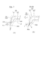
- FIG. 17A is a side view of the copying head
- FIGS. 17B and 17C are plan views thereof.
- a pedestal 332 is fixed to the tip of the slider 325 via a base 330
- a scanning head 331 is engaged with the pedestal 332 via a bearing 334
- the scanning head 331 is necked via a pin 329. It is supported freely.
- the bearing 334 is formed in a curved surface, and the arc radius R thereof is a curved surface having a radius around the nozzle tip 313A of the nozzle body 313. In this embodiment, as shown in FIGS.
- the copying head 331 swings around the pin 329 according to this inclination, and a pair of copying rollers 333A and 333B. Imitates the inclined straight line portion L2. Then, while copying the copying surface 351A of the intermediate product 351 with the copying rollers 333A and 333B, water (or laser) is output from the nozzle tip 313A, and the overflow resin 351B integrally formed around the entire periphery of the intermediate product 351 is cut. .
- the deburring device 1 is not limited to the above embodiments, and it is needless to say that any deburring device can be applied.
- the workpiece is deburred while the cutting tool is supported on the robot arm tip and the workpiece is fixed.
- the present invention is not limited to this.
- the workpiece is supported on the robot arm tip.
- the robot may be taught and the workpiece deburred as taught, with the cutting tool fixed.
- the tool is preferably a floating support.
- the robot supports the workpiece, and the tool is provided on a part of the gantry to perform processing as taught by the robot.
Landscapes
- Engineering & Computer Science (AREA)
- Mechanical Engineering (AREA)
- Manufacturing & Machinery (AREA)
- Physics & Mathematics (AREA)
- Thermal Sciences (AREA)
- Processing And Handling Of Plastics And Other Materials For Molding In General (AREA)
- Moulds For Moulding Plastics Or The Like (AREA)
- Injection Moulding Of Plastics Or The Like (AREA)
Abstract
Description
従来、固定金型又は可動金型のパーティング面に移動部材を設け、該移動部材をパーティング面に押しつけることで、パーティング面へのバリの発生を抑制した技術が提案されている(例えば、特許文献1参照)。
一方、従来、バリの根元に対応した切れ刃部と、製品の面部に対応した切れ刃を構成しない倣い部とを有するカッター刃を備え、該カッター刃を振動させながら、バリの根元に沿ってカッター刃を送って、該バリを、効率よく除去するバリ取り装置が提案されている(例えば、特許文献2参照)。また、倣いガイド部材にエンドミルを貫装し、倣いガイド部材をワークに押圧し、追従させた状態で、エンドミルでバリを切除する技術が提案されている(例えば、特許文献3参照)。
特許文献2,3では、製品面からのバリの突出高さが、ある程度の高さを有したときに、該バリを、効率よく除去できるものであって、仮に突出量があまりに少ないときには、バリを効率よく除去できない恐れがあった。
そこで、本発明の目的は、上述した従来の技術が有する課題を解消し、射出成形等において、バリの無い完成品を簡単に製造できる樹脂製品製造システム、製造方法、樹脂成形装置、及び金型を提供することにある。
本明細書では、樹脂成形機で製造したバリの除去されていない段階の製品を、中間製品と定義し、バリを除去した後の製品を、完成品と定義する。
この場合、前記バリ除去装置が、オーバーフロー樹脂の根元に対応した切れ刃部と、中間製品の面部に対応した切れ刃を構成しない倣い部とを有するカッター刃を備え、カッター刃を振動させながら、オーバーフロー樹脂の根元に沿ってカッター刃を送って該中間製品と一体化した該オーバーフロー樹脂を前記バリと共に切除してもよい。
この場合、樹脂成形機としては、射出成形機等の一般成形機のほか、低圧圧縮成形機、高圧圧縮成形機、発泡成形機、炭素繊維射出成型機等であってよい。発泡成型機に適用すれば、射出発泡成形時にオーバーフロー樹脂を設けることで、このオーバーフロー樹脂と共にバリを完全に切除できるという効果が得られる。また、炭素繊維の射出成型機でオーバーフロー樹脂を設けることで、例えば超音波により振動されるカッターによってバリをオーバーフロー樹脂と共に完全に除去できるという効果が得られる。
樹脂成形機等による樹脂成形では、成形機の構造や、それに使用する金型や、樹脂成分などにばらつきがあり、特に、金型のキャビティ内への最適な樹脂量の供給が難しく、樹脂量が多くても少なくても成形が不安定となる。
この発明では、金型にオーバーフロー樹脂の収容部を形成したため、樹脂量が多いときや少ないときには、収容部内のオーバーフロー樹脂量で自動調整されるため、キャビティ内の樹脂量は安定し、安定成形できる。
前記オーバーフロー樹脂を前記金型が開く方向と直交する方向に延出した横バリの発生方向に一体化してもよい。
前記オーバーフロー樹脂の収容部を通してガス抜きしてもよい。
オーバーフロー樹脂を、縦バリ、横バリの発生方向に一体化すれば、金型は、該金型の合わせ面にオーバーフロー樹脂を収容する収容部を形成するだけでよく、金型の製作が容易になると共に、オーバーフロー樹脂の収容部を通してガス抜きすれば、ガス抜きによるバリの発生や、樹脂焼け等の欠損が、オーバーフロー樹脂部分から先に集中し、これをバリと共に除去することで、完成品に欠点を残すことなく、樹脂製品を製造できる。
中間製品に生じたバリは、バリ取り装置で除去することになるため、バリ取り装置の工具の届く範囲に、バリを発生させることが望ましい。
上述した中間製品に生じるバリは、予め定めた位置、例えばパーティングラインの全周囲に計画された範囲に設定され、このバリをバリ取り装置で除去するため、例えば顕微鏡等により上記計画された範囲にバリの除去跡を追認できる。
バリ除去装置で除去するバリを含む中間製品を成形する樹脂成形装置において、合わせ面に中間製品の全周囲に対応する部位に亘って形成されるオーバーフロー樹脂を収容する収容部を有した金型を備え、前記金型で前記バリを含むオーバーフロー樹脂を全周囲に一体化した中間製品を成形してもよい。
バリ除去装置で除去するバリを含む中間製品を成形する樹脂成形装置の金型であって、合わせ面に中間製品の全周囲に対応する部位に亘って形成されるオーバーフロー樹脂を収容する収容部を有し、前記バリを含むオーバーフロー樹脂を全周囲に一体化した中間製品を成形してもよい。
図1において、100は樹脂製品製造システムを示す。該樹脂製品製造システム100は、樹脂成形機101と、ワーク把持装置及びバリ取り装置をアーム先端部に有した多関節ロボット103と、バリ取り前の中間製品としてのワーク130(図4参照)を載せるワーク受け機構105と、除去されたバリ132をシステム外に排出するバリ排出コンベア107と、バリ取り後の完成品としてのワーク131(図5参照)をシステム外に排出する完成品排出コンベア109とを有する。なお、図示は省略したが、完成品排出コンベア109の代わりに、完成品を収納する収納ラックを備えても良い。
この機構部140は、図2に示すように、アーム先端部103Gに装着される円柱状の基部141と、この基部141に連なる略コ字形のホルダ142と、このホルダ142の第1の面に配置されたワーク把持用のハンド部143と、該ホルダ142の第2の面に配置されたワーク吸着用の吸着パッド部144とを備え、吸着パッド部144は接続ホース(図示せず)を介して真空源に接続されている。ワーク把持用のハンド部143は、エアシリンダ(図示せず)で動作する。
ホルダ142の第3の面(図中下面)にはバリ取り装置1が取り付けられ、その先端には平刃のカッター刃10が固定され、カッター刃10でワーク受け機構105上のワーク130のバリ132が除去される。
ワーク載置部112Aには吸着用の吸気口112Bが形成され、吸気口112Bは接続ホース112Cを介して真空源に接続され、ワーク載置部112Aにワーク130が載置されると吸引によってワーク130が固定される。ワーク載置部112Aの形状は、ワーク130の凸部形状や、ワークに生じたバリ形状等に応じて決定され、少なくともワーク130に生じたバリをカッター刃10で除去可能な形状に、即ちカッター刃10によるバリ除去動作を阻害しない形状に設定されている。
ワーク載置部112Aは支持台112Dを備え、樹脂成形機101の型換え等により成形するワーク形状が変更された場合には、支持台112Dから上を一体に、ワーク形状に対応したワーク載置部112Aを備える別のワーク受け治具112に交換される。本バリ取りシステム100では、ワーク受け治具112の交換で段取り変えとなり、段取り時間の短縮が図られる。
上述した樹脂成形機101は、図6に示すように、固定部101D(図1参照)に設けた固定金型151と、可動部101Eに設けた可動金型153とからなる金型155を備え、可動金型153は可動部101Eを油圧による直圧式ないしトグル式の構造である駆動機構(或いはサーボモータ駆動機構)によって、固定部101Dの固定金型151に向けて移動し、ワーク130を圧縮成形する。
上記構成では、溶融樹脂材料を低い圧力で、成形品空間135に注入し、その後、固定金型151及び可動金型153間を、低い圧力で型締めしても良い。この場合、樹脂成形機101は、上記構成に限定されず、溶融樹脂を金型内に高圧注入し、高圧型締めする通常の射出成形機であっても良い。
しかも、各金型151,153間を低圧力で型締めする成形機を用いれば、該成形機の所要型締め力を、従来比1/4~1/5に抑制できる。
なお、本構成において、オーバーフロー樹脂130Aは従来のいわゆるバリに相当するものであり、バリ132と同義である。ただし、このオーバーフロー樹脂130Aを許容したことにより、その後のバリ除去がほぼ完全になり、樹脂成形品の仕上がりがきれいになり、その目的には大きな差異がある。
この樹脂成形機101は、図8Aに示すように、固定部101D(図1参照)に設けた固定金型159と、可動部101Eに設けた可動金型158および可動金型157からなる金型155を備えて構成されている。181は、可動金型157に連結された油圧シリンダのシャフトであり、シャフト181を介して、可動金型157が開かれ、または、圧縮方向に移動される。PWは、圧縮代である。
本実施の形態では、図8B(圧縮完了時)、図8C(射出時)に示すように、ワーク150が、玉縁150B付き製品となっており、可動金型157が、該金型157の合わせ面157Aに、いわゆる縦バリに対応する、金型が開く方向に平板状に延出したオーバーフロー樹脂150Aを収容する収容部157Bを備える。
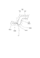
この収容部157Bは凹状であり、可動金型157の合わせ面157Aにおいて、ワーク150の全周囲に対応する部位に亘って形成される。その深さTは、上記の形態と同様に、例えば0.05mm以上、長さLは0.05mm以上が好適である。長さLの上限値は、例えば深さTの1/2であり、好ましくは深さTの1/3である。樹脂材料の性質や製品の大きさなどにより各寸法は適宜に決定される。
この場合、固定金型151が、該金型151の合わせ面151Aに、いわゆる横バリに対応する、金型が開く方向と直交する方向に平板状に延出したオーバーフロー樹脂130Aを収容する収容部151Bを備える。
この収容部151Bは凹状であり、固定金型151の合わせ面151Aにおいて、ワーク130の全周囲に対応する部位に亘って形成されている。その深さTは、例えば0.05mm以上であり、長さLは、例えば0.05mm以上である。長さLの上限値は、例えば深さTの1/2であり、好ましくは深さTの1/3である。樹脂材料の性質や、製品の大きさなどにより上記寸法は適宜に決定される。すなわち、収容部151Bで形成されるオーバーフロー樹脂130Aは、後述のバリ取り行程で切除される部位であり、その深さT及び長さLは、上記各寸法に限定されず、バリ取り装置で切除に適した、適宜の深さT及び長さLに設定される。深さT及び長さLは、大き過ぎると、樹脂が無駄になり、あまり小さいと、バリ取りが困難になる。
本実施の形態では、樹脂成形時において、収容部151Bに収容したオーバーフロー樹脂130Aを通してガス抜きされている。
従って、仮に、樹脂焼け等が発生するとすれば、オーバーフロー樹脂130Aの部位に発生し、該オーバーフロー樹脂130Aは、後述のバリ取り行程で除去されるため、完成品に対して、樹脂焼け等が残ることがない。この場合、図10に示すように、ワーク150が、玉縁150B付き製品となっており、可動金型153の合わせ面153Aに、横バリに対応する、金型が開く方向と直交する方向に平板状に延出したオーバーフロー樹脂150Aを収容する収容部153Bを備えても良い。
この段階を経て、ワーク130,150が樹脂成形されると、ワーク130,150のパーティング面に対し、オーバーフロー樹脂130A,150Aが一体化された中間製品が成形される。この場合、いわゆる従来のバリは、オーバーフロー樹脂130A,150Aの先端周縁部に発生する。
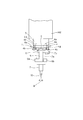
バリ取り装置1は、上述したように、ホルダ142の第3の面(図中下面)に取り付けられている。バリ取り装置1は、第3の面に固定される支持体3を有し、支持体3にはエア駆動タイプのスライドテーブル装置4が固定されている。スライドテーブル装置4は支持体3に固定される固定部4aと、固定部4aの両端に固定される支持部4b,4cと、各支持部4b,4c間に設けた軸4dと、軸4d上を摺動自在なスライド部5とを備えている。該スライド部5は所定の直線方向(矢印X方向)に往復動自在であり、該直線方向はいわゆる平刃のカッター刃10の下面をワークに対し押し付け可能な方向である。4eはストッパである。一方の支持部4bにはエア供給口4fが設けられ、他方の支持部4cにはエア排出口4gが設けられ、エア供給口4fには供給エアの圧力を調整する圧力調整器(図示せず)が接続されている。
なお、図13においては、説明の便宜のため、上記のワーク130(図2参照)とは異なる形状のワーク130を図示している。
カッター刃10は先端側にカッター刃本体部10Cを有し、このカッター刃本体部10Cは、前端面10Fおよび後端面10Rを備える。後端面10Rは、超音波振動子7の延長線とほぼ平行に延出し、前端面10Fは、送り方向Bに対して直角に交わる超音波振動子7の延長線から、後退角φで後退する。カッター刃10は超音波振動子7にロウ付け、或いはねじ止めの何れかにより固定される。
ワーク130である樹脂成形品は、例えば介護用ベッド部品、コピー機部品、ツールボックス、保温樹脂ボックス、自動車用エアスポイラー、自動車用バイザー、自動車用センターピラー、自動車用内装シートなど、多種多様である。カッター刃10は、例えばパーテーションライン121に形成されたオーバーフロー樹脂130A(バリ132)の基部(根元)に当接する。カッター刃10の前端面10Fには、オーバーフロー樹脂130Aの根元に対応した、例えば幅Wが数mm程度の切れ刃部10Aと、ワーク130の各面部123A,123Bに対応した切れ刃を構成しない曲面状の倣い部10Bと、を備える。切れ刃部10Aの幅Wは、0.6~1mm程度が一般的であるが、ワークに形成されたバリの形状などに応じて適宜変更が可能である。
この構成では、切れ刃部10A(ハッチングで示す部分。)の最先端部に形成された刃10A1の先端部が、カッター刃10の前端面10Fに形成された倣い部10BのR曲面部10B1と、カッター刃本体部10Cの下面とが交わる位置に延出して終端する。すなわち、倣い部10BのR曲面部10B1と、カッター刃本体部10Cの下面とが交わる位置まで、刃10A1の先端部が、カッター刃10の送り方向(矢印B方向)とは逆方向に後退している。本構成の切れ刃部10Aでは、刃10A1の先端部の位置が、カッター刃本体部10Cの下面と一致するため、該刃10A1の先端部が、オーバーフロー樹脂130Aの根元に深く入り、オーバーフロー樹脂130Aを根元から除去できる。
また、倣い部10Bがワークにどのように当接している状態であっても、さらに、樹脂部品のように形状が不安定な場合や、曲面形状に形成されたバリを切除する場合であっても、カッター刃10が材料に食い込みすぎることがなく、刃折れ等の不具合の発生を抑制することができる。
また、カッター刃本体部10Cの均し部10A2よりもさらに奥まった部分として構成されるカッター刃本体部10Cの下面10C1は、若干の角度θをつけられて、ワーク130から離間するようにされており、カッター刃10の後端面10Rは、ワーク130から完全に離間した状態となっている。
この結果、カッター刃10のうち、ワーク130に接触しているのは、均し部10A2に相当する部分だけとなり、切れ刃部10Aや倣い部10Bが他の部分の当たりにより浮き上がるのを防止することができる。
バリ取り装置1の作動時には、例えばオペレータが実際に一度ないし数度、多関節ロボット103のアームを動かしてアームの移動経路に相当する経路情報を記憶させるダイレクトティーチングを行う。或いは、経路自動生成システムを利用して、CADシステムなどの設計システムで作成した形状情報を利用して自動的に経路情報を生成する手法等が採用される。ただし、ダイレクトティーチングあるいは経路自動生成システムにより得られる経路情報は、実際のバリ取り対象のワーク130にバラツキが大きい場合、バリ取り動作において、各ワーク130に対し必ずしも正しい経路とはならない。
これに対し、本構成のバリ取り装置1は、上記フローティング機構を有し、予定よりも少し高い押圧力でカッター刃10をワークに押しつけてバリ取りでき、かつ倣い制御を行っているため、教示位置の修正に対する作業がほとんど発生しない。したがって、実質的な加工時間の短縮が図られる。
このようなワークに対し、多関節ロボット103においては、オーバーフロー樹脂130Aの除去経路に沿って、アーム先端部103Gのカッター刃10の向き、駆動方向が最適となるように、6軸関節103A~103Fの動作を制御する。
この場合において、アーム先端部103Gのスライド部5は、云うまでもなく、ワーク130に対して浮動状態である。
この状態で、超音波振動子ホルダ6に取り付けられた超音波振動子7が駆動され、カッター刃10を、例えば振幅30~50μm程度で振動させながら、倣い部10Bをワーク130の各面部123A,123Bに沿わせて移動し、ワーク130のパーテーションラインに形成されたオーバーフロー樹脂130Aの根元に沿ってカッター刃10を送ってバリを切除し、同時に切除後の面を均す。なお、超音波に限定せず、例えば振幅10~150μm程度の振動付与でも良い。最後に、多関節ロボット103が、オーバーフロー樹脂130Aの除去後の完成品としてのワーク131をワーク受け治具105から、図2に示す吸着パッド部144を用いて取り出し、完成品排出コンベア109上に排出し、該コンベア109を通じてシステム外に排出する。また、バリ取り装置1が除去したオーバーフロー樹脂130Aは、傾斜したホッパ133を経て、バリ排出コンベア107上に排出して、システム外に排出される。
よって、従来行っていた手作業での2次バリ除去の作業が不要になり、バリ取りシステムにおける完全自動化が可能になり、成形品コスト低減が図られる。また、完全自動化を図った上で、樹脂成形機101の金型にはオーバーフロー樹脂130Aの発生が許容されることになるため、バリの発生をきつく抑制した高価な成形機が不要になり、これによっても、成形品コストを低減できる。
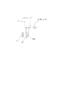
本実施の形態では、多関節ロボット103のアーム先端部103Gに、工具保持手段THの本体215が取り付けられ、本体215には、押圧手段231が取り付けられている。押圧手段231は、エアスライドテーブル232を含み、エアスライドテーブル232の先端には、工具ホルダ200が取り付けられている。工具ホルダ200は、モータ201、支持部材210、スプリング212、支持部材209、ガイド支柱207、208、スプリング211、及びホルダ固定部材206を備え、ホルダ固定部材206には、ツールホルダ204の鍔205が固定されている。ツールホルダ204の内側には、エンドミル203が貫通し、エンドミル203は、モータ201の出力軸のチャック202に固定されている。ツールホルダ204の外周には、エンドミル203が臨むV字形状の開口204Aが形成されている。このバリ取り装置1では、多関節ロボット103に製品形態をティーチィングして、エアスライドテーブル232の動作により、ツールホルダ204をワークに押圧しながら、ツールホルダ204のV字形状の開口204Aを倣い部として、該ワークの倣い面を倣いながら、この開口204Aに臨むエンドミル203によって、該ワークのバリを除去する。この場合、ツールホルダ204は、スプリング211,212によりフローティング支持されると共に、ツールホルダ204の開口204AのV字壁面は、倣い部として機能している。
この構成では、ツールホルダ204にエンドミル203が装着されているが、エンドミル203に限定されず、切削工具としては、バーの外周に多数の切れ刃が形成されたロータリーバーなどであってもよい。
上記樹脂成形機101が、炭素繊維強化プラスチック(CFRP)を使用して航空機や自動車部品等の中間製品を成形する場合、本実施形態によるバリ取り装置1は、該中間製品の表面に現れたバリを除去するのに好適である。
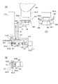
図16Aにおいて、301は多関節ロボットのアームを示し、このアーム301の先端301Aには、フローティング機構303が配置されている。フローティング機構303は、アーム301の先端301Aに固定された基部303Aを有し、この基部303Aには、リニアベアリング305を介して矢印X1及び矢印X2の双方向にスライド可能なスライダー307が支持され、スライダー307には、図16Cに示すように、左右一対のエアシリンダ309,309が連結されている。このエアシリンダ309,309の動作で、スライダー307は、エア圧により、常時、矢印X1の方向に押圧され、矢印X2方向にエア圧以上の圧力が作用すると、スライダー307が押し返され、すなわち、フローティング状態となる。
これらが変位手段を構成する。
スライダー325の先端には、図16Bに示すように、ピン329を介して略U字状の倣いヘッド331が首振り自在に支持され、倣いヘッド331の両端部には、中間製品351の倣い面351Aに当接し、転動する一対の倣いローラー(カムフォロアー)333A,333Bが、所定の間隔δ2をあけて軸支されている。
一対の倣いローラー333A,333Bの間には、ノズル本体313のノズル先端313Aが位置しており、倣いローラー333A,333Bで中間製品351の倣い面351Aを倣いながら、ノズル先端313Aからウォーター(又はレーザー)を出力し、中間製品351の全周囲に一体に形成された、上述のオーバーフロー樹脂(バリ)351Bを切断して除去する。
スライダー325の先端には、基台330を介して受け台332が固定され、この受け台332にはベアリング334を介して倣いヘッド331が係合し、この倣いヘッド331がピン329を介して首振り自在に支持されている。
ベアリング334は曲面で形成されており、その円弧半径Rがノズル本体313のノズル先端313Aを中心とした半径となる曲面である。
この実施の形態では、図17A及び図17Bに示すように、中間製品351の倣い面351Aが直線部L1の場合、サーボモーター317の機能を停止し、ノズル先端313Aの位置に対する一対の倣いローラー333A,333Bの位置(寸法W1)を固定し、フローティング機構303の推進力で、倣いローラー333A,333Bを、中間製品351の倣い面351Aに押圧し倣いながら、ノズル先端313Aからウォーター(又はレーザー)を出力し、中間製品351の全周囲に一体に形成されたオーバーフロー樹脂351Bを切断する。中間製品351の倣い面351Aが、図17Cに示すように、傾いた直線部L2であれば、この傾きに応じ、倣いヘッド331がピン329の回りを首振りし、一対の倣いローラー333A,333Bが、傾いた直線部L2を倣う。
そして、倣いローラー333A,333Bで中間製品351の倣い面351Aを倣いながら、ノズル先端313Aからウォーター(又はレーザー)を出力し、中間製品351の全周囲に一体に形成されたオーバーフロー樹脂351Bを切断する。
10 カッター刃
100 樹脂製品製造システム
101 樹脂成形機
130,150 ワーク
130A,150A オーバーフロー樹脂
151 固定金型
153 可動金型
155 金型
151A,153A 合わせ面
151B,153B 収容部
160 ガス抜き孔
Claims (8)
- 樹脂成形機で中間製品を成形し、該中間製品のバリをバリ除去装置で除去して完成品を製造する樹脂製品製造システムにおいて、
前記樹脂成形機が、合わせ面において中間製品の全周囲に対応する部位に亘って形成されるオーバーフロー樹脂を収容する収容部を有した金型を備え、該金型により前記オーバーフロー樹脂を全周囲に一体化した中間製品を成形すると共に、
前記バリ除去装置が、前記中間製品の全周囲に一体化した該オーバーフロー樹脂を前記バリと共に切除して完成品を製造する、
ことを特徴とする樹脂製品製造システム。 - 前記オーバーフロー樹脂を前記金型が開く方向に延出した縦バリの発生方向に一体化したことを特徴とする請求項1に記載の樹脂製品製造システム。
- 前記オーバーフロー樹脂を前記金型が開く方向と直交する方向に延出した横バリの発生方向に一体化したことを特徴とする請求項1に記載の樹脂製品製造システム。
- 前記オーバーフロー樹脂の収容部を通してガス抜きすることを特徴とする請求項1乃至3のいずれか一項に記載の樹脂製品製造システム。
- 樹脂成形機で中間製品を成形し、該中間製品のバリを除去して完成品を製造する樹脂製品製造方法において、
合わせ面に中間製品の全周囲に対応する部位に亘って形成されるオーバーフロー樹脂を収容する収容部を有した金型により該オーバーフロー樹脂を全周囲に一体化した中間製品を成形する過程と、
前記中間製品の全周囲に一体化した前記オーバーフロー樹脂を前記バリと共に切除して前記完成品を製造する過程と
を備えたことを特徴とする樹脂製品製造方法。 - 前記オーバーフロー樹脂の収容部を通してガス抜きすることを特徴とする請求項5に記載の樹脂製品製造方法。
- バリ除去装置で除去するバリを含む中間製品を成形する樹脂成形装置において、
合わせ面に中間製品の全周囲に対応する部位に亘って形成されるオーバーフロー樹脂を収容する収容部を有した金型を備え、
前記金型で前記バリを含むオーバーフロー樹脂を全周囲に一体化した中間製品を成形することを特徴とする樹脂成形装置。 - バリ除去装置で除去するバリを含む中間製品を成形する樹脂成形装置の金型であって、
合わせ面に中間製品の全周囲に対応する部位に亘って形成されるオーバーフロー樹脂を収容する収容部を有し、
前記バリを含むオーバーフロー樹脂を全周囲に一体化した中間製品を成形することを特徴とする樹脂成形装置の金型。
Priority Applications (5)
| Application Number | Priority Date | Filing Date | Title |
|---|---|---|---|
| US13/061,349 US9321193B2 (en) | 2009-05-11 | 2009-11-06 | Resin product manufacturing system, manufacturing method, resin molding machine and mold |
| CN200980123531.7A CN102066071B (zh) | 2009-05-11 | 2009-11-06 | 树脂产品制造系统、制造方法、树脂成型装置以及模具 |
| EP09844582.8A EP2322334B1 (en) | 2009-05-11 | 2009-11-06 | Mold for producing resin product and production method |
| ES09844582T ES2733960T3 (es) | 2009-05-11 | 2009-11-06 | Molde para producir producto de resina y procedimiento de producción |
| KR1020117003963A KR101311645B1 (ko) | 2009-05-11 | 2009-11-06 | 수지 제품 제조 시스템, 제조 방법, 수지 성형 장치 및 금형 |
Applications Claiming Priority (2)
| Application Number | Priority Date | Filing Date | Title |
|---|---|---|---|
| JP2009-114728 | 2009-05-11 | ||
| JP2009114728A JP4491041B1 (ja) | 2009-05-11 | 2009-05-11 | 樹脂製品製造システム及び製造方法 |
Publications (1)
| Publication Number | Publication Date |
|---|---|
| WO2010131308A1 true WO2010131308A1 (ja) | 2010-11-18 |
Family
ID=42351940
Family Applications (1)
| Application Number | Title | Priority Date | Filing Date |
|---|---|---|---|
| PCT/JP2009/005917 Ceased WO2010131308A1 (ja) | 2009-05-11 | 2009-11-06 | 樹脂製品製造システム、製造方法、樹脂成形装置、及び金型 |
Country Status (7)
| Country | Link |
|---|---|
| US (1) | US9321193B2 (ja) |
| EP (1) | EP2322334B1 (ja) |
| JP (1) | JP4491041B1 (ja) |
| KR (1) | KR101311645B1 (ja) |
| CN (1) | CN102066071B (ja) |
| ES (1) | ES2733960T3 (ja) |
| WO (1) | WO2010131308A1 (ja) |
Cited By (1)
| Publication number | Priority date | Publication date | Assignee | Title |
|---|---|---|---|---|
| US8740608B2 (en) | 2011-04-05 | 2014-06-03 | Nihon Shoryoku Kikai Co., Ltd. | Workpiece removal and finishing device |
Families Citing this family (17)
| Publication number | Priority date | Publication date | Assignee | Title |
|---|---|---|---|---|
| EP2869986B1 (fr) * | 2012-07-06 | 2018-09-19 | Compagnie Plastic Omnium | Moule pour former une piece de vehicule automobile en materiau polymere |
| FR2999468B1 (fr) * | 2012-12-14 | 2015-05-29 | Plastic Omnium Cie | Cale pour moule a compression a etancheite amelioree |
| KR101462417B1 (ko) * | 2013-06-04 | 2014-11-17 | 에이테크솔루션(주) | 캐비티 주위에 댐 구조가 구비된 사출성형금형 |
| WO2017119465A1 (ja) | 2016-01-08 | 2017-07-13 | 帝人株式会社 | 繊維強化樹脂成形体の製造方法 |
| CN106113427B (zh) * | 2016-08-20 | 2018-06-19 | 苏州玖圣塑料科技有限公司 | 一种气阀式热流道模具及利用该模具制造成品的方法 |
| JP6762844B2 (ja) * | 2016-10-28 | 2020-09-30 | タイガースポリマー株式会社 | 管状樹脂成形体の製造方法 |
| CN107685415A (zh) * | 2017-08-02 | 2018-02-13 | 广州蓝圣智能科技有限公司 | 一种用于注塑件三维空间边缘上毛刺去除的自动化系统 |
| JP7045872B2 (ja) * | 2018-02-05 | 2022-04-01 | 川崎重工業株式会社 | 筐体の製作方法 |
| JP7121272B2 (ja) * | 2018-07-31 | 2022-08-18 | キョーラク株式会社 | 構造体の製造方法 |
| JP7117264B2 (ja) * | 2019-04-16 | 2022-08-12 | 株式会社ブリヂストン | ベントホール清掃装置及びベントホール清掃方法 |
| KR102937557B1 (ko) * | 2020-04-29 | 2026-03-10 | (주)엘엑스하우시스 | 차량용 플라스틱 사출품 중간재, 차량용 플라스틱 사출품 및 그의 제조방법 |
| DE112021004620T5 (de) * | 2020-09-04 | 2023-06-15 | AGC Inc. | Verfahren zur herstellung einer glasplatte mit einem harzrahmen für einfahrzeugfenster und vorrichtung zur herstellung einer glasplatte mit einemharzrahmen für ein fahrzeugfenster |
| JP2022189011A (ja) * | 2021-06-10 | 2022-12-22 | 株式会社神戸製鋼所 | 金属樹脂複合体を製造するための金型、装置、および方法 |
| CN115339044B (zh) * | 2022-08-03 | 2025-06-13 | 青岛海士豪塑胶有限公司 | 一种注塑系统及方法 |
| CN116100753B (zh) * | 2023-02-13 | 2023-08-22 | 广州市旭胜模具有限公司 | 一种可调节的汽车外壳注塑模具 |
| FR3146089B1 (fr) * | 2023-02-23 | 2026-02-20 | Safran Nacelles | Dispositif de thermocompression pour la fabrication de pieces mecaniques |
| CN117681382B (zh) * | 2023-11-10 | 2024-07-12 | 襄阳光瑞汽车零部件有限公司 | 一种注塑模具及轻量化保险杠注塑设备 |
Citations (6)
| Publication number | Priority date | Publication date | Assignee | Title |
|---|---|---|---|---|
| JPH0658349U (ja) * | 1993-01-22 | 1994-08-12 | 横浜ゴム株式会社 | 試験用ゴム試料の加硫用金型 |
| JPH07241890A (ja) | 1994-03-07 | 1995-09-19 | Japan Steel Works Ltd:The | 射出圧縮成形方法及び装置 |
| JPH1024460A (ja) * | 1996-07-11 | 1998-01-27 | Mitsubishi Materials Corp | 薄肉製品の射出成形方法 |
| JP2002239824A (ja) | 2001-02-09 | 2002-08-28 | Nippon Shoryoku Kikai Kk | 自動バリ取り装置およびそれに使用する工具保持装置 |
| JP2005007609A (ja) * | 2003-06-16 | 2005-01-13 | Toyo Tire & Rubber Co Ltd | ゴム成形品の製造用金型構造 |
| JP2008030251A (ja) | 2006-07-27 | 2008-02-14 | Nippon Shoryoku Kikai Kk | バリ取り装置およびカッター刃 |
Family Cites Families (22)
| Publication number | Priority date | Publication date | Assignee | Title |
|---|---|---|---|---|
| US2148079A (en) * | 1936-07-23 | 1939-02-21 | Goodrich Co B F | Mold for making pliable plastic articles |
| CH567927A5 (ja) * | 1974-08-21 | 1975-10-15 | Schiesser Ag | |
| AT357898B (de) | 1977-02-10 | 1980-08-11 | Semperit Ag | Halbfertigartikel |
| FR2532239A1 (fr) * | 1982-08-30 | 1984-03-02 | Renault | Procede d'ebavurage automatique de pieces en preimpregne polyester |
| DE3444030A1 (de) | 1984-12-03 | 1986-06-05 | Siemens AG, 1000 Berlin und 8000 München | Verfahren und vorrichtung zum fertigen von weitgehend gratfreien formteilen sowie zugehoeriges spritz- oder giessteil |
| JPS62220308A (ja) | 1986-03-22 | 1987-09-28 | Kawasaki Yukou Kk | 油圧プレスによる反応射出成形方法 |
| US5008062A (en) * | 1988-01-20 | 1991-04-16 | Siemens Solar Industries, L.P. | Method of fabricating photovoltaic module |
| JP2953631B2 (ja) | 1990-12-25 | 1999-09-27 | 本田技研工業株式会社 | 反応射出成形型 |
| GB2260932B (en) * | 1991-10-22 | 1995-10-25 | Honda Motor Co Ltd | Molding apparatus for producing synthetic resin molded product |
| KR0131140B1 (ko) * | 1992-06-30 | 1998-04-13 | 미요시 도시오 | 수지성형품의 수지성형 피복방법 및 그 방법에 채용되는 수지성형 피복장치 |
| US5564714A (en) | 1993-02-23 | 1996-10-15 | Three Bond Co., Ltd. | Rubber-like molded product with support frame |
| AU7633298A (en) * | 1997-05-30 | 1998-12-30 | Woodbridge Foam Corporation | Vented mold and method for producing a molded article |
| KR19990016491U (ko) * | 1997-10-28 | 1999-05-25 | 정몽규 | 사출 성형시 공기압이 배출되는 금형 구조 |
| DE10122959A1 (de) | 2001-05-11 | 2002-11-21 | West Pharm Serv Drug Res Ltd | Pharmazeutischer Spritzenkolben sowie Verfahren und Vorrichtung zu dessen Herstellung |
| JP3947088B2 (ja) * | 2002-11-01 | 2007-07-18 | 富士通株式会社 | 電子機器筐体および該筐体の製造に用いる射出成形装置 |
| CN1171710C (zh) * | 2002-11-25 | 2004-10-20 | 林齐 | 不饱和聚酯树脂透明铸封方法 |
| CN1504318A (zh) * | 2002-11-29 | 2004-06-16 | 上海纯青实业有限公司 | 一种塑料成型的方法 |
| NL1026739C2 (nl) | 2004-07-29 | 2006-01-31 | Fico Bv | Maldeel voor het omhullen van elektronische componenten. |
| CN1746081A (zh) * | 2004-09-06 | 2006-03-15 | 上海紫华容器包装有限公司 | 包装用抗菌塑瓶 |
| KR20090111310A (ko) * | 2007-02-20 | 2009-10-26 | 히다치 막셀 가부시키가이샤 | 열경화성수지로 이루어지는 성형품의 제조방법 및 사출 성형장치 |
| JP4887195B2 (ja) * | 2007-03-28 | 2012-02-29 | マクセルファインテック株式会社 | 金型、液状樹脂射出成形方法および光学素子 |
| JP4231895B2 (ja) * | 2008-06-23 | 2009-03-04 | 日本省力機械株式会社 | バリ取り装置 |
-
2009
- 2009-05-11 JP JP2009114728A patent/JP4491041B1/ja active Active
- 2009-11-06 KR KR1020117003963A patent/KR101311645B1/ko active Active
- 2009-11-06 US US13/061,349 patent/US9321193B2/en active Active
- 2009-11-06 ES ES09844582T patent/ES2733960T3/es active Active
- 2009-11-06 CN CN200980123531.7A patent/CN102066071B/zh active Active
- 2009-11-06 WO PCT/JP2009/005917 patent/WO2010131308A1/ja not_active Ceased
- 2009-11-06 EP EP09844582.8A patent/EP2322334B1/en active Active
Patent Citations (6)
| Publication number | Priority date | Publication date | Assignee | Title |
|---|---|---|---|---|
| JPH0658349U (ja) * | 1993-01-22 | 1994-08-12 | 横浜ゴム株式会社 | 試験用ゴム試料の加硫用金型 |
| JPH07241890A (ja) | 1994-03-07 | 1995-09-19 | Japan Steel Works Ltd:The | 射出圧縮成形方法及び装置 |
| JPH1024460A (ja) * | 1996-07-11 | 1998-01-27 | Mitsubishi Materials Corp | 薄肉製品の射出成形方法 |
| JP2002239824A (ja) | 2001-02-09 | 2002-08-28 | Nippon Shoryoku Kikai Kk | 自動バリ取り装置およびそれに使用する工具保持装置 |
| JP2005007609A (ja) * | 2003-06-16 | 2005-01-13 | Toyo Tire & Rubber Co Ltd | ゴム成形品の製造用金型構造 |
| JP2008030251A (ja) | 2006-07-27 | 2008-02-14 | Nippon Shoryoku Kikai Kk | バリ取り装置およびカッター刃 |
Non-Patent Citations (1)
| Title |
|---|
| See also references of EP2322334A4 * |
Cited By (1)
| Publication number | Priority date | Publication date | Assignee | Title |
|---|---|---|---|---|
| US8740608B2 (en) | 2011-04-05 | 2014-06-03 | Nihon Shoryoku Kikai Co., Ltd. | Workpiece removal and finishing device |
Also Published As
| Publication number | Publication date |
|---|---|
| KR20110043706A (ko) | 2011-04-27 |
| ES2733960T3 (es) | 2019-12-03 |
| JP2010260313A (ja) | 2010-11-18 |
| JP4491041B1 (ja) | 2010-06-30 |
| EP2322334A1 (en) | 2011-05-18 |
| EP2322334B1 (en) | 2019-04-17 |
| CN102066071A (zh) | 2011-05-18 |
| EP2322334A4 (en) | 2015-08-19 |
| US9321193B2 (en) | 2016-04-26 |
| US20110193258A1 (en) | 2011-08-11 |
| KR101311645B1 (ko) | 2013-09-25 |
| CN102066071B (zh) | 2015-07-29 |
Similar Documents
| Publication | Publication Date | Title |
|---|---|---|
| JP4491041B1 (ja) | 樹脂製品製造システム及び製造方法 | |
| CN101909843B (zh) | 毛刺去除系统、毛刺去除装置以及切削刀具 | |
| JP5613864B2 (ja) | 加工装置 | |
| JP4231895B2 (ja) | バリ取り装置 | |
| JP4955823B1 (ja) | ワーク取り出し仕上げ装置 | |
| CN105592988A (zh) | 切割刀具和加工装置 | |
| JP4586105B2 (ja) | 樹脂製品製造システム、製造方法、樹脂成形装置、及び金型 | |
| JP4169769B2 (ja) | バリ取り装置およびカッター刃 | |
| JP4685976B1 (ja) | スクレイパー式バリ取り装置 | |
| TWI530379B (zh) | 毛邊移除裝置 | |
| TWI426015B (zh) | 毛邊移除系統及毛邊移除裝置 | |
| JP2006123273A (ja) | バリ取り方法及び装置 | |
| TWI602675B (zh) | 切除器刀刃 | |
| JP2008142821A (ja) | 切削加工用超音波ホーン及び超音波切削加工装置並びに超音波切削加工方法 | |
| HK1186702B (en) | Cutter blade and deburring system | |
| CN221754985U (zh) | 一种超声波焊接机 |
Legal Events
| Date | Code | Title | Description |
|---|---|---|---|
| WWE | Wipo information: entry into national phase |
Ref document number: 200980123531.7 Country of ref document: CN |
|
| 121 | Ep: the epo has been informed by wipo that ep was designated in this application |
Ref document number: 09844582 Country of ref document: EP Kind code of ref document: A1 |
|
| ENP | Entry into the national phase |
Ref document number: 20117003963 Country of ref document: KR Kind code of ref document: A |
|
| WWE | Wipo information: entry into national phase |
Ref document number: 13061349 Country of ref document: US Ref document number: 2009844582 Country of ref document: EP |
|
| NENP | Non-entry into the national phase |
Ref country code: DE |