WO2010131322A1 - 車両用シート - Google Patents
車両用シート Download PDFInfo
- Publication number
- WO2010131322A1 WO2010131322A1 PCT/JP2009/058760 JP2009058760W WO2010131322A1 WO 2010131322 A1 WO2010131322 A1 WO 2010131322A1 JP 2009058760 W JP2009058760 W JP 2009058760W WO 2010131322 A1 WO2010131322 A1 WO 2010131322A1
- Authority
- WO
- WIPO (PCT)
- Prior art keywords
- seat
- width direction
- skeleton
- paddle
- vehicle seat
- Prior art date
- Legal status (The legal status is an assumption and is not a legal conclusion. Google has not performed a legal analysis and makes no representation as to the accuracy of the status listed.)
- Ceased
Links
Images








Classifications
-
- B—PERFORMING OPERATIONS; TRANSPORTING
- B60—VEHICLES IN GENERAL
- B60N—SEATS SPECIALLY ADAPTED FOR VEHICLES; VEHICLE PASSENGER ACCOMMODATION NOT OTHERWISE PROVIDED FOR
- B60N2/00—Seats specially adapted for vehicles; Arrangement or mounting of seats in vehicles
- B60N2/90—Details or parts not otherwise provided for
- B60N2/986—Side-rests
-
- B—PERFORMING OPERATIONS; TRANSPORTING
- B60—VEHICLES IN GENERAL
- B60R—VEHICLES, VEHICLE FITTINGS, OR VEHICLE PARTS, NOT OTHERWISE PROVIDED FOR
- B60R21/00—Arrangements or fittings on vehicles for protecting or preventing injuries to occupants or pedestrians in case of accidents or other traffic risks
- B60R21/02—Occupant safety arrangements or fittings, e.g. crash pads
- B60R21/16—Inflatable occupant restraints or confinements designed to inflate upon impact or impending impact, e.g. air bags
- B60R21/20—Arrangements for storing inflatable members in their non-use or deflated condition; Arrangement or mounting of air bag modules or components
- B60R21/207—Arrangements for storing inflatable members in their non-use or deflated condition; Arrangement or mounting of air bag modules or components in vehicle seats
-
- B—PERFORMING OPERATIONS; TRANSPORTING
- B60—VEHICLES IN GENERAL
- B60N—SEATS SPECIALLY ADAPTED FOR VEHICLES; VEHICLE PASSENGER ACCOMMODATION NOT OTHERWISE PROVIDED FOR
- B60N2/00—Seats specially adapted for vehicles; Arrangement or mounting of seats in vehicles
- B60N2/58—Seat coverings
- B60N2002/5808—Seat coverings comprising opening zones for airbags
-
- B—PERFORMING OPERATIONS; TRANSPORTING
- B60—VEHICLES IN GENERAL
- B60R—VEHICLES, VEHICLE FITTINGS, OR VEHICLE PARTS, NOT OTHERWISE PROVIDED FOR
- B60R21/00—Arrangements or fittings on vehicles for protecting or preventing injuries to occupants or pedestrians in case of accidents or other traffic risks
- B60R21/02—Occupant safety arrangements or fittings, e.g. crash pads
- B60R21/16—Inflatable occupant restraints or confinements designed to inflate upon impact or impending impact, e.g. air bags
- B60R21/20—Arrangements for storing inflatable members in their non-use or deflated condition; Arrangement or mounting of air bag modules or components
- B60R21/215—Arrangements for storing inflatable members in their non-use or deflated condition; Arrangement or mounting of air bag modules or components characterised by the covers for the inflatable member
- B60R2021/21537—Arrangements for storing inflatable members in their non-use or deflated condition; Arrangement or mounting of air bag modules or components characterised by the covers for the inflatable member characterised by hinges
Definitions
- the present invention relates to a vehicle seat.
- An object of the present invention is to obtain a vehicle seat capable of satisfactorily deploying a side airbag in a configuration in which the side support mechanism and the side airbag are built in the seat back.
- a vehicle seat includes a skeleton member that forms a skeleton of a side support of a seat bag, and a skeleton drive mechanism that receives an adjustment force to displace the skeleton member in the seat width direction. And a side which is provided in a folded state so as to overlap the skeleton member in a side view in the seat width direction in the seat bag, and is expanded toward the front in the front-rear direction of the seat while being inflated by receiving a gas supply An airbag and a skeletal movable structure for displacing a part or all of the skeleton member including at least an outer portion in the seat width direction to the inner side in the seat width direction by a deployment pressure of the side airbag.
- the skeleton drive mechanism when adjusting the side support, an adjustment force is applied to the skeleton drive mechanism manually or automatically. Then, the skeleton driving mechanism displaces the skeleton member in the seat width direction, thereby adjusting the side support.
- the skeleton drive mechanism may be any mechanism that displaces the skeleton member in at least one of the sheet width directions.
- the side airbag In the vehicle seat, when the side airbag is inflated and deployed, the skeleton member is displaced inward in the seat width direction by the deployment pressure of the side airbag. Thereby, the side airbag is prevented or suppressed from being hindered by the skeletal member, and is successfully deployed toward the front in the front-rear direction of the seat.
- the side airbag can be satisfactorily deployed in the configuration in which the side support mechanism and the side airbag are built in the seat back.
- the skeletal movable structure is configured so that the side support adjusting mechanism allows the skeleton member to move inward in the seat width direction while the skeleton drive mechanism allows relative displacement of the skeleton member inward in the seat width direction.
- the structure can be displaced, and further includes a biasing member that biases the skeletal member outward in the seat width direction, so that the skeleton member can be moved in the seat longitudinal direction by the deployment pressure of the side airbag. It is good also as a structure comprised so that this frame
- the skeleton drive mechanism can drive the skeleton member inward in the seat width direction while allowing the skeleton member to move inward in the seat width direction.
- the skeleton member is at least a sheet with respect to the skeleton drive mechanism.
- the inner side in the width direction is not restrained.
- the skeleton member is displaced toward the inside in the seat width direction with a low load as the side airbag is deployed, and the side airbag can be favorably deployed toward the front in the front-rear direction of the seat. Can do.
- the skeleton drive mechanism is configured to press the rear part of the skeleton member in the seat longitudinal direction outwardly in the seat width direction by an unconstrained pressing member against the skeleton member, thereby causing the skeleton member to move in the seat longitudinal direction.
- the skeleton movable structure is configured such that the front portion of the skeleton member in the front-rear direction of the seat is pressed forward in the front-rear direction of the seat by the deployment pressure of the airbag. Accordingly, the front portion of the skeleton member may be configured to be displaced inward in the seat width direction against the urging force of the urging member.
- the pressing member presses the rear part of the skeleton member in the seat front-rear direction outward in the seat width direction. .
- the front part of the skeleton member in the sheet width direction is displaced inward in the sheet width direction. Since the pressing member of the skeleton drive mechanism is not restrained with respect to the skeleton member, the skeleton member does not interfere with the pressing member when the front portion of the skeleton member is pressed forward of the seat by the deployment pressure of the side airbag. It is smoothly displaced inward in the sheet width direction.
- the skeletal movable structure is configured to displace the skeleton member inward in the seat width direction by releasing the connection state of the skeleton member to the skeleton drive mechanism by the deployment pressure of the side airbag. It is good also as composition.
- the skeleton member when the side airbag is inflated and deployed, the coupled state of the skeleton member to the skeleton drive mechanism is released by the deployment pressure, and the skeleton member is displaced inward in the seat width direction. For this reason, in this vehicle seat, the skeleton member is displaced inward in the seat width direction with a low load, and the side airbag can be favorably deployed toward the front in the seat front-rear direction.
- the connection structure (adjustment force transmission structure) etc. of a skeleton member and a skeleton drive mechanism there are few restrictions with respect to the connection structure (adjustment force transmission structure) etc. of a skeleton member and a skeleton drive mechanism.
- the side support adjusting mechanism is configured such that the skeleton drive mechanism is connected to the skeleton member at a plurality of positions, and the skeleton movable structure is a partially connected state of the skeleton member to the skeleton drive mechanism.
- the skeleton member is displaced inward in the seat width direction by releasing the connection state of the other linking part of the skeleton member to the skeleton drive mechanism by the deployment pressure of the side airbag while maintaining the skeleton driving mechanism. It is good also as composition.
- the skeleton member is held on the seat back side when the side airbag is deployed. be able to.
- the skeletal movable structure is configured such that the outer part of the skeleton member in the seat width direction is a movable part that is deformed or relatively displaced with respect to the inner part, and the movable part is a deployment pressure of the side airbag.
- the movable portion may be displaced inward in the seat width direction by being pressed forward in the seat front-rear direction.
- the movable portion of the skeleton member is displaced inward in the seat width direction by receiving the deployment pressure of the side airbag.
- the side support adjustment mechanism may further include a drive source that generates an adjustment force of the side support.
- the side support can be adjusted by power without depending on the force (manual) of the seated person.
- adjustment of the side support by power and displacement of the framework member at a low load when the side airbag is deployed can be achieved. Can be achieved.
- the skeleton member is disposed in the region of the abdomen of the seated occupant in the seat vertical direction, and the side airbag can restrain the waist from the chest or shoulder to the seated occupant in the seat vertical direction. It is good also as a structure which is set as the structure expanded by this.
- the side airbag is deployed in a height region from the chest or shoulder of the seated occupant to the waist, and thus protects the seated occupant well.
- the side airbag is deployed by wrapping on either side in the seat vertical direction with respect to the skeleton member in a side view, but the skeleton member is displaced inward in the seat width direction by the deployment pressure of the side airbag as described above. As a result, the side airbag is satisfactorily deployed.
- the vehicle seat according to the present invention has an excellent effect that the side airbag can be satisfactorily deployed in the configuration in which the side support mechanism and the side airbag are built in the seat back.
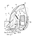
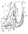
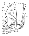
- FIG. 2 is an enlarged bottom cross-sectional view illustrating a deployed state of a side airbag that constitutes the vehicle seat according to the first embodiment of the present invention. It is bottom sectional drawing which expands and shows the side support part which comprises the vehicle seat which concerns on the 1st Embodiment of this invention. It is a bottom sectional view expanding and showing an adjustment state of a side support part which constitutes a vehicular seat concerning a 1st embodiment of the present invention.
- 1 is a perspective view showing a schematic configuration of a vehicle seat according to a first embodiment of the present invention.
- FIG. 5 is a bottom sectional view taken along line 5A-5A in FIG.
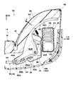
- bottom sectional drawing which expands and shows the side support part which comprises the vehicle seat which concerns on the 3rd Embodiment of this invention. It is bottom sectional drawing which expands and shows the expansion
- arrow FR, arrow UP, arrow RH, and arrow LH appropriately described in each figure are the right side that is one side of the forward direction (traveling direction), the upward direction, and the vehicle width direction of the vehicle to which the vehicle seat 10 is applied, respectively.
- the left side, which is the other side, is shown, and corresponds to the front side, the top side, the right side and the left side of the seat width direction.
- FIG. 4 is a perspective view showing a schematic overall configuration of the vehicle seat 10.
- FIG. 5 is a cross-sectional view taken along line 5-5 shown in FIG.
- the vehicle seat 10 includes a seat cushion 12 on which a vehicle occupant is seated, and a seat back 14 having a lower end connected to the seat rear end side of the seat cushion 12. Has been.
- the seat back 14 includes a backrest 16 that supports the upper body of the occupant from the rear of the vehicle, and a pair of left and right side supports 18 that project forward from both ends of the backrest 16 in the seat width direction. .
- the pair of left and right side supports 18 support the occupant's upper body from the side.
- the seat back 14 is configured such that a cushion material 36 and a skin material 54 described later are supported by the seat back frame 14 ⁇ / b> A, and a rear portion thereof is covered with the back board 15.
- the side airbag module 20 and the side support adjusting mechanism 22 are built in the seat back 14 constituting the vehicle seat 10.
- the side airbag module 20 and the side support adjusting mechanism 22 are supported by a seat back frame 14 ⁇ / b> A constituting the seat back 14.
- the side airbag module 20 is disposed in a side support 18 on the outer side in the vehicle width direction of the seat back 14.
- the side support adjusting mechanism 22 is configured to adjust the left and right side supports 18 (angle and interval). This will be specifically described below.
- the side airbag module 20 is in a folded state and receives a gas supply to inflate and deploy toward the front of the vehicle, and an inflator 26 that generates gas to be supplied to the side airbag 24 by being actuated.
- the side airbag 24 in the folded state and the cover member 28 that covers the inflator 26 are included.
- the inflator 26 is provided in a posture along the seat vertical direction in the rear portion of the folded side airbag 24 in the seat longitudinal direction. The inflator 26 is actuated when a side collision (that is unavoidable) of a vehicle to which the vehicle seat 10 is applied is detected.
- the side airbag module 20 is configured such that the gas generated by the inflator 26 is directly supplied to the side airbag 24. Further, the side airbag module 20 is fastened to the side frame portion 14B extending in the seat vertical direction at the outer end in the seat width direction of the seat back frame 14A by a bolt 26A provided on the inflator 26 and a nut (not shown). Yes. The cover material 28 is easily broken as the side airbag 24 is inflated.
- the side airbag 24 is located in the vertical direction (side view) of the seat, as shown in FIG. 6A, from the waist L to the chest C of the seated occupant P of the vehicle seat 10, or as shown in FIG. 6B.
- the seat occupant is deployed in the region from the waist L to the shoulder S.
- the deployed side airbag 24 is partitioned into upper and lower chambers 24U and 24L in a side view.
- the internal pressure is kept higher in the lower chamber 24L corresponding to the waist L of the seated occupant P than in the upper chamber 24U corresponding to the chest C of the seated occupant P.
- it is divided into three chambers 24U, 24C, and 24L that are upper, middle, and lower in a side view.
- the internal pressure is kept higher than the intermediate chamber 24C corresponding to the chest C of the seated occupant P. It has come to be. Since the side airbag 24 having the upper and lower divided or three divided structures as described above has a known configuration, detailed description thereof is omitted.
- the side support adjusting mechanism 22 shown in FIGS. 4 and 5 has a pair of left and right paddles 30 as skeleton members, and the left and right paddles 30 form the skeleton portions of the left and right side supports 18.
- the side support 18 is adjusted by displacing the paddle 30 in the seat width direction. More specifically, as shown in FIGS. 2 and 3, the paddle 30 supports a portion constituting the side support 18 in the cushion material (pad) 36 from the outside in the seat width direction and from the rear in the seat front-rear direction. Yes.
- the restraining state of the seated occupant P by the left and right side supports 18 (its position, posture, and shape) is adjusted by displacing the paddle 30 in the seat width direction.
- the paddle 30 in this embodiment is arranged in the middle portion in the vertical direction of the side support 18 (seat back 14).
- the left and right paddles 30 are disposed in a region including the abdomen (between the waist L and the chest C) of the seated occupant P of the vehicle seat 10. That is, the paddle 30 is disposed so as to overlap the side airbag module 20 (the folded side airbag 24) in the seat vertical direction.
- the paddle 30 has a portion projecting outward in the seat width direction with respect to the side frame portion 14 ⁇ / b> B within the adjustment range of the left and right side supports 18, and this portion is a side airbag.
- the module 20 is configured to be positioned in front of the seat.
- the side support adjusting mechanism 22 displaces the paddle 30 in the seat width direction in response to the adjusting force from the power unit 32 that generates adjusting force for adjusting the left and right side supports 18. It further includes a paddle drive mechanism 34 as a skeleton drive mechanism to be moved, and a return spring 35 as a biasing member that biases the paddle 30 to a predetermined position.
- the side support adjustment mechanism 22 is configured to adjust the side support 18 against the urging force of the return spring 35 by converting the adjustment force of the power unit 32 into the displacement force of the paddle 30 by the paddle drive mechanism 34. .
- the left and right paddles 30 and the paddle drive mechanism 34 are basically configured symmetrically, so that the paddles 30 on the left and right sides (on the side where the side airbag module 20 is arranged in the illustrated example), The paddle drive mechanism 34 will be described.
- the paddle drive mechanism 34 has a bracket 38 that is fixed on the inner side in the seat width direction with respect to the side frame portion 14B.
- the bracket 38 has an elongated hole (guide groove) 38A extending along the sheet width direction in the inner part of the sheet width direction, and an elongated hole (guide groove) 38B extending along the sheet front-rear direction in the outer part of the sheet width direction. Is formed.
- guide pins 30A and 30B protruding from the rear end side of the paddle 30 in the front-rear direction of the seat are slidably inserted.
- the paddle 30 is displaced with respect to the bracket 38 while maintaining the state in which the guide pins 30A and 30B are inserted into the long holes 38A and 38B of the bracket 38, whereby the paddle 30 in the front-rear direction of the seat supporting the cushion material 36 is obtained.
- the cushion support portion 30C is displaced in the seat width direction.
- the return spring 35 is a tension coil spring that is stretched between the cushion support portion 30C of the paddle 30 and the side frame portion 14B. Due to the urging force of the return spring 35, the paddle 30 is biased to a position where the guide pin 30A contacts the inner end 38AI of the long hole 38A and the guide pin 30B contacts the rear end 38BR of the long hole 38B. .
- This position is an initial position in which the cushion support portion 30C of the paddle 30 is located on the outermost side in the seat width direction and on the rear end side of the seat, and between the left and right side supports 18 in a state where the left and right paddles 30 are located at the initial position. The interval of is made the widest.
- the paddle drive mechanism 34 constituting the side support adjustment mechanism 22 is configured to displace the paddle 30 against the urging force of the return spring 35 by pressing the guide pin 30A outward in the seat width direction.
- the paddle 30 is guided by the guide holes 30A and 30B in the long holes 38A and 38B of the bracket 38, while the cushion support portion 30C is positioned inward in the seat width direction (in the direction of arrow A). ) Is displaced (posture change).
- the paddle drive mechanism 34 is configured to convert the adjustment force of the power unit 32 into a pressing force against the guide pin 30A by the operation cable 40.
- the operation cable 40 is a covered cable mainly composed of an inner cable 42 and an outer cable 44 that covers a portion excluding both ends of the inner cable 42.
- the outer end 42A of the inner cable 42 in the seat width direction is locked to the bracket 38 (or the side frame portion 14B) on the outer side of the outer end 38AO in the seat width direction of the long hole 38A.
- the inner end 42B of the inner cable 42 in the sheet width direction is pulled inward in the sheet width direction by the power portion 32 as will be described later.
- the outer end surface 44A in the sheet width direction is brought into non-restraining contact with the guide pins 30A from the inner side in the sheet width direction, and the inner end portion 44B in the sheet width direction is seated via the fixture 46 It is fixedly supported by the back frame 14A.
- the support structure for the fixture 46 and the seat back frame 14A is not shown.
- the inner cable 42 penetrates the guide pin 30A in order to secure the contact between the outer cable 44 and the guide pin 30A.
- the operation cable 40 is slack with the paddle 30 positioned at the initial position.
- the inner cable 42 is pulled inward in the seat width direction (in the width direction opposite to the paddle 30 to be operated) of the inner cable 42, thereby loosening the outer cable 44.
- the guide pin 30A is pressed outward in the sheet width direction.
- the paddle 30 is attached to the return spring 35. It is displaced to the initial position side by force.
- the power unit 32 includes a motor 48 as a driving source and a cable pulling mechanism 50 that converts the torque of the motor 48 into a pulling force inward in the seat width direction of the inner cable 42.
- the motor 48 is supported on the seat back frame 14A via a bracket 52 (this support structure is not shown), and an electric motor capable of rotating the output shaft 48A along the seat width direction forward and backward around the axis by power feeding.
- the cable pulling mechanism 50 is a feed screw mechanism that converts the rotation of the output shaft 48A into a linear motion along the sheet width direction.
- the cable pulling mechanism 50 includes a screw 50A that is elongated in the sheet width direction and rotated about its own axis by a motor 48, and a nut 50B that is screwed to the screw 50A.
- the power unit 32 is shared by the left and right paddles 30 (paddle drive mechanism 34), and the left and right screws 50A and the nuts 50B screwed to these screws are mutually reverse screws.
- the cable pulling mechanism 50 causes the left and right nuts 50B to approach each other (displace inward in the seat width direction), and the left and right screws 50A are moved by the motor 48.
- the left and right nuts 50B are separated from each other (displaced outward in the seat width direction).
- the inner end 42B of the inner cable 42 in the seat width direction is connected to the corresponding left and right nuts 50B. Therefore, in the vehicle seat 10, when the screw 50A is rotated forward by the motor 48, the inner cable 42 is pulled and the outer cable 44 presses the guide pin 30A outward in the vehicle width direction, as shown in FIG. The paddle 30 is displaced in front of the seat and inward in the seat width direction. Thereby, as above-mentioned, it is the structure adjusted so that the left and right side support 18 may mutually adjoin.
- the motor 48 of the power unit 32 rotates the screw 50 ⁇ / b> A in the forward and reverse directions in response to an operation of a hand switch (not shown) by the seated occupant P.
- the paddle 30 is configured such that the displacement in the direction of the arrow A is not restricted by the paddle drive mechanism 34 in which the outer cable 44 is in contact with the guide pin 30A from the inner side in the seat width direction. ing. For this reason, when a load that can resist the urging force of the return spring 35 is input to the cushion support portion 30C from the rear side of the seat, the paddle 30 resists the urging force of the return spring 35 in the direction of arrow A. It is designed to be displaced. At this time, the inner cable 42 of the operation cable 40 slides with respect to the guide pin 30A or bends between the guide pin 30A and the outer end 38AO in the sheet width direction of the long hole 38A as shown in FIG.
- the configuration is such that almost no resistance force is generated against the displacement of the paddle 30 in the direction of arrow A (the generated resistance force is small).
- the outer cable 44 is configured such that no resistance force is generated against the displacement of the paddle 30 in the arrow A direction because the rear portion of the paddle 30 is separated in accordance with the displacement of the paddle 30 in the arrow A direction.
- the urging force of the return spring 35 is sufficiently smaller than the pressing force (the pressing force based on the deployment pressure) that presses the paddle 30 forward of the seat as the side airbag 24 is deployed. Therefore, in the vehicle seat 10, when the inflator 26 of the side airbag module 20 is activated, the paddle 30 pressed against the side airbag 24 is displaced in the direction of arrow A as shown in FIG. Yes.
- the paddle drive mechanism 34 (the pressing structure of the guide pin 30A by the outer cable 44 of the operation cable 40) that can drive the paddle 30 in the direction of arrow A while making the paddle 30 unconstrained in the direction of arrow A is movable in the frame.
- the outer cable 44 corresponds to a pressing member in the present invention.
- a tear portion 56 that is torn along with the deployment of the side airbag 24 is formed in the skin material 54 constituting the seat back 14.
- the tier portion 56 is a sewing portion of the skin material 54 along the seat vertical direction, and is disposed at the front end in the seat front-rear direction and the outer end in the seat width direction of the side support 18.
- the tier portion 56 is cleaved by receiving the deployment pressure of the side airbag 24 via the paddle 30 (cushion material 36), thereby allowing the deployment of the side airbag 24 to the front of the seat. ing.
- the tier portion 56 may be cleaved by a webbing or the like that receives tension as the side airbag 24 is inflated.
- the screw 50A is rotated forward by the motor 48.
- the left and right nuts 50B are respectively displaced inward in the seat width direction, and the inner cable 42 is pulled, whereby the outer cable 44 presses the guide pins 30A outward in the seat width direction.
- the left and right paddles 30 are displaced in the respective arrow A directions together with the cushion material 36 and the skin material 54 constituting the side support 18, the angle of the side support 18 with respect to the backrest 16 is reduced, and the distance between the left and right side support 18 is increased. It narrows.
- the inflator 26 of the side airbag module 20 is activated. Then, the side airbag 24 is supplied with the gas generated by the inflator 26 and is inflated and deployed.
- the paddle 30 receiving the pressing force based on the deployment pressure of the side airbag 24 at the cushion support portion 30C is displaced in the direction of arrow A, and the cushion support portion 30C is retracted from the deployment region (deployment path) of the side airbag 24. Is done. Further, the tier portion 56 is cleaved by the deployment pressure of the side airbag 24.
- the side airbag 24 is deployed in front of the seat, which is the outside of the side support 18.
- the seated occupant P of the vehicle seat 10 is protected against side collision by the side airbag 24 deployed on the outer side in the vehicle width direction (collision side).
- the paddle 30 is displaced in the direction of arrow A by the deployment pressure of the side airbag 24, so that the deployment of the side airbag 24 forward of the seat is allowed.
- the paddle drive mechanism 34 does not restrain displacement of the paddle 30 in the direction of arrow A (restraint force is extremely small)
- the side airbag 24 can be used in a short time from the start of gas supply.
- the paddle 30 is pushed away and developed in front of the seat. For this reason, the seated occupant P is well protected against side collision.
- the side airbag 24 can be satisfactorily deployed in the configuration in which the side airbag module 20 and the side support adjustment mechanism 22 are built in the side support 18 of the seat back 14. it can.
- the side support 18 is driven by the power of the motor 48 in the configuration in which the side airbag 24 can be satisfactorily deployed as described above. Can be adjusted easily.
- the holding state of the paddle 30 by the bracket 38 is maintained.
- the paddle 30 is not separated from the seatback 14 with the operation of the side airbag module 20.
- the vehicle seat 10 includes the side airbag 24 having the lower two-part or three-part structure, the chest part C while firmly supporting the seated occupant P at the waist L or the waist L and the shoulder S. Can be supported with an appropriate load (reaction force).
- the paddle 30 disposed so as to overlap the side airbag 24 in a side view is retracted from the deployment region of the side airbag 24 in a plan view by the deployment pressure of the side airbag 24, thereby The large side airbag 24 that can protect the occupant P can be deployed well.
- FIG. 7 is a bottom cross-sectional view corresponding to FIG. 1 showing a main part when the side airbag 24 is deployed in the vehicle seat 60 according to the second embodiment of the present invention.
- the non-operating state of the side airbag module 20 in the vehicle seat 60 is shown in a bottom sectional view corresponding to FIG.
- the vehicle seat 60 is partially displaced by the deployment pressure of the side airbag 24 instead of the paddle 30 that is displaced in the direction of the arrow A as a whole by the deployment pressure of the side airbag 24.
- the vehicle seat 10 according to the first embodiment is different in that the paddle 61 is provided.
- the paddle 61 includes a base portion 62 that is supported by the bracket 38 so as to be capable of relative displacement (adjustment operation), and a movable portion 64 that supports an outer portion in the seat width direction of the side support 18 in the cushion material 36. That is, the paddle 61 is configured such that the paddle 30 is divided into two at the cushion support portion 30C.
- the base 62 has guide pins 62A and 62B corresponding to the guide pins 30A and 30B, and the guide pins 62A and 62B are supported by the bracket 38 so as to be capable of relative displacement in the direction of arrow A and in the opposite direction.
- the movable portion 64 is supported so as to be capable of relative angular displacement with respect to the base portion 62 via a hinge shaft 65 along the seat vertical direction.
- the movable portion 64 is disposed in front of the seat with respect to the side airbag module 20, and the hinge shaft 65 is disposed on the inner side in the seat width direction with respect to the side airbag module 20.
- the paddle 61 has a stopper 66 that restricts relative angular displacement of the movable portion 64 relative to the base portion 62 toward the rear side of the seat (in the direction of arrow B in FIG. 8).
- the paddle 61 is configured to have substantially the same shape as the paddle 30 in a state where the stopper 66 functions. This state of the paddle 61 is referred to as a normal state.
- the paddle 61 has a leaf spring 68 that urges the movable portion 64 in the direction of arrow B. By the urging force of the leaf spring 68, the paddle 61 is held in a normal state without rattling.
- the paddle 61 resists the urging force of the urging force of the leaf spring 68 in FIG.
- the relative angular displacement is made around the hinge shaft 65 in the direction indicated by.
- the movable portion 64 is displaced forward of the seat and inward in the seat width direction, and is retracted from the deployment region of the side airbag 24. Therefore, in this embodiment, the structure in which the movable portion 64 is supported so as to be capable of relative angular displacement about the hinge shaft 65 with respect to the base portion 62 corresponds to the skeletal movable structure in the present invention.
- Other configurations of the vehicle seat 60 are the same as the corresponding configurations of the vehicle seat 10 including a portion not shown.
- the paddle 61 functions in the same manner as the paddle 30 in the vehicle seat 10 while maintaining the normal posture.
- the inflator 26 is activated during a side collision of the vehicle to which the vehicle seat 60 is applied, the movable portion 64 is pressed forward by the pressing force based on the deployment pressure of the side airbag 24.
- the movable portion 64 of the paddle 61 is angularly displaced in the direction of arrow D against the urging force of the leaf spring 68 as shown in FIG.
- the movable portion 64 retracted from the deployment region is smaller than the vehicle seat 10 in which the entire paddle 30 is retracted from the deployment region of the side airbag 24. For this reason, in the vehicle seat 60, the deployment region of the side airbag 24 can be secured in a shorter time and with a lower load.
- FIG. 9 is a bottom cross-sectional view showing a main part of a vehicle seat 70 according to the third embodiment of the present invention.
- the deployed state of the side airbag 24 is indicated by an imaginary line.
- the vehicle seat 70 includes a side support adjusting mechanism 74 that drives the paddle 71 bidirectionally, instead of the side support adjusting mechanism 22 having the paddle driving mechanism 34 that drives the paddle 30 in one direction.
- the vehicle seat 60 according to the second embodiment is different.
- the paddle 71 has a base 72 and a movable part 64.
- the base portion 72 is supported by the side frame portion 14 ⁇ / b> B via the bracket 76.
- the base portion 72 is supported by the bracket 76 so as to be rotatable around a guide pin 72A provided on the rear end side of the sheet and on the inner end side in the sheet width direction.
- the bracket 76 allows rotation of the base 72 around the guide pin 72A and displacement in the sheet width direction by inserting the guide pin 72A into a long hole 76A elongated in the sheet width direction.
- the side support adjusting mechanism 74 is configured to drive an intermediate portion of the base 72 in the seat width direction (that is, the seat front-rear direction) in the seat front-rear direction.
- the cushion support part part which supports the cushion material 36 comprised by a part of base 72 and the movable part 64
- a connecting portion between the base 72 and the side support adjusting mechanism 74 is a ball joint 78.
- the side support adjusting mechanism 74 includes a motor 80 as a drive source and a linear motion mechanism 82 as a skeleton drive mechanism that converts the rotation of the motor 80 into a linear motion in the front-rear direction of the seat.
- the linear motion mechanism 82 includes a pressing rod 82A connected to the base 72 via a ball joint 78, and a gear box 82B that converts the rotation of the motor 80 into a linear motion of the pressing rod 82A.
- the gear box 82B is provided on the rotating shaft of the motor 80, for example, a nut screwed to a screw formed on the pressing rod 82A, a worm wheel formed on the outer periphery of the nut, and a mesh with the worm wheel.
- the motor 80 in the rotation axis direction
- the motor 80 can be disposed along the sheet width direction or the sheet vertical direction (in the example of FIG. 9, the sheet width direction).
- the ball joint 78 also allows rotation of the pressing rod 82 ⁇ / b> A around its own axis relative to the base 72.
- Other configurations of the vehicle seat 70 are the same as the corresponding configurations of the vehicle seat 60 including a portion not shown.
- the same effect can be obtained basically by the same operation as the vehicle seat 60 (vehicle seat 10) according to the second embodiment.
- the paddle 71 is driven by the driving force of the side support adjusting mechanism 74 when the space between the left and right side supports 18 is narrowed or widened. For this reason, the vehicle seat 70 can be configured without the return spring 35.
- the vehicle seat 70 is configured such that the base portion 72 is driven by the side support adjusting mechanism 74 because the movable portion 64 is displaced in the direction of the arrow D by the pressing force based on the deployment pressure of the side airbag 24 at the time of a side collision. be able to. That is, in the vehicle seat 70, the deployment path of the side airbag 24 can be secured without relying on the configuration (paddle drive mechanism 34) that displaces the paddle 61 inwardly in the seat width direction.
- FIG. 10 is a bottom cross-sectional view corresponding to FIG. 1 showing a main part when the side airbag 24 is deployed in the vehicle seat 90 according to the fourth embodiment of the present invention.
- the non-operating state of the side airbag module 20 in the vehicle seat 90 is shown in a bottom sectional view corresponding to FIG.
- the vehicle seat 90 is partially separated from the bracket 38 instead of the paddle 30 that is displaced in the direction of arrow A while maintaining the guided state with the bracket 38 by the guide pins 30A and 30B.
- the vehicle seat 10 according to the first embodiment is different from the vehicle seat 10 according to the first embodiment in that the paddle 92 is provided.
- the paddle 92 has substantially the same shape as the paddle 30 as a whole, and corresponds to a guide pin 92A corresponding to the guide pin 30A, a slit 92B formed at a position corresponding to the guide pin 30B, and a cushion support portion 30C. And a cushion support portion 92C.
- the slit 92B is opened substantially rearward of the seat in plan view, and is detachably coupled (fitted) to a guide pin 94 that is guided in a long hole 38B of the bracket 38 in a retaining state.
- the paddle 92 described above receives a load on the front side of the seat that is greater than or equal to a predetermined value at the cushion support portion 92C, the periphery of the slit 92B is deformed and the coupling with the guide pin 94 is released. It is designed to be rotationally displaced (displaced in the direction of arrow E). Therefore, in this embodiment, the fitting structure with the guide pin 94 in the slit 92B corresponds to the skeleton movable structure in the present invention.
- Other configurations of the vehicle seat 90 are the same as the corresponding configurations of the vehicle seat 10 including portions not shown.
- the same effect can be obtained basically by the same operation as the vehicle seat 10 according to the first embodiment.
- the paddle 92 is partly separated from the bracket 38 and retracted from the deployment region of the side airbag 24. Therefore, in the vehicle seat 90, the displacement amount of the paddle 92 for retraction (compared to the vehicle seat 10 retracted from the deployment region of the side airbag 24 while the entire paddle 30 is guided by the bracket 38 ( Stroke) is small. On the other hand, since the coupling state of the guide pin 92 ⁇ / b> A with the bracket 38 is maintained, the paddle 92 is not separated from the seat back 14 with the operation of the side airbag module 20.
- FIG. 12 is a bottom cross-sectional view corresponding to FIG. 1 illustrating a main part when the side airbag 24 is deployed in the vehicle seat 100 according to the fourth embodiment of the present invention.
- the non-operating state of the side airbag module 20 in the vehicle seat 100 is shown in a bottom sectional view corresponding to FIG.
- the vehicle seat 100 includes a side support adjusting mechanism 74 that drives the paddle 102 in both directions instead of the side support adjusting mechanism 22 having the paddle driving mechanism 34 that drives the paddle 92 in one direction. This is different from the vehicle seat 90 according to the fourth embodiment.
- the paddle 102 is configured such that the base 72 and the movable portion 64 of the paddle 71 are integrated (fixed).
- a guide pin 102 ⁇ / b> A provided at the inner end in the seat width direction and in the vicinity of the rear end in the seat front-rear direction is inserted into the long hole 76 ⁇ / b> A of the bracket 76.
- the paddle 102 moves the cushion support portion 102B in the seat width direction when the pressing rod 82A of the side support adjusting mechanism 74 connected to the substantially center portion in the seat width direction (that is, the substantially center portion in the seat front-rear direction) moves in the seat front-rear direction. It is configured to be displaced in the direction.
- the connecting portion between the paddle 102 and the pressing rod 82A is a ball joint 104 that functions in the same manner as the ball joint 78.
- the ball joint 104 is configured such that the paddle 102 side and the linear motion mechanism 82 side are separated as shown in FIG. 12 when a load greater than a predetermined value on the front side of the seat is applied to the cushion support portion 102B.
- the ball joint 104 is configured by a ball portion 104A formed at the tip of the pressing rod 82A and a fitting slit 104B formed in the paddle 102 and detachably coupled (fitted) to the ball portion 104A.
- Other configurations of the vehicle seat 100 are the same as the corresponding configurations of the vehicle seat 90 including a portion not shown.
- the same effect can be obtained basically by the same operation as the vehicle seat 90 (vehicle seat 10) according to the fourth embodiment.
- the paddle 102 is driven by the driving force of the side support adjusting mechanism 74 when the space between the left and right side supports 18 is narrowed or widened. For this reason, the vehicle seat 100 can be configured without the return spring 35.
- the vehicle seat 100 has a configuration in which the paddle 102 is driven by the side support adjusting mechanism 74 because the cushion support portion 102B is displaced in the direction of arrow E by the pressing force based on the deployment pressure of the side airbag 24 in the case of a side collision. can do. That is, in the vehicle seat 100, the deployment path of the side airbag 24 can be secured without relying on a configuration (paddle drive mechanism 34) that displaces the paddle 102 inwardly in the seat width direction.
- a configuration (paddle drive mechanism 34) that displaces the paddle 102 inwardly in the seat width direction.
- the side airbag 24 has a two-part or three-part structure.
- the present invention is not limited to this, and for example, the side airbag 24 may have a single chamber.
- the example in which the side airbag 24 is provided in the vehicle width direction outer side portion (near side) of the seat back 14 is shown.
- this invention is not limited to this,
- the side airbags in the vehicle width direction may be configured to receive gas supply from the common inflator 26.
- the paddle drive mechanism 34 and the linear motion mechanism 82 are configured using a feed screw mechanism.
- the present invention is not limited to this.
- the paddle drive mechanism 34 and the linear motion mechanism 82 may be configured using a rack and pinion mechanism, a linear motor, or the like.
- the inner end 42B in the sheet width direction 42 and the paddles 71 and 92 may be driven.
- the outer cable 44 presses the guide pins 30A, 62A, and 92A outward in the sheet width direction, thereby causing the paddle 30 and the like to be displaced inward in the sheet width direction.
- the present invention is not limited to this, and for example, a configuration in which a movable portion that deforms (bends or the like) the base portion 62 may be provided.
- the example in which the side support 18 is adjusted by the driving force of the motors 48 and 80 has been shown.
- the present invention is not limited to this.
- the seat occupant P may manually apply an operating force to adjust the side support 18 (drive the paddles 30, 62, 72, 92, and 102).
Landscapes
- Engineering & Computer Science (AREA)
- Mechanical Engineering (AREA)
- Aviation & Aerospace Engineering (AREA)
- Transportation (AREA)
- Seats For Vehicles (AREA)
- Air Bags (AREA)
Abstract
Description
図7には、本発明の第2の実施形態に係る車両用シート60におけるサイドエアバッグ24展開時の要部が図1に対応する底面断面図にて示されており、図8には、車両用シート60におけるサイドエアバッグモジュール20の非作動状態が図2に対応する底面断面図にて示されている。これらの図に示される如く、車両用シート60は、サイドエアバッグ24の展開圧によって全体的に矢印A方向に変位されるパドル30に代えて、サイドエアバッグ24の展開圧によって部分的に変位されるパドル61を備える点で、第1の実施形態に係る車両用シート10とは異なる。
図9には、本発明の第3の実施形態に係る車両用シート70の要部が底面断面図にて示されている。この図9では、サイドエアバッグ24の展開状態が想像線にて示されている。この図に示される如く、車両用シート70は、パドル30を一方向に駆動するパドル駆動機構34を有するサイドサポート調整機構22に代えて、パドル71を双方向に駆動するサイドサポート調整機構74を備える点で、第2の実施形態に係る車両用シート60とは異なる。
図10には、本発明の第4の実施形態に係る車両用シート90におけるサイドエアバッグ24展開時の要部が図1に対応する底面断面図にて示されており、図11には、車両用シート90におけるサイドエアバッグモジュール20の非作動状態が図2に対応する底面断面図にて示されている。これらの図に示される如く、車両用シート90は、ガイドピン30A、30Bによるブラケット38との被ガイド状態が維持されつつ矢印A方向に変位されるパドル30に代えて、ブラケット38に対し一部分離されるパドル92を備える点で、第1の実施形態に係る車両用シート10とは異なる。
図12には、本発明の第4の実施形態に係る車両用シート100におけるサイドエアバッグ24展開時の要部が図1に対応する底面断面図にて示されており、図13には、車両用シート100におけるサイドエアバッグモジュール20の非作動状態が図2に対応する底面断面図にて示されている。これらの図に示される如く、車両用シート100は、パドル92を一方向に駆動するパドル駆動機構34を有するサイドサポート調整機構22に代えて、パドル102を双方向に駆動するサイドサポート調整機構74を備える点で、第4の実施形態に係る車両用シート90とは異なる。
Claims (8)
- シートバッグのサイドサポートの骨格を成す骨格部材と、調整力を受けて前記骨格部材をシート幅方向に変位させる骨格駆動機構とを有するサイドサポート調整機構と、
シートバッグ内におけるシート幅方向端部に側面視で前記骨格部材とオーバラップするように折り畳み状態で設けられ、ガス供給を受けて膨張されつつシート前後方向の前方に向けて展開されるサイドエアバッグと、
前記サイドエアバッグの展開圧によって、前記骨格部材における少なくともシート幅方向の外側部分を含む一部又は全部をシート幅方向内側へ変位させるための骨格可動構造と、
を備えた車両用シート。 - 前記骨格可動構造は、
前記サイドサポート調整機構が、前記骨格駆動機構によって、前記骨格部材のシート幅方向内側への相対変位を許容した状態のまま該骨格部材をシート幅方向内側へ変位させ得る構成とされると共に、前記骨格部材をシート幅方向外側へ付勢する付勢部材をさらに有する構成とされることで、
前記骨格部材が前記サイドエアバッグの展開圧によってシート前後方向の前方に押圧されることで、該骨格部材が前記付勢部材の付勢力に抗してシート幅方向内側へ変位されるように構成されている請求項1記載の車両用シート。 - 前記骨格駆動機構は、前記骨格部材におけるシート前後方向の後部を該骨格部材に対し非拘束の押圧部材によってシート幅方向外向きに押圧することで、該骨格部材のシート前後方向の前部をシート幅方向内側へ変位させる構成とされており、
前記骨格可動構造は、前記骨格部材のシート前後方向の前部が前記エアバッグの展開圧によってシート前後方向の前方に押圧されることで、該骨格部材の前部が前記付勢部材の付勢力に抗してシート幅方向内側へ変位されるように構成されている請求項2記載の車両用シート。 - 前記骨格可動構造は、前記サイドエアバッグの展開圧によって前記骨格駆動機構に対する前記骨格部材の連結状態が解除されることで、該骨格部材をシート幅方向内側へ変位させるように構成されている請求項1~請求項3の何れか1項記載の車両用シート。
- 前記サイドサポート調整機構は、前記骨格駆動機構が前記骨格部材に対し複数の位置で連結されており、
前記骨格可動構造は、前記骨格駆動機構に対する前記骨格部材の一部の連結状態を維持しつつ、該骨格駆動機構に対する前記骨格部材の他の連結部位の連結状態が前記サイドエアバッグの展開圧によって解除されることで、該骨格部材をシート幅方向内側へ変位させるように構成されている請求項4記載の車両用シート。 - 前記骨格可動構造は、前記骨格部材におけるシート幅方向の部分外側部分が内側部分に対し変形又は相対変位な可動部とされると共に、前記可動部が前記サイドエアバッグの展開圧によってシート前後方向の前方に押圧されることで、該可動部がシート幅方向内側へ変位されるように構成されている請求項1~請求項3の何れか1項記載の車両用シート。
- 前記サイドサポート調整機構は、前記サイドサポートの調整力を発生する駆動源をさらに有して構成されている請求項1~請求項6の何れか1項記載の車両用シート。
- 前記骨格部材は、シート上下方向における着座乗員の腹部の領域に配置されており、
前記サイドエアバッグは、シート上下方向における着座乗員の胸部から腰部又は肩部から腰部を拘束可能に展開される構成とされている請求項1~請求項7の何れか1項記載の車両用シート。
Priority Applications (5)
| Application Number | Priority Date | Filing Date | Title |
|---|---|---|---|
| US12/990,978 US8602449B2 (en) | 2009-05-11 | 2009-05-11 | Vehicle seat |
| PCT/JP2009/058760 WO2010131322A1 (ja) | 2009-05-11 | 2009-05-11 | 車両用シート |
| CN200980116125.8A CN102317110B (zh) | 2009-05-11 | 2009-05-11 | 车辆用座椅 |
| JP2010525133A JP5099226B2 (ja) | 2009-05-11 | 2009-05-11 | 車両用シート |
| EP09844596.8A EP2431220B1 (en) | 2009-05-11 | 2009-05-11 | Vehicle seat |
Applications Claiming Priority (1)
| Application Number | Priority Date | Filing Date | Title |
|---|---|---|---|
| PCT/JP2009/058760 WO2010131322A1 (ja) | 2009-05-11 | 2009-05-11 | 車両用シート |
Publications (1)
| Publication Number | Publication Date |
|---|---|
| WO2010131322A1 true WO2010131322A1 (ja) | 2010-11-18 |
Family
ID=43084712
Family Applications (1)
| Application Number | Title | Priority Date | Filing Date |
|---|---|---|---|
| PCT/JP2009/058760 Ceased WO2010131322A1 (ja) | 2009-05-11 | 2009-05-11 | 車両用シート |
Country Status (5)
| Country | Link |
|---|---|
| US (1) | US8602449B2 (ja) |
| EP (1) | EP2431220B1 (ja) |
| JP (1) | JP5099226B2 (ja) |
| CN (1) | CN102317110B (ja) |
| WO (1) | WO2010131322A1 (ja) |
Cited By (21)
| Publication number | Priority date | Publication date | Assignee | Title |
|---|---|---|---|---|
| JP2011178202A (ja) * | 2010-02-26 | 2011-09-15 | Aisin Seiki Co Ltd | サイドサポート装置の作動機構およびそれを使用した車両用シートのサイドサポート装置 |
| JP2012179938A (ja) * | 2011-02-28 | 2012-09-20 | Fuji Heavy Ind Ltd | 乗員保護装置 |
| JP2013010451A (ja) * | 2011-06-29 | 2013-01-17 | Ts Tech Co Ltd | 車両用シート |
| JP2013010452A (ja) * | 2011-06-29 | 2013-01-17 | Ts Tech Co Ltd | 車両用シート |
| JP2013018371A (ja) * | 2011-07-11 | 2013-01-31 | Aisin Seiki Co Ltd | サイドサポート装置 |
| DE102011116634A1 (de) * | 2011-10-20 | 2013-04-25 | Faurecia Autositze Gmbh | Rückenlehne eines Fahrzeugsitzes |
| JP2013132992A (ja) * | 2011-12-26 | 2013-07-08 | Ts Tech Co Ltd | 乗物用シート |
| WO2014126116A1 (ja) | 2013-02-12 | 2014-08-21 | トヨタ自動車株式会社 | 車両用シート |
| WO2015080213A1 (ja) * | 2013-11-27 | 2015-06-04 | トヨタ自動車株式会社 | 車両用シート |
| JP2015116835A (ja) * | 2013-12-16 | 2015-06-25 | トヨタ自動車株式会社 | サイドサポートアジャスタ |
| JP2015227165A (ja) * | 2015-09-16 | 2015-12-17 | テイ・エス テック株式会社 | 車両用シート |
| JP2016020209A (ja) * | 2015-09-16 | 2016-02-04 | テイ・エス テック株式会社 | 車両用シート |
| US9475446B2 (en) | 2014-05-28 | 2016-10-25 | Toyoda Gosei Co., Ltd. | Side airbag apparatus |
| US9522617B2 (en) | 2011-05-25 | 2016-12-20 | Ts Tech Co., Ltd. | Vehicle seat |
| US9707920B2 (en) | 2013-10-30 | 2017-07-18 | Toyota Boshoku Kabushiki Kaisha | Conveyance seat |
| US9884574B2 (en) * | 2012-11-28 | 2018-02-06 | Ts Tech Co., Ltd. | Vehicle seat |
| US10052987B2 (en) * | 2016-08-25 | 2018-08-21 | Ts Tech Co., Ltd. | Vehicle seat |
| JP2021142877A (ja) * | 2020-03-12 | 2021-09-24 | マツダ株式会社 | 車両の内装構造 |
| JP2022158742A (ja) * | 2021-04-02 | 2022-10-17 | デチャン シート カンパニー リミテッド-ドンタン | シート用サポート駆動部及びこれを含むサポートアセンブリー |
| JP2024160375A (ja) * | 2016-11-04 | 2024-11-13 | テイ・エス テック株式会社 | 車両用シート |
| US12576806B2 (en) | 2016-11-04 | 2026-03-17 | Ts Tech Co., Ltd. | Vehicle seat |
Families Citing this family (55)
| Publication number | Priority date | Publication date | Assignee | Title |
|---|---|---|---|---|
| JP5724698B2 (ja) * | 2011-07-11 | 2015-05-27 | アイシン精機株式会社 | サイドサポート装置 |
| US9592789B2 (en) * | 2012-07-25 | 2017-03-14 | Toyota Jidosha Kabushiki Kaisha | Side airbag deployment direction control structure |
| US9415713B2 (en) | 2013-01-24 | 2016-08-16 | Ford Global Technologies, Llc | Flexible seatback system |
| US9409504B2 (en) | 2013-01-24 | 2016-08-09 | Ford Global Technologies, Llc | Flexible seatback system |
| US9399418B2 (en) | 2013-01-24 | 2016-07-26 | Ford Global Technologies, Llc | Independent cushion extension and thigh support |
| US8727374B1 (en) * | 2013-01-24 | 2014-05-20 | Ford Global Technologies, Llc | Vehicle seatback with side airbag deployment |
| US9045063B2 (en) * | 2013-06-11 | 2015-06-02 | Ford Global Technologies, Llc | Articulating seat bolsters |
| CN108177569B (zh) * | 2013-09-18 | 2021-02-05 | 提爱思科技股份有限公司 | 车辆座椅 |
| JP6700548B2 (ja) * | 2014-01-09 | 2020-05-27 | テイ・エス テック株式会社 | 座席装置 |
| US9315131B2 (en) | 2014-01-23 | 2016-04-19 | Ford Global Technologies, Llc | Suspension seat back and cushion system having an inner suspension panel |
| EP2910415B1 (en) | 2014-02-25 | 2018-11-07 | Schukra Gerätebau GmbH | Actuator assembly and method for seat adjustment |
| US9421894B2 (en) | 2014-04-02 | 2016-08-23 | Ford Global Technologies, Llc | Vehicle seating assembly with manual independent thigh supports |
| US9199558B1 (en) | 2014-08-29 | 2015-12-01 | Nissan North America, Inc. | Vehicle seat assembly |
| US9789790B2 (en) | 2014-10-03 | 2017-10-17 | Ford Global Technologies, Llc | Tuned flexible support member and flexible suspension features for comfort carriers |
| JP6283949B2 (ja) * | 2014-11-07 | 2018-02-28 | トヨタ紡織株式会社 | 乗物用シート |
| DE102014017605A1 (de) | 2014-11-27 | 2016-06-02 | GM Global Technology Operations LLC (n. d. Ges. d. Staates Delaware) | Fahrzeugsitz mit Seitenairbag und Seitenwangenverstellung |
| US9376039B1 (en) * | 2014-12-08 | 2016-06-28 | Toyota Motor Engineering & Manufacturing North America, Inc. | Seat back frame assembly with interference member |
| DE102015201216A1 (de) * | 2015-01-26 | 2016-07-28 | Ford Global Technologies, Llc | Sitzanordnung mit Seitenairbag |
| US9566930B2 (en) | 2015-03-02 | 2017-02-14 | Ford Global Technologies, Llc | Vehicle seat assembly with side-impact airbag deployment mechanism |
| JP2016196202A (ja) * | 2015-04-02 | 2016-11-24 | アイシン精機株式会社 | シートサポート装置 |
| JP6468070B2 (ja) * | 2015-05-22 | 2019-02-13 | トヨタ紡織株式会社 | 乗物用シート |
| JP6554952B2 (ja) * | 2015-07-13 | 2019-08-07 | トヨタ紡織株式会社 | 乗物用シート |
| US10046682B2 (en) | 2015-08-03 | 2018-08-14 | Ford Global Technologies, Llc | Back cushion module for a vehicle seating assembly |
| DE202015005732U1 (de) * | 2015-08-12 | 2016-11-15 | GM Global Technology Operations LLC (n. d. Ges. d. Staates Delaware) | Fahrzeugsitz für ein Fahrzeug |
| JP6323438B2 (ja) * | 2015-12-16 | 2018-05-16 | トヨタ自動車株式会社 | サイドエアバッグ装置を搭載した車両用シート |
| JP6428666B2 (ja) | 2016-02-10 | 2018-11-28 | トヨタ自動車株式会社 | サイドエアバッグ装置を搭載した車両用シート |
| US10286818B2 (en) | 2016-03-16 | 2019-05-14 | Ford Global Technologies, Llc | Dual suspension seating assembly |
| US9849817B2 (en) | 2016-03-16 | 2017-12-26 | Ford Global Technologies, Llc | Composite seat structure |
| US9994135B2 (en) | 2016-03-30 | 2018-06-12 | Ford Global Technologies, Llc | Independent cushion thigh support |
| US10220737B2 (en) | 2016-04-01 | 2019-03-05 | Ford Global Technologies, Llc | Kinematic back panel |
| US9889773B2 (en) | 2016-04-04 | 2018-02-13 | Ford Global Technologies, Llc | Anthropomorphic upper seatback |
| US9802512B1 (en) | 2016-04-12 | 2017-10-31 | Ford Global Technologies, Llc | Torsion spring bushing |
| US9845029B1 (en) | 2016-06-06 | 2017-12-19 | Ford Global Technologies, Llc | Passive conformal seat with hybrid air/liquid cells |
| US9834166B1 (en) | 2016-06-07 | 2017-12-05 | Ford Global Technologies, Llc | Side airbag energy management system |
| US9849856B1 (en) | 2016-06-07 | 2017-12-26 | Ford Global Technologies, Llc | Side airbag energy management system |
| US10166895B2 (en) | 2016-06-09 | 2019-01-01 | Ford Global Technologies, Llc | Seatback comfort carrier |
| US10377279B2 (en) | 2016-06-09 | 2019-08-13 | Ford Global Technologies, Llc | Integrated decking arm support feature |
| US10293718B1 (en) * | 2016-06-22 | 2019-05-21 | Apple Inc. | Motion control seating system |
| JP6363665B2 (ja) * | 2016-08-24 | 2018-07-25 | アイシン精機株式会社 | 車両用シート装置 |
| US10286824B2 (en) | 2016-08-24 | 2019-05-14 | Ford Global Technologies, Llc | Spreader plate load distribution |
| US10279714B2 (en) | 2016-08-26 | 2019-05-07 | Ford Global Technologies, Llc | Seating assembly with climate control features |
| US10391910B2 (en) | 2016-09-02 | 2019-08-27 | Ford Global Technologies, Llc | Modular assembly cross-tube attachment tab designs and functions |
| US10239431B2 (en) | 2016-09-02 | 2019-03-26 | Ford Global Technologies, Llc | Cross-tube attachment hook features for modular assembly and support |
| US9914378B1 (en) | 2016-12-16 | 2018-03-13 | Ford Global Technologies, Llc | Decorative and functional upper seatback closeout assembly |
| US10596936B2 (en) | 2017-05-04 | 2020-03-24 | Ford Global Technologies, Llc | Self-retaining elastic strap for vent blower attachment to a back carrier |
| JP6988419B2 (ja) * | 2017-12-08 | 2022-01-05 | トヨタ自動車株式会社 | 車両用シート |
| US10632958B2 (en) * | 2018-01-15 | 2020-04-28 | Ford Global Technologies, Llc | Vehicle seating assembly with airbag tethers |
| JP6927059B2 (ja) * | 2018-01-18 | 2021-08-25 | トヨタ自動車株式会社 | 車両用シート |
| DE102018101706A1 (de) * | 2018-01-25 | 2019-07-25 | Faurecia Autositze Gmbh | Fahrzeugsitz |
| US10787143B2 (en) * | 2018-06-20 | 2020-09-29 | Ford Global Technologies, Llc | Linchpin verification |
| CN109606227B (zh) * | 2018-12-18 | 2020-11-24 | 河北光华荣昌汽车部件有限公司 | 一种汽车座椅靠背侧翼调节系统 |
| US11447089B2 (en) | 2019-08-23 | 2022-09-20 | Toyoda Gosei Co., Ltd. | Airbag assembly with reaction surface |
| US11052794B2 (en) * | 2019-11-01 | 2021-07-06 | Teddy Hunsaker | Combination adult/child seat |
| CN113696802B (zh) * | 2021-10-01 | 2023-04-21 | 厦门工学院 | 一种汽车座椅及紧急延伸保护方法 |
| US12227138B2 (en) * | 2023-05-23 | 2025-02-18 | Ford Global Technologies, Llc | Vehicle seatback having rotatable arm on bolster |
Citations (6)
| Publication number | Priority date | Publication date | Assignee | Title |
|---|---|---|---|---|
| JPH08324312A (ja) | 1995-06-05 | 1996-12-10 | Oi Seisakusho Co Ltd | シートスライド装置 |
| JP2005013337A (ja) | 2003-06-24 | 2005-01-20 | Aisin Seiki Co Ltd | 車両シートのサイドサポート装置 |
| JP2006205765A (ja) | 2005-01-25 | 2006-08-10 | Honda Motor Co Ltd | 車両用シート |
| JP2008080988A (ja) * | 2006-09-28 | 2008-04-10 | Toyota Motor Corp | 車両用側突乗員保護装置 |
| JP2008220640A (ja) | 2007-03-13 | 2008-09-25 | Aisin Seiki Co Ltd | 車両用シートのサイドサポート調整装置 |
| JP2008541896A (ja) * | 2005-05-31 | 2008-11-27 | バイエリッシェ モートーレン ウエルケ アクチエンゲゼルシャフト | 背もたれ幅調節式シートエアバッグ一体型車両シート |
Family Cites Families (22)
| Publication number | Priority date | Publication date | Assignee | Title |
|---|---|---|---|---|
| US3623768A (en) * | 1970-08-05 | 1971-11-30 | Stanford Research Inst | Vehicular safety seat |
| US4500136A (en) * | 1980-07-30 | 1985-02-19 | Lear Siegler, Inc. | Vehicle seat including improved adjustable side bolsters |
| US4636000A (en) * | 1984-09-28 | 1987-01-13 | Tachikawa Spring Co. Ltd. | Side support device in a vehicle seat |
| JPH08324372A (ja) | 1995-05-31 | 1996-12-10 | Tachi S Co Ltd | 車両用シートのシートバック構造 |
| DE69627684T2 (de) * | 1995-08-02 | 2004-04-08 | Toyoda Gosei Co., Ltd. | Seitenairbagvorrichtung |
| JP3120726B2 (ja) * | 1995-12-14 | 2000-12-25 | トヨタ自動車株式会社 | 側突用エアバッグを備えたシート構造 |
| DE19746387B4 (de) * | 1996-10-25 | 2004-06-24 | Honda Giken Kogyo K.K. | Airbagvorrichtung |
| EP0940298A4 (en) * | 1997-09-19 | 2005-08-10 | Nissan Motor | AIRBAG DEVICE |
| US6450528B1 (en) * | 1998-10-01 | 2002-09-17 | Toyota Jidosha Kabushiki Kaisha | Vehicle seat housing an airbag device |
| US6802563B1 (en) * | 2000-03-06 | 2004-10-12 | Lear Corporation | Adjustable seat bolsters |
| GB2397048A (en) * | 2003-01-10 | 2004-07-14 | Autoliv Dev | Vehicle seat comprising airbag |
| JP4589648B2 (ja) | 2003-12-25 | 2010-12-01 | サンクス株式会社 | 光学測定装置及びこれらの距離測定方法 |
| JP4301014B2 (ja) * | 2004-01-22 | 2009-07-22 | トヨタ紡織株式会社 | シートバックのサイドサポート構造 |
| US7322597B2 (en) * | 2004-12-01 | 2008-01-29 | Lear Corporation | Vehicle seat assembly with separable air bag guide retainers |
| US7290794B2 (en) * | 2004-12-01 | 2007-11-06 | Lear Corporation | Vehicle seat component side air bag module having air bag guide including flexible inner and outer panels attached to frame |
| US7350803B2 (en) * | 2005-02-10 | 2008-04-01 | Ford Global Technologies, Llc | Side airbag system |
| US7216934B1 (en) * | 2006-05-12 | 2007-05-15 | Tachi-S Co., Ltd. | Automotive seat with inflatable cushion device |
| JP4760533B2 (ja) * | 2006-05-26 | 2011-08-31 | 豊田合成株式会社 | エアバッグ装置 |
| JP4459948B2 (ja) * | 2006-12-11 | 2010-04-28 | 本田技研工業株式会社 | 車両用シート |
| US7669888B2 (en) * | 2007-07-19 | 2010-03-02 | Toyoda Gosei Co., Ltd. | Side airbag apparatus |
| DE102008062449B4 (de) * | 2008-12-15 | 2010-03-18 | Takata-Petri Ag | Fahrzeugsitz für ein Kraftfahrzeug |
| DE102009020154B4 (de) * | 2009-05-06 | 2015-11-19 | TAKATA Aktiengesellschaft | Fahrzeugsitze für ein Kraftfahrzeug |
-
2009
- 2009-05-11 CN CN200980116125.8A patent/CN102317110B/zh active Active
- 2009-05-11 JP JP2010525133A patent/JP5099226B2/ja active Active
- 2009-05-11 EP EP09844596.8A patent/EP2431220B1/en active Active
- 2009-05-11 US US12/990,978 patent/US8602449B2/en active Active
- 2009-05-11 WO PCT/JP2009/058760 patent/WO2010131322A1/ja not_active Ceased
Patent Citations (6)
| Publication number | Priority date | Publication date | Assignee | Title |
|---|---|---|---|---|
| JPH08324312A (ja) | 1995-06-05 | 1996-12-10 | Oi Seisakusho Co Ltd | シートスライド装置 |
| JP2005013337A (ja) | 2003-06-24 | 2005-01-20 | Aisin Seiki Co Ltd | 車両シートのサイドサポート装置 |
| JP2006205765A (ja) | 2005-01-25 | 2006-08-10 | Honda Motor Co Ltd | 車両用シート |
| JP2008541896A (ja) * | 2005-05-31 | 2008-11-27 | バイエリッシェ モートーレン ウエルケ アクチエンゲゼルシャフト | 背もたれ幅調節式シートエアバッグ一体型車両シート |
| JP2008080988A (ja) * | 2006-09-28 | 2008-04-10 | Toyota Motor Corp | 車両用側突乗員保護装置 |
| JP2008220640A (ja) | 2007-03-13 | 2008-09-25 | Aisin Seiki Co Ltd | 車両用シートのサイドサポート調整装置 |
Non-Patent Citations (1)
| Title |
|---|
| See also references of EP2431220A4 |
Cited By (31)
| Publication number | Priority date | Publication date | Assignee | Title |
|---|---|---|---|---|
| JP2011178202A (ja) * | 2010-02-26 | 2011-09-15 | Aisin Seiki Co Ltd | サイドサポート装置の作動機構およびそれを使用した車両用シートのサイドサポート装置 |
| JP2012179938A (ja) * | 2011-02-28 | 2012-09-20 | Fuji Heavy Ind Ltd | 乗員保護装置 |
| US9522617B2 (en) | 2011-05-25 | 2016-12-20 | Ts Tech Co., Ltd. | Vehicle seat |
| JP2013010451A (ja) * | 2011-06-29 | 2013-01-17 | Ts Tech Co Ltd | 車両用シート |
| JP2013010452A (ja) * | 2011-06-29 | 2013-01-17 | Ts Tech Co Ltd | 車両用シート |
| JP2013018371A (ja) * | 2011-07-11 | 2013-01-31 | Aisin Seiki Co Ltd | サイドサポート装置 |
| DE102011116634A1 (de) * | 2011-10-20 | 2013-04-25 | Faurecia Autositze Gmbh | Rückenlehne eines Fahrzeugsitzes |
| JP2013132992A (ja) * | 2011-12-26 | 2013-07-08 | Ts Tech Co Ltd | 乗物用シート |
| US12252048B2 (en) | 2012-11-28 | 2025-03-18 | Ts Tech Co., Ltd. | Vehicle seat |
| US11628752B2 (en) | 2012-11-28 | 2023-04-18 | Ts Tech Co., Ltd. | Vehicle seat |
| US11040644B2 (en) | 2012-11-28 | 2021-06-22 | Ts Tech Co., Ltd. | Vehicle seat |
| US10239429B2 (en) | 2012-11-28 | 2019-03-26 | Ts Tech Co., Ltd. | Vehicle seat |
| US9884574B2 (en) * | 2012-11-28 | 2018-02-06 | Ts Tech Co., Ltd. | Vehicle seat |
| WO2014126116A1 (ja) | 2013-02-12 | 2014-08-21 | トヨタ自動車株式会社 | 車両用シート |
| US9434341B2 (en) | 2013-02-12 | 2016-09-06 | Toyota Jidosha Kabushiki Kaisha | Vehicular seat |
| JP2014151822A (ja) * | 2013-02-12 | 2014-08-25 | Toyota Motor Corp | 車両用シート |
| US9707920B2 (en) | 2013-10-30 | 2017-07-18 | Toyota Boshoku Kabushiki Kaisha | Conveyance seat |
| DE102014221477B4 (de) * | 2013-10-30 | 2024-10-31 | Toyota Boshoku Kabushiki Kaisha | Transportersitz |
| US9707917B2 (en) | 2013-11-27 | 2017-07-18 | Toyota Jidosha Kabushiki Kaisha | Vehicle seat |
| WO2015080213A1 (ja) * | 2013-11-27 | 2015-06-04 | トヨタ自動車株式会社 | 車両用シート |
| JP2015116835A (ja) * | 2013-12-16 | 2015-06-25 | トヨタ自動車株式会社 | サイドサポートアジャスタ |
| US9475446B2 (en) | 2014-05-28 | 2016-10-25 | Toyoda Gosei Co., Ltd. | Side airbag apparatus |
| JP2015227165A (ja) * | 2015-09-16 | 2015-12-17 | テイ・エス テック株式会社 | 車両用シート |
| JP2016020209A (ja) * | 2015-09-16 | 2016-02-04 | テイ・エス テック株式会社 | 車両用シート |
| US10052987B2 (en) * | 2016-08-25 | 2018-08-21 | Ts Tech Co., Ltd. | Vehicle seat |
| US12576806B2 (en) | 2016-11-04 | 2026-03-17 | Ts Tech Co., Ltd. | Vehicle seat |
| JP2024160375A (ja) * | 2016-11-04 | 2024-11-13 | テイ・エス テック株式会社 | 車両用シート |
| JP2021142877A (ja) * | 2020-03-12 | 2021-09-24 | マツダ株式会社 | 車両の内装構造 |
| JP7350679B2 (ja) | 2020-03-12 | 2023-09-26 | マツダ株式会社 | 車両の内装構造 |
| JP7273885B2 (ja) | 2021-04-02 | 2023-05-15 | デチャン シート カンパニー リミテッド-ドンタン | シート用サポート駆動部及びこれを含むサポートアセンブリー |
| JP2022158742A (ja) * | 2021-04-02 | 2022-10-17 | デチャン シート カンパニー リミテッド-ドンタン | シート用サポート駆動部及びこれを含むサポートアセンブリー |
Also Published As
| Publication number | Publication date |
|---|---|
| CN102317110A (zh) | 2012-01-11 |
| US8602449B2 (en) | 2013-12-10 |
| JP5099226B2 (ja) | 2012-12-19 |
| EP2431220A4 (en) | 2013-09-04 |
| EP2431220A1 (en) | 2012-03-21 |
| EP2431220B1 (en) | 2014-10-29 |
| JPWO2010131322A1 (ja) | 2012-11-01 |
| CN102317110B (zh) | 2014-03-19 |
| US20120043791A1 (en) | 2012-02-23 |
Similar Documents
| Publication | Publication Date | Title |
|---|---|---|
| JP5099226B2 (ja) | 車両用シート | |
| JP5030968B2 (ja) | 自動車用の乗員拘束装置 | |
| JP5359791B2 (ja) | 車両用シート | |
| JP5263530B2 (ja) | 車両側部のエネルギー吸収構造 | |
| JP5286765B2 (ja) | 乗員拘束装置 | |
| WO2014126116A1 (ja) | 車両用シート | |
| KR20180002763A (ko) | 승차인 보호 장치 | |
| JP2009520627A5 (ja) | ||
| JP7341321B2 (ja) | 乗員保護装置 | |
| JP5907135B2 (ja) | 車両用サイドエアバッグ装置 | |
| JP2011056979A (ja) | 車両のシート構造 | |
| JP5397268B2 (ja) | エアバッグ装置 | |
| CN110053526B (zh) | 车辆用座椅 | |
| JP2008201297A (ja) | 車両用サイドエアバッグ装置 | |
| US11235728B2 (en) | Side airbag apparatus | |
| JP2019043482A (ja) | 車両用オットマン装置 | |
| JP2018161966A (ja) | 乗員保護装置 | |
| JP2009154745A (ja) | 車両用シートベルト装置 | |
| JP2018030555A (ja) | 車両用乗員保護装置 | |
| JP5202192B2 (ja) | ニーエアバッグ装置 | |
| JP2008114648A (ja) | 側面衝突時の乗員保護装置 | |
| JP2014180966A (ja) | エアバッグ装置 | |
| JP2019137305A (ja) | 車両用フロントセンターエアバッグ装置 | |
| JP2014184854A (ja) | 車両用シート | |
| JP5692058B2 (ja) | 車両用乗員拘束装置 |
Legal Events
| Date | Code | Title | Description |
|---|---|---|---|
| WWE | Wipo information: entry into national phase |
Ref document number: 200980116125.8 Country of ref document: CN |
|
| ENP | Entry into the national phase |
Ref document number: 2010525133 Country of ref document: JP Kind code of ref document: A |
|
| WWE | Wipo information: entry into national phase |
Ref document number: 12990978 Country of ref document: US |
|
| 121 | Ep: the epo has been informed by wipo that ep was designated in this application |
Ref document number: 09844596 Country of ref document: EP Kind code of ref document: A1 |
|
| WWE | Wipo information: entry into national phase |
Ref document number: 2009844596 Country of ref document: EP |
|
| NENP | Non-entry into the national phase |
Ref country code: DE |