WO2010131698A1 - タイヤの検査装置 - Google Patents
タイヤの検査装置 Download PDFInfo
- Publication number
- WO2010131698A1 WO2010131698A1 PCT/JP2010/058086 JP2010058086W WO2010131698A1 WO 2010131698 A1 WO2010131698 A1 WO 2010131698A1 JP 2010058086 W JP2010058086 W JP 2010058086W WO 2010131698 A1 WO2010131698 A1 WO 2010131698A1
- Authority
- WO
- WIPO (PCT)
- Prior art keywords
- imaging
- tire
- cameras
- preprocessing
- camera
- Prior art date
- Legal status (The legal status is an assumption and is not a legal conclusion. Google has not performed a legal analysis and makes no representation as to the accuracy of the status listed.)
- Ceased
Links
Images





Classifications
-
- G—PHYSICS
- G01—MEASURING; TESTING
- G01M—TESTING STATIC OR DYNAMIC BALANCE OF MACHINES OR STRUCTURES; TESTING OF STRUCTURES OR APPARATUS, NOT OTHERWISE PROVIDED FOR
- G01M17/00—Testing of vehicles
- G01M17/007—Wheeled or endless-tracked vehicles
- G01M17/02—Tyres
- G01M17/027—Tyres using light, e.g. infrared, ultraviolet or holographic techniques
-
- G—PHYSICS
- G01—MEASURING; TESTING
- G01B—MEASURING LENGTH, THICKNESS OR SIMILAR LINEAR DIMENSIONS; MEASURING ANGLES; MEASURING AREAS; MEASURING IRREGULARITIES OF SURFACES OR CONTOURS
- G01B11/00—Measuring arrangements characterised by the use of optical techniques
- G01B11/24—Measuring arrangements characterised by the use of optical techniques for measuring contours or curvatures
- G01B11/245—Measuring arrangements characterised by the use of optical techniques for measuring contours or curvatures using a plurality of fixed, simultaneously operating transducers
-
- G—PHYSICS
- G01—MEASURING; TESTING
- G01B—MEASURING LENGTH, THICKNESS OR SIMILAR LINEAR DIMENSIONS; MEASURING ANGLES; MEASURING AREAS; MEASURING IRREGULARITIES OF SURFACES OR CONTOURS
- G01B11/00—Measuring arrangements characterised by the use of optical techniques
- G01B11/24—Measuring arrangements characterised by the use of optical techniques for measuring contours or curvatures
- G01B11/25—Measuring arrangements characterised by the use of optical techniques for measuring contours or curvatures by projecting a pattern, e.g. one or more lines, moiré fringes on the object
- G01B11/2513—Measuring arrangements characterised by the use of optical techniques for measuring contours or curvatures by projecting a pattern, e.g. one or more lines, moiré fringes on the object with several lines being projected in more than one direction, e.g. grids, patterns
-
- G—PHYSICS
- G01—MEASURING; TESTING
- G01N—INVESTIGATING OR ANALYSING MATERIALS BY DETERMINING THEIR CHEMICAL OR PHYSICAL PROPERTIES
- G01N21/00—Investigating or analysing materials by the use of optical means, i.e. using sub-millimetre waves, infrared, visible or ultraviolet light
- G01N21/84—Systems specially adapted for particular applications
- G01N21/88—Investigating the presence of flaws or contamination
- G01N21/95—Investigating the presence of flaws or contamination characterised by the material or shape of the object to be examined
- G01N21/952—Inspecting the exterior surface of cylindrical bodies or wires
-
- G—PHYSICS
- G01—MEASURING; TESTING
- G01N—INVESTIGATING OR ANALYSING MATERIALS BY DETERMINING THEIR CHEMICAL OR PHYSICAL PROPERTIES
- G01N21/00—Investigating or analysing materials by the use of optical means, i.e. using sub-millimetre waves, infrared, visible or ultraviolet light
- G01N21/84—Systems specially adapted for particular applications
- G01N21/88—Investigating the presence of flaws or contamination
- G01N21/95—Investigating the presence of flaws or contamination characterised by the material or shape of the object to be examined
- G01N21/954—Inspecting the inner surface of hollow bodies, e.g. bores
Definitions
- the present invention relates to a device for inspecting the appearance of a tire, for example, a tire inspection device for inspecting an inner surface or an outer surface of a tire.
- the appearance inspection of a tire is important in examining whether there is a defect in the tire vulcanized as a product. It is necessary to do.
- the tire inner surface Ts is inspected in detail for molding defects and the like by a tire inspection apparatus as shown in FIG.
- cameras 11 to 13 as image pickup means and laser light generators 21 to 23 as illumination means for irradiating slit light 21a to 23a to the tire inner surface Ts are positioned on the inner diameter portion of the tire T rotating in the circumferential direction.
- the cameras 11 to 13 capture images of the light irradiation portions on the tire inner surface Ts irradiated with the slit lights 21a to 23a.
- the three cameras 11 to 13 that image the tire inner surface Ts have imaging directivity so as to image different portions of the tire inner surface Ts on one tire side T1, the tire center T2, and the other tire side T3.
- the images 11 to 13 are arranged in a limited space in the tire inner diameter portion, as shown in FIG. 15, the image capturing directions of the cameras 11 to 13 are relatively displaced in the circumferential direction.
- the imaging positions are set to be different from each other in the width direction of the tire which is perpendicular to the tire inner circumferential surface.
- the imaging direction of the camera 12 is a reference position in the circumferential direction
- the imaging direction of the camera 11 is a deviation amount of the angle ⁇ counterclockwise in the circumferential direction
- the imaging direction of the camera 13 is a deviation of angle ⁇ clockwise in the circumferential direction.
- the cameras 11 to 13 are gathered in a compact manner by arranging them so as to be in quantity.
- Each of the cameras 11 to 13 is provided with a laser light generator 21 to 23 for each camera, and the laser light generators 21 to 23 irradiate slit light 21a to 23a so as to correspond to the imaging directivity.
- the slit light 21a irradiated by the laser light generator 21 is applied to one tire side T1
- the slit light 22a applied from the laser light generator 22 is applied to the tire center T2
- the slit irradiated by the laser light generator 23 is set to irradiate the other tire side T3 toward the tire radial direction.
- the imaging data captured by each camera 11 to 13 is output to preprocessing means 31 to 33 including, for example, a computer connected to each camera, and when the preprocessing means 31 to 33 finish imaging for one or more tires. Then, preprocessing is performed as the processing operation of the imaging data, and the captured images P1 to P3 for each part are obtained by this preprocessing.
- the obtained captured images P1 to P3 are output to the control means 46 including a computer individually connected to the preprocessing means 31 to 33 every time the preprocessing is completed.
- the control means 46 to which the captured images P1 to P3 are input controls the entire examination, and is connected to a keyboard 35 as an input means and a monitor 36 as a display means.
- the keyboard 35 receives information such as the size of the tire T to be inspected, and the angles ⁇ and ⁇ of misalignment amounts due to the arrangement of the cameras 11 to 13.
- the monitor 36 displays an image synthesized by an image synthesizing unit 40 of the control unit 46 which will be described later and a determination result such as the quality of the tire T determined by the quality determining unit 47.
- the control means 46 is roughly composed of an image composition means 40, a camera position storage means 44, and a quality determination means 47.
- the control means 46 is connected to the motor drive means 51 for controlling the drive of the motor 52 by the drive signal line 70, and controls the rotation or stop of the rotary table 53 that rotates by the drive of the motor 52.
- the control means 46 is connected to the camera 11 and the laser light generator 21 that image the tire side T1 by the imaging signal line 71, and the camera 12 and the laser light generator 22 that images the tire center T2 by the imaging signal line 72.
- the camera position storage means 44 stores the relative positional deviation amount in which the cameras 11 to 13 are arranged in the circumferential direction. Specifically, the angle ⁇ of the positional deviation amount between the camera 11 and the camera 12, the camera 12 And the angle ⁇ of the positional deviation amount of the camera 13 is stored.
- the image synthesizing unit 40 includes a circumferential direction alignment unit 41, an overlapping portion synthesizing unit 42, and a processing unit 43, and synthesizes the captured images captured by the cameras 11 to 13.
- the circumferential position alignment means 41 reads the circumferentially displaced angles ⁇ and ⁇ generated by the arrangement of the cameras 11 to 13 from the camera position storage means 44 so as to match the read displacement amounts of the angles ⁇ and ⁇ .
- the imaging start positions S1 to S3 of the respective captured images are displaced, and the cameras 11 to 13 are aligned as if they started imaging simultaneously.
- the overlapping portion combining means 42 detects the convex portion 15 called a ridge from the overlapping portion of the adjacent picked-up images from the picked-up images aligned by the circumferential direction aligning means 41, and superimposes the picked-up images by pattern matching.
- the ridge is a groove for releasing air periodically formed on the surface of the bladder that presses the tire inner surface Ts when the tire T is vulcanized and molded, and the groove is transferred to the tire inner surface Ts by molding. And formed as a periodic convex portion 15.
- the processing unit 43 processes the image pattern-matched by the overlapping portion combining unit 42 as a combined image PP for one round of the tire, and then outputs the processed image to the pass / fail judgment unit 47.
- the quality determination means 47 determines the presence or absence of molding defects or scratches in the vulcanization molding of the tire inner surface Ts by performing image processing on the unevenness of the tire inner surface Ts from the composite image PP synthesized by the processing processing means 43.
- the inspection apparatus configured as described above has been inspected as shown in FIG.
- the first tire of the first inspection is first rotated at the time t0 by the rotation start signal output from the control means 46 together with the tire T.
- an imaging start signal is output from the laser light irradiators 21 to 23.
- the slit lights 21a to 23a are irradiated to the tire sides T1 and T3 and the tire center T2, respectively, and all the cameras 11 to 13 start imaging the irradiated portions at the same time.
- the camera 11 is imaged from a position (phase difference) advanced by an angle ⁇ with respect to the tire rotation direction G from the imaging position of the camera 12, and the camera 13 is imaged from the imaging position of the camera 12.
- An image is taken from a position (phase difference) delayed by an angle ⁇ with respect to the tire rotation direction G.
- Image data captured by the cameras 11 to 13 are sequentially output to the preprocessing means 31 to 33.
- the control unit 46 causes the motor driving unit 51 to end the rotation of the tire T;
- An imaging end signal for ending imaging is output to all the cameras 11 to 13 and all the laser beam irradiators 21 to 23.
- the preprocessing means 31 to 33 immediately start preprocessing as the processing operation of the imaging data.
- the first tire T on the rotary table 53 is inspected 2 at time t2 using the time when the imaging by all the cameras 11 to 13 is completed and the time during the preprocessing operation by the preprocessing means 31 to 33.
- Preparation is made by placing the cameras 11 to 13 and the laser beam irradiators 21 to 23 at predetermined positions on the tire inner diameter so that the imaging can be started immediately after the transfer to the tire T. Thereafter, at time t3, the preprocessing for the first tire side T1 is completed at the preprocessing time B1, and then at time t4, the preprocessing for the tire side T3 is completed at the preprocessing time B3, and finally at time t5.
- the control means 46 causes all the cameras 11 to 13 to rotate simultaneously with the rotation of the second tire T. Control to start imaging.
- the control unit 46 causes the motor driving unit 51 to end the rotation of the tire T, and a rotation stop signal.
- An imaging end signal for ending imaging is output to all the cameras 11 to 13 and all the laser beam irradiators 21 to 23.
- the preprocessing means 31 to 33 immediately start preprocessing as the processing operation of the imaging data.
- the first tire T on the rotary table 53 is inspected 2 at time t7 using the time when the imaging by all the cameras 11 to 13 is completed and the time during the preprocessing operation by the preprocessing means 31 to 33.
- Preparation is made by placing the cameras 11 to 13 and the laser beam irradiators 21 to 23 at predetermined positions on the tire inner diameter so that the imaging can be started immediately after the transfer to the tire T. Thereafter, the pre-processing for the first tire side T1 is completed at the pre-processing time B1, and then the pre-processing for the tire side T3 is completed at the pre-processing time B3. Finally, the tire is processed at the pre-processing time B2 at time t8. The preprocessing for the center T2 is completed, and all the preprocessing for the second tire T is completed. The tire inner surface is inspected sequentially by repeating the above procedure.
- the difference between the preprocessing times B1, B2, and B3 varies depending on the width of the imaging range, and because the tire side T1 positioned on the placement surface side is placed, the deflection of the tire side T1 is eliminated, so that the imaging range is reached. Therefore, the preprocessing time B1 is the shortest, the preprocessing time B3 of the tire side T3 having the roundness in the next imaged range is short, and the preprocessing time B2 of the tire center T2 having the widest imaged range is long. Become.
- the captured images P1 to P3 that have been imaged by the above procedure and have undergone preprocessing are individually output to the image processing means 40 of the control means 46 immediately after the preprocessing is completed.
- the image processing means 40 when all the captured images P1 to P3 are aligned, they are combined as shown in FIGS. 17 (a) to 17 (d).
- the picked-up images P1 to P3 are obtained by setting the pick-up start positions S1 to S3 of the picked-up images P1 to P3 of the cameras 11 to 13 by the circumferential direction alignment means 41.
- the position shift amount (phase difference) corresponding to the position shift angles ⁇ and ⁇ in the imaging direction is shifted.
- the imaging start position S1 of the captured image P1 is shifted by an amount corresponding to the angle ⁇ , and the imaging start position S3 of the captured image P3 is adjusted to an angle ⁇ .
- the overlapping portion combining means 42 combines overlapping portions of the captured images P1 to P3 captured by the cameras 11 to 13 by pattern matching.
- the captured images P1 to P3 are synthesized by pattern matching the overlapping portion Q1 of the captured image P1 and the captured image P2, and pattern matching the overlapping portion Q2 of the captured image P2 and the captured image P3. .
- the pattern matching is performed by recognizing the periodically formed convex portions 15 captured in the captured images P1 to P3 from the captured images P1 to P3 and overlapping the convex portions 15 with each other.
- the processing means 43 extracts one lap of the tire from the synthesized image with reference to the imaging start position S3 of the camera 13, and the remaining unnecessary portions are extracted.
- the captured image PP of the tire inner surface Ts for one round of the tire is processed so as to be deleted, and the quality determination means 47 determines the quality of the processed captured image PP, so that the image of the tire inner surface Ts together with the captured image PP is determined.
- the molding quality determination result is output to the monitor 36 and displayed.
- the imaging of each camera 11 to 13 has the same imaging time A1.
- the time required for the preprocessing differs for each part to be imaged. For this reason, even after the imaging of all the cameras 11 to 13 is completed, even if the next tire T to be inspected is mounted on the rotary table 53 and the preparation for the inspection is made, the cameras 11 and 13 are preprocessed at the tire center T2. Therefore, useless waiting times C1 and C2 are generated.
- the waiting times C1 and C2 are about 5 to 6 seconds. If the number of tires to be inspected per day is simply calculated as about 8,000, the waiting time is about 11 hours per day. Since time is spent and hinders the improvement of inspection efficiency, a method for efficiently imaging and processing is required.
- the captured images P1 to P3 preprocessed by the preprocessing means 31 to 33 are output to the control means 46 at almost the same timing, and therefore, between the networks connecting the control means 46 and the preprocessing means 31 to 33. Since the load is concentrated and it takes time to transfer the captured images P1 to P3, and in some cases, waiting for transfer or the like occurs, this hinders the next tire T from being inspected smoothly.
- an image of the tire inner surface Ts cannot be obtained well by inspection by one imaging, and there are many imaging problems such as an abnormality occurring in any of the cameras 11 to 13 to be imaged. You may need to start over. For example, as shown in FIG. 18, in the inspection of the first tire T, when an abnormality (marked by X) occurs in the imaging of the tire side T1 at the time E1 after the imaging is started, again from the time E1, It is necessary to re-image with the cameras 11 to 13, and the imaging data for the imaging time H of the tire center T2 and the tire side T3 is wasted.
- the conventional image synthesis method is effective when the figure portion to be pattern-matched is sufficiently large with respect to the width of the image to be synthesized.
- the convex portion 15 of the tire inner surface Ts is effective. Is used as a pattern matching pattern, the interval between the convex portions 15 is relatively narrow with respect to the circumferential length of the tire T, and therefore the imaging direction of the camera and the imaging start position S1 to S1 Deviation tends to occur in the relationship of S3. Therefore, when there is a deviation in the imaging direction from the imaging start positions S1 to S3, as shown in FIG. 19, in the synthesis of the captured images P1 to P3 by the overlapping part synthesizing unit 42, there is one convex portion 15. There is a case where pattern matching is performed at an offset position, and there is a possibility that a good tire T is combined with an image as if it is a defective product at the stage of image composition.
- Patent Document 1 discloses a technique in which a plurality of image pickup units are arranged while being displaced in the circumferential direction as described above, and a slit light is applied to the tire inner surface and imaged by a CCD camera.
- the tire inner surface is inspected by comparing the master image of the tire inner surface prepared in advance with the parts imaged by the plurality of imaging means, and the tire inner surface to be inspected It takes time and effort to prepare a master image.
- the inner surface of the molded tire has some individual differences for each tire, and an accurate inspection of the inner surface of the tire due to individual differences cannot be performed in comparison with the master image.
- Patent Document 2 discloses, as a technique for performing image processing by pattern-matching a captured image, for example, imaging a concavo-convex character formed on a tire side at the time of vulcanization molding of a tire with a camera.
- a technique is disclosed in which the processing means reads uneven characters and compares them with a master image stored in advance in the processing means to determine character information of the uneven characters by pattern matching.
- the present invention reduces the processing time required for inspection by efficiently imaging the tire in, for example, the appearance inspection of the inner surface and the outer surface of the tire, and synthesizes the captured images with high accuracy.
- a tire inspection apparatus capable of performing
- the circumferential positions of the inspected tires are arranged so as to be displaced relative to each other in the circumferential direction, and the imaging positions are different from each other in the width direction of the inspected tires.
- a tire inspection apparatus comprising a plurality of set imaging means and synthesizing each captured image obtained by the imaging means, the tire is rotated in the circumferential direction relative to the plurality of imaging means, and the imaging operation is all imaging means
- the marker insertion means for inserting markers at the same time in the captured images of all the imaging means, and when the captured images of all the imaging means are combined, the markers are relative to each other in the circumferential direction.
- the composition is configured so as to be displaced in accordance with the target positional deviation amount.
- the marker insertion unit inserts a marker into the captured images of all the imaging units at the same time, so that all the captured images can be used with reference to the marker even if the imaging of the plurality of imaging units is not started simultaneously. Since it is not necessary to simultaneously perform imaging by a plurality of imaging means, it is possible to efficiently image and inspect.
- the imaging operation of each imaging means is configured to start sequentially from the end of the imaging data processing operation after the imaging operation. According to the present invention, since the imaging is started sequentially from the end of the imaging data processing operation after the imaging operation, it is possible to inspect efficiently since continuous imaging is possible.
- each imaging unit As a third configuration of the present invention, the imaging operation of each imaging unit is started at a different timing for each imaging unit. According to the present invention, since each imaging unit does not have to capture images simultaneously, it is possible to perform imaging without waiting for the imaging unit to finish imaging among the plurality of imaging units, so that the imaging unit efficiently captures images. can do.
- the inspected tire is replaced after completion of the imaging operation by all imaging means.
- the inspected tire can be replaced immediately after the imaging operation by all the imaging means, the inspected tire can be replaced without waiting for the imaging data processing operation to end. Since the imaging means can start imaging immediately, inspection can be performed efficiently.
- the marker insertion unit is configured to change the luminance of the illumination unit that illuminates the imaging position of each imaging unit.
- the illumination brightness of the illumination means is changed and used as a marker, it can be easily controlled without requiring another configuration. For example, if the brightness is changed to be zero, the brightness of the captured image is clearly different from that of the captured image, so that the marker position can be easily detected.
- the marker insertion unit is configured to generate noise in the captured image of each imaging unit. According to the present invention, since an image clearly different from other captured parts is inserted into the captured image, the marker position can be easily detected.
- a plurality of markers are inserted by the marker insertion means.
- a marker having the same pattern is inserted into all captured images, so that the marker position can be easily detected.
- the imaging means is configured to perform only imaging for one circumference of the circumferential surface of the tire and imaging for the insertion of the marker. According to the present invention, since the imaging unit does not take more images than necessary, the time required for imaging and the time required for processing the imaging data of the captured image are shortened.
- the tire inspection apparatus is set such that the plurality of imaging units respectively capture different areas on the tire circumferential surface, and the imaging units that capture adjacent areas capture images.
- the images are picked up so that they overlap each other, and the overlapping portions of the picked-up images are combined by pattern matching.
- the imaging unit that captures the adjacent region is captured so as to have an overlapping portion, it can be synthesized by pattern matching when the captured images captured by the plurality of imaging units are synthesized. Image composition becomes easy.
- FIG. 1 is a block diagram of an appearance inspection apparatus that inspects a tire inner surface according to a first embodiment of the present invention.
- the apparatus enlarged view of the external appearance inspection apparatus which test
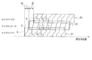
- FIG. 3 is a conceptual diagram of alignment in the circumferential direction of a captured image using a dark line according to the first embodiment of the present invention.
- FIG. 3 is a conceptual diagram of synthesis of captured images by pattern matching according to the first embodiment of the present invention.
- FIG. 5 is a processing diagram of image composition according to the first embodiment of the present invention.
- FIG. 5 is a processing diagram of image composition according to the first embodiment of the present invention.
- FIG. 10 is a conceptual diagram of synthesis of captured images by pattern matching according to the second embodiment of the present invention.
- inspects the conventional tire inner surface The layout of the conventional camera and laser light generator.
- the image composition conceptual diagram of the image imaged for every conventional area
- FIG. 1 is a block diagram showing an embodiment in which the tire inspection apparatus of the present invention is applied to the inspection of the tire inner surface Ts of the peripheral surface of the inspected tire, and FIG. 2 is replaced with a block diagram in FIG. It is an enlarged view of the inspected apparatus. 1 and 2, the same components as those in FIG. 14 are denoted by the same reference numerals.
- the tire T to be inspected is placed sideways so that the center axis of the rotary table 53 that rotates in the direction of arrow G by the drive of the motor 52 coincides with the center of the tire T. Is done.
- laser light generators 21 to 23 as illumination means for irradiating slit light 21a to 23a to the tire inner surface Ts at the tip of a suspension member (not shown) suspended from above the tire T.
- a plurality of cameras 11 to 13 composed of CCD area cameras as image pickup means for picking up the irradiation portions irradiated with the slit lights 21a to 23a are attached and positioned.
- the tire inner surface Ts to be inspected is imaged in three parts: a tire side T1 on the lower surface, a tire center T2 on the bottom surface, and a tire side T3 on the upper surface.
- the tire side T1 is imaged by the laser light generator 21 and the camera 11
- the tire center T2 is imaged by the laser light generator 22 and the camera 12
- the tire side T3 is imaged by the laser light generator 23 and the camera 13.
- the camera 12 whose imaging direction is directed to the front surface with respect to the inner peripheral surface of the tire center T2 is used as a reference
- the camera 11 becomes a position where the imaging direction advances by an angle ⁇ in the tire rotation direction indicated by the arrow G with respect to the camera 12. Directed so that.
- the camera 13 is directed to a position where the imaging direction is delayed by an angle ⁇ in the tire rotation direction indicated by the arrow G with respect to the camera 12. That is, each of the cameras 11 to 13 is disposed relatively displaced in the circumferential direction as shown in FIG. 15, and the imaging position is in the tire width direction perpendicular to the tire inner circumferential surface. Each is set differently. Then, the slit lights 21a to 23a emitted from the laser light generators 21 to 23 are irradiated so as to correspond to the imaging directions of the cameras 11 to 13, respectively. Note that the angle ⁇ and the angle ⁇ at which the cameras 11 to 13 are relatively displaced in the circumferential direction may be appropriately determined. What is necessary is just to set so that it can.
- Imaging data captured by all the cameras 11 to 13 are sequentially output to preprocessing means 31 to 33 including computers connected to the cameras 11 to 13, and for each part (T 1, T 2, T 3) for which imaging has been completed.
- preprocessing such as filtering is performed by the preprocessing means 31-33.
- the captured images P1 to P3 for which the preprocessing has been completed are individually output to the image synthesizing means 40 of the control means 46 described later connected to the preprocessing means 31 to 33.
- the control means 46 for outputting the picked-up images P1 to P3 controls the entire examination, and is roughly constituted by the image composition means 40, the camera position storage means 44, the pass / fail judgment means 47, and the marker insertion means 49 according to the present invention. Further, a keyboard 35 as input means and a monitor 36 as display means are connected.
- the control means 46 is connected to the motor drive means 51 via the drive signal line 70 and drives the motor 52 via the drive signal line 70 to control the rotation or stop of the rotary table 53. Is output.
- the control means 46 is connected to the camera 11 and the laser light generator 21 that image the tire side T1 by the imaging signal line 71, and the camera 12 and the laser light generator 22 that images the tire center T2 by the imaging signal line 72. Connected to the camera 13 and the laser light generator 23 that image the tire side T3 by the imaging signal line 73, the imaging start signal and the imaging end signal are output via the imaging signal lines 71 to 73, respectively. That is, the control means 46 individually controls the imaging by the camera 11, the imaging by the camera 12, and the imaging by the camera 13, and the imaging is started and ended at arbitrary positions with respect to the rotating tire T. .
- FIG. 3 shows the concept of a captured image at the tire center T2.
- 1s indicates the slit width of the slit light beams 21a to 23a, and if one cycle of the tire T is imaged by this slit width 1s, Images in the circumferential direction of the inner surface Ts are continuously obtained. Therefore, if the tire T to be imaged is large, the number of times of imaging is increased, and if the tire to be imaged is small, the number of times of imaging is decreased. Further, the number of times of imaging is counted as follows. Counting is started from the start of imaging, and when the dark line D as a marker is input, the count is reset once, the counting is restarted from the insertion of the dark line D, and the number of times of imaging for one tire is counted plus one imaging time Ends.
- the count of the imaging number of the camera in which the abnormality has occurred is reset once and recounted, and a dark line D reinsertion signal is sent to the marker insertion means 49 described later. Output.
- the dark line D is inserted again into all the captured images, so that re-counting is performed. That is, by continuously capturing the number of times of imaging for one rotation of the tire plus the number of times of imaging for the tire, a captured image for one rotation of the tire is obtained.
- the control unit 46 receives a notification signal such as the end of the preprocessing, and the control unit 46 and the preprocessing unit 31 are connected by a notification signal line 81.
- the control means 46 and the preprocessing means 32 are connected by a notification signal line 82, and the control means 46 and the preprocessing means 33 are connected by a notification signal line 83.
- the marker insertion means 49 is connected to the laser light generators 21 to 23 by a marker insertion line 74, and when the notification signals during imaging are output from all the preprocessing means 31 to 33 to the control means 46, the slit light is emitted. Control is performed so that the luminance of 21a to 23a is changed by one image pickup. Specifically, a marker insertion signal is simultaneously output to the laser light generators 21 to 23 via the marker insertion line 74, and the slit lights 21a to 23a are controlled to be turned off for one imaging, and the cameras 11 to 13 are controlled. A dark line D as a marker is inserted into the image to be captured.
- the camera position storage means 44 stores the amount of relative positional deviation in the circumferential direction of the imaging direction of each camera 11 to 13 as an angle.
- the amount of deviation between the camera 11 and the camera 12 is stored.
- the angle ⁇ and the shift amount between the camera 12 and the camera 13 are stored as the angle ⁇ .
- the image composition unit 40 includes a marker detection unit 48, a circumferential position alignment unit 41A, an overlapping part composition unit 42, and a processing unit 43.
- the marker detection unit 48 detects the position of the dark line D from the captured images P1 to P3 input from the preprocessing units 31 to 33.
- the circumferential position alignment means 41A reads the circumferential displacement angles ⁇ and ⁇ generated by the arrangement of the cameras 11 to 13 from the camera position storage means 44, and obtains each of the captured images P1 to P3 detected by the marker detection means 48.
- the dark lines D of the captured images P1 to P3 are displaced so as to match the angles ⁇ and ⁇ , respectively, so that the cameras 11 to 13 are aligned at the same time.
- the overlapping portion synthesizing unit 42 detects the convex portion 15 from the captured images P1 to P3 aligned by the circumferential position alignment unit 41A, and uses the convex portion 15 to perform pattern matching to synthesize the captured images P1 to P3. .
- the processing unit 43 processes the image pattern-matched by the overlapping portion combining unit 42 as a combined image PP so as to be a captured image for one round of the tire.
- This composite image PP is output to the pass / fail judgment means 47.
- the pass / fail judgment means 47 performs image processing on the unevenness from the composite image PP, so that molding defects and scratches generated on the tire inner surface Ts when the tire T is vulcanized and molded. The presence or absence of is determined. Details of the image composition by the image composition means 40 will be described later.
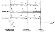
- FIG. 4 shows time-series processing of imaging and preprocessing for inspection of the tire inner surface, and the inspection process of the tire inner surface Ts having the above-described configuration will be described with reference to FIG.
- A2 indicates the imaging time for the number of times of imaging for one round of the tire + 1 imaging times.
- the person in charge of the inspection places the cameras 11 to 13 and the laser light generators 21 to 23 at predetermined positions on the inner diameter portion of the tire T, for example, the imaging center of the camera 12 is positioned substantially at the center in the width direction of the tire T.
- the control means 46 may control the up and down of the suspension member (not shown) so that it is automatically positioned at a predetermined position according to the size of the tire T input from the keyboard 35.
- an inspection start signal is input to the control means 46.
- the first tire T for the first inspection is rotated and imaging is started by the cameras 11-13. Since the imaging in this case is the first inspection for the first time, the imaging of each part of the tire side T1, the tire center T2, and the tire side T3 is started simultaneously.
- the control means 46 starts counting the number of times of imaging for each of the cameras 11 to 13 individually. During imaging, the slit light 21a to 23a is continuously applied to the rotating tire inner surface Ts.
- Image data captured by the cameras 11 to 13 are sequentially output to the preprocessing units 31 to 33.
- Signals are output from the preprocessing means 31 to 33 to the control means 46 individually.
- the marker insertion unit 49 of the control unit 46 causes the slit light beams 21a to 23a.
- a marker insertion signal is output to the laser light generators 21 to 23 so that is turned off simultaneously for one image pickup.
- the images captured by the cameras 11 to 13 are captured as a dark marker at the same time, that is, as a dark line D.
- the control means 46 resets the counted number of times of imaging of the cameras 11 to 13 once, and again starts counting the number of times of imaging for each of the cameras 11 to 13.
- the imaging data for the imaging time F1 captured between time t0 and time t1 is overwritten by the imaging data captured after insertion of the dark line D.
- the preprocessing means 31 to 33 start the processing operation (preprocessing) of the imaging data.
- the second tire T to be inspected next is placed on the rotary table 53 and waits until imaging starts.
- the preprocessing unit 31 outputs a preprocessing end notification signal to the control unit 46, and the control unit 46 rotates the second tire T on the basis of the notification signal and starts imaging the second tire side T1 by the camera 11 to start counting the number of imaging.
- the preprocessing unit 31 outputs a notification signal to the control unit 46 that the camera 11 is imaging.
- the preprocessing unit 33 outputs a preprocessing end notification signal to the control unit 46, and the control is performed.
- the means 46 starts imaging of the second tire side T3 by the camera 13 from an arbitrary position of the rotating tire T, and starts counting the number of imaging.
- the preprocessing unit 31 outputs a notification signal to the control unit 46 that the camera 11 is imaging.
- the preprocessing unit 32 outputs a preprocessing end notification signal to the control unit 46.
- the control means 46 starts imaging of the second tire center T2 by the camera 12 from an arbitrary position of the rotating tire T, and starts counting the number of imaging.
- the preprocessing unit 31 outputs a notification signal to the control unit 46 that the camera 12 is imaging.
- the notification signal of the preprocessing means 32 is input to the control means 46, the control means 46 is notified that the second tire T has been imaged by all the cameras 11-13.
- the marker insertion means 49 of the control means 46 outputs a marker insertion signal to the laser light generators 21 to 23 so that the slit lights 21a to 23a are simultaneously turned off for one imaging. To do.
- dark lines D as markers are imaged at the same time in the images captured by the cameras 11 to 13.
- the control means 46 resets the counted number of times of imaging of the camera 11 and the camera 13 once and starts counting the number of times of imaging of the camera 11 and the camera 13 again.
- the imaging data for the imaging time F2 captured by the camera 11 between the time t4 and the time t5 is overwritten by the imaging data captured after the insertion of the dark line D, and the camera 13 between the time t5 and the time t6.
- the imaging data for the imaging time F4 captured by the camera 12 is overwritten by the imaging data captured after insertion of the dark line D, and the imaging data for the imaging time F3 captured by the camera 12 between time t6 and time t7 is dark line.
- Overwriting processing is performed by imaging data captured after insertion of D.
- FIG. 5 to FIG. 9 show a synthesis procedure in which the captured images P1 to P3 captured and preprocessed by the above steps are combined by the image processing means 40, and the captured images P1 to P3 to be captured by the image processing means 40 are shown using FIG. A synthesis procedure of P3 will be described.
- the preprocessed captured images P1 to P3 are input to the marker detection unit 48 of the image processing unit 40, and the marker detection unit 48 inserts a dark line D from the captured images P1 to P3. Detect position.
- the circumferential direction alignment unit 41A reads the circumferential position shift angles ⁇ and ⁇ from the camera position storage unit 44 as shown in FIG.
- the positional deviation in the circumferential direction is aligned, and the overlapping part combining unit 42 Output.
- the overlapping portion synthesizing unit 42 uses the periodically formed convex portions 15 called ridges included in the overlapping portions Q1 and Q2 of the captured images P1 to P3 to use the captured image P1. Then, pattern matching of the captured image P2 and the captured image P2 and the captured image P3 is performed, and the overlapping portions Q1 and Q2 are synthesized.
- the processing unit 43 deletes the dark line D from the image synthesized by the overlapping portion synthesis unit 42, and then aligns one end of each image.
- the image of the portion of the tire center T2 and the tire side T1 that protrudes beyond the tire side T3 is moved to the other end side so as to be processed into a composite image PP for one tire.
- the composite image PP processed by the processing unit 43 is output to the quality determination unit 47 and the like, and the presence or absence of defects such as scratches and molding unevenness generated on the tire inner surface Ts due to the molding of the tire T is determined from the unevenness.
- the quality of molding failure is displayed on the monitor as a determination result together with the synthesized image PP synthesized on the monitor 36 as the display means.
- the positional deviation in the circumferential direction of the cameras 11 to 13 is aligned with reference to the dark line D as a marker inserted in the images captured by the cameras 11 to 13 at the same timing.
- the accuracy of the synthesis of the captured image is improved.
- Embodiment 2 In the first embodiment, after insertion of the dark line D as a marker by the marker insertion means 49, the number of times of imaging of the cameras 11 to 13 is reset and the number of times of imaging is counted again.
- the tire T The rotation may be set to stop.
- the marker insertion means 49 is connected to the laser light generators 21 to 23 by the marker insertion line 74, and is connected to the motor driving means 51 by the temporary stop signal line, so that the laser light generators 21 to 23 are connected. What is necessary is just to comprise so that rotation of the tire T may temporarily stop only for 1 imaging time, when the dark line D is inserted.
- the imaging by each of the cameras 11 to 13 need only be the number of times of imaging + 1 times the number of times of imaging for one turn of the tire after the imaging is started once.
- the number of times of imaging in this embodiment is counted as follows. If there is no abnormality in imaging, the count ends when the count from the start of imaging is the number of times of imaging for one lap of the tire + the number of times of imaging.
- the number of imaging times of the camera in which the abnormality has occurred is reset once and recounted, and a dark line D reinsertion signal is output to the marker insertion means 49 described later.
- the picked-up images P1 to P3 picked up by the cameras 11 to 13 with the above-described configuration are positioned in the circumferential direction with reference to the dark lines D inserted in the picked-up images P1 to P3.
- the captured images P1 to P3 are pattern-matched to synthesize the captured images, and then processed so as to become a combined image PP for one round of the tire.
- A2 indicates the number of times of imaging for one round of the tire + imaging time required for imaging
- B1 to B3 indicate preprocessing times.
- the first tire T for the first time of the inspection is rotated and imaging is started by the cameras 11 to 13. Since the imaging in this case is the first inspection for the first time, the imaging of each part of the tire side T1, the tire center T2, and the tire side T3 is started simultaneously. With the start of this imaging, the control means 46 starts counting the number of times of imaging for each of the cameras 11 to 13 individually. Image data captured by the cameras 11 to 13 is sequentially output to the preprocessing units 31 to 33, and a notification signal indicating that the cameras 11 to 13 are being imaged is output from the preprocessing units 31 to 33 to the control unit 46. Is done.
- the marker insertion means 49 outputs marker insertion signals to the laser light generators 21 to 23 so that the slit lights 21a to 23a are turned off simultaneously for one image pickup based on the notification signal.
- the images captured by the cameras 11 to 13 are captured as a dark marker at the same time, that is, as a dark line D.
- the imaging of the camera 12 and the camera 13 is continued as it is.
- the control means 46 since it is necessary for the control means 46 to capture the camera 11 from the beginning, the number of imaging after the occurrence of an abnormality in imaging is counted so that the number of imaging for one round of the tire + 1 imaging. To do.
- the control means 46 inserts a marker so that the dark line D is again inserted into the captured images P1 to P3 by the cameras 11 to 13.
- a signal is output to the means 49, the marker insertion means 49 outputs a marker insertion signal to the laser light generators 21 to 23, and the dark line D is inserted into all images of the cameras 11 to 13.
- the number of times of imaging of the camera 12 and the camera 13 is counted so that the number of imaging after the dark line D is inserted at the time t1 becomes the imaging number of one rotation of the tire + 1 imaging. Correction to the count.
- the imaging data of the imaging time F5 from the time t0 to the time t1 by the camera 12 and the camera 13 are overwritten by the imaging data captured after the second insertion of the dark line D.
- preprocessing of the imaging data is performed by the preprocessing means 32 and 33, respectively.
- the preprocessing means 33 outputs a preprocessing end notification signal to the control means 46, and the control means 46 rotates the second tire T on the basis of the notification signal and starts imaging the second tire side T3 by the camera 13 to start counting the number of imaging.
- the preprocessing unit 33 outputs a notification signal to the control unit 46 that the camera 13 is imaging.
- the preprocessing unit 31 when the preprocessing of the first tire side T1 by the preprocessing unit 31 is completed at the preprocessing time B1, the preprocessing unit 31 outputs a preprocessing end notification signal to the control unit 46, and the control unit 46 rotates.
- the imaging of the second tire side T1 by the camera 11 is started from an arbitrary position of the tire T to be started, and counting of the number of imaging is started.
- the preprocessing unit 31 outputs a notification signal to the control unit 46 that the camera 11 is imaging.
- the preprocessing unit 32 outputs a preprocessing end notification signal to the control unit 46, and the control unit 46 Then, imaging of the second tire center T2 by the camera 12 is started from an arbitrary position of the rotating tire T, and counting of the number of imaging is started.
- the preprocessing unit 31 outputs a notification signal to the control unit 46 that the camera 12 is imaging.
- the notification signal of the preprocessing means 32 is input to the control means 46, the control means 46 is notified that the second tire T has been imaged by all the cameras 11-13.
- the marker insertion means 49 outputs marker insertion signals to the laser light generators 21 to 23 so that the slit lights 21a to 23a are simultaneously turned off for one image pickup based on the notification signal.
- dark lines D as markers are imaged at the same time in the images captured by the cameras 11 to 13.
- the inspection of the tire T that is continuously conveyed can be efficiently performed by performing the inspection by sequentially repeating the above steps.
- the standby times C1 and C2 that have conventionally been in the cameras 11 and 13 for imaging the tire sides T1 and T3 are eliminated, and a time difference is generated in the time when the preprocessing starts or ends. Since the output timing of the preprocessed captured images of the tire side T1, T3 and tire center T2 is gradually shifted, the image output from the preprocessing means 31 to 33 to the control means 46 is transferred. Collisions can be avoided and images can be transferred smoothly. Further, as in the first embodiment, since the captured images are aligned with respect to the dark line D as the marker, accurate alignment can be performed.
- the dark lines D as the markers are inserted into the captured images captured by the cameras 11 to 13 at the same time. Since the imaging operation can be individually controlled, for example, imaging standby times C1 and C2 caused by a difference between different preprocessing times after imaging can be reduced. Further, when the captured images captured by all the cameras 11 to 13 are combined, relative positions in the circumferential direction between the cameras, that is, the camera 11 and the camera 12, and the camera 12 and the camera 13, based on the dark line D in the captured image. Since the positional deviations in the circumferential direction of the camera are aligned so as to match the deviation amounts ⁇ and ⁇ , the alignment accuracy of the captured images P1 to P3 is improved. In addition, the improved alignment accuracy also improves the matching accuracy when pattern-matching captured images. As a result, the combined accuracy of the captured images is improved. Can be prevented from being erroneously determined.
- the marker insertion means 49 included in the control means 46 temporarily stops the irradiation of the slit lights 21a to 23a for one image pickup, and marks the picked-up images taken by the cameras 11 to 13 as dark lines D.
- the dark line D instead of the dark line D, the brightness may be increased and the irradiation may be performed so that it is sufficiently brighter than the other imaged portions.
- synchronized markers are inserted into the images output from the cameras 11 to 13 to the preprocessing means 31 to 33 by the processing of the preprocessing means.
- a marker as noise may be inserted into the image by adding another configuration.
- the marker may be inserted by an ultrasonic generator, an ultraviolet generator, a high pressure generator, or the like. Further, a plurality of markers may be inserted.
- the tire T which is the subject, is rotated at the same time as imaging, but the tire T is placed on the rotary table 53 and rotated at the same time so that imaging starts at an arbitrary position of the rotating tire T. It may be.
- the number of times of imaging for one tire is counted based on the slit width s1 of the slit light. However, the number of pixels of the camera is used to obtain the length for one tire. You may make it acquire the frequency
- the tire inner surface inspection has been described above. However, the tire outer surface inspection may be performed, and the method of the present invention may be applied to a case where images captured by a plurality of cameras are combined in another inspection. According to the present invention, it is possible to accurately synthesize the alignment of images and to operate a camera as a plurality of imaging means individually, so that inspection can be performed efficiently.
Landscapes
- Physics & Mathematics (AREA)
- General Physics & Mathematics (AREA)
- Engineering & Computer Science (AREA)
- Computer Vision & Pattern Recognition (AREA)
- Length Measuring Devices By Optical Means (AREA)
- Investigating Materials By The Use Of Optical Means Adapted For Particular Applications (AREA)
- Tires In General (AREA)
Abstract
Description
従来、タイヤ内面Tsは、図14に示すようなタイヤ検査装置により成型不良などが詳細に検査される。検査は、周方向に回転するタイヤTの内径部分に撮像手段としてのカメラ11~13とタイヤ内面Tsにスリット光21a~23aを照射する照明手段としてのレーザー光発生器21~23とを位置させて、スリット光21a~23aが照射されるタイヤ内面Tsの光照射部をカメラ11~13で撮像することにより行われる。
各カメラ11~13には、カメラ毎にレーザー光発生器21~23が設けられ、レーザー光発生器21~23は上記撮像指向性に対応するようにスリット光21a~23aを照射する。具体的には、レーザー光発生器21の照射するスリット光21aは一方のタイヤサイドT1に、レーザー光発生器22の照射するスリット光22aはタイヤセンターT2に、レーザー光発生器23の照射するスリット光23aは他方のタイヤサイドT3にそれぞれタイヤ径方向に向けて照射するように設定される。このタイヤ内面Tsに照射されたスリット光21a~23aの各照射部を各カメラ11~13で撮像することにより、タイヤ内面Tsの傷、成型むらなどの凹凸形状が撮像される。
各カメラ11~13の撮像する撮像データは、カメラ毎に接続される例えばコンピュータからなる前処理手段31~33に出力され、前処理手段31~33ではタイヤ1周分以上の撮像が終了したときに撮像データの処理動作としての前処理を行い、この前処理により部位毎の撮像画像P1~P3が得られる。得られた撮像画像P1~P3は、前処理が終了する毎に前処理手段31~33と個別に接続されるコンピュータからなる制御手段46に出力される。
キーボード35には、検査するタイヤTのサイズなどの情報やカメラ11~13の配置による位置ずれ量の角度α,βが入力される。
また、モニタ36には、後述の制御手段46の画像合成手段40により合成された画像や良否判定手段47により判定されたタイヤTの良否などの判定結果が表示される。
制御手段46は、モータ52の駆動を制御するモータ駆動手段51と駆動信号線70により接続され、モータ52の駆動により回転する回転テーブル53の回転又は停止の制御をする。さらに、制御手段46は、撮像信号線71によりタイヤサイドT1を撮像するカメラ11及びレーザー光発生器21と接続され、撮像信号線72によりタイヤセンターT2を撮像するカメラ12及びレーザー光発生器22と接続され、撮像信号線73によりタイヤサイドT3を撮像するカメラ13及びレーザー光発生器23と接続され、各撮像信号線71~73を介して撮像を開始させる撮像開始信号や撮像を終了させる撮像終了信号が出力される。
周方向位置合わせ手段41は、カメラ11~13の配置によって生じる周方向の位置ずれした角度α,βをカメラ位置記憶手段44から読み出して、読み出した角度α,βの位置ずれ量と見合うように各撮像画像の撮像開始位置S1~S3を位置ずれさせて、カメラ11~13が同時に撮像を開始したかのように位置合わせする。
重なり部分合成手段42は、周方向位置合わせ手段41によって位置合わせされた撮像画像から隣接する撮像画像の重なり部分からリッジと呼ばれる凸部15を検出してパターンマッチングさせることで各撮像画像が重ね合わされる。なお、リッジとは、タイヤTを加硫成型するときにタイヤ内面Tsを押圧するブラダーの表面に周期的に形成された空気抜き用の凹溝で、この凹溝が成型によりタイヤ内面Tsに転写されて周期的な凸部15として形成されたものである。
加工処理手段43は、重なり部分合成手段42によりパターンマッチングされた画像をタイヤ1周分の合成画像PPとして加工処理した後に、良否判定手段47に出力する。
良否判定手段47では、加工処理手段43によって合成された合成画像PPからタイヤ内面Tsの凹凸について画像処理をすることでタイヤ内面Tsの加硫成型における成型不良やキズの有無を判定する。
検査初回の1本目のタイヤが、まず時刻t0において、制御手段46の出力する回転開始信号により回転テーブル53がタイヤTとともに回転すると同時に、撮像開始信号が出力されてレーザー光照射器21~23からスリット光21a~23aがタイヤサイドT1,T3、タイヤセンターT2にそれぞれ照射され、これら照射部を全カメラ11~13が同時に撮像を開始する。但し、カメラ12を基準とすれば、カメラ11はカメラ12の撮像位置よりもタイヤ回転方向Gに対して角度α進んだ位置(位相差分)から撮像され、カメラ13はカメラ12の撮像位置よりもタイヤ回転方向Gに対して角度β遅れた位置(位相差分)から撮像される。各カメラ11~13によって撮像される撮像データは、逐次、前処理手段31~33に出力される。
時刻t0で、撮像が開始されてからタイヤ1周分以上となる所定の撮像時間A1が経過した時刻t1において、制御手段46はモータ駆動手段51にタイヤTの回転を終了させる回転停止信号と、全カメラ11~13と全レーザー光照射器21~23に撮像を終了させる撮像終了信号を出力する。全カメラ11~13による撮像が終了すると、前処理手段31~33では撮像データの処理動作としての前処理が直ちに開始される。
全カメラ11~13による撮像が終了したことと前処理手段31~33による前処理の動作中の時間を利用して、時刻t2で回転テーブル53上の1本目のタイヤTを次に検査する2本目のタイヤTに載せ替え、直ちに撮像を開始できるようにカメラ11~13とレーザー光照射器21~23をタイヤ内径部の所定の位置に位置させて準備がなされる。
その後、時刻t3において、前処理時間B1で1本目のタイヤサイドT1の前処理が終了し、次に、時刻t4において前処理時間B3でタイヤサイドT3の前処理が終了し、最後に、時刻t5において前処理時間B2でタイヤセンターT2の前処理が終了して、1本目のタイヤTの前処理がすべて終了すると、制御手段46は、2本目のタイヤTの回転とともに全カメラ11~13が同時に撮像を開始するように制御する。時刻t5で、撮像が開始されてからタイヤ1周分以上となる所定の撮像時間A1が経過した時刻t6において、制御手段46はモータ駆動手段51にタイヤTの回転を終了させる回転停止信号と、全カメラ11~13と全レーザー光照射器21~23に撮像を終了させる撮像終了信号を出力する。全カメラ11~13による撮像が終了すると、前処理手段31~33では撮像データの処理動作としての前処理が直ちに開始される。
全カメラ11~13による撮像が終了したことと前処理手段31~33による前処理の動作中の時間を利用して、時刻t7で回転テーブル53上の1本目のタイヤTを次に検査する2本目のタイヤTに載せ替え、直ちに撮像を開始できるようにカメラ11~13とレーザー光照射器21~23をタイヤ内径部の所定の位置に位置させて準備がなされる。
その後、前処理時間B1で1本目のタイヤサイドT1の前処理が終了し、次に、前処理時間B3でタイヤサイドT3の前処理が終了し、最後に、時刻t8において前処理時間B2でタイヤセンターT2の前処理が終了して、2本目のタイヤTの前処理がすべて終了する。上記手順を繰り返すことで順次タイヤ内面の検査が行われている。
なお、前処理時間B1,B2,B3の差は、撮像範囲の広さにより異なり、載置面側に位置するタイヤサイドT1は載置されたことによりタイヤサイドT1の撓みがなくなるため撮像する範囲が平面的になるので前処理時間B1が最も短く、次に撮像する範囲に丸みがあるタイヤサイドT3の前処理時間B3が短く、最も撮像する範囲の広いタイヤセンターT2の前処理時間B2が長くなる。
まず、図17(a),(b)に示すように、撮像画像P1~P3は、周方向位置合わせ手段41により、各撮像画像P1~P3の撮像開始位置S1~S3をカメラ11~13の撮像方向の位置ずれ角度α,βに見合う位置ずれ量分(位相差分)それぞれ位置ずれさせる。具体的には、撮像画像P2の撮像開始位置S2を基準として、撮像画像P1の撮像開始位置S1を角度αに見合う量位置ずれさせ、撮像画像P3の撮像開始位置S3を角度βに見合う量位置ずれさせることで、全カメラ11~13があたかも周方向の同じ位置から撮像を開始したように位置合わせする。
次に、図17(c)に示すように、重なり部分合成手段42により、各カメラ11~13が撮像した撮像画像P1~P3の重複する部分をパターンマッチングにより合成する。具体的には、撮像画像P1と撮像画像P2との重なり部分Q1をパターンマッチングさせ、撮像画像P2と撮像画像P3との重なり部分Q2をパターンマッチングさせることにより、撮像画像P1~P3が合成される。パターンマッチングは、各撮像画像P1~P3中に撮像されている周期的に形成された凸部15を各撮像画像P1~P3から認識させて凸部15同士を重ね合わせることにより行われる。
次に、図17(d)に示すように、加工処理手段43により、カメラ13の撮像開始位置S3を基準にして、合成された画像からタイヤ1周分を抽出し、残りの不要な部分を削除するようにしてタイヤ1周分のタイヤ内面Tsの撮像画像PPとして加工処理され、この加工処理された撮像画像PPを良否判定手段47が良否判定することにより、撮像画像PPとともにタイヤ内面Tsの成型の良否判定結果がモニタ36に出力されて表示される。
例えば、上記待機時間C1,C2は、約5秒から6秒程度であるが、1日に検査するタイヤの数を約8,000本として単純に計算すれば、1日当たりおよそ11時間近くが待機時間に費やされ、検査効率の向上の妨げとなっているため、効率良く撮像、処理する方法が必要とされている。
例えば、図18に示すように、1本目のタイヤTの検査において、撮像が開始されてから時刻E1において、タイヤサイドT1の撮像に異常(X印)が生じたときには、再度、時刻E1から全カメラ11~13で再撮像し直す必要があり、タイヤセンターT2とタイヤサイドT3の撮像時間H分の撮像データが無駄になっている。
しかし、特許文献1の方法によれば、あらかじめ用意されたタイヤ内面のマスター画像と複数の撮像手段によって撮像された部位ごとを比較することによりタイヤ内面の検査を行っており、検査を行うタイヤ内面のマスター画像を用意する必要があり手間がかかってしまう。また、成型されるタイヤの内面は、タイヤ毎に多少の個体差がありマスター画像との比較では個体差による正確なタイヤ内面の検査を行うことができない。
本発明によれば、マーカ挿入手段が全撮像手段の撮像画像中に同一時刻でマーカを入れることにより、複数の撮像手段の撮像を同時に開始しなくても、マーカを基準にしてすべての撮像画像を合成することができるので、複数の撮像手段の撮像が同時に行われる必要がなくなるので効率よく撮像して検査することが可能となる。
本発明によれば、撮像動作後の撮像データ処理動作が終了したものから順次撮像が開始されるので、連続的に撮像できるので効率よく検査をすることができる。
本発明によれば、各撮像手段が同時に撮像しなくてもよいので、複数の撮像手段のうち撮像が終了していない撮像手段の撮像終了を待つことなく撮像できるので、効率よく撮像手段が撮像することができる。
本発明によれば、全撮像手段による撮像動作後に直ちに被検査タイヤを交換できるので撮像データ処理動作が終了するのを待たずに被検査タイヤを交換できるので、撮像データの処理動作が終了した順に撮像手段が撮像を直ちに開始できるので効率よく検査することができる。
本発明によれば、照明手段の照明の輝度を変化させてマーカとして用いるので他の構成を必要とせず容易に制御することができる。例えば、輝度が零となるように変化させれば、明らかに撮像画像と輝度が異なるので容易にマーカの位置を検出することができる。
本発明によれば、撮像画像中に明らかに他の撮像された部分と異なる画像が挿入されるのでマーカの位置の検出が容易になる。
本発明によれば、マーカを複数本、同一時刻で挿入することにより、同じパターンのマーカが全撮像画像に挿入されるので、マーカの位置の検出が容易になる。
本発明によれば、撮像手段が必要以上の撮像をしないので、撮像にかかる時間や、撮像された撮像画像の撮像データの処理動作に要する時間が短くなる。
本発明によれば、隣接する領域を撮像する撮像手段が重なり部分を有するように撮像されることで、複数の撮像手段が撮像した撮像画像を合成するときにパターンマッチングにより合成することができるので画像の合成が容易になる。
図1は、本発明のタイヤの検査装置を被検査タイヤの周面のうちタイヤ内面Tsの検査に適用した一実施形態を示すブロック図であり、図2は、図1において、ブロック図に置き換えられた検査装置の拡大図である。なお、図1,図2において、図14と同じ構成のものには同一の符号を付した。
図1,図2に示すように、被検査対象であるタイヤTが、モータ52の駆動により矢印G方向に回転する回転テーブル53の中心軸とタイヤTの中心が一致するように横向きに載置される。このタイヤTの内径部には、タイヤTの上方より垂設された図外の吊設部材の先端にタイヤ内面Tsにスリット光21a~23aを照射する照明手段としてのレーザー光発生器21~23と、スリット光21a~23aが照射される照射部を撮像する撮像手段としてのCCDエリアカメラからなる複数のカメラ11~13が取り付けられて位置される。
例えば、タイヤセンターT2の内周面に対して撮像方向が正面に向くカメラ12を基準にすれば、カメラ11はカメラ12に対して矢印Gのタイヤ回転方向に撮像方向が角度α進む位置となるように向けられる。また、カメラ13はカメラ12に対して矢印Gのタイヤ回転方向に撮像方向が角度β遅れる位置に向けられる。つまり、各カメラ11~13は、図15に示したように周方向に相対的に位置ずれして配置され、かつ、互いにタイヤ内周面に対し直角方向であるタイヤの幅方向に撮像位置がそれぞれ異なるように設定される。そして、各カメラ11~13の撮像する方向に対応するようにレーザー光発生器21~23の照射するスリット光21a~23aが照射される。
なお、カメラ11~13が周方向に相対的に位置ずれして配置される角度αや角度βは、適宜決めればよく、例えば、タイヤTの内径部に位置でき、かつ、タイヤ内面Tsが撮像できるように設定されればよい。
また、制御手段46は、撮像信号線71によりタイヤサイドT1を撮像するカメラ11及びレーザー光発生器21と接続され、撮像信号線72によりタイヤセンターT2を撮像するカメラ12及びレーザー光発生器22と接続され、撮像信号線73によりタイヤサイドT3を撮像するカメラ13及びレーザー光発生器23と接続されて、各撮像信号線71~73を介して撮像開始信号や撮像終了信号を出力する。
つまり、制御手段46は、カメラ11による撮像と、カメラ12による撮像と、カメラ13による撮像とを個別に制御し、回転するタイヤTに対して任意の位置でそれぞれ撮像の開始や終了がなされる。
ここで、撮像回数について説明する。図3はタイヤセンターT2における撮像画像の概念を示し、同図において、1sは、スリット光21a~23aのスリット幅を示し、このスリット幅1s分でタイヤTの1周分を撮像すれば、タイヤ内面Tsの周方向の画像が連続的に得られる。よって、撮像するタイヤTが大きなものであれば、撮像回数は多くなり、撮像するタイヤが小さいものであれば、撮像回数は少なくなる。
また、撮像回数のカウントは、次のようになされる。撮像の開始からカウントの開始を行い、マーカとしての暗線Dが入力されるとカウントを一度リセットして、暗線Dの挿入から再カウントを行いタイヤ1周分の撮像回数に1撮像回プラスでカウントが終了する。また、例えば、撮像に異常が生じた場合には、異常の生じたカメラの撮像回数のカウントを1度リセットして改めてカウントし直すとともに、後述するマーカ挿入手段49に暗線Dの再挿入信号を出力する。これにより、再び暗線Dがすべての撮像画像に挿入されるので、再カウントが行われる。
つまり、常にタイヤ1周分の撮像回数+1撮像回分を連続的に撮像することで、タイヤ1周分の撮像画像が得られることになる。
具体的には、マーカ挿入線74を介してマーカ挿入信号をレーザー光発生器21~23に同時に出力して、スリット光21a~23aが1撮像回分消灯するように制御し、カメラ11~13の撮像する画像にマーカとしての暗線Dが挿入されるようにする。
マーカ検出手段48は、前処理手段31~33から入力される撮像画像P1~P3から暗線Dの位置を検出する。
周方向位置合わせ手段41Aは、カメラ11~13の配置により生じる周方向の位置ずれ角度α,βをカメラ位置記憶手段44から読み出して、マーカ検出手段48により検出された各撮像画像P1~P3の暗線Dを移動基準として、各撮像画像P1~P3の暗線Dを角度α,βと見合うようにそれぞれ位置ずれさせることで、カメラ11~13が同時に撮像を開始したかのように位置合わせする。
重なり部分合成手段42は、周方向位置合わせ手段41Aによって位置合わせされた撮像画像P1~P3から凸部15を検出し、この凸部15を用いてパターンマッチングさせて撮像画像P1~P3を合成する。
加工処理手段43は、重なり部分合成手段42によってパターンマッチングされた画像をタイヤ1周分の撮像画像となるように合成画像PPとして加工処理する。この合成画像PPは、良否判定手段47に出力され、良否判定手段47では合成画像PPから凹凸を画像処理することにより、タイヤTを加硫成型するときにタイヤ内面Tsに生じた成型不良やキズの有無が判定される。なお画像合成手段40による画像の合成の詳細については後述する。
まず、検査の前準備として検査担当者によって検査初回である1本目の被検査対象となるタイヤTが回転テーブル53に載置され、このタイヤTの寸法などの情報とカメラ11~13の相対的位置ずれ量としての角度α,βがキーボード35から入力される。これにより、制御手段46では、タイヤTのサイズに見合った撮像回数が算出される。
図4において、検査開始信号の入力に基づき、時刻t0において、検査初回の1本目のタイヤTが回転するとともにカメラ11~13により撮像が開始される。この場合の撮像は検査初回の1本目の検査であるので、タイヤサイドT1,タイヤセンターT2,タイヤサイドT3のそれぞれの部位の撮像が同時に開始される。この撮像の開始により、制御手段46は、各カメラ11~13毎の撮像回数を個別にカウントを開始する。なお、撮像中は、回転するタイヤ内面Tsに対して連続的にスリット光21a~23aが照射される。
各カメラ11~13によって撮像される撮像データは、逐次、前処理手段31~33に出力され、この撮像データが前処理手段31~33に入力されるとカメラ11~13が撮像中との報知信号が前処理手段31~33から個別に制御手段46に出力される。
暗線Dが挿入されると制御手段46では、カウントしてきたカメラ11~13の撮像回数を1度リセットして、再びカメラ11~13毎の撮像回数のカウントを改めて開始する。
このとき、時刻t0~時刻t1の間で撮像された撮像時間F1分の撮像データは、暗線Dの挿入後に撮像された撮像データによって上書き処理されるようになっている。
そして、時刻t4において、前処理手段31による1本目のタイヤサイドT1の前処理が前処理時間B1で終了すると、前処理手段31は前処理終了の報知信号を制御手段46に出力し、制御手段46はこの報知信号に基づき2本目のタイヤTを回転させるとともにカメラ11による2本目のタイヤサイドT1の撮像を開始させて、撮像回数のカウントを開始する。カメラ11の撮像が開始されて撮像データが前処理手段31に出力されると、前処理手段31は制御手段46にカメラ11が撮像中であることの報知信号を出力する。
暗線Dが挿入されると制御手段46では、カウントしてきたカメラ11とカメラ13の撮像回数を1度リセットして、再びカメラ11とカメラ13の撮像回数のカウントを改めて開始する。
このとき、時刻t4~時刻t5の間でカメラ11が撮像した撮像時間F2分の撮像データは、暗線Dの挿入後に撮像された撮像データによって上書き処理され、時刻t5~時刻t6の間でカメラ13が撮像した撮像時間F4分の撮像データは、暗線Dの挿入後に撮像された撮像データによって上書き処理され、時刻t6~時刻t7の間でカメラ12が撮像した撮像時間F3分の撮像データは、暗線Dの挿入後に撮像された撮像データによって上書き処理される。
上記工程を繰り返すことにより、順次タイヤTの内面検査が行われる。
まず、図5に示すように、前処理された撮像画像P1~P3は、画像処理手段40のマーカ検出手段48に入力され、マーカ検出手段48では、撮像画像P1~P3から暗線Dが挿入された位置を検出する。この検出された暗線Dの位置を用いて周方向位置合わせ手段41Aでは、図6に示すように、カメラ位置記憶手段44から周方向の位置ずれ角度α,βを読み出して、撮像画像P2の暗線Dを基準として角度α,βに相当する撮像回数分、撮像画像P1及びP3の暗線Dを周方向に位置ずれさせることにより、周方向の位置ずれを位置合わせして、重なり部分合成手段42に出力する。
この加工処理手段43により加工処理された合成画像PPは、良否判定手段47などに出力されて、タイヤTの成型によってタイヤ内面Tsに生じるキズや成型むらなどの不良の有無が凹凸から判定され、表示手段としてのモニタ36に合成された合成画像PPとともに成型の不良の良否が判定結果としてモニタ上に表示される。
実施形態1では、マーカ挿入手段49によるマーカとしての暗線Dの挿入後に、カメラ11~13の撮像回数をリセットして再度撮像回数をカウントし直すようにしたが、暗線Dの挿入時に、タイヤTの回転を停止するように設定してもよい。
具体的には、マーカ挿入手段49が、レーザー光発生器21~23とマーカ挿入線74により接続されるとともに、モータ駆動手段51と一時停止信号線により接続し、レーザー光発生器21~23が暗線Dを挿入するときにタイヤTの回転が1撮像回分だけ一時的に停止するように構成すればよい。
この場合、各カメラ11~13による撮像は、一度撮像が開始されてから、撮像回数がタイヤ1周分の撮像回数+1撮像分だけでよい。なお、本形態での撮像回数のカウントは、次のようになされる。撮像に異常がない場合には、撮像の開始からのカウントがタイヤ1周分の撮像回数+1撮像回でカウントが終了する。また、撮像に異常が生じた場合には、異常の生じたカメラの撮像回数のカウントを1度リセットして改めてカウントし直すとともに、後述するマーカ挿入手段49に暗線Dの再挿入信号を出力する。これにより、撮像に異常のないカメラの撮像画像には、一度の撮像中に2本以上の暗線Dが挿入されるので、最後に挿入された暗線Dの一つ前に挿入された暗線Dからの撮像回数を有効とし、例えば、最後に挿入された暗線Dの一つ前に挿入された暗線Dからの撮像回数がタイヤ1周分の撮像回数+1撮像回分に達したときに撮像が終了する。
その後、例えば、暗線Dが挿入された時刻t1よりも後の、時刻E1において、カメラ11の撮像に異常が発生した場合、本形態ではカメラ12とカメラ13の撮像はそのまま継続される。この場合、制御手段46はカメラ11の撮像については、始めから撮像する必要があるので、撮像に異常が発生したとき以降の撮像回数がタイヤ1周分の撮像回数+1撮像分となるようにカウントする。
これにより、カメラ12とカメラ13が時刻t0~時刻t1まで撮像時間F5分の撮像データは、2回目の暗線Dの挿入後に撮像された撮像データによって上書き処理される。そして、カメラ12,13の撮像回数がタイヤ1周分+1撮像分に達すると、それぞれ前処理手段32,33により撮像データの前処理が行われる。
次に、時刻t4では、全カメラ11~13による撮像動作が終了しているので、次に検査を行う2本目のタイヤTを回転テーブル53上に載せ替えて撮像開始まで待機する。
次に、前処理手段31による1本目のタイヤサイドT1の前処理が前処理時間B1で終了すると、前処理手段31は前処理終了の報知信号を制御手段46に出力し、制御手段46は回転するタイヤTの任意の位置からカメラ11による2本目のタイヤサイドT1の撮像を開始させて、撮像回数のカウントを開始する。カメラ11の撮像が開始されて撮像データが前処理手段31に出力されると、前処理手段31は制御手段46にカメラ11が撮像中であることの報知信号を出力する。
次に、前処理手段32による1本目のタイヤセンターT2の前処理が前処理時間B2で終了すると、前処理手段32は、前処理終了の報知信号を制御手段46に出力し、制御手段46は、回転するタイヤTの任意の位置からカメラ12による2本目のタイヤセンターT2の撮像を開始させて、撮像回数のカウントを開始する。カメラ12の撮像が開始されて撮像データが前処理手段32に出力されると、前処理手段31は制御手段46にカメラ12が撮像中であることの報知信号を出力する。この前処理手段32の報知信号が制御手段46に入力されたことにより、2本目のタイヤTが全カメラ11~13により撮像が開始されていることが、制御手段46に報知される。
上記工程を順次繰り返して検査が行われることにより連続的に搬送されるタイヤTの検査を効率良く行うことができる。
また、全カメラ11~13が撮像した各撮像画像を合成するときに、撮像画像中の暗線Dを基準にカメラ間、つまりカメラ11とカメラ12、カメラ12とカメラ13の周方向の相対的位置ずれ量の角度α,βに見合うようにカメラの周方向の位置ずれを位置合わせするので撮像画像P1~P3の位置合わせ精度が向上する。さらに、位置合わせ精度が向上したことにより、撮像画像同士をパターンマッチングするときのマッチング精度も向上するため、結果として合成される撮像画像の合成精度が向上するので、画像合成に起因する良品を不良と誤判定することが防止できる。
また、実際にスリット光21a~23aの輝度を変化させるのではなく、カメラ11~13が前処理手段31~33に出力する画像に、前処理手段の処理によって、同期されたマーカが挿入されるように構成してもよく、さらに、他の構成を追加することにより画像にノイズとしてのマーカが挿入されるようにしてもよい。具体的には、超音波発生器や紫外線発生器、高圧発生器などによってマーカが挿入されるようにしてもよい。さらに、マーカは複数本挿入してもよい。
また、撮像と同時に被検体であるタイヤTを回転するようにしたが、回転テーブル53にタイヤTを載せ替えると同時に回転させておき、回転するタイヤTの任意の位置で撮像が開始されるようにしてもよい。
また、上記検査の撮像において、スリット光のスリット幅s1を基準としてタイヤ1周分の撮像回数をカウントするとして説明したが、カメラの画素数を用いてタイヤ1周分の長さを求めて撮像回数を得るようにしてもよい。
21a;22a;23a スリット光、31;32;33 前処理手段、
40 画像処理手段、41;41A 周方向位置合わせ手段、
42 重なり部分合成手段、43 加工処理手段、
44 カメラ位置記憶手段、46 制御手段、47 良否判定手段、
48 マーカ検出手段、49 マーカ挿入手段、51 モータ駆動手段、
D 暗線、P1~P3 画像、T タイヤ、T1;T3 タイヤサイド、
T2 タイヤセンター、Ts タイヤ内面。
Claims (9)
- 被検査タイヤの周面を撮像するように周方向に相対的に位置ずれして配置され、かつ互いに前記被検査タイヤの幅方向に撮像位置がそれぞれ異なるように設定された複数の撮像手段を備え、前記撮像手段により得られる各撮像画像を合成するタイヤの検査装置において、
前記タイヤが複数の撮像手段と相対的に周方向に回転されて、撮像動作が全撮像手段で行われるときに、全撮像手段の撮像画像中に同一時刻でマーカを入れるマーカ挿入手段を備え、全撮像手段の各撮像画像を合成するときに、このマーカが撮像手段間の周方向の相対的位置ずれ量に見合ってずれるように合成されることを特徴とするタイヤの検査装置。 - 各撮像手段の撮像動作は、撮像動作後の撮像データ処理動作が終了したものから順次開始されることを特徴とする請求項1に記載のタイヤの検査装置。
- 各撮像手段の撮像動作は、各撮像手段毎にそれぞれ異なるタイミングで開始されることを特徴とする請求項1又は請求項2に記載のタイヤの検査装置。
- 被検査タイヤの交換を全撮像手段による撮像動作終了後に行うようにしたことを特徴とする請求項1乃至請求項3いずれかに記載のタイヤの検査装置。
- マーカ挿入手段は、各撮像手段の撮像位置を照明する照明手段の輝度を変化させるものからなることを特徴とする請求項1乃至請求項4いずれかに記載のタイヤの検査装置。
- マーカ挿入手段は、各撮像手段の撮像画像中にノイズを発生させるものからなることを特徴とする請求項1乃至請求項4いずれかに記載のタイヤの検査装置。
- 前記マーカ挿入手段により挿入されるマーカは、複数本からなることを特徴とする請求項1乃至請求項6いずれかに記載のタイヤの検査装置。
- 前記撮像手段は、前記タイヤの周面の1周分の撮像と前記マーカの挿入分の撮像のみを行うことを特徴とする請求項1乃至請求項7いずれかに記載のタイヤの検査装置。
- 前記タイヤの検査装置は、前記複数の撮像手段がタイヤ周面の異なる領域をそれぞれ撮像するように設定され、かつ、隣接する領域を撮像する撮像手段同士が撮像する領域に互いに重なり部分を有するように撮像し、撮像された画像の重なり部分をパターンマッチングさせて合成することを特徴とする請求項1乃至請求項8いずれかに記載のタイヤの検査装置。
Priority Applications (3)
| Application Number | Priority Date | Filing Date | Title |
|---|---|---|---|
| EP10774955.8A EP2431734B1 (en) | 2009-05-13 | 2010-05-13 | Tire inspection device |
| US13/320,458 US8618924B2 (en) | 2009-05-13 | 2010-05-13 | Tire inspection apparatus |
| CN201080031750.5A CN102460132B (zh) | 2009-05-13 | 2010-05-13 | 轮胎检查装置 |
Applications Claiming Priority (2)
| Application Number | Priority Date | Filing Date | Title |
|---|---|---|---|
| JP2009-116206 | 2009-05-13 | ||
| JP2009116206A JP5318657B2 (ja) | 2009-05-13 | 2009-05-13 | タイヤの検査装置 |
Publications (1)
| Publication Number | Publication Date |
|---|---|
| WO2010131698A1 true WO2010131698A1 (ja) | 2010-11-18 |
Family
ID=43085071
Family Applications (1)
| Application Number | Title | Priority Date | Filing Date |
|---|---|---|---|
| PCT/JP2010/058086 Ceased WO2010131698A1 (ja) | 2009-05-13 | 2010-05-13 | タイヤの検査装置 |
Country Status (5)
| Country | Link |
|---|---|
| US (1) | US8618924B2 (ja) |
| EP (1) | EP2431734B1 (ja) |
| JP (1) | JP5318657B2 (ja) |
| CN (1) | CN102460132B (ja) |
| WO (1) | WO2010131698A1 (ja) |
Cited By (4)
| Publication number | Priority date | Publication date | Assignee | Title |
|---|---|---|---|---|
| JP2012112836A (ja) * | 2010-11-25 | 2012-06-14 | Toyo Tire & Rubber Co Ltd | 照明装置及びタイヤの検査装置 |
| RU2497074C1 (ru) * | 2012-05-03 | 2013-10-27 | Федеральное государственное бюджетное образовательное учреждение высшего профессионального образования "Тюменский государственный нефтегазовый университет" (ТюмГНГУ) | Устройство для диагностики стенки магистральных трубопроводов муаровым методом |
| EP2799848A4 (en) * | 2011-12-28 | 2015-08-12 | Bridgestone Corp | DEVICE AND METHOD FOR EXTERNAL VIEW INSPECTION |
| EP2732236B1 (de) * | 2011-07-11 | 2020-05-13 | Beissbarth GmbH | Optische vorrichtung und verfahren zur reifenprüfung |
Families Citing this family (35)
| Publication number | Priority date | Publication date | Assignee | Title |
|---|---|---|---|---|
| JP5770486B2 (ja) | 2011-02-21 | 2015-08-26 | 株式会社トプコン | 全周画像計測装置 |
| ITMI20122194A1 (it) * | 2012-12-20 | 2014-06-21 | Pirelli | Metodo ed impianto per confezionare pneumatici |
| US11066243B2 (en) | 2013-01-11 | 2021-07-20 | Multilift, Inc. | Method and system for conveying articles and an apparatus for doing the same |
| US9260247B2 (en) | 2013-01-11 | 2016-02-16 | Multilift, Inc. | Method and system for conveying articles and an apparatus for doing the same |
| US11691818B2 (en) | 2013-01-11 | 2023-07-04 | Multilift, Inc. | Method and system for conveying articles and an apparatus for doing the same |
| US9061830B2 (en) | 2013-01-11 | 2015-06-23 | Multilift, Inc. | Method and system for conveying tires and an apparatus for doing the same |
| FR3011080B1 (fr) * | 2013-09-26 | 2017-01-20 | Michelin & Cie | Dispositif d'acquisition d'images destine a l'inspection visuelle de la surface interieure d'un pneumatique et procede associe |
| JP5775132B2 (ja) * | 2013-11-01 | 2015-09-09 | 株式会社ブリヂストン | タイヤの検査装置 |
| CN105793697B (zh) * | 2013-12-03 | 2018-10-19 | 横滨橡胶株式会社 | 轮胎检查方法及其装置 |
| JP6142923B2 (ja) * | 2014-01-10 | 2017-06-07 | 横浜ゴム株式会社 | タイヤ内部の材料貼り合わせの不良を検出する方法及び装置 |
| JP6152353B2 (ja) * | 2014-02-18 | 2017-06-21 | 株式会社神戸製鋼所 | 検査装置 |
| JP6334278B2 (ja) * | 2014-06-06 | 2018-05-30 | 株式会社ブリヂストン | 計測装置 |
| KR101563999B1 (ko) | 2014-12-19 | 2015-10-28 | 주식회사 한성시스코 | 타이어 재료의 실시간 폭 및 두께 측정 시스템 및 그 제어 방법 |
| MX378779B (es) | 2015-12-16 | 2025-03-10 | Pirelli | Método y aparato para revisar neumáticos. |
| US10670497B2 (en) | 2015-12-16 | 2020-06-02 | Pirelli Tyre S.P.A | Device and method for analysis of tyres comprising first and second image acquistion systems |
| WO2017109688A1 (en) * | 2015-12-22 | 2017-06-29 | Pirelli Tyre S.P.A. | Apparatus and method for checking tyres |
| CN108472894B (zh) * | 2015-12-28 | 2021-01-29 | 倍耐力轮胎股份公司 | 用于管理轮胎检查设备的方法和相关的轮胎检查设备 |
| US10809158B2 (en) | 2015-12-28 | 2020-10-20 | Pirelli Tyre S.P.A. | Apparatus and method for checking tyres |
| EP3397938B1 (en) | 2015-12-28 | 2019-08-28 | Pirelli Tyre S.p.A. | Apparatus for checking tyres |
| CN105681656B (zh) * | 2016-01-14 | 2020-03-03 | 上海小蚁科技有限公司 | 用于子弹时间拍摄的系统和方法 |
| CN105526884A (zh) * | 2016-01-29 | 2016-04-27 | 吉林大学 | 基于主动视觉的汽车车轮轮辋形貌旋转扫描重建系统 |
| US10425583B2 (en) | 2016-05-18 | 2019-09-24 | Hitachi Kokusai Electric Inc. | Imaging device |
| MX2018013828A (es) * | 2016-05-31 | 2019-03-28 | Pirelli | Metodo para verificar neumaticos. |
| DE202016105450U1 (de) * | 2016-08-24 | 2016-11-07 | INSISTO GmbH | Vorrichtung zur Inspektion von zumindest der Außenseiten von Kraftfahrzeugen |
| JP6755625B2 (ja) * | 2016-10-30 | 2020-09-16 | ジヤトコ株式会社 | 黒皮残りの検出方法および検出装置 |
| US10766710B2 (en) | 2018-02-16 | 2020-09-08 | Multilift, Inc. | Vehicle-mounted conveyor system |
| CN108492254B (zh) * | 2018-03-27 | 2022-09-27 | 西安优艾智合机器人科技有限公司 | 图像采集系统及方法 |
| AT521199A1 (de) * | 2018-04-20 | 2019-11-15 | Dibit Messtechnik Gmbh | Vorrichtung und verfahren zur erfassung von oberflächen |
| JP7030614B2 (ja) * | 2018-05-25 | 2022-03-07 | 株式会社ブリヂストン | タイヤ状態管理システム及びタイヤ状態管理プログラム |
| US11332321B2 (en) | 2018-06-04 | 2022-05-17 | Multilift, Inc. | Vehicle-mounted conveyor system |
| US10913381B2 (en) | 2018-06-04 | 2021-02-09 | Multilift, Inc. | Vehicle-mounted conveyor system |
| CN109100364A (zh) * | 2018-06-29 | 2018-12-28 | 杭州国翌科技有限公司 | 一种基于光谱分析的隧道病害监测系统及监测方法 |
| CN110648324A (zh) * | 2019-09-29 | 2020-01-03 | 百度在线网络技术(北京)有限公司 | 车辆爆胎预警方法、装置以及计算机设备 |
| DE102022128410B4 (de) * | 2022-10-26 | 2025-06-26 | Deutsches Zentrum für Luft- und Raumfahrt e.V. | Messvorrichtung zur Bestimmung einer Verteilung eines Wärmeträgermediums und Verfahren zur Bestimmung einer Verteilung eines Wärmeträgermediums |
| KR102857836B1 (ko) * | 2025-02-07 | 2025-09-10 | 주식회사 혜원 | 타이어 금형의 커프 블레이드 검사시스템 및 이를 이용한 타이어 금형의 커프 블레이드 검사방법 |
Citations (4)
| Publication number | Priority date | Publication date | Assignee | Title |
|---|---|---|---|---|
| JPH05264411A (ja) * | 1991-12-16 | 1993-10-12 | Bridgestone Corp | タイヤ組立中における構成要素位置の監視装置及び方法 |
| JPH07152860A (ja) | 1993-11-29 | 1995-06-16 | Toyo Tire & Rubber Co Ltd | 凹凸文字の読取り装置 |
| JP2001249012A (ja) | 1999-12-28 | 2001-09-14 | Bridgestone Corp | 被検体の外観形状検査方法及び装置 |
| JP2008185511A (ja) * | 2007-01-31 | 2008-08-14 | Bridgestone Corp | タイヤのrro計測方法とその装置 |
Family Cites Families (10)
| Publication number | Priority date | Publication date | Assignee | Title |
|---|---|---|---|---|
| EP1043578B1 (de) * | 1999-04-09 | 2004-10-13 | Steinbichler Optotechnik Gmbh | Optisches Prüfgerät für Reifen |
| DE60235578D1 (de) * | 2001-12-04 | 2010-04-15 | Bridgestone Corp | Verfahren zur reifenuntersuchung |
| DE10333802B4 (de) * | 2003-07-24 | 2005-09-08 | Steinbichler Optotechnik Gmbh | Verfahren und Vorrichtung zum Prüfen von Reifen |
| US6934018B2 (en) * | 2003-09-10 | 2005-08-23 | Shearographics, Llc | Tire inspection apparatus and method |
| US7436504B2 (en) * | 2003-09-10 | 2008-10-14 | Shear Graphics, Llc | Non-destructive testing and imaging |
| DE102004050355A1 (de) * | 2004-10-15 | 2006-04-27 | Steinbichler Optotechnik Gmbh | Verfahren und Vorrichtung zum Prüfen der Oberfläche eines Reifens |
| JP4812432B2 (ja) * | 2006-01-10 | 2011-11-09 | 株式会社ブリヂストン | タイヤ点検装置、タイヤ点検システム及びタイヤ点検方法 |
| DE102006014058B4 (de) * | 2006-03-27 | 2008-04-17 | Mähner, Bernward | Vorrichtung und Verfahren zum optischen Prüfen eines Reifens |
| EP2172737B1 (en) * | 2007-08-06 | 2013-04-24 | Kabushiki Kaisha Kobe Seiko Sho | Tire shape measuring system |
| JP5025442B2 (ja) * | 2007-12-10 | 2012-09-12 | 株式会社ブリヂストン | タイヤ形状検査方法とその装置 |
-
2009
- 2009-05-13 JP JP2009116206A patent/JP5318657B2/ja not_active Expired - Fee Related
-
2010
- 2010-05-13 CN CN201080031750.5A patent/CN102460132B/zh not_active Expired - Fee Related
- 2010-05-13 US US13/320,458 patent/US8618924B2/en not_active Expired - Fee Related
- 2010-05-13 WO PCT/JP2010/058086 patent/WO2010131698A1/ja not_active Ceased
- 2010-05-13 EP EP10774955.8A patent/EP2431734B1/en not_active Not-in-force
Patent Citations (4)
| Publication number | Priority date | Publication date | Assignee | Title |
|---|---|---|---|---|
| JPH05264411A (ja) * | 1991-12-16 | 1993-10-12 | Bridgestone Corp | タイヤ組立中における構成要素位置の監視装置及び方法 |
| JPH07152860A (ja) | 1993-11-29 | 1995-06-16 | Toyo Tire & Rubber Co Ltd | 凹凸文字の読取り装置 |
| JP2001249012A (ja) | 1999-12-28 | 2001-09-14 | Bridgestone Corp | 被検体の外観形状検査方法及び装置 |
| JP2008185511A (ja) * | 2007-01-31 | 2008-08-14 | Bridgestone Corp | タイヤのrro計測方法とその装置 |
Non-Patent Citations (1)
| Title |
|---|
| See also references of EP2431734A4 * |
Cited By (5)
| Publication number | Priority date | Publication date | Assignee | Title |
|---|---|---|---|---|
| JP2012112836A (ja) * | 2010-11-25 | 2012-06-14 | Toyo Tire & Rubber Co Ltd | 照明装置及びタイヤの検査装置 |
| EP2732236B1 (de) * | 2011-07-11 | 2020-05-13 | Beissbarth GmbH | Optische vorrichtung und verfahren zur reifenprüfung |
| EP2799848A4 (en) * | 2011-12-28 | 2015-08-12 | Bridgestone Corp | DEVICE AND METHOD FOR EXTERNAL VIEW INSPECTION |
| US9310278B2 (en) | 2011-12-28 | 2016-04-12 | Bridgestone Corporation | Appearance inspection apparatus and appearance inspection method with uneveness detecting |
| RU2497074C1 (ru) * | 2012-05-03 | 2013-10-27 | Федеральное государственное бюджетное образовательное учреждение высшего профессионального образования "Тюменский государственный нефтегазовый университет" (ТюмГНГУ) | Устройство для диагностики стенки магистральных трубопроводов муаровым методом |
Also Published As
| Publication number | Publication date |
|---|---|
| EP2431734A4 (en) | 2015-11-11 |
| EP2431734B1 (en) | 2017-07-19 |
| US20120092149A1 (en) | 2012-04-19 |
| CN102460132A (zh) | 2012-05-16 |
| CN102460132B (zh) | 2014-05-28 |
| EP2431734A1 (en) | 2012-03-21 |
| JP5318657B2 (ja) | 2013-10-16 |
| JP2010266259A (ja) | 2010-11-25 |
| US8618924B2 (en) | 2013-12-31 |
Similar Documents
| Publication | Publication Date | Title |
|---|---|---|
| JP5318657B2 (ja) | タイヤの検査装置 | |
| US9677879B2 (en) | Tire appearance inspection apparatus and method | |
| US20070237385A1 (en) | Defect inspection apparatus | |
| TWI477764B (zh) | 影像製作方法、基板檢查方法、記錄有用以執行該影像製作方法及該基板檢查方法之程式的記錄媒體與基板檢查裝置 | |
| CN110274910B (zh) | 图像检查装置、图像检查方法以及计算机可读记录介质 | |
| WO2016051841A1 (ja) | 検査装置および検査方法 | |
| JP2011107024A (ja) | 筒形圧着端子の外観検査装置 | |
| JPWO2017061318A1 (ja) | セラミックス体の表面検査方法 | |
| JP2012063268A (ja) | ワーク検査装置及びワーク検査方法 | |
| JP2011123019A (ja) | 画像検査装置 | |
| CN113518911B (zh) | 用于内孔窥视仪检查的方法和设备 | |
| JP2011059022A (ja) | タイヤ外観検査装置 | |
| CN117308822B (zh) | 焊接检测系统及使用方法、以及焊接检测方法 | |
| JP2008175818A (ja) | 表面検査装置及び方法 | |
| JPWO2009072483A1 (ja) | 観察装置および観察方法 | |
| JP2004264054A (ja) | 欠陥検査装置及びその方法 | |
| CN114222909A (zh) | 晶片外观检查装置和方法 | |
| JP2011252886A (ja) | 印刷物の検査方法及び印刷物の検査装置 | |
| JP2009192358A (ja) | 欠陥検査装置 | |
| CN107462187A (zh) | 陶瓷插芯同轴度检测时光斑圆心确定方法及装置 | |
| WO2013136416A1 (ja) | 産業用機械及びカメラユニット | |
| JP4794383B2 (ja) | ゴムホースの外観検査装置 | |
| CN223770100U (zh) | 晶圆检测系统 | |
| JP2020144076A (ja) | 検査装置及び検査方法 | |
| JP3130548B2 (ja) | 画像処理装置 |
Legal Events
| Date | Code | Title | Description |
|---|---|---|---|
| WWE | Wipo information: entry into national phase |
Ref document number: 201080031750.5 Country of ref document: CN |
|
| 121 | Ep: the epo has been informed by wipo that ep was designated in this application |
Ref document number: 10774955 Country of ref document: EP Kind code of ref document: A1 |
|
| NENP | Non-entry into the national phase |
Ref country code: DE |
|
| WWE | Wipo information: entry into national phase |
Ref document number: 8841/DELNP/2011 Country of ref document: IN |
|
| WWE | Wipo information: entry into national phase |
Ref document number: 13320458 Country of ref document: US |
|
| REEP | Request for entry into the european phase |
Ref document number: 2010774955 Country of ref document: EP |
|
| WWE | Wipo information: entry into national phase |
Ref document number: 2010774955 Country of ref document: EP |