WO2010131780A1 - 積層型電池及びその製造方法 - Google Patents
積層型電池及びその製造方法 Download PDFInfo
- Publication number
- WO2010131780A1 WO2010131780A1 PCT/JP2010/058575 JP2010058575W WO2010131780A1 WO 2010131780 A1 WO2010131780 A1 WO 2010131780A1 JP 2010058575 W JP2010058575 W JP 2010058575W WO 2010131780 A1 WO2010131780 A1 WO 2010131780A1
- Authority
- WO
- WIPO (PCT)
- Prior art keywords
- terminal
- support member
- insulating member
- battery according
- stacked battery
- Prior art date
- Legal status (The legal status is an assumption and is not a legal conclusion. Google has not performed a legal analysis and makes no representation as to the accuracy of the status listed.)
- Ceased
Links
Images



Classifications
-
- H—ELECTRICITY
- H01—ELECTRIC ELEMENTS
- H01M—PROCESSES OR MEANS, e.g. BATTERIES, FOR THE DIRECT CONVERSION OF CHEMICAL ENERGY INTO ELECTRICAL ENERGY
- H01M50/00—Constructional details or processes of manufacture of the non-active parts of electrochemical cells other than fuel cells, e.g. hybrid cells
- H01M50/20—Mountings; Secondary casings or frames; Racks, modules or packs; Suspension devices; Shock absorbers; Transport or carrying devices; Holders
-
- H—ELECTRICITY
- H01—ELECTRIC ELEMENTS
- H01M—PROCESSES OR MEANS, e.g. BATTERIES, FOR THE DIRECT CONVERSION OF CHEMICAL ENERGY INTO ELECTRICAL ENERGY
- H01M50/00—Constructional details or processes of manufacture of the non-active parts of electrochemical cells other than fuel cells, e.g. hybrid cells
- H01M50/50—Current conducting connections for cells or batteries
- H01M50/572—Means for preventing undesired use or discharge
-
- H—ELECTRICITY
- H01—ELECTRIC ELEMENTS
- H01M—PROCESSES OR MEANS, e.g. BATTERIES, FOR THE DIRECT CONVERSION OF CHEMICAL ENERGY INTO ELECTRICAL ENERGY
- H01M10/00—Secondary cells; Manufacture thereof
- H01M10/05—Accumulators with non-aqueous electrolyte
- H01M10/052—Li-accumulators
-
- H—ELECTRICITY
- H01—ELECTRIC ELEMENTS
- H01M—PROCESSES OR MEANS, e.g. BATTERIES, FOR THE DIRECT CONVERSION OF CHEMICAL ENERGY INTO ELECTRICAL ENERGY
- H01M50/00—Constructional details or processes of manufacture of the non-active parts of electrochemical cells other than fuel cells, e.g. hybrid cells
- H01M50/50—Current conducting connections for cells or batteries
- H01M50/543—Terminals
-
- H—ELECTRICITY
- H01—ELECTRIC ELEMENTS
- H01M—PROCESSES OR MEANS, e.g. BATTERIES, FOR THE DIRECT CONVERSION OF CHEMICAL ENERGY INTO ELECTRICAL ENERGY
- H01M50/00—Constructional details or processes of manufacture of the non-active parts of electrochemical cells other than fuel cells, e.g. hybrid cells
- H01M50/20—Mountings; Secondary casings or frames; Racks, modules or packs; Suspension devices; Shock absorbers; Transport or carrying devices; Holders
- H01M50/204—Racks, modules or packs for multiple batteries or multiple cells
- H01M50/207—Racks, modules or packs for multiple batteries or multiple cells characterised by their shape
- H01M50/211—Racks, modules or packs for multiple batteries or multiple cells characterised by their shape adapted for pouch cells
-
- H—ELECTRICITY
- H01—ELECTRIC ELEMENTS
- H01M—PROCESSES OR MEANS, e.g. BATTERIES, FOR THE DIRECT CONVERSION OF CHEMICAL ENERGY INTO ELECTRICAL ENERGY
- H01M50/00—Constructional details or processes of manufacture of the non-active parts of electrochemical cells other than fuel cells, e.g. hybrid cells
- H01M50/20—Mountings; Secondary casings or frames; Racks, modules or packs; Suspension devices; Shock absorbers; Transport or carrying devices; Holders
- H01M50/296—Mountings; Secondary casings or frames; Racks, modules or packs; Suspension devices; Shock absorbers; Transport or carrying devices; Holders characterised by terminals of battery packs
-
- H—ELECTRICITY
- H01—ELECTRIC ELEMENTS
- H01M—PROCESSES OR MEANS, e.g. BATTERIES, FOR THE DIRECT CONVERSION OF CHEMICAL ENERGY INTO ELECTRICAL ENERGY
- H01M50/00—Constructional details or processes of manufacture of the non-active parts of electrochemical cells other than fuel cells, e.g. hybrid cells
- H01M50/50—Current conducting connections for cells or batteries
- H01M50/543—Terminals
- H01M50/547—Terminals characterised by the disposition of the terminals on the cells
- H01M50/55—Terminals characterised by the disposition of the terminals on the cells on the same side of the cell
-
- H—ELECTRICITY
- H01—ELECTRIC ELEMENTS
- H01M—PROCESSES OR MEANS, e.g. BATTERIES, FOR THE DIRECT CONVERSION OF CHEMICAL ENERGY INTO ELECTRICAL ENERGY
- H01M50/00—Constructional details or processes of manufacture of the non-active parts of electrochemical cells other than fuel cells, e.g. hybrid cells
- H01M50/50—Current conducting connections for cells or batteries
- H01M50/543—Terminals
- H01M50/552—Terminals characterised by their shape
- H01M50/553—Terminals adapted for prismatic, pouch or rectangular cells
-
- H—ELECTRICITY
- H01—ELECTRIC ELEMENTS
- H01M—PROCESSES OR MEANS, e.g. BATTERIES, FOR THE DIRECT CONVERSION OF CHEMICAL ENERGY INTO ELECTRICAL ENERGY
- H01M50/00—Constructional details or processes of manufacture of the non-active parts of electrochemical cells other than fuel cells, e.g. hybrid cells
- H01M50/50—Current conducting connections for cells or batteries
- H01M50/543—Terminals
- H01M50/564—Terminals characterised by their manufacturing process
- H01M50/566—Terminals characterised by their manufacturing process by welding, soldering or brazing
-
- H—ELECTRICITY
- H01—ELECTRIC ELEMENTS
- H01M—PROCESSES OR MEANS, e.g. BATTERIES, FOR THE DIRECT CONVERSION OF CHEMICAL ENERGY INTO ELECTRICAL ENERGY
- H01M50/00—Constructional details or processes of manufacture of the non-active parts of electrochemical cells other than fuel cells, e.g. hybrid cells
- H01M50/50—Current conducting connections for cells or batteries
- H01M50/572—Means for preventing undesired use or discharge
- H01M50/584—Means for preventing undesired use or discharge for preventing incorrect connections inside or outside the batteries
- H01M50/586—Means for preventing undesired use or discharge for preventing incorrect connections inside or outside the batteries inside the batteries, e.g. incorrect connections of electrodes
-
- Y—GENERAL TAGGING OF NEW TECHNOLOGICAL DEVELOPMENTS; GENERAL TAGGING OF CROSS-SECTIONAL TECHNOLOGIES SPANNING OVER SEVERAL SECTIONS OF THE IPC; TECHNICAL SUBJECTS COVERED BY FORMER USPC CROSS-REFERENCE ART COLLECTIONS [XRACs] AND DIGESTS
- Y02—TECHNOLOGIES OR APPLICATIONS FOR MITIGATION OR ADAPTATION AGAINST CLIMATE CHANGE
- Y02E—REDUCTION OF GREENHOUSE GAS [GHG] EMISSIONS, RELATED TO ENERGY GENERATION, TRANSMISSION OR DISTRIBUTION
- Y02E60/00—Enabling technologies; Technologies with a potential or indirect contribution to GHG emissions mitigation
- Y02E60/10—Energy storage using batteries
-
- Y—GENERAL TAGGING OF NEW TECHNOLOGICAL DEVELOPMENTS; GENERAL TAGGING OF CROSS-SECTIONAL TECHNOLOGIES SPANNING OVER SEVERAL SECTIONS OF THE IPC; TECHNICAL SUBJECTS COVERED BY FORMER USPC CROSS-REFERENCE ART COLLECTIONS [XRACs] AND DIGESTS
- Y10—TECHNICAL SUBJECTS COVERED BY FORMER USPC
- Y10T—TECHNICAL SUBJECTS COVERED BY FORMER US CLASSIFICATION
- Y10T29/00—Metal working
- Y10T29/49—Method of mechanical manufacture
- Y10T29/49002—Electrical device making
- Y10T29/49108—Electric battery cell making
Definitions
- the present invention relates to a stacked battery and a method for manufacturing the same.
- JP2006-210312A issued by the Japan Patent Office in 2006, stacked a plurality of flat batteries in which a power generation element is sealed with an exterior material and plate-like electrode tabs are led out from the exterior material.
- An assembled battery in which electrode tabs of a type battery are electrically connected is disclosed.
- an object of the present invention is to suppress stress concentration at the joint between the electrode tab and the output terminal.
- an insulating member disposed so as to prevent short-circuiting of the electrode tabs and the electrode tabs are connected. And a tip end side of the terminal is supported by a support member provided on the insulating member.
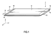
- FIG. 1 is a perspective view of a unit cell according to a first embodiment of the present invention.
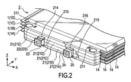
- FIG. 2 is a perspective view of a stacked battery according to the first embodiment of the present invention in which four unit cells are stacked.
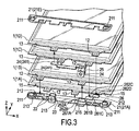
- FIG. 3 is an exploded perspective view of the stacked battery.
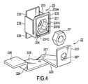
- FIG. 4 is an exploded perspective view of the positive electrode terminal and the positive electrode terminal support member.
- FIG. 5 is a perspective view of a positive electrode terminal to which a positive electrode terminal support member is attached.
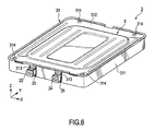
- FIG. FIG. 6 is a perspective view of the battery module according to the first embodiment of the present invention in which the stacked battery is accommodated in the battery case.
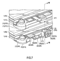
- FIG. 7 is an exploded perspective view in which a positive electrode terminal portion of the stacked battery is enlarged.
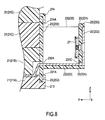
- FIG. 8 is shown in FIG.
- FIG. 7 is a sectional view taken along line VIII-VIII.
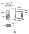
- FIG. 9 is a diagram for explaining a method of attaching the positive electrode terminal support member.
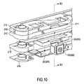
- FIG. 10 is an exploded perspective view in which the positive electrode terminal portion of the laminated battery according to the second embodiment of the present invention is enlarged.
- FIG. 11 is shown in FIG. It is XI-XI sectional drawing of 10.
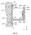
- FIG. 12 is a cross-sectional view showing a configuration for holding a positive electrode terminal support member according to a third embodiment of the present invention.
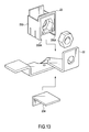
- FIG. 13 is a cross-sectional view showing the configuration of a positive electrode terminal support member according to a fourth embodiment of the present invention.
- FIG. 14 is a cross-sectional view of the main part of the stacked battery for explaining the state of stress concentration when the terminal is not fixedly supported by the terminal support member.
- FIG. 1 is a perspective view of a cell 1 according to a first embodiment of the present invention.
- the unit cell 1 includes a power generation element that can be charged / discharged, an exterior member 11 that houses the power generation element, and a plate-like positive electrode tab 12 and a negative electrode tab 13 for taking out the electric power of the power generation element to the outside. And it is a flat lithium ion secondary battery.
- the power generation element includes an electrode laminate in which positive plates and negative plates are alternately laminated via separators and an electrolyte. Since the structure and principle of the power generation element are well known, a detailed description thereof will be omitted.
- the exterior member 11 has a rectangular shape in plan view, and is configured by a laminate film in which a synthetic resin layer is laminated on both surfaces of a metal foil.
- the exterior member 11 accommodates the power generation element therein by forming the flange 14 by thermally welding the outer peripheral portions of the two laminate films in a state where the power generation element is accommodated.
- Two fixing holes 15 into which spacer fixing pins 212 (see FIG. 3) to be described later are inserted are formed in the flange 14 on the short side of the exterior member 11.
- the positive electrode tab 12 and the negative electrode tab 13 are respectively provided on one short side of the exterior member 11.
- FIG. 2 is a perspective view of a stacked battery 2 according to the first embodiment of the present invention in which four single cells 1 are stacked, and is a perspective view on the short side where a positive electrode tab 12 and a negative electrode tab 13 are provided.
- FIG. 3 is an exploded perspective view of the stacked battery 2.
- FIG. 2 and FIG. The stacked battery 2 will be described with reference to FIG. FIG.
- the stacked battery 2 includes four unit cells 1, five spacers 21, a positive terminal (bus bar) 22, a positive terminal support member 23, a negative terminal (bus bar) 24, Negative electrode terminal support member 25.
- the positive electrode terminal 22 and the negative electrode terminal 24 are terminals for power input / output, respectively.
- a unit cell 1A, a unit cell 1B, a unit cell 1C, and a unit cell 1D in order from the lower unit cell 1 in the figure.
- each of the five spacers 21 is a plate-like member made of a synthetic resin material having excellent electrical insulation.
- Bolt insertion holes 211 for inserting bolts for fixing the laminated battery 2 to a battery case 31 (see FIG. 6) to be described later are formed at both ends of the five spacers 21.
- the five spacers 21 are laminated so as to sandwich the flange 14 on the short side where the positive electrode tab 12 and the negative electrode tab 13 are provided. That is, the short side flange 14, the positive electrode tab 12, and the negative electrode tab 13 of the unit cell 1A are sandwiched between the spacer 21A and the spacer 21B.
- the flange 14, the positive electrode tab 12, and the negative electrode tab 13 on the short side of the unit cell 1B are sandwiched between the spacer 21B and the spacer 21C.
- the flange 14, the positive electrode tab 12, and the negative electrode tab 13 on the short side of the unit cell 1C are sandwiched between the spacer 21C and the spacer 21D.
- the flange 14, the positive electrode tab 12, and the negative electrode tab 13 on the short side of the unit cell 1D are sandwiched between the spacer 21D and the spacer 21E.
- the flange 14 on the short side where the positive electrode tab 12 and the negative electrode tab 13 are not provided is similarly sandwiched by another five spacers 21.
- FIG. As shown in FIG. 3, fixing pins 212 that protrude from the upper surface of the spacer 21A and are inserted into the fixing holes 15 formed in the flange 14 of the unit cell 1A are formed at both ends of the laminated surface of the spacer 21A.
- Fixing pins having the same function are also formed on the spacers 21B, 21C, and 21D.
- L-shaped engagement claws 213 projecting from the upper surface are formed at both ends of the laminated surface of the spacer 21A. This engagement claw 213 engages with an L-shaped engagement hole (not shown) formed on the lower surface of the spacer 21B.
- the engaging claw 213 of the spacer 21A engages with the engaging hole of the spacer 21B, whereby the spacer 21A and the spacer 21B are connected.
- Similar engagement claws are formed on the spacers 21B, 21C, and 21D, and similar engagement holes are formed on the spacers 21C, 21D, and 21E. Adjacent spacers 21 are connected to each other by engaging the holes.
- An intermediate terminal (bus bar) 26 is arranged on the right side of the laminated surface of the spacer 21A in the drawing, and a part of the positive electrode terminal 22 is arranged on the left side.
- the intermediate terminal 26 is formed by bending a strip-shaped conductor not provided with an insulating coating, and has a stepped shape having three bent portions 261A to 261C and four flat surfaces 262A to 262D. .
- the first flat surface 262A is sandwiched between the spacer 21A and the spacer 21B after the negative electrode tab 13 of the unit cell 1A is superimposed on the flat surface 262A and joined by ultrasonic welding or the like.
- the flat surface 262B of the second stage is sandwiched between the spacer 21B and the spacer 21C after the negative electrode tab 13 of the unit cell 1B is superimposed on the flat surface 262B and joined by ultrasonic welding or the like.
- the flat surface 262C of the third stage is sandwiched between the spacer 21C and the spacer 21D after the positive electrode tab 12 of the unit cell 1C is superimposed on the flat surface 262C and joined by ultrasonic welding or the like.
- the fourth flat surface 262D is sandwiched between the spacer 21D and the spacer 21E after the positive electrode tab 12 of the unit cell 1D is superimposed on the flat surface 262D and joined by ultrasonic welding or the like.
- the positive electrode terminal 22 is formed by bending a strip-shaped conductor not provided with an insulating coating.
- the positive terminal support member 23 is a synthetic resin box having insulating properties, and is attached to the positive terminal 22.
- FIG. 4 and FIG. 5 will be further described.
- FIG. 4 is an exploded perspective view of the positive electrode terminal 22 and the positive electrode terminal support member 23.
- FIG. FIG. 5 is a perspective view of a state in which the positive terminal support member 23 is attached to the positive terminal 22.
- the positive terminal 22 and the positive terminal support member 23 are integrated by, for example, insert molding.
- the positive electrode terminal 22 includes a torsion part 221, a terminal part 222, a support member attachment part 223, a bent part 224, a first joint part 225, and a second joint part 226.
- the twisted portion 221 is formed in the vicinity of the center of the conductor by twisting one end side of the conductor and then tilting the one end side of the conductor in a right angle direction.
- the terminal portion 222 is formed by causing the end portion on one end side of the conductor tilted in the right-angle direction to be raised at a substantially right angle.
- the terminal portion 222 has a substantially square flat plate shape, and a bolt insertion hole 227 is formed at the center.
- the bolt insertion hole 227 fastens an appropriate connection member for electrically connecting the positive electrode terminal 22 and an input / output terminal of another stacked battery 2 or a terminal of an external device such as a motor with a bolt. It is provided for this purpose.
- the support member mounting portion 223 is a flat region formed between the twisted portion 221 and the terminal portion 222.
- the positive terminal support member 23 is attached to the support member attachment portion 223.
- the bent portion 224 is formed by bending the vicinity of the center between the twisted portion 221 and the other end of the conductor.
- the first joint portion 225 is a flat region from the twisted portion 221 to the bent portion 224.
- the first joint portion 225 is sandwiched between the spacer 21A and the spacer 21B after the positive electrode tab 12 of the unit cell 1A is overlapped and joined by ultrasonic welding or the like.
- the second joint portion 226 is a flat region from the bent portion 224 to the other end of the conductor.
- the second joint 226 is sandwiched between the spacer 21B and the spacer 21C after the positive electrode tab 12 of the unit cell 1B is overlapped and joined by ultrasonic welding or the like.
- the positive terminal support member 23 includes a front wall 231, a back wall 232, a side wall 233, and a bottom wall 234.
- a hexagonal recess 231A corresponding to the outer shape of the nut 27 incorporated in the positive terminal support member 23 is formed.
- the nut 27 is a member for screwing a bolt used when fastening the connection member to the terminal portion 222 of the positive electrode terminal 22, and is press-fitted and fixed to the concave portion 231 ⁇ / b> A and held by the front wall 231.
- a bolt insertion hole 231B is formed in the front wall 231 closer to the back wall 232 than the recess 231A, and the tip of the bolt screwed into the nut 27 is inserted through the bolt insertion hole 227 of the positive terminal 22.
- a rectangular insertion hole 231C for inserting the support member mounting portion 223 of the positive electrode terminal 22 is formed below the recess 231A.
- a rectangular insertion hole 232A (see FIG. 8) for inserting the support member attachment portion 223 is formed in the back wall 232, and the support member attachment portion 223 is inserted into each of the insertion holes 231C and 232A.
- An outer edge wall 235 extending toward the terminal portion 222 side of the positive electrode terminal 22 is formed on the outer edge of the front wall 231. The outer edge wall 235 is formed so as to cover the outer edge of the terminal portion 222 when the positive terminal support member 23 is attached to the positive terminal.
- the terminal portion 222 is held by the outer edge wall 235.
- the back wall 232 has a rectangular shape extending upward in the drawing from the upper end surface 235A of the outer edge wall 235 and extending downward in the drawing from the bottom wall 234.
- the lower end portion of the back wall 232 is fitted to a portion 213 partially protruding from the side surface of the spacer 21A toward the terminal portion 222 side of the positive electrode terminal 22, and the upper end portion of the back wall 232 is The spacer 21A is fitted into a portion 214 that partially protrudes from the side surface of the spacer 21A toward the terminal portion 222 side of the positive electrode terminal 22.
- the positive terminal support member 23 is held by the spacer 21 ⁇ / b> A and the spacer 21 ⁇ / b> D, and the positive terminal 22 is fixedly supported by the positive terminal support member 23.
- the bottom wall 234 is positioned below the support member mounting portion 223 of the positive electrode terminal 22 through which the insertion holes 231C and 232A of the front wall 231 and the back wall 232 are inserted, and supports the support member mounting portion 223.
- FIG. 2 and FIG. The negative electrode terminal 24 and the negative electrode terminal support member 25 will be described with reference to FIG.
- the negative electrode terminal 24 is formed by bending a strip-shaped conductor not provided with an insulating coating.
- the negative electrode terminal 24 has the same function as the positive electrode terminal 22, although the shape is different from the positive electrode terminal 22.
- the first joint portion 241 of the negative electrode terminal 24 is sandwiched between the spacer 21C and the spacer 21D after the negative electrode tab 13 of the unit cell 1C is overlapped and joined by ultrasonic welding or the like.
- the second joint portion 242 of the negative electrode terminal 24 is sandwiched between the spacer 21D and the spacer 21E after the negative electrode tab 13 of the unit cell 1D is superimposed and joined by ultrasonic welding or the like.
- the negative electrode terminal support member 25 is a synthetic resin box having insulating properties, and is attached to the negative electrode terminal 24.
- the negative electrode terminal support member 25 is different from the positive electrode terminal support member 23 in that a rectangular insertion hole formed in the front wall is located above the recess, but the other configuration and functions are the same. . And like the positive electrode terminal support member 23, it hold
- FIG. 6 is a perspective view of the battery module 3 according to the first embodiment of the present invention in which the stacked battery 2 is accommodated in the battery case 31.
- the battery case 31 includes a box-shaped lower case 311 having an upper opening, and an upper case 312 that closes the opening of the lower case 311.
- the lower case 311 and the upper case 312 are fixed by winding the respective outer edge portions together.
- the lower case 311 includes a notch 313 for causing the positive electrode terminal 22 and the negative electrode terminal 24 of the stacked battery 2 accommodated therein to protrude from the side surface of the lower case 311.
- Four insertion holes 314 are formed in the upper case 312 so as to correspond to the bolt insertion holes 211 formed in the spacer 21 of the stacked battery 2.
- the lower case 311 is also formed with four insertion holes (not shown) so as to correspond to the bolt insertion holes 211 formed in the spacer 21 of the stacked battery 2.
- the stacked battery 2 is fixed to the battery case 31 by inserting bolts into the insertion holes 314 of the upper case 312, the bolt insertion holes 211 of the stacked battery 2, and the insertion holes of the lower case 311.
- the battery module 3 formed in this way is mounted on an electric vehicle as an energy supply source, for example, and by connecting any number of battery modules 3 in series or in parallel via the positive terminal 22 and the negative terminal 24, An in-vehicle battery having a desired voltage and energy capacity is configured.
- the terminals 22 and 24 of one battery module 3 and the terminals 22 and 24 of the other battery module 3 are connected by an appropriate connecting member. To do.
- FIG. 14 is a cross-sectional view of the main part of the stacked battery for explaining the state of stress concentration when the terminal is not fixedly supported by the terminal support member, and is a diagram as a comparative example to which this embodiment is not applied.
- FIG. 14 As shown in FIG.
- FIG. 7 and FIG. 8 how the positive electrode terminal support member 23 is held by the spacer 21 and fixedly supports the positive electrode terminal 22 will be described.
- FIG. 7 is an exploded perspective view in which the vicinity of the positive electrode terminal support member 23 of the stacked battery 2 is enlarged.
- FIG. 8 is shown in FIG. FIG. 7 is a sectional view taken along line VIII-VIII.
- FIG. 7 the spacer 21 ⁇ / b> A is formed with a portion 213 that partially protrudes from the side surface of the spacer 21 ⁇ / b> A toward the terminal portion 222 side of the positive electrode terminal 22.
- FIG. 8 As shown in FIG. 8, a fitting groove 213 ⁇ / b> A in which the lower end portion of the back wall 232 of the positive electrode terminal support member 23 is fitted is formed in the protruding portion 213. Also, FIG.
- the spacer 21 ⁇ / b> D is formed with a portion 214 that partially protrudes from the side surface of the spacer 21 ⁇ / b> D toward the terminal portion 222 side of the positive electrode terminal 22.
- FIG. 8 a fitting groove 214 ⁇ / b> A into which the upper end portion of the back wall 232 of the positive electrode terminal support member 23 is fitted is formed in the protruding portion 214.
- the positive electrode terminal support member 23 attached to the positive electrode terminal 22 is held by the spacer 21 ⁇ / b> A and the spacer 21 ⁇ / b> D in this manner, so that the positive electrode terminal 22 is fixedly supported by the positive electrode terminal support member 23.
- the external force by the rotational torque and vibration at the time of screw fastening is added to the positive electrode terminal 22, it can suppress that stress concentrates on the 1st junction part 225 and the 2nd junction part 226. That is, the rotation of the positive terminal 22 when a bolt is fastened to the terminal portion 222 of the positive terminal 22 and the vibration of the positive terminal 22 during traveling can be suppressed.
- the outer periphery of the terminal portion 222 of the positive electrode terminal 22 is covered with an outer edge wall 235, and the terminal portion 222 of the positive electrode terminal 22 is held by the outer edge wall 235. Thereby, the rotation of the positive terminal 22 when a bolt is fastened to the terminal portion 222 of the positive terminal 22 and the vibration of the positive terminal 22 during traveling can be further suppressed.
- the negative electrode terminal 24 is also fixedly supported by the negative electrode terminal support member 25 in the same manner as the positive electrode terminal 22, it is possible to suppress poor bonding with the negative electrode tab 13 also in the negative electrode terminal 24.
- the positive electrode terminal support member 23 and the negative electrode terminal support member 25 are superior for the following reason. That is, the unit cell 1 constituted by a flexible laminate film or the like is likely to change in volume in the stacking direction due to charge and discharge. Therefore, for example, when the positive electrode terminal support member 23 is held by the battery case 31, the positive electrode terminal support member 23 and the respective joints that are bonded to the positive electrode tab 12 of the unit cell 1 due to the volume change of the unit cell 1. The position will change.
- FIG. 9 is a diagram illustrating a method for attaching the positive electrode terminal support member 23.
- the lower end portion of the back wall 232 of the positive electrode terminal support member 23 attached to the positive electrode terminal 22 is inserted into the fitting groove 213A formed in the portion 213 partially protruding from the spacer 21A. Fit.
- the spacer 21B is stacked on the spacer 21A
- the spacer 21C is stacked on the spacer 21B.
- the spacer 21D is stacked on the spacer 21C while fitting the upper end portion of the back wall 232 of the positive electrode terminal support member 23 into the fitting groove 214A formed in the portion 214 partially protruding from the spacer 21D.
- FIG. 10 and FIG. A second embodiment of the present invention will be described with reference to FIG. FIG.
- FIG. 10 is an enlarged perspective view of the positive electrode terminal 22 portion of the stacked battery 2 according to the second embodiment of the present invention.
- FIG. 11 is shown in FIG. It is XI-XI sectional drawing of 10.
- FIG. 10 and FIG. As shown in FIG. 11, in the second embodiment of the present invention, only the spacer 21 ⁇ / b> D is formed with a fitting groove 214 ⁇ / b> A that fits with the upper end portion of the back wall 232 of the positive terminal support member 23. Even in this case, since the first joint portion 225 of the positive terminal 22 is sandwiched between the spacer 21A and the spacer 21B, the positive terminal support member 23 is held by the spacer 21A, the spacer 21B, and the spacer 21D as a result. Will be.
- the positive electrode terminal 22 can be fixedly held, the same effect as in the first embodiment can be obtained.
- the present invention is not limited to the above-described embodiment, and it is obvious that various modifications can be made within the scope of the technical idea.
- the positive electrode terminal 22 and the negative electrode terminal 24 are illustrated and described as output terminals.
- the present invention is not limited to this, and may be a voltage detection terminal for measuring the voltage of the battery module 3. Good.
- the lower end part and upper end part of the back surface wall 232 of the positive electrode terminal support member 23 were fitted to the fitting groove provided in spacer 21A and spacer 21D, it is set as the structure opposite to this. Good.
- fitting grooves 232B and 232C are provided at the lower end and upper end of the back wall 232 of the positive electrode terminal support member 23, and the protrusions 213B and 214B formed on the spacer 21A and the spacer 21D are provided in the fitting grooves 232B and 232C. You may make it fit. Further, the structure in which the spacer 21 and the positive electrode terminal support member 23 are fitted is not limited to such a projection and groove. Moreover, in the said Example, although the positive electrode terminal 22 and the positive electrode terminal support member 23 were integrally molded, FIG. As shown in FIG. 13, the bottom wall 234 may be separated and attached later by a snap fit claw 233 ⁇ / b> A or the like provided at the lower end of the side wall 233. Regarding the above description, the contents of Japanese Patent Application No. 2009-118228 in Japan with an application date of May 15, 2009 and the contents of Japanese Patent Application No. 2010-111330 in Japan with an application date of May 13, 2010 Are incorporated herein by reference.
- the present invention brings about a particularly preferable effect in application to an in-vehicle battery in which a plurality of battery modules 3 are connected.
- Exclusive properties or features encompassed by embodiments of the invention are claimed as follows.
Landscapes
- Chemical & Material Sciences (AREA)
- Chemical Kinetics & Catalysis (AREA)
- Electrochemistry (AREA)
- General Chemical & Material Sciences (AREA)
- Engineering & Computer Science (AREA)
- Manufacturing & Machinery (AREA)
- Connection Of Batteries Or Terminals (AREA)
- Battery Mounting, Suspending (AREA)
Abstract
Description
本発明の目的は、したがって、電極タブと出力端子との接合部に応力が集中するのを抑制することである。
上記目的を達成するため、本発明では、電極タブを有する扁平型電池が複数積層されてなる積層型電池において、電極タブの短絡を防止するように配置された絶縁部材と、電極タブに接続された端子とを有し、端子の先端側を絶縁部材に設けた支持部材により支持する。
この発明の詳細並びに他の特徴や利点は、明細書の以降の記載の中で説明されるとともに、添付された図面に示される。
Fig.2は、単電池を4枚積層したこの発明の第1の実施例による積層型電池の斜視図である。
Fig.3は、積層型電池の分解斜視図である。
Fig.4は、正極端子と正極端子支持部材の分解斜視図である。
Fig.5は、正極端子支持部材を取り付けた正極端子の斜視図である。
Fig.6は、積層型電池を電池ケースの内部に収容したこの発明の第1の実施例による電池モジュールの斜視図である。
Fig.7は、積層型電池の正極端子部分を拡大した分解斜視図である。
Fig.8は、Fig.7のVIII−VIII断面図である。
Fig.9は、正極端子支持部材の取り付け方法を説明する図である。
Fig.10は、この発明の第2の実施例による積層型電池の正極端子部分を拡大した分解斜視図である。
Fig.11は、Fig.10のXI−XI断面図である。
Fig.12は、この発明の第3の実施例による正極端子支持部材を保持する構成を示した断面図である。
Fig.13は、この発明の第4の実施例による正極端子支持部材の構成を示した断面図である。
Fig.14は、端子支持部材によって端子を固定支持しなかった場合の応力集中の様子を説明する積層型電池要部の横断面図である。
単電池1は、充放電可能な発電要素と、発電要素を内部に収容する外装部材11と、発電要素の電力を外部に取り出すための板状の正極タブ12及び負極タブ13と、を備える薄型かつ扁平なリチウムイオン二次電池である。
発電要素は、セパレータを介して正極板と負極板とを交互に積層させた電極積層体と電解質とから構成される。発電要素の構造及び原理については周知であるため、その詳細な説明については省略する。
外装部材11は、平面視において長方形状をしており、金属箔の両面に合成樹脂層を積層したラミネートフィルムで構成される。外装部材11は、発電要素を収容した状態で2枚のラミネートフィルムの外周部を熱溶着してフランジ14を形成することで、発電要素を内部に収容する。外装部材11の短辺側のフランジ14には、後述するスペーサの固定ピン212(Fig.3参照)が挿入される固定孔15がそれぞれ2つずつ形成される。
正極タブ12及び負極タブ13は、外装部材11の一方の短辺側にそれぞれ設けられる。正極タブ12の一端は外装部材11の外部にあり、正極タブ12の他端は外装部材11の内部で発電要素を構成する正極板に接続される。負極タブ13の一端は外装部材11の外部にあり、負極タブ13の他端は外装部材11の内部で発電要素を構成する負極板に接続される。
Fig.2は、単電池1を4枚積層したこの発明の第1の実施例による積層型電池2の斜視図であり、正極タブ12及び負極タブ13が設けられている短辺側の斜視図である。Fig.3は、積層型電池2の分解斜視図である。
以下、Fig.2及びFig.3を参照して積層型電池2について説明する。
Fig.2に示すように、積層型電池2は、4枚の単電池1と、5枚のスペーサ21と、正極端子(バスバ)22と、正極端子支持部材23と、負極端子(バスバ)24と、負極端子支持部材25と、を備える。正極端子22及び負極端子24は、それぞれ電力入出力用の端子である。
以下の説明において、4枚の単電池1を特に区別する必要があるときは、図中下側の単電池1から順に単電池1A、単電池1B、単電池1C、単電池1Dという。同様に、5枚のスペーサ21を特に区別する必要があるときは、図中下側のスペーサ21から順にスペーサ21A、スペーサ21B、スペーサ21C、スペーサ21D、スペーサ21Eという。Fig.3では、5枚のスペーサ21のうち最下段のスペーサ21Aと最上段のスペーサ21Eのみを記載してある。
Fig.2に示すように、4枚の単電池1は、相互に密着し、かつ、正極タブ12及び負極タブ13が同一方向に存在するように積層される。
5枚のスペーサ21は、それぞれ電気絶縁性に優れた合成樹脂材料等からなる板状の部材である。5枚のスペーサ21の両端には、後述する電池ケース31(Fig.6参照)に積層型電池2を固定するためのボルトを挿入するためのボルト挿入孔211が形成される。
また、5枚のスペーサ21は、正極タブ12及び負極タブ13が設けられた短辺側のフランジ14を挟むようにそれぞれ積層される。すなわち、単電池1Aの短辺側のフランジ14、正極タブ12、及び負極タブ13は、スペーサ21Aとスペーサ21Bによって挟まれる。単電池1Bの短辺側のフランジ14、正極タブ12、及び負極タブ13は、スペーサ21Bとスペーサ21Cによって挟まれる。単電池1Cの短辺側のフランジ14、正極タブ12、及び負極タブ13は、スペーサ21Cとスペーサ21Dによって挟まれる。単電池1Dの短辺側のフランジ14、正極タブ12、及び負極タブ13は、スペーサ21Dとスペーサ21Eによって挟まれる。なお、正極タブ12及び負極タブ13が設けられていない短辺側のフランジ14も同様に別の5枚のスペーサ21によって挟まれる。
Fig.3に示すように、スペーサ21Aの積層面の両端には、その上面から突出し、単電池1Aのフランジ14に形成された固定孔15に挿入される固定ピン212がそれぞれ形成される。スペーサ21B、スペーサ21C、及びスペーサ21Dにも同様の機能を有する固定ピンが形成される。
また、スペーサ21Aの積層面の両端にはさらに、その上面から突出するL字状の係合爪213がそれぞれ形成される。この係合爪213は、スペーサ21Bの下面に形成されるL字状の係合穴(図示せず)に係合する。スペーサ21Aの係合爪213がスペーサ21Bの係合穴に係合することで、スペーサ21Aとスペーサ21Bとが連結する。スペーサ21B、スペーサ21C、及びスペーサ21Dにも同様の係合爪が形成され、スペーサ21C、スペーサ21D、及びスペーサ21Eにも同様の係合穴が形成されており、それぞれの係合爪と係合穴とが係合することで隣接するスペーサ21同士が連結している。
そして、スペーサ21Aの積層面の図中右側に中間端子(バスバ)26が配置され、左側に正極端子22の一部が配置される。
中間端子26は、絶縁被膜を施していない帯状の導体を曲げ加工して形成したものであり、3つの屈曲部261A~261Cと4つの平坦面262A~262Dを持つ階段状の形をしている。1段目の平坦面262Aは、その平坦面262Aに単電池1Aの負極タブ13を重ね合わして超音波溶接等によって接合した上でスペーサ21Aとスペーサ21Bによって挟まれる。2段目の平坦面262Bは、その平坦面262Bに単電池1Bの負極タブ13を重ね合わして超音波溶接等によって接合した上でスペーサ21Bとスペーサ21Cによって挟まれる。3段目の平坦面262Cは、その平坦面262Cに単電池1Cの正極タブ12を重ね合わして超音波溶接等によって接合した上でスペーサ21Cとスペーサ21Dによって挟まれる。4段目の平坦面262Dは、その平坦面262Dに単電池1Dの正極タブ12を重ね合わして超音波溶接等によって接合した上でスペーサ21Dとスペーサ21Eによって挟まれる。
正極端子22は、絶縁被膜を施していない帯状の導体を曲げ加工して形成したものである。正極端子支持部材23は、絶縁性を有する合成樹脂性の箱体であり、正極端子22に取り付けられている。正極端子22及び正極端子支持部材23については、Fig.4及びFig.5をさらに参照して説明する。
Fig.4は、正極端子22と正極端子支持部材23の分解斜視図である。Fig.5は、正極端子22に正極端子支持部材23を取り付けた状態の斜視図である。本実施例では、正極端子22と正極端子支持部材23とは、例えばインサート成形により一体化される。
正極端子22は、ねじり部221と、端子部222と、支持部材取付部223と、屈曲部224と、第1接合部225と、第2接合部226と、を備える。
ねじり部221は、導体の一端側をねじりながら引き起こした後、その導体の一端側を直角方向に倒すことで導体の中央近傍に形成される。
端子部222は、直角方向に倒した導体の一端側の端部をさらに略直角に引き起こすことで形成される。端子部222は、略正方形の平板状となっており、中央にボルト挿通孔227が形成される。ボルト挿通孔227は、この正極端子22と、例えば別の積層型電池2の入出力端子やモータなどの外部機器の端子と、を電気的に接続するための適当な接続部材をボルトによって締結するために設けられたものである。
支持部材取付部223は、ねじり部221と端子部222との間に形成される平坦な領域である。支持部材取付部223に正極端子支持部材23が取り付けられる。
屈曲部224は、ねじり部221から導体の他端までの間の中央付近を折り曲げることで形成される。
第1接合部225は、ねじり部221から屈曲部224までの平坦な領域である。第1接合部225は、そこに単電池1Aの正極タブ12を重ね合わして超音波溶接等によって接合した上でスペーサ21Aとスペーサ21Bによって挟まれる。
第2接合部226は、屈曲部224から導体の他端までの平坦な領域である。第2接合部226は、そこに単電池1Bの正極タブ12を重ね合わして超音波溶接等によって接合した上でスペーサ21Bとスペーサ21Cによって挟まれる。
正極端子支持部材23は、正面壁231と、背面壁232と、側面壁233と、底面壁234と、を備える。
正面壁231の中央には、正極端子支持部材23に組み込まれるナット27の外形に対応する六角形状をした凹部231Aが形成される。ナット27は、正極端子22の端子部222に接続部材を締結するときに用いられるボルトを螺合させるための部材であり、凹部231Aに圧入固定されて正面壁231によって保持される。
凹部231Aよりも背面壁232側の正面壁231にはボルト挿通孔231Bが形成されており、正極端子22のボルト挿通孔227を通してナット27に螺合させたボルトの先端部が挿通する。
凹部231Aの下方には正極端子22の支持部材取付部223を挿通するための矩形の挿通孔231Cが形成される。なお、背面壁232にも同様に支持部材取付部223を挿通するための矩形の挿通孔232A(Fig.8参照)が形成されており、各挿通孔231C,232Aに支持部材取付部223を挿通させることで、正極端子支持部材23が正極端子22に取り付けられる。
正面壁231の外縁には、正極端子22の端子部222側に向かって延出する外縁壁235が形成される。外縁壁235は、正極端子支持部材23を正極端子に取り付けたときに、端子部222の外縁を覆うように形成される。この外縁壁235によって、端子部222が保持される。
背面壁232は、外縁壁235の上端面235Aよりも図中上方に延び、かつ底面壁234よりも図中下方に延びた長方形状をしている。ここで、Fig.2に示すように、背面壁232の下端部は、スペーサ21Aの側面から正極端子22の端子部222側に部分的に突出した部位213に嵌合しており、背面壁232の上端部は、スペーサ21Aの側面から正極端子22の端子部222側に部分的に突出した部位214に嵌合している。これにより、正極端子支持部材23がスペーサ21Aとスペーサ21Dによって保持されて、正極端子支持部材23によって正極端子22が固定支持される。なお、正極端子指示部材23が具体的にどのようにスペーサ21Aとスペーサ21Dによって保持されているかは、Fig.7及びFig.8を参照して後述する。
底面壁234は、正面壁231及び背面壁232の各挿通孔231C,232Aを挿通させた正極端子22の支持部材取付部223の下方に位置し、その支持部材取付部223を支持する。
再び、Fig.2及びFig.3を参照して負極端子24及び負極端子支持部材25について説明する。
負極端子24は、絶縁被膜を施していない帯状の導体を曲げ加工して形成したものである。負極端子24は、正極端子22と形状こそ相違するものの、正極端子22と同様の機能を有する。
負極端子24の第1接合部241は、そこに単電池1Cの負極タブ13を重ね合わして超音波溶接等によって接合した上でスペーサ21Cとスペーサ21Dによって挟まれる。負極端子24の第2接合部242は、そこに単電池1Dの負極タブ13を重ね合わして超音波溶接等によって接合した上でスペーサ21Dとスペーサ21Eによって挟まれる。
負極端子支持部材25は、絶縁性を有する合成樹脂性の箱体であり、負極端子24に取り付けられている。負極端子支持部材25は、正面壁に形成される矩形の挿通孔が凹部の上方に位置する点が正極端子支持部材23と相違しているが、その他は同様の構成及び機能を有している。そして、正極端子支持部材23と同様に、スペーサ21Aの側面から部分的に突出した部位215と、スペーサ21Dの側面から部分的に突出した部位216と、によって保持される。
Fig.6は、積層型電池2を電池ケース31の内部に収容したこの発明の第1の実施例による電池モジュール3の斜視図である。
電池ケース31は、上部が開口している箱状のロアケース311と、ロアケース311の開口を閉じるアッパケース312と、を備える。ロアケース311とアッパケース312とは、それぞれの外縁部を互いに巻き締めることで固定される。
ロアケース311は、内部に収容された積層型電池2の正極端子22及び負極端子24をロアケース311の側面から突出させるための切欠313を備える。
アッパケース312には、積層型電池2のスペーサ21に形成されたボルト挿入孔211に対応するように、4つの挿入孔314が形成される。また、ロアケース311にも積層型電池2のスペーサ21に形成されたボルト挿入孔211に対応するように、4つの挿入孔(図示せず)が形成されている。積層型電池2は、アッパケース312の挿入孔314、積層型電池2のボルト挿入孔211及びロアケース311の挿入孔にボルトを挿入することによって、電池ケース31に固定される。
このようにして形成される電池モジュール3は、例えばエネルギ供給源として電気自動車に搭載され、任意の数の電池モジュール3を正極端子22及び負極端子24を介して直列又は並列に接続することで、所望の電圧及びエネルギ容量の車載電池が構成される。
ここで、車載電池として電池モジュール3同士を電気的に接続するときは、一方の電池モジュール3の各端子22,24と他方の電池モジュール3の各端子22,24とを適当な接続部材によって接続する。このとき、接続部材は各端子22,24にねじ締め等によって締結される。そのため、各端子22,24にはねじ締め時の回転トルクが外力として加わるとともに、車両走行時には振動による外力も加わることになる。
そうすると、本実施例のように正極端子支持部材23や負極端子支持部材25によって正極端子22や負極端子24を固定支持しない場合には、以下のような問題点が生じる。
Fig.14は、端子支持部材によって端子を固定支持しなかった場合の応力集中の様子を説明する積層型電池要部の横断面図であり、本実施例を適用しない比較例としての図である。
Fig.14に示すように、端子支持部材によって端子401を固定支持しない状態で、スペーサ402から突出している端子401の一端側にねじ締め時の回転トルクや振動による外力が加わると、単電池403の電極タブ404と重なり合うようにスペーサ402によって挟まれている端子401の接合部に応力が集中してしまう。その結果、電極タブ404と端子401との物理的な接触が不十分となって、電池モジュールの出力が低下してしまう。
そこで本実施例では、端子支持部材によって端子を固定支持し、電極タブと端子との接続部に応力が集中するのを抑制したのである。
以下、Fig.7及びFig.8を参照して正極端子支持部材23がどのようにスペーサ21によって保持されて正極端子22を固定支持しているのかを説明する。
Fig.7は、積層型電池2の正極端子支持部材23の近傍を拡大した分解斜視図である。Fig.8は、Fig.7のVIII−VIII断面図である。
Fig.7に示すように、スペーサ21Aには、スペーサ21Aの側面から正極端子22の端子部222側に部分的に突出した部位213が形成される。そして、Fig.8に示すように、その突出した部位213に正極端子支持部材23の背面壁232の下端部が嵌合する嵌合溝213Aが形成される。
また、Fig.7に示すように、スペーサ21Dには、スペーサ21Dの側面から正極端子22の端子部222側に部分的に突出した部位214が形成される。そして、Fig.8に示すようにその突出した部位214に、正極端子支持部材23の背面壁232の上端部が嵌合する嵌合溝214Aが形成される。
正極端子支持部材23の背面壁232の下端部をスペーサ21Aに形成された嵌合溝213Aに、上端部をスペーサ21Dに形成された嵌合溝214Aに嵌合させることで、正極端子支持部材23は、スペーサ21A及びスペーサ21Dによって保持される。そして、正極端子22に取り付けられた正極端子支持部材23をこのようにスペーサ21A及びスペーサ21Dによって保持することで、正極端子22が正極端子支持部材23によって固定支持される。
これにより、正極端子22にねじ締め時の回転トルクや振動による外力が加わったときに、第1接合部225及び第2接合部226に応力が集中するのを抑制できる。すなわち、正極端子22の端子部222にボルトを締結したときの正極端子22の回転や、走行時における正極端子22の振動を抑制することができる。したがって、正極端子22の第1接合部225及び第2接合部226と単電池1A及び単電池1Bの正極タブ12との接合不良を抑制できる。
また、正極端子22の端子部222の外周は外縁壁235によって覆われており、この外縁壁235によって正極端子22の端子部222が保持されている。これにより、正極端子22の端子部222にボルトを締結したときの正極端子22の回転や、走行時における正極端子22の振動をさらに抑制することができる。
なお、負極端子24も正極端子22と同様に負極端子支持部材25によって固定支持されているので、負極端子24においても負極タブ13との接合不良を抑制できる。
ここで、正極端子支持部材23及び負極端子支持部材25を電池ケース31によって保持することも考えられるが、以下の理由により本実施例のほうが優れている。
すなわち、柔軟性を有するラミネートフィルム等によって構成された単電池1は、充放電により積層方向に体積変化が生じやすい。そのため、例えば正極端子支持部材23を電池ケース31によって保持すると、単電池1の体積変化によって、正極端子支持部材23と、単電池1の正極タブ12と接合している各接合部と、の相対位置が変化してしまう。その結果、正極タブ12と各接合部の間で接触不良が生じやすくなってしまう。
これに対し、本実施例では、正極端子支持部材23及び負極端子支持部材25をスペーサ21によって保持しているので、単電池1に体積変化が生じても、正極端子支持部材23と各接合部との相対位置の変化が極めて少ない。そのため、正極タブ12と各接合部との間で接触不良が生じにくい。
Fig.9は、正極端子支持部材23の取り付け方法を説明する図である。
正極端子支持部材23を取り付けるときには、まず正極端子22に取り付けられた正極端子支持部材23の背面壁232の下端部を、スペーサ21Aから部分的に突出した部位213に形成された嵌合溝213Aに嵌合させる。
次に、スペーサ21Aにスペーサ21Bを、スペーサ21Bにスペーサ21Cを積層する。
その後、スペーサ21Dから部分的に突出した部位214に形成された嵌合溝214Aに正極端子支持部材23の背面壁232の上端部を嵌合させつつ、スペーサ21Cにスペーサ21Dを積層する。
このように、本実施例ではスペーサ21A及びスペーサ21Dから部分的に突出した部位213,214に嵌合溝213A,214Aを形成したので、スペーサ21を積層していく一連の作業工程の中で簡易に正極端子支持部材23を取り付けることができる。
そのため、積層方向以外の方向に部品を取り付けるといった複雑な工程を伴うことがないので、製造工程の自動化が容易であるとともに、従来のスペーサ積層作業と実質的に同一の作業で正極端子支持部材23を取り付けることができる。したがって、製造工数の増加を抑制することができる。
次に、Fig.10及びFig.11を参照して、この発明の第2の実施例を説明する。
Fig.10は、この発明の第2の実施例による積層型電池2の正極端子22部分を拡大した斜視図である。Fig.11は、Fig.10のXI−XI断面図である。
Fig.10及びFig.11に示すように、この発明の第2の実施例では、スペーサ21Dにのみ、正極端子支持部材23の背面壁232の上端部と嵌合する嵌合溝214Aを形成している。この場合であっても、正極端子22の第1接合部225が、スペーサ21Aとスペーサ21Bとによって挟まれているため、結果としてスペーサ21A、スペーサ21B、及びスペーサ21Dによって正極端子支持部材23が保持されることになる。よって、正極端子22を固定保持できるので、第1の実施例と同様の効果を得ることができる。
なお、本発明は上記の実施形態に限定されずに、その技術的な思想の範囲内において種々の変更がなしうることは明白である。
例えば、上記実施例では出力端子として正極端子22及び負極端子24を例示して説明したが、これに限られるものではなく、電池モジュール3の電圧を測定するための電圧検出用端子であってもよい。
また、上記実施例ではスペーサ21A及びスペーサ21Dに設けた嵌合溝に正極端子支持部材23の背面壁232の下端部及び上端部を嵌合させていたが、これとは逆の構造にしてもよい。例えばFig.12に示すように、正極端子支持部材23の背面壁232の下端及び上端に嵌合溝232B,232Cを設け、この嵌合溝232B,232Cにスペーサ21A及びスペーサ21Dに形成した突起213B,214Bを嵌合させてもよい。また、スペーサ21と正極端子支持部材23とが嵌合する構造もこのような突起と溝によるものに限られるものではない。
また、上記実施例では正極端子22と正極端子支持部材23とを一体成形していたが、例えばFig.13に示すように、底面壁234を別体として、両側面壁233の下端に設けたスナップフィット爪233A等によって後から取り付けるようにしてもよい。
以上の説明に関して2009年5月15日を出願日とする日本国における特願2009−118228号の内容と、2010年5月13日を出願日とする日本国における特願2010−111330号の内容と、をここに引用により組み込む。
この発明の実施例が包含する排他的性質あるいは特徴は以下のようにクレームされる。
Claims (18)
- 電極タブを有する扁平型電池が複数積層されてなる積層型電池であって、
前記電極タブの短絡を防止するように配置された絶縁部材と、
前記電極タブと接続された端子と、を有し、
前記端子の先端側が、前記絶縁部材に設けた支持部材により支持されている、
ことを特徴とする積層型電池。 - 請求項1に記載の積層型電池において、
前記支持部材は、前記絶縁部材に保持されている、
ことを特徴とする。 - 請求項1に記載の積層型電池において、
前記絶縁部材は、当該絶縁部材から外側へ突出する保持部を有し、
前記保持部は、前記扁平型電池の積層方向に前記支持部材を保持する、
ことを特徴とする。 - 請求項3に記載の積層型電池において、
前記保持部は、一の絶縁部材から外側へ突出する第1保持部と、前記一の絶縁部材とは異なる他の絶縁部材から外側へ突出する第2保持部とを含み、
前記第1保持部及び前記第2保持部は、前記扁平型電池の積層方向の両側から前記支持部材を保持する、
ことを特徴とする。 - 請求項1に記載の積層型電池において、
前記端子の基端側は、複数の前記絶縁部材により保持されている、
ことを特徴とする。 - 請求項1に記載の積層型電池において、
前記絶縁部材は、当該絶縁部材から外側へ突出する保持部を有し、
前記支持部材は、前記端子の一端側を支持する壁面と、前記保持部に保持される被保持部とを含む、
ことを特徴とする。 - 請求項6に記載の積層型電池において、
前記保持部は、一の絶縁部材から外側へ突出する第1保持部と、前記一の絶縁部材とは異なる他の絶縁部材から外側へ突出する第2保持部とを含み、
前記被保持部は、前記第1保持部及び前記第2保持部によって保持される被保持部を含む、
ことを特徴とする。 - 請求項6に記載の積層型電池において、
前記端子は、基端側に前記電極タブが接合される接合部を備え、
前記接合部は、複数の前記絶縁部材により保持されている、
ことを特徴とする。 - 請求項6に記載の積層型電池において、
前記壁面に、前記端子と外部機器の端子とを固定する固定部を有する積層型電池。 - 請求項1に記載の積層型電池において、
前記積層型電池を電池ケースに収納する、
ことを特徴とする。 - 請求項10に記載の積層型電池において、
前記電池ケースは、前記端子を当該電池ケースの外部に導出させる孔部を備える、
ことを特徴とする。 - 請求項1に記載の積層型電池において、
前記端子は、前記支持部材が取り付けられる支持部材取付部を先端側に備え、
前記支持部材は、前記支持部材取付部に取り付けられたときに、前記扁平型電池の積層方向に延びる壁部を備え、
前記絶縁部材は、前記扁平型電池の積層方向と直行する方向に突出して前記壁部を保持する保持部を備える、
ことを特徴とする。 - 請求項12に記載の積層型電池において、
前記保持部は、前記壁部が嵌合する開口部を備える、
ことを特徴とする。 - 請求項12に記載の積層型電池において、
前記保持部は、前記扁平型電池の積層方向と平行な方向に突出する突出部をさらに備え、
前記壁部は、前記突出部が嵌合する開口部を備える、
ことを特徴とする。 - 請求項12に記載の積層型電池において、
前記壁部は、前記扁平型電池の積層方向上方に延びる、
ことを特徴とする。 - 請求項12に記載の積層型電池において、
前記壁部は、前記扁平型電池の積層方向上方及び下方に延びる、
ことを特徴とする。 - 請求項12に記載の積層型電池において、
前記端子は、基端側が複数の前記絶縁部材によって挟持され、先端側がその絶縁部材から突出している、
ことを特徴とする。 - 電極タブを有する扁平型電池と、前記電極タブの短絡を防止する絶縁部材と、を交互に積層して構成する積層型電池の製造方法であって、
電力入出力用の端子の基端側に形成される接合部に前記電極タブを接合し、
前記端子の先端側が前記絶縁部材の側面から突出するように前記端子の接合部を前記絶縁部材によって挟むと同時に、前記端子の先端側に取り付けられた支持部材を前記絶縁部材によって保持する、
ことを特徴とする積層型電池の製造方法。
Priority Applications (7)
| Application Number | Priority Date | Filing Date | Title |
|---|---|---|---|
| US13/266,226 US9153807B2 (en) | 2009-05-15 | 2010-05-14 | Laminated battery and manufacturing method thereof |
| EP10775030.9A EP2432048B1 (en) | 2009-05-15 | 2010-05-14 | Stacked cell and method for manufacturing same |
| BRPI1010544-1A BRPI1010544B1 (pt) | 2009-05-15 | 2010-05-14 | Bateria laminada e método de fabricação da mesma |
| CN201080020332.6A CN102422464B (zh) | 2009-05-15 | 2010-05-14 | 层叠型电池及其制造方法 |
| RU2011151071/07A RU2483395C1 (ru) | 2009-05-15 | 2010-05-14 | Многослойная аккумуляторная батарея и способ ее изготовления |
| KR1020117026674A KR101320283B1 (ko) | 2009-05-15 | 2010-05-14 | 적층형 전지 및 그의 제조 방법 |
| MX2011011956A MX2011011956A (es) | 2009-05-15 | 2010-05-14 | Celda apilada y metodo para fabricar la misma. |
Applications Claiming Priority (4)
| Application Number | Priority Date | Filing Date | Title |
|---|---|---|---|
| JP2009118228 | 2009-05-15 | ||
| JP2009-118228 | 2009-05-15 | ||
| JP2010-111330 | 2010-05-13 | ||
| JP2010111330A JP5657273B2 (ja) | 2009-05-15 | 2010-05-13 | 積層型電池、電池モジュール及び積層型電池の製造方法 |
Publications (1)
| Publication Number | Publication Date |
|---|---|
| WO2010131780A1 true WO2010131780A1 (ja) | 2010-11-18 |
Family
ID=43085145
Family Applications (1)
| Application Number | Title | Priority Date | Filing Date |
|---|---|---|---|
| PCT/JP2010/058575 Ceased WO2010131780A1 (ja) | 2009-05-15 | 2010-05-14 | 積層型電池及びその製造方法 |
Country Status (9)
| Country | Link |
|---|---|
| US (1) | US9153807B2 (ja) |
| EP (1) | EP2432048B1 (ja) |
| JP (1) | JP5657273B2 (ja) |
| KR (1) | KR101320283B1 (ja) |
| CN (1) | CN102422464B (ja) |
| BR (1) | BRPI1010544B1 (ja) |
| MX (1) | MX2011011956A (ja) |
| RU (1) | RU2483395C1 (ja) |
| WO (1) | WO2010131780A1 (ja) |
Cited By (10)
| Publication number | Priority date | Publication date | Assignee | Title |
|---|---|---|---|---|
| JP2012123980A (ja) * | 2010-12-07 | 2012-06-28 | Auto Network Gijutsu Kenkyusho:Kk | 電池モジュール及びプレート組立体 |
| CN102738432A (zh) * | 2011-03-31 | 2012-10-17 | Nec能源元器件株式会社 | 电池组 |
| WO2014103709A1 (ja) * | 2012-12-27 | 2014-07-03 | 日産自動車株式会社 | 電池モジュールおよび組電池 |
| WO2015079496A1 (ja) * | 2013-11-26 | 2015-06-04 | 日産自動車株式会社 | 組電池 |
| US9142840B2 (en) | 2011-10-21 | 2015-09-22 | Blackberry Limited | Method of reducing tabbing volume required for external connections |
| WO2016021288A1 (ja) * | 2014-08-08 | 2016-02-11 | 日産自動車株式会社 | 電池モジュールの製造装置 |
| JP2017147048A (ja) * | 2016-02-15 | 2017-08-24 | Fdk株式会社 | 蓄電モジュール |
| WO2018055676A1 (ja) * | 2016-09-20 | 2018-03-29 | 株式会社東芝 | 組電池および導電部材 |
| WO2018055677A1 (ja) * | 2016-09-20 | 2018-03-29 | 株式会社東芝 | 組電池および導電部材 |
| US10446828B2 (en) | 2011-10-21 | 2019-10-15 | Blackberry Limited | Recessed tab for higher energy density and thinner batteries |
Families Citing this family (16)
| Publication number | Priority date | Publication date | Assignee | Title |
|---|---|---|---|---|
| JP2012089323A (ja) * | 2010-10-19 | 2012-05-10 | Nifco Inc | 電池モジュール用電極構成体 |
| JP2013016381A (ja) * | 2011-07-05 | 2013-01-24 | Auto Network Gijutsu Kenkyusho:Kk | 電池配線モジュール |
| JP6051753B2 (ja) | 2012-10-10 | 2016-12-27 | 株式会社オートネットワーク技術研究所 | 蓄電モジュール |
| US9553289B2 (en) * | 2013-07-26 | 2017-01-24 | Samsung Sdi Co., Ltd. | Battery module |
| JP2015167102A (ja) * | 2014-03-04 | 2015-09-24 | 株式会社オートネットワーク技術研究所 | 蓄電モジュール |
| JP2015167103A (ja) * | 2014-03-04 | 2015-09-24 | 株式会社オートネットワーク技術研究所 | 蓄電モジュール |
| WO2016052934A1 (ko) * | 2014-09-29 | 2016-04-07 | 주식회사 엘지화학 | 애노드, 이를 포함하는 리튬 이차 전지, 상기 리튬 이차 전지를 포함하는 전지 모듈 및 애노드의 제조방법 |
| US10396405B2 (en) * | 2014-11-10 | 2019-08-27 | Te Connectivity Corporation | Bus bar for a battery connector system |
| KR101941415B1 (ko) * | 2015-10-22 | 2019-01-22 | 닛산 지도우샤 가부시키가이샤 | 조전지 |
| US11251484B2 (en) | 2016-09-26 | 2022-02-15 | Envision Aesc Japan Ltd. | Assembly including unit cell and spacer |
| JP6812453B2 (ja) * | 2016-11-07 | 2021-01-13 | 株式会社エンビジョンAescジャパン | スペーサ、組電池、および組電池の製造方法 |
| WO2018110231A1 (ja) * | 2016-12-16 | 2018-06-21 | 三洋電機株式会社 | 防水構造のバッテリシステム |
| JP7325014B2 (ja) * | 2018-03-27 | 2023-08-14 | パナソニックIpマネジメント株式会社 | 蓄電モジュール |
| CN110767865B (zh) * | 2018-07-26 | 2020-11-20 | 宁德时代新能源科技股份有限公司 | 隔离板组件及电池模组 |
| KR102367381B1 (ko) * | 2018-12-26 | 2022-02-23 | 주식회사 엘지에너지솔루션 | 이물질 유입 방지 구조를 갖는 배터리 모듈, 이를 포함하는 배터리 팩 및 자동차 |
| KR102901201B1 (ko) | 2020-02-13 | 2025-12-17 | 주식회사 엘지에너지솔루션 | 고정력이 향상된 hv 터미널 너트 및 분리 커버를 포함하는 배터리 모듈 및 이를 포함하는 배터리 팩 |
Citations (5)
| Publication number | Priority date | Publication date | Assignee | Title |
|---|---|---|---|---|
| JP2003288883A (ja) * | 2001-09-04 | 2003-10-10 | Nec Corp | 単電池及び組電池 |
| JP2005222703A (ja) * | 2004-02-03 | 2005-08-18 | Shin Kobe Electric Mach Co Ltd | 組電池間の接続構造及び組電池 |
| WO2006073071A1 (ja) * | 2005-01-04 | 2006-07-13 | Nec Corporation | フィルム外装電気デバイス用ケースおよびフィルム外装電気デバイス集合体 |
| JP2006210312A (ja) | 2004-10-26 | 2006-08-10 | Nissan Motor Co Ltd | 組電池 |
| JP2009037785A (ja) * | 2007-07-31 | 2009-02-19 | Calsonic Kansei Corp | バッテリの電池モジュール構造における接続端子の溶接方法 |
Family Cites Families (15)
| Publication number | Priority date | Publication date | Assignee | Title |
|---|---|---|---|---|
| US5867363A (en) | 1992-09-18 | 1999-02-02 | Pinnacle Research Institute, Inc. | Energy storage device |
| US5821033A (en) | 1992-09-18 | 1998-10-13 | Pinnacle Research Institute, Inc. | Photolithographic production of microprotrusions for use as a space separator in an electrical storage device |
| US5800857A (en) | 1992-09-18 | 1998-09-01 | Pinnacle Research Institute, Inc. | Energy storage device and methods of manufacture |
| US5384685A (en) | 1992-09-18 | 1995-01-24 | Pinnacle Research Institute, Inc. | Screen printing of microprotrusions for use as a space separator in an electrical storage device |
| US5464453A (en) | 1992-09-18 | 1995-11-07 | Pinnacle Research Institute, Inc. | Method to fabricate a reliable electrical storage device and the device thereof |
| US5711988A (en) * | 1992-09-18 | 1998-01-27 | Pinnacle Research Institute, Inc. | Energy storage device and its methods of manufacture |
| DE4240337C2 (de) * | 1992-12-01 | 1997-06-19 | Deutsche Automobilgesellsch | Elektrochemischer Speicher und Verfahren zu dessen Herstellung |
| DE69805683T2 (de) * | 1997-02-18 | 2003-02-06 | Koninklijke Philips Electronics N.V., Eindhoven | Dünnschichtakkumulatorvorrichtung bestehend aus elektrochemischer Zelle und elektrischen Kontaktmitteln |
| JP2001357835A (ja) * | 2000-06-14 | 2001-12-26 | Yazaki Corp | バッテリ用ターミナルの接続構造 |
| TWI221345B (en) * | 2001-03-30 | 2004-09-21 | Sanyo Gs Soft Energy Co Ltd | Battery pack |
| KR100556101B1 (ko) | 2003-12-16 | 2006-03-03 | 주식회사 엘지화학 | 이차전지 모듈 |
| JP4990757B2 (ja) | 2004-05-19 | 2012-08-01 | エルジー・ケム・リミテッド | 安全素子を備えた電池 |
| PL2590242T3 (pl) * | 2004-12-24 | 2020-01-31 | Lg Chem, Ltd. | Sposób i urządzenie do polepszania działania modułu akumulatorowego przez wyrównywanie napięcia |
| KR100891079B1 (ko) | 2005-02-07 | 2009-03-30 | 주식회사 엘지화학 | 전지 모듈용 전지 카트리지 연결 시스템 |
| JP5070697B2 (ja) | 2005-12-19 | 2012-11-14 | 日産自動車株式会社 | 電池モジュール |
-
2010
- 2010-05-13 JP JP2010111330A patent/JP5657273B2/ja active Active
- 2010-05-14 WO PCT/JP2010/058575 patent/WO2010131780A1/ja not_active Ceased
- 2010-05-14 KR KR1020117026674A patent/KR101320283B1/ko active Active
- 2010-05-14 CN CN201080020332.6A patent/CN102422464B/zh active Active
- 2010-05-14 US US13/266,226 patent/US9153807B2/en active Active
- 2010-05-14 RU RU2011151071/07A patent/RU2483395C1/ru active
- 2010-05-14 EP EP10775030.9A patent/EP2432048B1/en active Active
- 2010-05-14 BR BRPI1010544-1A patent/BRPI1010544B1/pt not_active IP Right Cessation
- 2010-05-14 MX MX2011011956A patent/MX2011011956A/es active IP Right Grant
Patent Citations (5)
| Publication number | Priority date | Publication date | Assignee | Title |
|---|---|---|---|---|
| JP2003288883A (ja) * | 2001-09-04 | 2003-10-10 | Nec Corp | 単電池及び組電池 |
| JP2005222703A (ja) * | 2004-02-03 | 2005-08-18 | Shin Kobe Electric Mach Co Ltd | 組電池間の接続構造及び組電池 |
| JP2006210312A (ja) | 2004-10-26 | 2006-08-10 | Nissan Motor Co Ltd | 組電池 |
| WO2006073071A1 (ja) * | 2005-01-04 | 2006-07-13 | Nec Corporation | フィルム外装電気デバイス用ケースおよびフィルム外装電気デバイス集合体 |
| JP2009037785A (ja) * | 2007-07-31 | 2009-02-19 | Calsonic Kansei Corp | バッテリの電池モジュール構造における接続端子の溶接方法 |
Non-Patent Citations (1)
| Title |
|---|
| See also references of EP2432048A4 |
Cited By (18)
| Publication number | Priority date | Publication date | Assignee | Title |
|---|---|---|---|---|
| JP2012123980A (ja) * | 2010-12-07 | 2012-06-28 | Auto Network Gijutsu Kenkyusho:Kk | 電池モジュール及びプレート組立体 |
| US9356278B2 (en) | 2011-03-31 | 2016-05-31 | Nec Energy Devices, Ltd. | Battery pack |
| CN102738432A (zh) * | 2011-03-31 | 2012-10-17 | Nec能源元器件株式会社 | 电池组 |
| CN104766936A (zh) * | 2011-03-31 | 2015-07-08 | Nec能源元器件株式会社 | 电池组 |
| US10446828B2 (en) | 2011-10-21 | 2019-10-15 | Blackberry Limited | Recessed tab for higher energy density and thinner batteries |
| US9142840B2 (en) | 2011-10-21 | 2015-09-22 | Blackberry Limited | Method of reducing tabbing volume required for external connections |
| US9437845B2 (en) | 2012-12-27 | 2016-09-06 | Nissan Motor Co., Ltd. | Battery module and battery pack |
| JP6036850B2 (ja) * | 2012-12-27 | 2016-12-07 | 日産自動車株式会社 | 電池モジュールおよび組電池 |
| WO2014103709A1 (ja) * | 2012-12-27 | 2014-07-03 | 日産自動車株式会社 | 電池モジュールおよび組電池 |
| WO2015079496A1 (ja) * | 2013-11-26 | 2015-06-04 | 日産自動車株式会社 | 組電池 |
| JPWO2015079496A1 (ja) * | 2013-11-26 | 2017-03-16 | 日産自動車株式会社 | 組電池 |
| US10468647B2 (en) | 2013-11-26 | 2019-11-05 | Envision Aesc Japan Ltd. | Battery pack |
| WO2016021288A1 (ja) * | 2014-08-08 | 2016-02-11 | 日産自動車株式会社 | 電池モジュールの製造装置 |
| JPWO2016021288A1 (ja) * | 2014-08-08 | 2017-04-27 | 日産自動車株式会社 | 電池モジュールの製造装置 |
| JP2017147048A (ja) * | 2016-02-15 | 2017-08-24 | Fdk株式会社 | 蓄電モジュール |
| WO2018055676A1 (ja) * | 2016-09-20 | 2018-03-29 | 株式会社東芝 | 組電池および導電部材 |
| WO2018055677A1 (ja) * | 2016-09-20 | 2018-03-29 | 株式会社東芝 | 組電池および導電部材 |
| JPWO2018055676A1 (ja) * | 2016-09-20 | 2019-06-24 | 株式会社東芝 | 組電池および導電部材 |
Also Published As
| Publication number | Publication date |
|---|---|
| CN102422464A (zh) | 2012-04-18 |
| JP5657273B2 (ja) | 2015-01-21 |
| EP2432048A1 (en) | 2012-03-21 |
| EP2432048B1 (en) | 2016-12-21 |
| EP2432048A4 (en) | 2014-01-22 |
| BRPI1010544B1 (pt) | 2020-05-12 |
| CN102422464B (zh) | 2015-01-14 |
| BRPI1010544A2 (pt) | 2016-03-15 |
| US9153807B2 (en) | 2015-10-06 |
| MX2011011956A (es) | 2011-12-08 |
| JP2010287568A (ja) | 2010-12-24 |
| KR101320283B1 (ko) | 2013-10-23 |
| US20120040234A1 (en) | 2012-02-16 |
| KR20120007530A (ko) | 2012-01-20 |
| RU2483395C1 (ru) | 2013-05-27 |
Similar Documents
| Publication | Publication Date | Title |
|---|---|---|
| WO2010131780A1 (ja) | 積層型電池及びその製造方法 | |
| KR101732285B1 (ko) | 조전지 및 조전지의 제조 방법 | |
| JP5058986B2 (ja) | 折り曲げ可能なバッテリーカートリッジ及び中または大型バッテリーモジュール | |
| EP3731302B1 (en) | Battery module, battery pack comprising same battery module, and vehicle comprising same battery pack | |
| WO2009107657A1 (ja) | 電池モジュールおよび電池モジュールの製造方法 | |
| CN101490871A (zh) | 中型或大型电池组模块 | |
| US20160164051A1 (en) | Secondary battery and battery pack including the same | |
| CN107925030A (zh) | 集成盒和包括该集成盒的电池组 | |
| JP2011198660A (ja) | 電池パック | |
| KR102210461B1 (ko) | 단위전지모듈과 이를 포함하는 전지모듈 및 전지모듈의 제조방법과 이를 포함하는 전지팩 | |
| JP6891597B2 (ja) | 蓄電装置 | |
| CN110620209A (zh) | 具有多个电极的电池及使用该电池的电池模块 | |
| JP7210519B2 (ja) | 電池セル及び電池モジュール | |
| KR20150070701A (ko) | 외부 입출력 단자를 형성하는 버스 바를 포함하는 전지모듈 | |
| JP2005166279A (ja) | 組電池 | |
| JP6973180B2 (ja) | 電池パック | |
| JP5514575B2 (ja) | モジュール用端子 | |
| JP2008147089A (ja) | 電池モジュールとその製造方法 | |
| JP2013114816A (ja) | 蓄電素子 | |
| JP2023012759A (ja) | 蓄電装置およびその車両搭載構造 | |
| JP7810823B2 (ja) | 組電池 | |
| JP2010211951A (ja) | 電池および電池の製造方法 | |
| JP2014032789A (ja) | 薄型電池 | |
| JP5114944B2 (ja) | 組電池 | |
| JP2026502117A (ja) | バッテリーモジュール |
Legal Events
| Date | Code | Title | Description |
|---|---|---|---|
| WWE | Wipo information: entry into national phase |
Ref document number: 201080020332.6 Country of ref document: CN |
|
| 121 | Ep: the epo has been informed by wipo that ep was designated in this application |
Ref document number: 10775030 Country of ref document: EP Kind code of ref document: A1 |
|
| WWE | Wipo information: entry into national phase |
Ref document number: 13266226 Country of ref document: US |
|
| ENP | Entry into the national phase |
Ref document number: 20117026674 Country of ref document: KR Kind code of ref document: A |
|
| WWE | Wipo information: entry into national phase |
Ref document number: MX/A/2011/011956 Country of ref document: MX |
|
| WWE | Wipo information: entry into national phase |
Ref document number: 4625/KOLNP/2011 Country of ref document: IN |
|
| NENP | Non-entry into the national phase |
Ref country code: DE |
|
| REEP | Request for entry into the european phase |
Ref document number: 2010775030 Country of ref document: EP |
|
| WWE | Wipo information: entry into national phase |
Ref document number: 2010775030 Country of ref document: EP |
|
| ENP | Entry into the national phase |
Ref document number: 2011151071 Country of ref document: RU Kind code of ref document: A |
|
| REG | Reference to national code |
Ref country code: BR Ref legal event code: B01A Ref document number: PI1010544 Country of ref document: BR |
|
| ENP | Entry into the national phase |
Ref document number: PI1010544 Country of ref document: BR Kind code of ref document: A2 Effective date: 20111111 |