WO2010134307A1 - マイクロ波加熱装置及びマイクロ波加熱方法 - Google Patents
マイクロ波加熱装置及びマイクロ波加熱方法 Download PDFInfo
- Publication number
- WO2010134307A1 WO2010134307A1 PCT/JP2010/003293 JP2010003293W WO2010134307A1 WO 2010134307 A1 WO2010134307 A1 WO 2010134307A1 JP 2010003293 W JP2010003293 W JP 2010003293W WO 2010134307 A1 WO2010134307 A1 WO 2010134307A1
- Authority
- WO
- WIPO (PCT)
- Prior art keywords
- power
- heating
- unit
- microwave
- frequency
- Prior art date
- Legal status (The legal status is an assumption and is not a legal conclusion. Google has not performed a legal analysis and makes no representation as to the accuracy of the status listed.)
- Ceased
Links
Images




Classifications
-
- H—ELECTRICITY
- H05—ELECTRIC TECHNIQUES NOT OTHERWISE PROVIDED FOR
- H05B—ELECTRIC HEATING; ELECTRIC LIGHT SOURCES NOT OTHERWISE PROVIDED FOR; CIRCUIT ARRANGEMENTS FOR ELECTRIC LIGHT SOURCES, IN GENERAL
- H05B6/00—Heating by electric, magnetic or electromagnetic fields
- H05B6/64—Heating using microwaves
- H05B6/70—Feed lines
- H05B6/705—Feed lines using microwave tuning
-
- H—ELECTRICITY
- H05—ELECTRIC TECHNIQUES NOT OTHERWISE PROVIDED FOR
- H05B—ELECTRIC HEATING; ELECTRIC LIGHT SOURCES NOT OTHERWISE PROVIDED FOR; CIRCUIT ARRANGEMENTS FOR ELECTRIC LIGHT SOURCES, IN GENERAL
- H05B6/00—Heating by electric, magnetic or electromagnetic fields
- H05B6/64—Heating using microwaves
- H05B6/66—Circuits
- H05B6/68—Circuits for monitoring or control
- H05B6/686—Circuits comprising a signal generator and power amplifier, e.g. using solid state oscillators
-
- H—ELECTRICITY
- H05—ELECTRIC TECHNIQUES NOT OTHERWISE PROVIDED FOR
- H05B—ELECTRIC HEATING; ELECTRIC LIGHT SOURCES NOT OTHERWISE PROVIDED FOR; CIRCUIT ARRANGEMENTS FOR ELECTRIC LIGHT SOURCES, IN GENERAL
- H05B6/00—Heating by electric, magnetic or electromagnetic fields
- H05B6/64—Heating using microwaves
- H05B6/66—Circuits
- H05B6/68—Circuits for monitoring or control
- H05B6/688—Circuits for monitoring or control for thawing
-
- Y—GENERAL TAGGING OF NEW TECHNOLOGICAL DEVELOPMENTS; GENERAL TAGGING OF CROSS-SECTIONAL TECHNOLOGIES SPANNING OVER SEVERAL SECTIONS OF THE IPC; TECHNICAL SUBJECTS COVERED BY FORMER USPC CROSS-REFERENCE ART COLLECTIONS [XRACs] AND DIGESTS
- Y02—TECHNOLOGIES OR APPLICATIONS FOR MITIGATION OR ADAPTATION AGAINST CLIMATE CHANGE
- Y02B—CLIMATE CHANGE MITIGATION TECHNOLOGIES RELATED TO BUILDINGS, e.g. HOUSING, HOUSE APPLIANCES OR RELATED END-USER APPLICATIONS
- Y02B40/00—Technologies aiming at improving the efficiency of home appliances, e.g. induction cooking or efficient technologies for refrigerators, freezers or dish washers
Definitions
- the present invention relates to a microwave heating apparatus and a microwave heating method provided with a microwave generation unit configured using a semiconductor element.
- microwave generators using semiconductor elements have been proposed in place of magnetrons commonly used as conventional microwave generators.
- a microwave generation unit using such a semiconductor element can be configured to be small and inexpensive, and has an advantage that the frequency of the generated microwave can be easily adjusted.
- the reflected power returning from the heating chamber side to the microwave generation unit side via the antenna becomes zero.
- the reflected power transmitted from the heating chamber side to the microwave generation unit side is generated based on the output impedance of the microwave generation unit and the impedance of the heating chamber.
- the electrical characteristics of the heating chamber containing the object to be heated vary depending on many conditions such as the type, shape, and amount of the object to be heated, and the position of the object to be heated, and the electrical characteristics of the heating chamber are always different. Yes. For this reason, not all microwave power is always absorbed in the object to be heated in the heating chamber, and reflected power is generated.
- a microwave heating apparatus it is common to use an isolator in order to eliminate the influence of reflected power.
- an isolator in order to eliminate the influence of reflected power.
- Japanese Unexamined Patent Publication No. 2006-128075 see Japanese Unexamined Patent Publication No. 2006-128075.
- the microwave heating device using the isolator can reliably eliminate the influence of the reflected power, and the semiconductor element of the microwave generation unit is not destroyed by the reflected power.
- Japanese Patent Laid-Open No. 56-96486 before an actual heating operation is performed, a microwave frequency is swept between predetermined frequency bands, and an oscillation frequency at which reflected power is minimized between the frequency bands is stored.
- a microwave heating apparatus having a configuration is disclosed. In the actual heating operation, this microwave heating apparatus radiates a microwave having an oscillation frequency stored in advance from an antenna in the heating chamber to heat an object to be heated in the heating chamber. By configuring in this way, this conventional high-frequency heating device aims to improve the power conversion efficiency.
- a microwave heating apparatus using a semiconductor element as a microwave generation unit in the case of a configuration that prevents the destruction of the semiconductor element due to reflected power using an isolator, the isolator is very expensive and is a bulky part. It was not preferable from the viewpoint of the increase in the size of the apparatus and the economical efficiency. Therefore, a conventional microwave heating apparatus using a magnetron as a microwave generation unit is robust against reflected power and is inexpensive, so that it is easy for a user to purchase and highly convenient.
- a microwave heating apparatus using a semiconductor element as a microwave generator, in a stage before performing an actual heating operation, the frequency at which the reflected power is minimized between predetermined frequency bands is searched and stored, There are some which perform a heating operation at a stored frequency.
- the heating operation is performed with the frequency stored in advance, so that the reflected power is a semiconductor element. It is a structure which cannot respond to the change of the reflected electric power during the heating operation, or a value that may cause damage.
- An object of the present invention is to provide a microwave heating apparatus and a microwave heating method capable of reliably preventing damage to a microwave generation part due to reflected power and heating a heated part in a heating chamber with high efficiency. .
- a microwave heating apparatus includes a heating chamber that accommodates an object to be heated, An oscillator that outputs a signal having an oscillation frequency within a predetermined frequency band; A power amplifying unit for amplifying the output of the oscillating unit; A power feeding unit that supplies the output of the power amplification unit to the heating chamber; A power detection unit that detects reflected power reflected from the heating chamber through the power feeding unit to the power amplification unit and power supplied from the power amplification unit to the power feeding unit; and reflection from the power detection unit A control unit that receives a power signal and a supply power signal and controls an oscillation frequency of the oscillation unit and an output of the power amplification unit; The control unit executes a frequency sweep operation in a predetermined frequency band with a frequency sweep power lower than a rated supply power supplied to the power supply unit during the heating operation before starting a heating operation on the object to be heated in the heating chamber.
- the microwave heating device can reliably prevent the microwave generating portion from being damaged by the reflected energy of the reflected power, and can heat the heated portion with high heating efficiency.
- the control unit performs a predetermined frequency sweep power before starting the heating operation for the object to be heated in the heating chamber.
- a frequency sweep operation in a frequency band is performed to determine an oscillation frequency at which the reflection ratio of the reflected power to the supplied power is a minimum value, and power is supplied to the power supply unit according to the minimum reflected power at the determined oscillation frequency It is configured to regulate power.
- the microwave heating device configured as described above can reduce the heating output when the reflected power is large, and conversely increase the heating output when the reflected power is small, and can be heated by the rated output. Become. For this reason, the microwave heating apparatus of the present invention prevents the semiconductor element used in the power amplification unit, which is a power unit, from being destroyed by the reflected energy of the reflected power during the heating operation without using an isolator.
- the control unit interrupts the heating operation for a predetermined time after starting the heating operation for the object to be heated in the heating chamber.
- Execute the frequency sweep operation in the predetermined frequency band with the frequency sweep power re-determine the oscillation frequency at which the reflection ratio of the reflected power to the supplied power is the minimum value, and according to the minimum reflected power at the re-determined oscillation frequency It is comprised so that the electric power supplied to the said electric power feeding part may be adjusted.
- the microwave heating apparatus increases the heating output when the reflection ratio is small and heats it at the rated output, and conversely reduces the heating output when the reflection ratio is large, Even if it is not used, it is possible to reliably prevent the semiconductor element of the power amplification unit, which is a power unit, from being destroyed by reflected energy during the heating operation.
- the control unit according to the first aspect is determined by performing a frequency sweep operation before starting the heating operation for the object to be heated in the heating chamber. After the heating operation with the generated oscillation frequency is started, the heating operation is interrupted and the frequency sweep operation is performed again to re-determine the oscillation frequency that is the minimum reflected power detected by the power detection unit, You may comprise so that it may transfer to heating operation with the determined oscillation frequency.
- the microwave heating apparatus according to the fourth aspect configured in this manner searches for an operating condition that minimizes reflected power by performing a frequency sweep operation before the heating operation, and performs the heating operation based on the search result.
- the optimum oscillation frequency is set again while the heating operation is stopped.
- a highly efficient heating operation can always be realized according to the state of the heated object.
- the control unit presets a heating operation and a heating operation stop in which the heating operation is interrupted and the frequency sweep operation is performed. You may comprise so that it may carry out repeatedly by the set time interval.
- the microwave heating apparatus according to the fifth aspect configured as described above is optimal every time a predetermined time elapses even when the impedance of the heating chamber varies greatly depending on the state of the object to be heated, for example, by thawing the object to be heated. Since the oscillation frequency is set appropriately, a highly efficient heating operation can be realized according to the state of the object to be heated.
- the control unit interrupts the heating operation and performs the frequency sweep operation. Further, it may be configured to perform the operation when the reflected power detected by the power detection unit becomes equal to or greater than a predetermined threshold value.
- the microwave heating device configured as described above is the optimum oscillation frequency again when the heating operation is stopped even when the impedance of the heating chamber differs greatly depending on the state of the object to be heated and the reflected power increases. Therefore, a highly efficient heating operation can be realized according to the state of the object to be heated.
- the reflected power detected by the power detection unit within the preset time is greater than or equal to a threshold value by the control unit according to the sixth aspect.
- the heating operation may be interrupted and the frequency sweep operation may be executed.
- the microwave heating apparatus according to the seventh aspect configured as described above stops the heating operation in consideration of a change in the impedance of the heating chamber even when the reflected power does not exceed the threshold during the heating operation. Therefore, the optimum oscillation frequency is set again, so that a highly efficient heating operation can be realized.
- the power distribution unit further distributes the output of the oscillation unit and supplies the output to the plurality of power amplification units.
- Provided, and outputs from the plurality of power amplifying units may be respectively supplied to the plurality of power feeding units to radiate microwaves to the heating chamber. Since the microwave heating device according to the eighth aspect configured as described above radiates microwaves from the plurality of power feeding units into the heating chamber, the microwaves are synthesized in the internal space of the heating chamber. As a result, the microwave heating apparatus of the eighth aspect can obtain high output by centrally feeding the heating chamber with the plurality of power feeding units, and can disperse the plurality of power feeding units in the heating chamber. Therefore, the space between the casing and the heating chamber constituting the external appearance can be effectively used, and the components can be efficiently arranged to reduce the size.
- a microwave heating apparatus according to a ninth aspect of the present invention, according to the first aspect to the seventh aspect, a power distribution unit that distributes an output of the oscillation unit and supplies the output to a plurality of power amplification units, A phase controller that varies the phase of the microwave power supplied to the plurality of power amplifiers; The output from the plurality of power amplification units may be supplied to the plurality of power feeding units, respectively, so as to radiate microwaves to the heating chamber.
- the microwave heating apparatus configured as described above is configured to radiate microwaves from a plurality of power feeding units into the heating chamber and to vary the phase difference between the power feeding units. By varying the phase difference in this way, it is possible to freely form an electromagnetic field distribution, and it is possible to selectively heat a specific part of the object to be heated.
- a microwave heating method includes a step of outputting a signal having an oscillation frequency within a predetermined frequency band by an oscillation unit, Amplifying the output of the oscillation unit by the power amplification unit; Supplying the output of the power amplification unit to the heating chamber by a power feeding unit; A step of detecting reflected power reflected from the heating chamber side to the power amplification unit by the power detection unit through the power supply unit and power supplied to the power supply unit from the power amplification unit; and A step of receiving a reflected power signal and a supply power signal from a power detection unit and controlling an oscillation frequency of the oscillation unit and an output of the power amplification unit; Before starting the heating operation for the object to be heated in the heating chamber, perform a frequency sweep operation in a predetermined frequency band with a frequency sweep power lower than the rated supply power that is microwave output to the object to be heated in the heating chamber during the heating operation.
- the microwave heating method of the 10th viewpoint comprised in this way can prevent the damage of the microwave generation part by reflected power reliably, and can heat the to-be-heated part in a heating chamber with high heating efficiency.
- a frequency sweep in a predetermined frequency band with a frequency sweep power is started before the heating operation for the object to be heated in the heating chamber is started.
- the microwave heating method according to the eleventh aspect configured as described above is such that when the reflected power is large, the heating output is decreased, and conversely, when the reflected power is small, the heating output is increased and heating can be performed with the rated output. Become. For this reason, the microwave heating method according to the eleventh aspect prevents the semiconductor element used in the power amplifying unit that is a power unit from being destroyed by the reflected energy of the reflected power during the heating operation without using an isolator. Yes.
- the frequency sweep of a predetermined frequency band with a frequency sweep power is started before the heating operation for the object to be heated in the heating chamber is started. Performing an operation to determine an oscillation frequency at which the reflected power detected by the power detector is minimized; After starting the heating operation with the determined oscillation frequency, performing the frequency sweep operation by interrupting the heating operation, and re-determining the oscillation frequency to be the minimum reflected power detected by the power detection unit; Transitioning to a heating operation at the re-determined oscillation frequency.
- the microwave heating method increases the heating output when the reflection ratio is small and heats it at the rated output, and conversely reduces the heating output when the reflection ratio is large, Even if it does not use, it can prevent that the semiconductor element of the power amplification part which is a power unit is destroyed by reflected energy during heating operation.
- the heating operation and the heating operation stop in which the heating operation is interrupted and the frequency sweep operation is performed are set at predetermined time intervals. You may repeat.
- the microwave heating method according to the thirteenth aspect configured as described above is optimal every time a predetermined time elapses even when the impedance of the heating chamber varies greatly depending on the state of the object to be heated, for example, by thawing the object to be heated. Since the oscillation frequency is set appropriately, a highly efficient heating operation can be realized according to the state of the object to be heated.
- the microwave heating method according to a fourteenth aspect of the present invention is the power detection unit according to the twelfth aspect, wherein after the heating operation is started, the heating operation is stopped by interrupting the heating operation and executing the frequency sweep operation. This may be performed when the reflected power detected by the above becomes equal to or greater than a predetermined threshold.
- the microwave heating method according to the fourteenth aspect configured as described above is the optimum oscillation frequency again when the heating operation is stopped even when the impedance of the heating chamber differs greatly depending on the state of the object to be heated and the reflected power increases. Therefore, a highly efficient heating operation can be realized according to the state of the object to be heated.
- the microwave heating method according to a fifteenth aspect of the present invention is the heating operation according to the twelfth aspect, when the reflected power detected by the power detection unit does not exceed a threshold value within a preset time. May be interrupted to execute the frequency sweep operation.
- the microwave heating method according to the fifteenth aspect configured as described above is to stop the heating operation and set the optimum oscillation frequency again even when the reflected power does not exceed the threshold value during the heating operation.
- a highly efficient heating operation can be realized according to the state of the object to be heated.
- the present invention it is possible to search for an operating condition in which the reflected power is minimized by the frequency sweep operation, and to reliably prevent the microwave generation unit from being damaged by the reflected energy of excessive reflected power during the heating operation.
- a microwave heating apparatus and a microwave heating method that can realize high heating efficiency can be provided.
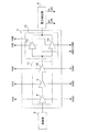
- the block diagram which shows the main structures of the electric power feeding path in the microwave heating device of Embodiment 1 which concerns on this invention The block diagram which shows the structure of the power amplification part in the microwave heating apparatus of Embodiment 1 which concerns on this invention.
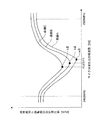
- the graph which shows the change of the reflective ratio of the reflected voltage (reflected wave) with respect to the supply voltage (transmitted wave) in the allowable frequency band of a microwave heating device Explanatory drawing which shows the process of the heating operation in the microwave heating apparatus of Embodiment 1 which concerns on this invention
- the block diagram which shows the main structures of the electric power feeding path in the microwave heating device of Embodiment 2 which concerns on this invention The block diagram which shows the main structures of the electric power feeding path in the microwave heating device of Embodiment 3 which concerns on this invention
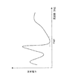
- the block diagram which shows the main structures of the electric power feeding path in the microwave heating apparatus of Embodiment 4 which concerns on this invention The graph which showed an example of the frequency characteristic curve of the reflected power detected in the electric power detection part in the microwave heating device of Embodiment 4 which concerns on this invention
- microwave heating apparatus of the present invention is not limited to the configuration of the microwave oven described in the following embodiment, but is equivalent to the technical idea described in the following embodiment and the present invention. It includes a microwave heating device configured based on common technical knowledge in the technical field.
- FIG. 1 is a block diagram showing a main configuration of a power feeding path in a microwave oven as the microwave heating apparatus according to the first embodiment of the present invention.
- an oscillation unit 2 configured using a semiconductor element outputs a signal having an oscillation frequency within a predetermined frequency band (for example, 2400 MHz to 2500 MHz).
- the power amplifying unit 3 that is a power unit is configured using a plurality of semiconductor elements having a function of amplifying the microwave power from the oscillating unit 2.
- the oscillation unit 2 and the power amplification unit 3 have a power flow in the microwave frequency band, but the power output from the oscillation unit 2 is relatively small.
- the power input from the oscillating unit 2 to the power amplifying unit 3 is a small power of several mW or less, is amplified by the power amplifying unit 3, and is supplied to the power feeding unit 5, which is an antenna, via the power detecting unit 4. Electric power can be supplied.
- the power detection unit 4 transmits the microwave output from the power amplification unit 3 and supplies the microwave output to the power supply unit 5, and detects the transmitted power transmitted through the power detection unit 4.
- This transmitted power is the supply power of the incident wave radiated from the power supply unit 5 into the heating chamber 7.
- the power detection unit 4 detects the reflected power of the reflected wave that returns from the heating chamber side to the power amplification unit 3 via the power feeding unit 5.
- the power detection unit 4 detects the supply power signal Pf supplied to the power supply unit 5 and the reflected power signal Pr received by the power supply unit 5 from the heating chamber side.
- the power supply unit 6 is constituted by a so-called insulation type AC-DC converter, and forms a power supply voltage Vdd supplied to the power amplification unit 3 and a ground line GND.
- the control unit 1 receives the supply power signal Pf and the reflected power signal Pr from the power detection unit 4, and calculates the reflection ratio (Pr / Pf) of the reflected power signal Pr with respect to the supply power signal Pf. Further, the control unit 1 outputs a frequency control signal Cf for changing the frequency of the oscillation unit 2 to the oscillation unit 2 based on the calculation result of the reflection ratio (Pr / Pf), and a power control signal Cp for changing the output power. Is output to the power amplifier 3.
- the supply voltage Vf in the supply power signal Pf and the reflection voltage in the reflection power signal Pr are used as the reflection ratio (Pr / Pf) between the supply power signal Pf and the reflected power signal Pr.
- the power feeding unit 5 is an antenna for radiating microwaves, and supplies the microwave power amplified by the power amplification unit 3 into the heating chamber 7.
- the microwave amplified in the power amplification unit 3 is propagated through the power detection unit 4 and radiated from the power supply unit 5 into the heating chamber 7.
- the power feeding unit 5 that is an antenna is disposed on the bottom surface of the heating chamber 7, and the power detection unit 4 is disposed on the bottom surface side outside the heating chamber 7.
- the power detection unit 4 and the power supply unit 5 are connected via a small-diameter opening formed in the bottom surface of the heating chamber 7.
- the microwave generation unit 20 in the microwave heating apparatus of the first embodiment includes a control unit 1, an oscillation unit 2, a power amplification unit 3, a power detection unit 4, and a power feeding unit 5.
- the microwave amplified in the power amplification unit 3 is supplied to the power supply unit 5 that is an antenna via the power detection unit 4, and is radiated from the power supply unit 5 to the heating chamber 7.
- the radiated microwave is absorbed by the heated object 15 placed on the mounting table 16 fixed inside the heating chamber 7, and is applied to the heated object 15 under the heating conditions set by the user. Perform dielectric heating.
- FIG. 2 is a block diagram showing the configuration of the power amplifying unit 3 in the microwave heating apparatus of the first embodiment.
- the power amplifier 3 is configured by providing a plurality of semiconductor elements in a circuit using a conductor pattern formed on one surface of a dielectric substrate made of a low dielectric loss material.
- the weak microwave output from the oscillation unit 2 is amplified by about 10 dB in each of the front-stage preamplifier 8, the middle-stage preamplifier 9, and the rear-stage preamplifier 10, and is amplified to a large power of about 10W.
- the amplification part composed of the pre-stage preamplifier 8, the middle stage preamplifier 9, and the rear stage preamplifier 10 is referred to as a driver unit 11.
- the output unit 12 at the rear stage of the driver unit 11 is configured by a parallel connection of a first final amplifier 13 and a second final amplifier 14 in order to amplify the power when large power (about 10 W) is input. Yes. Since the output unit 12 requires a gain of about 20 dB, the function is achieved by the parallel connection of the first final amplifier 13 and the second final amplifier 14.
- the power amplifying unit 3 configured as described above matching circuits are provided on the input side and the output side of each semiconductor element so that the semiconductor element, which is an amplifying element for amplifying microwaves, operates satisfactorily. .
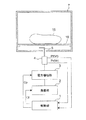
- FIG. 3 is a diagram illustrating a schematic configuration of the microwave heating apparatus according to the first embodiment.
- the power supply unit 6 shown in FIG. 1 is omitted.
- the microwave heating apparatus according to the first embodiment includes a heating chamber 7 having a substantially rectangular parallelepiped structure for housing an object to be heated 15.
- the heating chamber 7 includes a wall plate that forms a ceiling surface, a bottom surface, a left side surface, a right side surface, and a back surface with a metal material, an open / close door (not shown) that opens and closes in order to put in and out the heated object 15, and the heated object 15 It is comprised with the mounting base 16 for mounting.
- the heating chamber 7 configured as described above is configured such that the microwave supplied into the heating chamber is confined in the heating chamber by closing the open / close door.
- the rated high frequency output is in the range of about 700 W to 1000 W.
- the microwave heating apparatus according to the first embodiment has a configuration in which a high frequency output can be varied within a range of 700 W to 1000 W as a rated high frequency output.
- the heated object 15 to be heated by the microwave in the heating chamber 7 from a light load with extremely low water content such as popcorn, a medium load of stewed dishes using casserole, and a large load such as a large turkey, There are many different things. Furthermore, it may be used in an unloaded state where there is no object to be heated in the heating chamber 7 due to an erroneous operation by the user. Thus, the impedance in the heating chamber 7 as viewed from the power feeding unit 5 varies with a large width depending on the use situation. In addition, when thawing frozen food, the impedance may be close to an empty state due to the low dielectric constant of ice.
- the reflection ratio (Vr / Vf) of the reflection voltage Vr to the supply voltage Vf in the allowable frequency band (for example, 2400 MHz to 2500 MHz) of the microwave oven varies greatly depending on the type of load.
- FIG. 4 shows changes in the reflection ratio (Vr / Vf) of the reflected voltage Vr with respect to the supply voltage Vf in the allowable frequency band (2400 MHz to 2500 MHz) of the microwave oven for various loads.
- Vr / Vf the reflection ratio of the reflected voltage Vr with respect to the supply voltage Vf in the allowable frequency band (2400 MHz to 2500 MHz) of the microwave oven for various loads.
- curve A the case of a heated object corresponding to a load of 500 cc of water as a large load
- the case of a heated object corresponding to a load of 285 cc of water as a medium load and as a small load.
- the case of a heated object corresponding to a load of 90 cc of water is shown by curve C.
- the supply power of the microwave transmitted through the power detection unit 4 and supplied to the power supply unit 5 is substantially constant at a low power of 10 W, and a frequency sweep operation is performed within an allowable frequency band to obtain a predetermined value.
- the reflected power at the frequency at that time was measured every time.
- the frequency output from the oscillating unit 2 is selected as “F1”
- microwave energy can be efficiently absorbed by the heated object.
- the absorption of the microwave energy into the food which is the object to be heated is in the maximum state.
- the reflection ratio (Vr / Vf) being minimum is considered to be that the reflection power with respect to the microwave output at this time is also minimum.
- the supply power (Pf) to the power feeding unit is increased, the reflection power is reflected by this reflection ratio. (Pr) is generated. Therefore, even if the heating operation is performed at the rated output at the frequency F1, the semiconductor element of the power amplifying unit 3 is not excessively stressed by the reflected power, and the semiconductor element is not destroyed.
- the point c is the point with the smallest reflection ratio (Vr / Vf), and the frequency of the microwave at this point c is “F3”. Therefore, when the object to be heated corresponding to a load of 90 cc of water is heated, if the frequency output from the oscillation unit 2 is selected as “F3”, the microwave energy is efficiently absorbed by the object to be heated, The absorption of microwave energy into the food to be heated is at its maximum. Further, the fact that the reflection ratio (Vr / Vf) is the minimum is considered to be the minimum reflected power for the microwave output at this time.
- the frequency with the smallest reflection ratio (Vr / Vf) is selected. Even so, the reflected energy at the point b of the curve B and the point c of the curve C is larger than the reflected energy at the point a of the curve A. For this reason, when a rated high frequency output (for example, 700 W to 1000 W) is applied to the object to be heated at the selected frequency (F2 or F3), the semiconductor element of the power amplifying unit 3 is damaged by the reflected energy of the reflected power. There is a possibility of being destroyed.
- a rated high frequency output for example, 700 W to 1000 W
- the object to be heated is heated with an appropriate high-frequency output according to the reflection ratio at the selected oscillation frequency, and the power amplification unit 3 is supplied to the semiconductor element. It is configured to reduce the influence of the reflected power.
- the microwave heating apparatus according to the first embodiment means for heating with an appropriate high-frequency output according to the selected oscillation frequency will be described with reference to FIG.
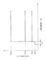
- FIG. 5 is an explanatory diagram showing a heating operation process in the microwave heating apparatus of the first embodiment.
- the vertical axis represents the microwave output [W]
- the horizontal axis represents the heat treatment time [second] of the microwave heating apparatus.
- the microwave heating apparatus of the first embodiment when the start key of the heating operation is pressed by the user, the heating operation is started.
- the microwave output is set to a minute output (frequency sweep power, for example, 10 W) as the first output “Ppre”.
- This first output “Ppre” is small power that does not destroy the semiconductor element of the power amplifying unit 3 due to the reflected energy even if 100% of the supplied power (Pf) returns as the reflected power (Pr). Has been selected.
- a frequency sweep operation for detecting a value at which the reflection ratio of the reflection voltage (Vr) to the supply voltage (Vf) is minimum is referred to as a minimum ratio search operation.
- the microwave heating apparatus according to the first embodiment will be described with reference to an example of performing a minimum ratio search operation for detecting a value at which the reflection ratio of the reflection voltage (Vr) to the supply voltage (Vf) is minimum. Includes a configuration for performing a minimum ratio search operation for detecting a value at which the reflection ratio of the reflected power (Pr) to the supplied power (Pf) is minimum, and can be realized by a similar configuration.
- the minimum ratio search operation starts when the user presses the start key of the heating operation and ends within the search period tp.
- the frequency of the microwave is performed every fixed frequency from the lowest frequency (for example, 2400 MHz) to the highest frequency (for example, 2500 MHz) in the detection target frequency band.
- the supply voltage (Vf) supplied from the power detection unit 4 to the power supply unit 5 and the reflected voltage (Vr) input to the power detection unit 4 from the heating chamber via the power supply unit 5 are sequentially detected.
- the oscillation frequency indicating the minimum reflection ratio value is detected.
- the search operation may be performed by a reciprocating operation.
- the control unit 1 compares the minimum reflection ratio (Vr / Vf) detected in the minimum ratio search operation with the first threshold value (T1) and the second threshold value (T2) set in advance.
- the first threshold value (T1) is set to a value smaller than the second threshold value (T2) (T1 ⁇ T2). If the minimum reflection ratio detected in the minimum ratio search operation is a value smaller than the first threshold value (T1), even if the actual heating operation is performed at the rated high frequency output with the oscillation frequency that is the minimum reflection ratio, it occurs at that time.
- the semiconductor device of the power amplifying unit 3 is not broken by the reflected energy of the reflected power. For this reason, in the microwave heating apparatus, the control unit 1 transmits and controls the power control signal Cp so that the power amplification unit 3 outputs the first rated high-frequency output (Pmax).
- the control unit 1 Control is performed so that the amplification unit 3 outputs a second rated high-frequency output (Pmid, for example, 850 W) lower than the first rated high-frequency output (Pmax, for example, 1000 W).
- the second rated high-frequency output (Pmid) in which the output of the power amplifier 3 is controlled is less than the breakdown limit so that the reflected energy generated at that time does not destroy the semiconductor element of the power amplifier 4 in consideration of the reflection ratio at that time. Is set to a small value. Therefore, even if the object to be heated is heated at the second rated high frequency output (Pmid), the semiconductor element of the power amplifying unit 3 is not destroyed by the reflected energy generated at that time.
- the control unit 1 indicates that the power amplification unit 3 has the second rated high frequency.
- Control is performed to output a third rated high-frequency output (Pmin, for example, 700 W) that is lower than the output (Pmid).
- the third rated high-frequency output (Pmin) in which the output of the power amplifying unit 3 is controlled is less than the destruction limit so that the reflected energy generated at that time does not destroy the semiconductor element of the power amplifying unit 3 in consideration of the reflection ratio at that time. Is set to a small value. Therefore, even if the object to be heated is heated at the third rated high frequency output (Pmin), the semiconductor element of the power amplifying unit 3 is not destroyed by the reflected energy generated at that time.
- a desired rated high-frequency output is selected from three rated high-frequency outputs (Pmax, Pmid, Pmin) using two threshold values (T1, T2).
- T1, T2 two threshold values
- the present invention is not limited to this example. In this invention, it can comprise so that it may select from several rated high frequency output using several threshold value.
- the microwave heating apparatus of the first embodiment even when a high frequency output is set under the heating conditions set by the user, the power amplification unit 3 is reflected by reflected energy in consideration of the safety of the apparatus.
- the semiconductor element is set so as not to be destroyed. That is, even when the user sets a high-frequency output, if the reflection ratio to the object to be heated at that time is poor, the maximum high-frequency output is set within a range in which the semiconductor element is not adversely affected by the reflected energy.
- the minimum ratio exploration operation here is called pre-search, and in the allowable frequency band (2400 to 2500 MHz), the supply power Pf (supply voltage Vf) and the reflected power Pr (reflection voltage Vr) are swept and measured at a certain frequency. Then, the reflection ratio Pr / Pf (Vr / Vf) is calculated. Based on the calculation result, the minimum reflection ratio is obtained, and the oscillation frequency at that time is set.
- a table indicating the relationship between the value of the minimum reflection ratio Pr / Pf (Vr / Vf) and the high-frequency output is set in advance.
- An appropriate high frequency output corresponding to the detected minimum reflection ratio Pr / Pf (Vr / Vf) value is calculated from the table, and the object to be heated is heated by the calculated high frequency output for optimization.
- a function of the heating output with a factor of the value of the minimum reflection ratio Pr / Pf (Vr / Vf) is set in advance, and the detected minimum reflection ratio Pr / Pf
- a method may be used in which the value of (Vr / Vf) is substituted into the function to calculate the high frequency output, and the object to be heated is optimized by the calculated high frequency output. This optimization method is carried out in the control unit 1, but it is desirable to use a microcomputer in order to use many operations.
- FIG. 6 is a graph showing a frequency characteristic curve related to the reflection ratio detected in the minimum ratio search operation in the microwave heating apparatus of the first embodiment.
- the frequency sweep operation (sweep operation) is automatically performed with the minimum frequency 2400 MHz of the allowable frequency band (2400 to 2500 MHz) as the starting point and the maximum frequency 2500 MHz as the final point.
- the supplied power (supply voltage) and the reflected power (reflected voltage) are measured at predetermined constant increment times (t1, t2,..., Tx,..., Tn), and the reflection ratio Pr /
- the value of Pf (Vr / Vf) is calculated sequentially.
- the value of the reflection ratio Pr / Pf (Vr / Vf) for each constant frequency from the minimum frequency of 2400 MHz. Is calculated.
- the value of the reflection ratio Pr / Pf (Vr / Vf) is sequentially calculated at every constant increase time (t1, t2,..., Tx,..., Tn ⁇ 1, tn).
- the minimum ratio search operation ends.
- the increase time ( ⁇ t), which is the measurement interval, is constant, and the minimum ratio search operation is executed n times during the search period tp, so one measurement time is tp / n.
- the frequency and the value of the reflection ratio Pr / Pf (Vr / Vf) are stored in the storage means provided in the control unit 1.
- the frequency Fmin at which the reflection ratio (Vr / Vf) is minimum at the time point tx is detected, and the value R1 of the reflection ratio (Vr / Vf) is obtained.
- the microwave output for heating is determined as described above.
- FIG. 7 is a block diagram showing a main configuration of a power feeding path in the microwave heating apparatus according to the second embodiment of the present invention.
- the microwave heating apparatus of the second embodiment includes a power distribution unit 17 at the subsequent stage of the oscillation unit 2.
- the power distribution unit 17 distributes the signal in the band of 2400 MHz to 2500 MHz from the oscillation unit 2 to the power amplification units 3a and 3b that are a plurality of power units.
- the microwaves amplified in each of the power amplification units 3a and 3b are configured such that the microwaves are radiated from the plurality of power supply units 5a and 5b through the respective power detection units 4a and 4b.
- the microwave heating apparatus since there is a limit to the power that can be amplified by the power amplifying unit that is one power unit, the power is amplified to a desired power using a plurality of power amplifying units. It is configured to supply. Therefore, in the microwave heating apparatus according to the second embodiment, the power handled in the power amplifying unit, which is one power unit, is reduced, and the microwaves amplified in the plurality of power amplifying units are spatially synthesized in the heating chamber and desired. The microwave output is to be obtained.
- the power distribution unit 17 used in the microwave heating apparatus according to the second embodiment is disposed after the oscillation unit of the small power system.
- the power distribution unit 17 may be an in-phase distributor that does not generate a phase difference between outputs, such as a Wilkinson distributor, or a phase difference between outputs such as a branch line type and a rat race type.
- the resulting distributor may be.
- the power distribution unit 17 propagates approximately half of the microwave high-frequency power input from the oscillation unit 2 to each of the power amplification units 3a and 3b.
- the microwave power amplified in each power amplifier 3a, 3b is transmitted to each power feeder 5a, 5b through each power detector 4a, 4b.
- the microwave power is transmitted in two lines after the power distribution unit 17.
- the microwave heating apparatus according to the second embodiment is compact in appearance and can be configured to have a large heating chamber. Therefore, a microwave heating apparatus having a small large-capacity heating chamber, for example, a microwave oven is provided. be able to.
- the present invention is not limited to this example, and a power distribution unit is further provided in the subsequent stage of the power distribution unit 17.
- a configuration in which four power supply units and eight power supply units are provided by using the multistage configuration provided or by configuring the power distribution unit 17 with a multi-branch distribution circuit that distributes power to three or more systems. Is possible.
- the power handled in the power amplification unit which is a power unit is further reduced, and the power handled in the output unit of the power amplification unit (see the output unit 12 in FIG. 2). Becomes smaller.
- the amount of heat generated in the power amplification unit is suppressed, and the heat dissipation design of the power amplification unit is facilitated.
- FIG. 8 is a block diagram showing the main configuration of the power feeding path in the microwave heating apparatus according to the third embodiment of the present invention.
- phase control units 18 a and 18 b are provided in each power path distributed in the power distribution unit 17.
- the microwave heating apparatus according to the third embodiment has a configuration in which the phase between each power feeding path can be changed using the phase control sections 18a and 18b for each power feeding path.
- the transmission operation of the microwave power from the oscillation unit 2 to the power distribution unit 17, and the power amplification units 3a and 3b, the power detection units 4a and 4b, and the power supply, which are subsequent to the phase control units 18a and 18b in each power supply path Since the transmission operation of the microwave power in the units 5a and 5b is the same as the transmission operation in the microwave heating apparatus of the second embodiment, the description thereof is omitted in the description of the third embodiment.
- the phase control units 18a and 18b used in the microwave heating apparatus of the third embodiment are configured using a variable capacitance element whose capacitance changes according to the applied voltage.
- the phase variable range of each of the phase controllers 18a and 18b is a range from 0 degrees to about 180 degrees. As a result, the phase difference between the microwave powers output from the phase control units 18a and 18b can be controlled in the range of 0 degrees to ⁇ 180 degrees.
- the microwave heating apparatus can selectively heat a specific portion of the object to be heated in the heating chamber, so that the heating finish of the object to be heated is detected by detecting the heating state of the object to be heated. Can be realized.
- FIG. 9 is a block diagram showing the main configuration of the power feeding path in the microwave heating apparatus according to the fourth embodiment of the present invention.
- the microwave generation unit 20 in the feeding path includes an oscillation unit 22 configured using a semiconductor element, a power amplification unit 23 configured using a semiconductor element that amplifies the output of the oscillation unit 22, and power amplification.
- a power feeding unit 25 that is an antenna that radiates the microwave power amplified by the unit 23 into the heating chamber 7, a power detection unit 24 inserted in a microwave transmission path connecting the power amplification unit 23 and the power feeding unit 25,
- the control unit 21 is configured to control the oscillation unit 22 and the power amplification unit 23.
- the power detection unit 24 detects reflected power reflected from the heating chamber side via the power supply unit 25 to the power amplification unit 21 and supply power supplied from the power amplification unit 23 to the power supply unit 25.
- the control unit 21 is configured to control the oscillation unit 22 and the power amplification unit 23 based on the supplied power and the reflected power detected by the power detection unit 6.
- the microwave heating apparatus has a heating chamber 7 having a substantially rectangular parallelepiped structure for accommodating the object to be heated 15, as in the first to third embodiments.
- the heating chamber 7 includes a wall plate that forms a ceiling surface, a bottom surface, a left side surface, a right side surface, and a back surface with a metal material, an open / close door (not shown) that opens and closes in order to put in and out the heated object 15, and the heated object 15 It is comprised with the mounting base 16 for mounting.
- the heating chamber 7 configured as described above is configured such that the microwave supplied into the heating chamber is confined in the heating chamber by closing the open / close door.
- the microwave from the oscillation unit 22 is amplified by the power amplification unit 23 and transmitted to the power supply unit 25 that is an antenna through the power detection unit 24.
- Microwaves are radiated from the power supply unit 25 into the heating chamber 7.
- the power supply unit 25 that radiates microwaves into the heating chamber 7 is disposed on the wall surface of the heating chamber 7.
- the power feeding unit 25 is disposed on the bottom surface of the heating chamber 7.
- the present invention is not limited to this configuration, and the power feeding unit 25 constitutes the heating chamber 7. There is no problem even if it is arranged on any wall surface, and it can be changed according to the specifications of the microwave heating device.
- the microwave generation unit 20 is configured by providing a plurality of semiconductor elements in a circuit using a conductor pattern formed on one side of a dielectric substrate made of a low dielectric loss material.
- the power amplifying unit 23 matching circuits are provided on the input side and the output side of each semiconductor element so that the semiconductor element, which is an amplifying element for amplifying the microwaves, operates satisfactorily.
- the microwave transmission path connecting each functional block in the microwave generation unit 20 is formed with a transmission circuit having a characteristic impedance of approximately 50 ⁇ by a conductor pattern provided on one surface of the dielectric substrate.
- the power detection unit 24 is a so-called reflected wave power transmitted from the heating chamber 7 side to the power amplification unit 23 side, and a so-called incident wave power transmitted from the power amplification unit 23 side to the heating chamber 7 side. A certain supply power is extracted.
- the power coupling degree is set to, for example, about ⁇ 40 dB, and a power amount of about 1/10000 of the reflected power and the incident power (supply power) is extracted.
- the power signals thus extracted are rectified by a detection diode (not shown), smoothed by a capacitor (not shown), and the smoothed signal is input to the control unit 21.
- the control unit 21 is based on the heating condition of the object to be heated 15 directly input by the user, the heating information obtained from the heating state of the object to be heated 15 during heating, and the detection information detected by the power detection unit 24.
- the driving power supplied to each of the oscillation unit 22 and the power amplification unit 23 which are components of the microwave generation unit 20 is controlled.
- the object to be heated 15 accommodated in the heating chamber 7 is optimized based on the heating conditions set by the user, the heating state of the object to be heated 15 being heated, or detection information from the power detection unit 24. Heated.
- the microwave generator 20 includes a heat radiating means, for example, a cooling fin (not shown), for radiating heat generated mainly in the semiconductor element provided in the power amplifier 3. ) Is provided.
- the heating chamber including the object to be heated according to many conditions such as the type, shape, and amount of the object to be heated, and the position of the object to be heated in the heating chamber.
- the reflected power transmitted from the heating chamber side to the microwave generation unit side is generated based on the output impedance of the microwave generation unit and the impedance of the heating chamber. For this reason, since the electrical characteristics of the heating chamber are always different, the reflected power transmitted from the heating chamber side to the microwave generation unit side is constantly fluctuating.
- the frequency at which the microwave can be absorbed most efficiently by the object to be heated also varies depending on the state of the object to be heated in the heating chamber.
- the impedance to microwaves differs greatly between ice and water
- the impedance of the heating chamber as viewed from the power feeding unit varies greatly compared to the initial stage of heating.
- the frequency at which the object to be heated is efficiently absorbed by the microwave has different values in the initial stage of heating and in the state after the ice melts.
- the microwave heating apparatus solves the above-described problem, and is configured to perform the heating operation by selecting an optimum frequency even during the heating operation.
- the user stores the object to be heated 15 in the heating chamber 7, inputs the heating condition in an operation unit (not shown), and presses the start key of the heating operation.
- a heating start signal is formed and input to the control unit 21.
- the control unit 21 that has received the heating start signal forms a control signal, and the microwave generation unit 20 starts the microwave generation operation.
- the control unit 21 operates the power supply unit (see FIG. 1) and supplies power to the oscillation unit 22.
- a voltage signal whose initial oscillation frequency of the oscillation unit 22 is set to 2400 MHz, for example, is supplied, and the oscillation unit 22 starts an oscillation operation.
- the control unit 21 controls driving of the oscillation unit 22 and also controls the power amplification unit 23 by controlling the power supply unit.
- the microwave power amplified in the power amplification unit 23 is supplied to the power supply unit 25 through the power detection unit 24 and radiated into the heating chamber 7. At this time, the output power of the power amplifying unit 23 outputs microwave power of less than 100 W, for example, 50 W.
- the reflected power from the heating chamber 7 becomes zero.
- the type, shape, amount, and position of the object to be heated 15 determine the electrical characteristics of the heating chamber 7 including the object to be heated 15, based on the output impedance of the power supply unit 25 and the impedance of the heating chamber 7.
- the reflected power transmitted from the heating chamber 7 side to the power feeding unit 5 side is generated.
- the frequency sweep operation is performed in the allowable frequency band (2400 MHz to 2500 MHz) of the microwave heating apparatus in the same manner as the microwave heating apparatus of the above-described embodiment, and the reflected power amount The frequency that minimizes is selected.
- the power detection unit 24 provided in the feeding path detects the reflected power transmitted from the heating chamber 7 side to the microwave generation unit 20 side, and extracts a detection signal proportional to the reflected power amount.
- the detection signal is sent to the control unit 21.
- the control unit 21 selects a frequency at which the amount of reflected power becomes the minimum value.
- the oscillation frequency of the oscillation unit 22 is changed from the initial 2400 MHz to a higher frequency side, for example, at a 1 MHz pitch, and reaches 2500 MHz which is the upper limit of the frequency variable range. Is done.
- FIG. 10 is a graph showing an example of a frequency characteristic curve of reflected power detected by the power detection unit 24.
- the control unit 21 selects an oscillation frequency that minimizes the reflected power (frequency Fopt in the frequency characteristic curve shown in FIG. 10) based on the detected frequency characteristic of the reflected power. Moreover, the control part 21 controls the power amplification part 23 so that it may become a microwave output corresponding to the heating conditions which the user set. As a result, the power amplifying unit 23 outputs microwave power having an appropriate oscillation frequency. The microwave output of the power amplification unit 23 is transmitted to the power supply unit 25 via the power detection unit 24 and is radiated into the heating chamber 7.
- the microwave heating apparatus As described above, in the microwave heating apparatus according to the fourth embodiment, the optimum condition that minimizes the reflected power is obtained, and the heating operation is performed using the obtained microwave power. As a result, since the reflected power during the heating operation is reduced, the microwave energy can be efficiently absorbed by the article 15 to be heated, and the heating time can be shortened.
- the state of the article 15 to be heated which is heated by the microwave heating apparatus, changes every moment during the heating operation, and particularly in the case of frozen food, the fluctuation is large.
- the object to be heated 15 is a frozen food
- the moisture in the object to be heated 15 is in an ice state before the start of heating, and by performing a heating operation by irradiating microwaves, Ice melts and transitions to the water state.
- the impedance of water is much larger than that of ice, so the impedance of the heating chamber 7 with the heated object 15 housed in the heating chamber 7 frozen. It is expected that the frequency characteristic obtained by measuring the frequency characteristic and the frequency characteristic obtained by measuring the impedance of the heating chamber 7 in a state in which the object to be heated 15 starts to melt as heating progresses are greatly different. In such a case, the reflected power detected by the power detection unit 24 varies greatly as the heating operation proceeds.
- the reflected power may increase during the heating operation, and the heating operation with high efficiency cannot be maintained.
- this problem is solved.
- the microwave heating apparatus of the fourth embodiment when the reflected power detected by the power detection unit 24 exceeds a predetermined threshold, the heating operation is temporarily interrupted and the above-described frequency selection operation is performed.
- the frequency selection operation performed by stopping the heating operation after starting the heating operation in the control unit 21 is the same as the frequency selection operation before the heating operation, and the oscillation frequency of the oscillation unit 22 is changed from the initial 2400 MHz to, for example, a 1 MHz pitch. Then, the frequency is changed to a higher frequency until the frequency reaches 2500 MHz which is the upper limit of the variable frequency range.
- the microwave output during the frequency selection operation is a frequency sweep power (for example, 50 W) lower than the rated supply power supplied to the power supply unit 25 during the heating operation.
- the microwave heating apparatus of the fourth embodiment even after the heating operation is started, when the reflected power exceeds a predetermined threshold value, the frequency selection operation is executed to set the optimum frequency of the heating operation. You can choose. As a result, the microwave heating apparatus according to the fourth embodiment always supplies microwave power having an optimum frequency even during the heating operation, so that the object to be heated can be efficiently heated by microwaves.
- the timing for stopping the heating operation and executing the frequency selection operation is executed when the reflected power detected by the power detection unit 24 exceeds the threshold as described above.
- the controller 21 may be configured such that the heating operation is interrupted after a predetermined time has elapsed, the frequency selection operation is executed, and the optimum frequency is selected.
- the microwave heating apparatus of the fourth embodiment even when the reflected power detected by the power detection unit does not exceed the threshold value within a preset time, the heating operation is interrupted and the frequency sweep operation is performed. May be executed. By executing the frequency sweeping operation every predetermined time in this way, the microwave heating device is always set to an appropriate oscillation frequency according to the state in the heating chamber including the state of the object to be heated, A highly efficient heating operation can be realized.
- the reflected power is detected by the power detection unit 24 and the optimum oscillation frequency is selected based on the reflected power amount.
- the power detection unit may be configured to select the oscillation frequency using the reflection ratio of the reflected power to the supplied power. With this configuration, it is possible to select an oscillation frequency at which microwave energy radiated into the heating chamber is absorbed most efficiently by the object to be heated.
- FIG. 11 is a block diagram showing a main configuration of a power feeding path in the microwave heating apparatus according to the fifth embodiment of the present invention.
- the microwave heating apparatus of the fifth embodiment is different from the microwave heating apparatus of the fourth embodiment described above in that the output of the oscillating unit 22 is divided into a plurality of power distribution units 27 and a plurality of feeding paths are arranged. The point which is provided and the point which has provided the phase control part 26 in one electric power feeding path.
- the microwave heating apparatus of the fifth embodiment an example in which two power supply paths are provided will be described.
- the phase control unit 26 is provided in one power supply path of the power distribution unit 27 so that the microwave phase difference in the one power supply path can be controlled.
- Each power supply path has a power amplification unit that amplifies microwave power, a power detection unit that detects supply power and reflected power, and a power supply unit that is an antenna, as in the microwave heating apparatus of the fourth embodiment. Is provided. That is, in the microwave heating apparatus according to the fifth embodiment, the power amplification unit 23a or 23b, the power detection unit 24a or 24b, and the power supply unit 25a or 25b are provided in each power supply path.
- a frequency selection operation for selecting an oscillation frequency for heating before the heating operation is executed. Since this frequency selection operation is the same as the frequency selection operation in the microwave heating apparatus of the above-described fourth embodiment, detailed description thereof is omitted in the description of the fifth embodiment.
- each power supply unit is controlled by controlling the phase of the microwave radiated from the one power supply unit 25a. It becomes possible to control the phase difference between the two microwaves radiated from 25a and 25b.
- the microwave heating apparatus of Embodiment 5 can change the interference position of the microwaves between the power feeding units in the heating chamber 7, and can adjust the position where the electric field becomes strong. Therefore, the microwave heating apparatus of the fifth embodiment can change the position where the object to be heated is heated strongly, so that the finished state of the heated state of the object to be heated can be finished uniformly.
- the present invention is not limited to this example, and a power distribution unit is further provided in the subsequent stage of the power distribution unit 27.
- a configuration in which four power supply units and eight power supply units are provided is possible.
- the power handled by the power amplification unit which is a power unit
- the power handled by the output unit of the power amplification unit is also reduced.
- the amount of heat generated in the power amplification unit is suppressed, and the effect of facilitating heat dissipation design is achieved.
- a plurality of power supply paths at least three power supply paths
- the phase of each power supply path can be adjusted by providing a phase control unit in each power supply path.
- a microwave heating apparatus and a microwave heating method capable of reliably preventing damage to a microwave generation part due to reflected power and heating a heated part with high heating efficiency.
- specific configurations have been described in the microwave heating apparatus and the microwave heating method of Embodiments 1 to 5 described above, but the present invention is limited to these configurations. It is not intended to include combinations of these configurations and those based on technical ideas equivalent to these configurations.
- the microwave heating apparatus and the microwave heating method of the present invention are typified by a microwave oven because the semiconductor element can be prevented from being destroyed by reflected energy even in various types of objects to be heated, and microwave heating can be performed with high efficiency.
- the present invention can be applied to various applications such as a heating device using dielectric heating, a garbage processing machine, or a microwave power source of a plasma power source which is a semiconductor manufacturing device.
Landscapes
- Physics & Mathematics (AREA)
- Electromagnetism (AREA)
- Control Of High-Frequency Heating Circuits (AREA)
- Constitution Of High-Frequency Heating (AREA)
Abstract
Description
本発明に係る第1の観点のマイクロ波加熱装置は、被加熱物を収容する加熱室、
所定の周波数帯域内の発振周波数の信号を出力する発振部、
前記発振部の出力を電力増幅する電力増幅部、
前記電力増幅部の出力を前記加熱室に供給する給電部、
前記加熱室から前記給電部を介して前記電力増幅部に反射する反射電力と前記電力増幅部から前記給電部に供給される供給電力とを検出する電力検出部、及び
前記電力検出部からの反射電力信号と供給電力信号が入力されて、前記発振部の発振周波数と前記電力増幅部の出力を制御する制御部を備え、
前記制御部は、前記加熱室内の被加熱物に対する加熱動作を開始する前に、加熱動作時に前記給電部に供給される定格供給電力より低い周波数掃引電力で所定の周波数帯域の周波数掃引動作を実行して最小反射電力を探査し、前記最小反射電力に応じて加熱時に前記給電部に供給する給電電力を調整し、前記周波数掃引動作において最小反射電力を示した発振周波数にて加熱動作を行うよう構成されている。このように構成された第1の観点のマイクロ波加熱装置は、反射電力の反射エネルギーによるマイクロ波発生部の破損を確実に防止し、被加熱部を高い加熱効率で加熱することができる。
前記複数の電力増幅部に供給するマイクロ波電力の位相を可変する位相制御部と、
をさらに備え、前記複数の電力増幅部からの出力が複数の給電部にそれぞれ供給されて前記加熱室にマイクロ波を放射するよう構成してもよい。このように構成された第9の観点のマイクロ波加熱装置は、複数の給電部からマイクロ波を加熱室内に放射し、かつ、給電部間の位相差を可変することができる構成となる。このように位相差を可変することにより、電磁界分布を自由に形成することが可能となり、被加熱物における特定の部位を選択的に加熱することができる。
本発明に係る第10の観点のマイクロ波加熱方法は、発振部により所定の周波数帯域内の発振周波数の信号を出力するステップ、
前記電力増幅部により前記発振部の出力を電力増幅するステップ、
給電部により前記電力増幅部の出力を前記加熱室に供給するステップ、
電力検出部により前記加熱室側から前記給電部を介して前記電力増幅部に反射する反射電力と前記電力増幅部から前記給電部に供給される供給電力とを検出するステップ、及び
制御部により前記電力検出部からの反射電力信号と供給電力信号が入力されて、前記発振部の発振周波数と前記電力増幅部の出力を制御するステップを有し、
加熱室内の被加熱物に対する加熱動作を開始する前に、加熱動作時に加熱室内の被加熱物に対してマイクロ波出力される定格供給電力より低い周波数掃引電力で所定の周波数帯域の周波数掃引動作を実行して最小反射電力を探査するステップと、
前記最小反射電力に応じて加熱時に前記給電部に供給する給電電力を調整するステップと、
前記周波数掃引動作において最小反射電力を示した発振周波数にて加熱動作を実行するステップと、を含む。このように構成された第10の観点のマイクロ波加熱方法は、反射電力によるマイクロ波発生部の破損を確実に防止し、加熱室内の被加熱部を高い加熱効率で加熱することができる。
決定された発振周波数における最小反射電力に応じて前記給電部に供給される給電電力を調整するステップと、を有する。このように構成された第11の観点のマイクロ波加熱装方法、反射電力が大きい時には加熱出力を低下させ、逆に反射電力が小さい時には加熱出力を上昇させて定格出力により加熱することが可能となる。このため、第11の観点のマイクロ波加熱方法は、アイソレータを用いずともパワーユニットである電力増幅部に用いている半導体素子が加熱動作中に反射電力の反射エネルギーにより破壊されることが防止されている。
決定された発振周波数による加熱動作の開始後において、加熱動作を中断して前記周波数掃引動作を実行して、前記電力検出部により検出された最小反射電力となる発振周波数を再決定するステップと、
再決定された発振周波数にて加熱動作に移行するステップと、を有する。このように構成された第12の観点のマイクロ波加熱方法は、反射比率が小さい時には加熱出力を大きくして定格出力で加熱し、逆に反射比率が大きい時には加熱出力を小さくして、アイソレータを用いずとも、パワーユニットである電力増幅部の半導体素子が加熱動作中に反射エネルギーで破壊されるのを防止することができる。
図1は、本発明に係る実施の形態1のマイクロ波加熱装置としての電子レンジにおける給電径路の主要な構成を示すブロック図である。図1において、半導体素子を用いて構成された発振部2は、所定の周波数帯域(例えば、2400MHz~2500MHz)内の発振周波数の信号を出力する。パワーユニットである電力増幅部3は、発振部2からのマイクロ波電力を増幅する機能を有する複数の半導体素子を用いて構成されている。
実施の形態1のマイクロ波加熱装置におけるマイクロ波発生部20としては、制御部1、発振部2、電力増幅部3、電力検出部4及び給電部5が含まれる。
電力増幅部3は、低誘電損失材料により構成された誘電体基板の片面に形成した導電体パターンを用いた回路に複数の半導体素子を設けて構成されている。発振部2から出力された微弱なマイクロ波は、前段プリアンプ8、中段プリアンプ9、及び後段プリアンプ10のそれぞれにおいて10dB程度ずつ増幅され、約10Wの大きな電力まで増幅される。前段プリアンプ8、中段プリアンプ9、及び後段プリアンプ10で構成された増幅部分をドライバー部11と称する。
図3に示すように、実施の形態1のマイクロ波加熱装置は、被加熱物15を収納するための略直方体構造を持つ加熱室7を有している。加熱室7は、金属材料により天井面、底面、左側面、右側面及び背面を構成する壁板と、被加熱物15を出し入れするために開閉する開閉扉(図示なし)と、被加熱物15を載置するための載置台16とにより構成されている。このように構成された加熱室7は、開閉扉を閉じることにより、加熱室内に供給されたマイクロ波が加熱室内部に閉じ込められる構成である。
被加熱物15に対する一般的なマイクロ波加熱においては、定格高周波出力は700W~1000W程度の範囲である。実施の形態1のマイクロ波加熱装置においては、高周波出力を定格高周波出力として700W~1000Wの範囲で可変できる構成である。
マイクロ波加熱装置としての電子レンジを用いて、負荷の種類を変化させて、許容周波数帯域内(2400MHz~2500MHz)における供給電圧Vfに対する反射電圧Vrの反射比率(Vr/Vf)の変化に関するシミュレーション実験を行った。
最小比率探査動作において検出された最小反射比率が第1の閾値(T1)より小さい値であれば、その最小反射比率となる発振周波数により定格高周波出力で実際の加熱動作を行っても、その時生じる反射電力の反射エネルギーにより、電力増幅部3の半導体素子が破壊されない大きさである。このため、マイクロ波加熱装置において、制御部1は電力増幅部3が第1の定格高周波出力(Pmax)を出力するように電力制御信号Cpを送出して制御する。
以下、本発明に係る実施の形態2のマイクロ波加熱装置について図7を参照して説明する。図7は、本発明に係る実施の形態2のマイクロ波加熱装置における給電径路の主要な構成を示すブロック図である。
以下、本発明に係る実施の形態3のマイクロ波加熱装置について図8を参照して説明する。図8は、本発明に係る実施の形態3のマイクロ波加熱装置における給電径路の主要な構成を示すブロック図である。
図8に示すように、実施の形態3のマイクロ波加熱装置は、電力分配部17において分配された各電力径路に位相制御部18a,18bが設けられている。実施の形態3のマイクロ波加熱装置においては、各給電径路に位相制御部18a,18bを用いて、各給電部径路間の位相を変更できる構成である。
以下、本発明に係る実施の形態4のマイクロ波加熱装置について図9を参照して説明する。図9は、本発明に係る実施の形態4のマイクロ波加熱装置における給電径路の主要な構成を示すブロック図である。
被加熱物が冷凍状態である場合、加熱動作によって解凍が進行し、被加熱物が部分的に解凍された状態になる。氷と水ではマイクロ波に対するインピーダンスが大きく異なるため、給電部からみた加熱室のインピーダンスは、加熱初期に比べて大きく変化する。この結果、マイクロ波を効率よく被加熱物に吸収させられる周波数は、加熱初期と、氷が溶けた後の状態では異なる値となる。したがって、加熱動作前の冷凍状態で選択した周波数による加熱動作を継続すると、反射電力が増加し、電力増幅部の発熱量が増加するとともに、加熱の効率も悪化する可能性がある。また、このときの反射電力の反射エネルギーにより電力増幅部の半導体素子に対して悪影響を与えるおそれがある。このため、加熱効率を向上させるためには、加熱動作中においても、最も適した周波数を常に選択して加熱動作を行うことが求められる。
実施の形態4のマイクロ波加熱装置においては、上記の課題を解決するものであり、加熱動作中においても、最適な周波数を選択して加熱動作を行うよう構成されている。
まず、使用者は、被加熱物15を加熱室7に収納し、その加熱条件を操作部(図示なし)において入力し、加熱動作のスタートキーを押圧する。スタートキーが押圧されると加熱開始信号が形成され、制御部21に入力される。加熱開始信号を受けた制御部21が制御信号に形成して、マイクロ波発生部20はマイクロ波発生動作を開始する。制御部21は、電源部(図1参照)を動作させて発振部22に電力を供給する。この時、発振部22の初期の発振周波数が、例えば2400MHzに設定される電圧信号が供給されて、発振部22は発振動作を開始する。
電力増幅部23において増幅されたマイクロ波電力は、電力検出部24を経て給電部25に供給され、加熱室7内に放射される。このときの電力増幅部23の出力電力はそれぞれ100W未満、例えば50Wのマイクロ波電力を出力する。
実施の形態4のマイクロ波加熱装置においては、電力検出部24によって検出される反射電力が、所定の閾値を超えると加熱動作を一旦中断して、前述の周波数選択動作を行っている。
以下、本発明に係る実施の形態5のマイクロ波加熱装置について図11を参照して説明する。図11は、本発明に係る実施の形態5のマイクロ波加熱装置における給電径路の主要な構成を示すブロック図である。
2 発振部
3 電力増幅部
4 電力検出部
5 給電部
6 電源部
7 加熱室
8 前段プリアンプ
9 中段プリアンプ
10 後段プリアンプ
11 ドライバー部
12 出力部
13 第1のファイナルアンプ
14 第2のファイナルアンプ
15 被加熱物
16 載置台
Claims (15)
- [規則91に基づく訂正 17.06.2010]
被加熱物を収容する加熱室、
所定の周波数帯域内の発振周波数の信号を出力する発振部、
前記発振部の出力を電力増幅する電力増幅部、
前記電力増幅部の出力を前記加熱室に供給する給電部、
前記加熱室から前記給電部を介して前記電力増幅部に反射する反射電力と前記電力増幅部から前記給電部に供給される供給電力とを検出する電力検出部、及び
前記電力検出部からの反射電力信号と供給電力信号が入力されて、前記発振部の発振周波数と前記電力増幅部の出力を制御する制御部を備え、
前記制御部は、前記加熱室内の被加熱物に対する加熱動作を開始する前に、加熱動作時に前記給電部に供給される定格供給電力より低い周波数掃引電力で所定の周波数帯域の周波数掃引動作を実行して最小反射電力を探査し、前記最小反射電力に応じて加熱時に前記給電部に供給する給電電力を調整し、前記周波数掃引動作において最小反射電力を示した発振周波数にて加熱動作を行うよう構成されたマイクロ波加熱装置。 - 前記制御部は、前記加熱室内の被加熱物に対する加熱動作を開始する前に、周波数掃引電力で所定の周波数帯域の周波数掃引動作を実行して、供給電力に対する反射電力の反射比率が最小値となる発振周波数を決定し、決定された発振周波数における最小反射電力に応じて前記給電部に供給される給電電力を調整するよう構成された請求項1に記載のマイクロ波加熱装置。
- 前記制御部は、前記加熱室内の被加熱物に対する加熱動作開始後において、加熱動作を所定時間中断して、周波数掃引電力で所定の周波数帯域の周波数掃引動作を実行し、供給電力に対する反射電力の反射比率が最小値となる発振周波数を再決定するとともに、再決定された発振周波数における最小反射電力に応じて前記給電部に供給される給電電力を調整するよう構成された請求項2に記載のマイクロ波加熱装置。
- 前記制御部は、前記加熱室内の被加熱物に対する加熱動作を開始する前の周波数掃引動作の実行により決定された発振周波数による加熱動作の開始後において、加熱動作を中断して前記周波数掃引動作を再実行して、前記電力検出部により検出された最小反射電力となる発振周波数を再決定し、再決定された発振周波数にて加熱動作に移行するよう構成された請求項1に記載のマイクロ波加熱装置。
- 前記制御部は、加熱動作と、加熱動作を中断して周波数掃引動作を実行する加熱動作停止を予め設定された時間間隔で繰り返して行うよう構成された請求項4に記載のマイクロ波加熱装置。
- 前記制御部は、加熱動作開始後において、加熱動作を中断して周波数掃引動作を実行する加熱動作停止を、前記電力検出部により検出された反射電力が予め決められた閾値以上となったときに行うよう構成された請求項4に記載のマイクロ波加熱装置。
- 前記制御部は、予め設定された時間内において電力検出部により検出された反射電力が閾値以上にならなったとき、加熱動作を中断して周波数掃引動作を実行するよう構成された請求項6に記載のマイクロ波加熱装置。
- 前記発振部の出力を分配して複数の電力増幅部に供給する電力分配部をさらに備え、前記複数の電力増幅部からの出力が複数の給電部にそれぞれ供給されて前記加熱室にマイクロ波を放射するよう構成された請求項1乃至7のいずれか一項に記載のマイクロ波加熱装置。
- 前記発振部の出力を分配して複数の電力増幅部に供給する電力分配部と、
前記複数の電力増幅部に供給するマイクロ波電力の位相を可変する位相制御部と、
をさらに備え、前記複数の電力増幅部からの出力が複数の給電部にそれぞれ供給されて前記加熱室にマイクロ波を放射するよう構成された請求項請求項1乃至7のいずれか一項に記載のマイクロ波加熱装置。 - [規則91に基づく訂正 17.06.2010]
発振部により所定の周波数帯域内の発振周波数の信号を出力するステップ、
前記電力増幅部により前記発振部の出力を電力増幅するステップ、
給電部により前記電力増幅部の出力を前記加熱室に供給するステップ、
電力検出部により前記加熱室側から前記給電部を介して前記電力増幅部に反射する反射電力と前記電力増幅部から前記給電部に供給される供給電力とを検出するステップ、及び
制御部により前記電力検出部からの反射電力信号と供給電力信号が入力されて、前記発振部の発振周波数と前記電力増幅部の出力を制御するステップを有し、
加熱室内の被加熱物に対する加熱動作を開始する前に、加熱動作時に加熱室内の被加熱物に対してマイクロ波出力される定格供給電力より低い周波数掃引電力で所定の周波数帯域の周波数掃引動作を実行して最小反射電力を探査するステップと、
前記最小反射電力に応じて加熱時に前記給電部に供給する給電電力を調整するステップと、
前記周波数掃引動作において最小反射電力を示した発振周波数にて加熱動作を実行するステップと、
を含むマイクロ波加熱方法。 - 前記加熱室内の被加熱物に対する加熱動作を開始する前に、周波数掃引電力で所定の周波数帯域の周波数掃引動作を実行して、供給電力に対する反射電力に反射比率が最小値となる発振周波数を決定するステップと、
決定された発振周波数における最小反射電力に応じて前記給電部に供給される給電電力を調整するステップと、を有する請求項10に記載のマイクロ波加熱方法。 - 前記加熱室内の被加熱物に対する加熱動作を開始する前に、周波数掃引電力で所定の周波数帯域の周波数掃引動作を実行して、前記電力検出部によって検出される反射電力が最小となる発振周波数を決定するステップと、
決定された発振周波数による加熱動作の開始後において、加熱動作を中断して前記周波数掃引動作を実行して、前記電力検出部により検出された最小反射電力となる発振周波数を再決定するステップと、
再決定された発振周波数にて加熱動作に移行するステップと、を有する請求項10に記載のマイクロ波加熱方法。 - 加熱動作と、加熱動作を中断して周波数掃引動作を実行する加熱動作停止を予め設定された時間間隔で繰り返して行う請求項12に記載のマイクロ波加熱方法。
- 加熱動作開始後において、加熱動作を中断して周波数掃引動作を実行する加熱動作停止を、前記電力検出部により検出された反射電力が予め決められた閾値以上となったときに行う請求項12に記載のマイクロ波加熱方法。
- 予め設定された時間内において電力検出部により検出された反射電力が閾値以上にならなかったとき、加熱動作を中断して周波数掃引動作を実行する請求項14に記載のマイクロ波加熱方法。
Priority Applications (4)
| Application Number | Priority Date | Filing Date | Title |
|---|---|---|---|
| RU2011151722/07A RU2011151722A (ru) | 2009-05-19 | 2010-05-17 | Устройство микроволнового нагрева и способ микроволнового нагрева |
| EP10777545.4A EP2434837A4 (en) | 2009-05-19 | 2010-05-17 | MICROWAVE HEATING DEVICE AND MICROWAVE HEATING PROCESS |
| CN2010800218711A CN102428751A (zh) | 2009-05-19 | 2010-05-17 | 微波加热装置以及微波加热方法 |
| US13/321,127 US20120067873A1 (en) | 2009-05-19 | 2010-05-17 | Microwave heating device and microwave heating method |
Applications Claiming Priority (4)
| Application Number | Priority Date | Filing Date | Title |
|---|---|---|---|
| JP2009-120587 | 2009-05-19 | ||
| JP2009120587A JP2010272216A (ja) | 2009-05-19 | 2009-05-19 | マイクロ波処理装置 |
| JP2009-151967 | 2009-06-26 | ||
| JP2009151967A JP5218297B2 (ja) | 2009-06-26 | 2009-06-26 | マイクロ波処理装置 |
Publications (1)
| Publication Number | Publication Date |
|---|---|
| WO2010134307A1 true WO2010134307A1 (ja) | 2010-11-25 |
Family
ID=43126000
Family Applications (1)
| Application Number | Title | Priority Date | Filing Date |
|---|---|---|---|
| PCT/JP2010/003293 Ceased WO2010134307A1 (ja) | 2009-05-19 | 2010-05-17 | マイクロ波加熱装置及びマイクロ波加熱方法 |
Country Status (5)
| Country | Link |
|---|---|
| US (1) | US20120067873A1 (ja) |
| EP (1) | EP2434837A4 (ja) |
| CN (1) | CN102428751A (ja) |
| RU (1) | RU2011151722A (ja) |
| WO (1) | WO2010134307A1 (ja) |
Cited By (10)
| Publication number | Priority date | Publication date | Assignee | Title |
|---|---|---|---|---|
| CN102933905A (zh) * | 2010-05-26 | 2013-02-13 | Lg电子株式会社 | 烹调装置 |
| JP2014529871A (ja) * | 2011-08-31 | 2014-11-13 | ゴジ リミテッド | Rf放射を使用した対象物の処理状態の検知 |
| JP5648257B2 (ja) * | 2009-09-03 | 2015-01-07 | パナソニックIpマネジメント株式会社 | マイクロ波加熱装置 |
| US20150083206A1 (en) * | 2012-03-22 | 2015-03-26 | The University Of Manchester | Photovoltaic cells |
| JP2017220461A (ja) * | 2017-08-30 | 2017-12-14 | 光洋サーモシステム株式会社 | マイクロ波加熱に関する被加熱物の負荷推定装置、マイクロ波加熱装置、および、マイクロ波加熱に関する被加熱物の負荷推定方法 |
| US10368692B2 (en) | 2015-09-01 | 2019-08-06 | Husqvarna Ab | Dynamic capacitive RF food heating tunnel |
| US11284742B2 (en) | 2015-09-01 | 2022-03-29 | Illinois Tool Works, Inc. | Multi-functional RF capacitive heating food preparation device |
| CN114513871A (zh) * | 2022-04-21 | 2022-05-17 | 三微电子科技(苏州)有限公司 | 一种微波功率调节方法、装置、电子设备及存储介质 |
| JP2024507478A (ja) * | 2021-02-09 | 2024-02-20 | 深▲せん▼麦克韋爾科技有限公司 | 電子霧化装置及びそのマイクロ波制御方法 |
| JP2025514525A (ja) * | 2022-06-01 | 2025-05-02 | 海南摩爾兄弟科技有限公司 | マイクロ波加熱電子霧化装置及びその制御方法、装置 |
Families Citing this family (56)
| Publication number | Priority date | Publication date | Assignee | Title |
|---|---|---|---|---|
| JPWO2013183200A1 (ja) * | 2012-06-07 | 2016-01-28 | パナソニックIpマネジメント株式会社 | 高周波加熱装置 |
| EP2677839A1 (en) * | 2012-06-18 | 2013-12-25 | Whirlpool Corporation | Microwave heating apparatus with multi-feeding points |
| US9345122B2 (en) | 2014-05-02 | 2016-05-17 | Reno Technologies, Inc. | Method for controlling an RF generator |
| US9728378B2 (en) | 2014-05-02 | 2017-08-08 | Reno Technologies, Inc. | Method for controlling an RF generator |
| US10431428B2 (en) | 2014-01-10 | 2019-10-01 | Reno Technologies, Inc. | System for providing variable capacitance |
| CA2950450C (en) * | 2014-05-28 | 2020-08-25 | Guangdong Midea Kitchen Appliances Manufacturing Co., Ltd. | Semiconductor microwave oven and semiconductor microwave source thereof |
| EP2953425B1 (en) | 2014-06-03 | 2019-08-21 | Ampleon Netherlands B.V. | Radio frequency heating apparatus |
| CN104063005B (zh) * | 2014-06-12 | 2015-11-18 | 单家芳 | 一种等离子体负载电路自动控制方法 |
| US9980324B2 (en) | 2014-12-17 | 2018-05-22 | Koninklijke Philips N.V. | Method and apparatus for controlling the heating of food ingredients |
| DE102014226280B4 (de) | 2014-12-17 | 2019-06-13 | E.G.O. Elektro-Gerätebau GmbH | Mikrowellengenerator und Mikrowellenofen |
| CN105120549B (zh) * | 2015-09-02 | 2018-05-01 | 广东美的厨房电器制造有限公司 | 微波加热系统及其半导体功率源和加热控制方法 |
| AU2016314784A1 (en) * | 2015-09-03 | 2018-04-26 | Commonwealth Scientific And Industrial Research Organisation | Microwave heating apparatus and method of heating |
| CN105282888B (zh) * | 2015-11-22 | 2019-02-05 | 齐齐哈尔东暖能源科技发展有限公司 | 高频电磁加热设备及其电力控制方法 |
| CN105338675B (zh) * | 2015-12-05 | 2018-04-24 | 汕头高新区德昕实业有限公司 | 一种高频电磁加热设备及其电力控制方法 |
| CN105423363B (zh) * | 2016-01-06 | 2018-03-16 | 广东美的厨房电器制造有限公司 | 微波源系统、微波炉及在微波源系统中执行的方法 |
| US10772166B2 (en) | 2016-03-11 | 2020-09-08 | Illinois Tool Works, Inc. | Microwave heating device |
| US10368402B2 (en) * | 2016-04-01 | 2019-07-30 | Illinois Tool Works Inc. | Microwave heating device and method for operating a microwave heating device |
| US10327289B2 (en) | 2016-04-01 | 2019-06-18 | Illinois Tool Works Inc. | Microwave heating device and method for operating a microwave heating device |
| CN106287866B (zh) * | 2016-08-04 | 2018-11-23 | 广东美的厨房电器制造有限公司 | 半导体微波炉的控制方法、装置及半导体微波炉 |
| WO2018056977A1 (en) | 2016-09-22 | 2018-03-29 | Whirlpool Corporation | Method and system for radio frequency electromagnetic energy delivery |
| WO2018075025A1 (en) | 2016-10-19 | 2018-04-26 | Whirlpool Corporation | Food load cooking time modulation |
| WO2018075026A1 (en) | 2016-10-19 | 2018-04-26 | Whirlpool Corporation | Method and device for electromagnetic cooking using closed loop control |
| WO2018075030A1 (en) | 2016-10-19 | 2018-04-26 | Whirlpool Corporation | System and method for food preparation utilizing a multi-layer model |
| CN106507526A (zh) * | 2016-10-31 | 2017-03-15 | 广东美的厨房电器制造有限公司 | 半导体微波加热设备及其功率检测方法和功率检测装置 |
| DE102016221447A1 (de) * | 2016-11-02 | 2018-05-03 | BSH Hausgeräte GmbH | Haushalts-Gargerät |
| US10728962B2 (en) | 2016-11-30 | 2020-07-28 | Illinois Tool Works, Inc. | RF oven energy application control |
| US11026535B2 (en) | 2016-11-30 | 2021-06-08 | Illinois Tool Works Inc. | Oven with machine learning based algorithm selection strategy |
| US11202348B2 (en) | 2016-12-22 | 2021-12-14 | Whirlpool Corporation | Method and device for electromagnetic cooking using non-centered loads management through spectromodal axis rotation |
| WO2018118065A1 (en) | 2016-12-22 | 2018-06-28 | Whirlpool Corporation | Method and device for electromagnetic cooking using non-centered loads |
| EP3563635B1 (en) | 2016-12-29 | 2022-09-28 | Whirlpool Corporation | Electromagnetic cooking device with automatic liquid heating and method of controlling cooking in the electromagnetic cooking device |
| EP3563636B1 (en) | 2016-12-29 | 2021-10-13 | Whirlpool Corporation | System and method for controlling power for a cooking device |
| EP3563638B1 (en) | 2016-12-29 | 2021-09-01 | Whirlpool Corporation | Electromagnetic cooking device with automatic melt operation and method of controlling cooking in the electromagnetic cooking device |
| US11102854B2 (en) | 2016-12-29 | 2021-08-24 | Whirlpool Corporation | System and method for controlling a heating distribution in an electromagnetic cooking device |
| US11503679B2 (en) | 2016-12-29 | 2022-11-15 | Whirlpool Corporation | Electromagnetic cooking device with automatic popcorn popping feature and method of controlling cooking in the electromagnetic device |
| US11638333B2 (en) | 2016-12-29 | 2023-04-25 | Whirlpool Corporation | System and method for analyzing a frequency response of an electromagnetic cooking device |
| WO2018125143A1 (en) | 2016-12-29 | 2018-07-05 | Whirlpool Corporation | Detecting changes in food load characteristics using q-factor |
| JP6853876B2 (ja) | 2016-12-29 | 2021-03-31 | パナソニック株式会社 | 電磁調理装置及び電磁調理装置における調理を制御する方法 |
| WO2018125151A1 (en) | 2016-12-29 | 2018-07-05 | Whirlpool Corporation | Electromagnetic cooking device with automatic anti-splatter operation and method of controlling cooking in the electromagnetic device |
| US11483906B2 (en) | 2016-12-29 | 2022-10-25 | Whirlpool Corporation | System and method for detecting cooking level of food load |
| JP6830151B2 (ja) | 2016-12-29 | 2021-02-17 | パナソニック株式会社 | 自動沸騰検出を備えた電磁調理装置および電磁調理装置の調理を制御する方法 |
| US10264663B1 (en) | 2017-10-18 | 2019-04-16 | Lam Research Corporation | Matchless plasma source for semiconductor wafer fabrication |
| JP6446573B1 (ja) * | 2018-01-18 | 2018-12-26 | マイクロ波化学株式会社 | マイクロ波処理装置、および炭素繊維の製造方法 |
| CN113170541B (zh) * | 2018-11-30 | 2023-07-28 | 松下知识产权经营株式会社 | 高频加热装置 |
| CN109661056B (zh) * | 2018-12-17 | 2021-06-22 | 京信通信系统(中国)有限公司 | 一种微波设备 |
| CN110662322B (zh) * | 2019-09-02 | 2022-11-15 | 成都亚彦科技有限公司 | 微波输出控制方法、装置、存储介质及终端设备 |
| CN111043632A (zh) * | 2019-12-28 | 2020-04-21 | 华南理工大学 | 一种用于基于固态源的微波炉频率智能选择方法 |
| CN110996422B (zh) * | 2019-12-30 | 2022-02-01 | 广东美的厨房电器制造有限公司 | 微波加热组件、微波加热设备和控制方法 |
| CN111031622B (zh) * | 2019-12-30 | 2022-02-25 | 广东美的厨房电器制造有限公司 | 微波加热组件、微波加热设备和控制方法 |
| EP4110011A4 (en) * | 2020-02-21 | 2023-08-09 | Panasonic Intellectual Property Management Co., Ltd. | HIGH FREQUENCY PROCESSING DEVICE |
| EP4326003A3 (en) * | 2020-02-21 | 2024-10-16 | Panasonic Intellectual Property Management Co., Ltd. | Microwave treatment device |
| KR102944480B1 (ko) * | 2020-04-08 | 2026-03-25 | 엘지전자 주식회사 | 복수 개의 안테나를 포함하는 오븐 및 그 제어 방법 |
| CN116250653A (zh) * | 2021-12-09 | 2023-06-13 | 深圳麦克韦尔科技有限公司 | 气溶胶产生装置及其控制方法、控制装置和可读存储介质 |
| CN114554638A (zh) * | 2022-01-19 | 2022-05-27 | 广东德力实业有限公司 | 一种感应加热系统 |
| CN115388432B (zh) * | 2022-10-27 | 2023-01-10 | 广东尚研电子科技股份有限公司 | 微波炉功率调整方法、微波炉、相关设备和存储介质 |
| CN121842877A (zh) * | 2024-10-09 | 2026-04-10 | 合肥华凌股份有限公司 | 一种射频电路及其控制方法、射频加热装置、设备和介质 |
| CN120456367A (zh) * | 2025-07-10 | 2025-08-08 | 杭州老板电器股份有限公司 | 固态源微波控制方法和微波设备 |
Citations (6)
| Publication number | Priority date | Publication date | Assignee | Title |
|---|---|---|---|---|
| JP2001254952A (ja) * | 2000-03-15 | 2001-09-21 | Sanyo Electric Co Ltd | 蒸気発生装置及び該装置を備えた電子レンジ |
| JP2007317458A (ja) * | 2006-05-25 | 2007-12-06 | Matsushita Electric Ind Co Ltd | マイクロ波利用装置 |
| WO2008018466A1 (en) * | 2006-08-08 | 2008-02-14 | Panasonic Corporation | Microwave processing apparatus |
| WO2009011111A1 (ja) * | 2007-07-13 | 2009-01-22 | Panasonic Corporation | マイクロ波加熱装置 |
| WO2009050893A1 (ja) * | 2007-10-18 | 2009-04-23 | Panasonic Corporation | マイクロ波加熱装置 |
| WO2009157110A1 (ja) * | 2008-06-25 | 2009-12-30 | パナソニック株式会社 | マイクロ波加熱装置 |
Family Cites Families (2)
| Publication number | Priority date | Publication date | Assignee | Title |
|---|---|---|---|---|
| US4314128A (en) * | 1980-01-28 | 1982-02-02 | Photowatt International, Inc. | Silicon growth technique and apparatus using controlled microwave heating |
| US6497786B1 (en) * | 1997-11-06 | 2002-12-24 | Nike, Inc. | Methods and apparatus for bonding deformable materials having low deformation temperatures |
-
2010
- 2010-05-17 EP EP10777545.4A patent/EP2434837A4/en not_active Withdrawn
- 2010-05-17 RU RU2011151722/07A patent/RU2011151722A/ru not_active Application Discontinuation
- 2010-05-17 CN CN2010800218711A patent/CN102428751A/zh active Pending
- 2010-05-17 WO PCT/JP2010/003293 patent/WO2010134307A1/ja not_active Ceased
- 2010-05-17 US US13/321,127 patent/US20120067873A1/en not_active Abandoned
Patent Citations (7)
| Publication number | Priority date | Publication date | Assignee | Title |
|---|---|---|---|---|
| JP2001254952A (ja) * | 2000-03-15 | 2001-09-21 | Sanyo Electric Co Ltd | 蒸気発生装置及び該装置を備えた電子レンジ |
| JP2007317458A (ja) * | 2006-05-25 | 2007-12-06 | Matsushita Electric Ind Co Ltd | マイクロ波利用装置 |
| WO2008018466A1 (en) * | 2006-08-08 | 2008-02-14 | Panasonic Corporation | Microwave processing apparatus |
| JP2008066292A (ja) * | 2006-08-08 | 2008-03-21 | Matsushita Electric Ind Co Ltd | マイクロ波処理装置 |
| WO2009011111A1 (ja) * | 2007-07-13 | 2009-01-22 | Panasonic Corporation | マイクロ波加熱装置 |
| WO2009050893A1 (ja) * | 2007-10-18 | 2009-04-23 | Panasonic Corporation | マイクロ波加熱装置 |
| WO2009157110A1 (ja) * | 2008-06-25 | 2009-12-30 | パナソニック株式会社 | マイクロ波加熱装置 |
Non-Patent Citations (1)
| Title |
|---|
| See also references of EP2434837A4 * |
Cited By (14)
| Publication number | Priority date | Publication date | Assignee | Title |
|---|---|---|---|---|
| JP5648257B2 (ja) * | 2009-09-03 | 2015-01-07 | パナソニックIpマネジメント株式会社 | マイクロ波加熱装置 |
| CN102933905A (zh) * | 2010-05-26 | 2013-02-13 | Lg电子株式会社 | 烹调装置 |
| CN102933905B (zh) * | 2010-05-26 | 2015-04-01 | Lg电子株式会社 | 烹调装置 |
| JP2014529871A (ja) * | 2011-08-31 | 2014-11-13 | ゴジ リミテッド | Rf放射を使用した対象物の処理状態の検知 |
| US20150083206A1 (en) * | 2012-03-22 | 2015-03-26 | The University Of Manchester | Photovoltaic cells |
| US10368692B2 (en) | 2015-09-01 | 2019-08-06 | Husqvarna Ab | Dynamic capacitive RF food heating tunnel |
| US11284742B2 (en) | 2015-09-01 | 2022-03-29 | Illinois Tool Works, Inc. | Multi-functional RF capacitive heating food preparation device |
| JP2017220461A (ja) * | 2017-08-30 | 2017-12-14 | 光洋サーモシステム株式会社 | マイクロ波加熱に関する被加熱物の負荷推定装置、マイクロ波加熱装置、および、マイクロ波加熱に関する被加熱物の負荷推定方法 |
| JP2024507478A (ja) * | 2021-02-09 | 2024-02-20 | 深▲せん▼麦克韋爾科技有限公司 | 電子霧化装置及びそのマイクロ波制御方法 |
| JP7753375B2 (ja) | 2021-02-09 | 2025-10-14 | 深▲せん▼麦克韋爾科技有限公司 | 電子霧化装置及びそのマイクロ波制御方法 |
| CN114513871A (zh) * | 2022-04-21 | 2022-05-17 | 三微电子科技(苏州)有限公司 | 一种微波功率调节方法、装置、电子设备及存储介质 |
| CN114513871B (zh) * | 2022-04-21 | 2022-07-12 | 三微电子科技(苏州)有限公司 | 一种微波功率调节方法、装置、电子设备及存储介质 |
| JP2025514525A (ja) * | 2022-06-01 | 2025-05-02 | 海南摩爾兄弟科技有限公司 | マイクロ波加熱電子霧化装置及びその制御方法、装置 |
| JP7854516B2 (ja) | 2022-06-01 | 2026-05-01 | 海南摩爾兄弟科技有限公司 | マイクロ波加熱電子霧化装置及びその制御方法、装置 |
Also Published As
| Publication number | Publication date |
|---|---|
| EP2434837A4 (en) | 2014-03-05 |
| RU2011151722A (ru) | 2013-06-27 |
| US20120067873A1 (en) | 2012-03-22 |
| EP2434837A1 (en) | 2012-03-28 |
| CN102428751A (zh) | 2012-04-25 |
Similar Documents
| Publication | Publication Date | Title |
|---|---|---|
| CN102428751A (zh) | 微波加热装置以及微波加热方法 | |
| JP5167678B2 (ja) | マイクロ波処理装置 | |
| US9398646B2 (en) | Microwave heating device and microwave heating control method | |
| JP4935188B2 (ja) | マイクロ波利用装置 | |
| JP5142364B2 (ja) | マイクロ波処理装置 | |
| JP5104048B2 (ja) | マイクロ波処理装置 | |
| JP5262250B2 (ja) | マイクロ波処理装置 | |
| EP2683219A2 (en) | Microwave power source and method of automatic adjustement of operation frequence | |
| CN108337758A (zh) | 微波烹饪设备、微波加热控制方法和存储介质 | |
| JP2009259511A (ja) | マイクロ波処理装置 | |
| JP5169371B2 (ja) | マイクロ波処理装置 | |
| JP2009252346A5 (ja) | ||
| JP5127038B2 (ja) | 高周波処理装置 | |
| JP2010140839A (ja) | マイクロ波処理装置 | |
| JP2020525981A (ja) | マイクロ波調理装置、制御方法及び記憶媒体 | |
| JP5169255B2 (ja) | マイクロ波処理装置 | |
| JP2010092795A (ja) | マイクロ波処理装置 | |
| KR101765837B1 (ko) | 솔리드 스테이트 해동 시스템 | |
| JP2010073382A (ja) | マイクロ波処理装置 | |
| JP5467341B2 (ja) | マイクロ波処理装置 | |
| JP5286898B2 (ja) | マイクロ波処理装置 | |
| JP2010080185A (ja) | マイクロ波加熱装置 | |
| JP5286899B2 (ja) | マイクロ波処理装置 | |
| JP2010272216A (ja) | マイクロ波処理装置 | |
| JP4839994B2 (ja) | マイクロ波利用装置 |
Legal Events
| Date | Code | Title | Description |
|---|---|---|---|
| WWE | Wipo information: entry into national phase |
Ref document number: 201080021871.1 Country of ref document: CN |
|
| 121 | Ep: the epo has been informed by wipo that ep was designated in this application |
Ref document number: 10777545 Country of ref document: EP Kind code of ref document: A1 |
|
| WWE | Wipo information: entry into national phase |
Ref document number: 2010777545 Country of ref document: EP |
|
| WWE | Wipo information: entry into national phase |
Ref document number: 8519/CHENP/2011 Country of ref document: IN |
|
| NENP | Non-entry into the national phase |
Ref country code: DE |
|
| ENP | Entry into the national phase |
Ref document number: 2011151722 Country of ref document: RU Kind code of ref document: A |